JP2009052402A - 旋回作業車のアタッチメント脱落防止構造 - Google Patents
旋回作業車のアタッチメント脱落防止構造 Download PDFInfo
- Publication number
- JP2009052402A JP2009052402A JP2008317617A JP2008317617A JP2009052402A JP 2009052402 A JP2009052402 A JP 2009052402A JP 2008317617 A JP2008317617 A JP 2008317617A JP 2008317617 A JP2008317617 A JP 2008317617A JP 2009052402 A JP2009052402 A JP 2009052402A
- Authority
- JP
- Japan
- Prior art keywords
- pin
- attachment
- wedge
- hook
- movable hook
- Prior art date
- Legal status (The legal status is an assumption and is not a legal conclusion. Google has not performed a legal analysis and makes no representation as to the accuracy of the status listed.)
- Granted
Links
- 230000003405 preventing effect Effects 0.000 title claims abstract description 14
- 230000002265 prevention Effects 0.000 claims description 71
- 238000005304 joining Methods 0.000 claims description 5
- 230000007423 decrease Effects 0.000 claims description 4
- 238000004904 shortening Methods 0.000 abstract 1
- 238000003780 insertion Methods 0.000 description 33
- 230000037431 insertion Effects 0.000 description 33
- 210000000078 claw Anatomy 0.000 description 18
- 238000003795 desorption Methods 0.000 description 8
- 230000000694 effects Effects 0.000 description 2
- 239000002184 metal Substances 0.000 description 2
- 238000003466 welding Methods 0.000 description 2
- 238000005266 casting Methods 0.000 description 1
- 238000010586 diagram Methods 0.000 description 1
- 238000007599 discharging Methods 0.000 description 1
- 238000005516 engineering process Methods 0.000 description 1
- 230000007257 malfunction Effects 0.000 description 1
- 238000002360 preparation method Methods 0.000 description 1
- 239000002689 soil Substances 0.000 description 1
Images
















Classifications
-
- E—FIXED CONSTRUCTIONS
- E02—HYDRAULIC ENGINEERING; FOUNDATIONS; SOIL SHIFTING
- E02F—DREDGING; SOIL-SHIFTING
- E02F3/00—Dredgers; Soil-shifting machines
- E02F3/04—Dredgers; Soil-shifting machines mechanically-driven
- E02F3/28—Dredgers; Soil-shifting machines mechanically-driven with digging tools mounted on a dipper- or bucket-arm, i.e. there is either one arm or a pair of arms, e.g. dippers, buckets
- E02F3/36—Component parts
- E02F3/3604—Devices to connect tools to arms, booms or the like
- E02F3/3609—Devices to connect tools to arms, booms or the like of the quick acting type, e.g. controlled from the operator seat
- E02F3/365—Devices to connect tools to arms, booms or the like of the quick acting type, e.g. controlled from the operator seat with redundant latching means, e.g. for safety purposes
Landscapes
- Engineering & Computer Science (AREA)
- Mechanical Engineering (AREA)
- Mining & Mineral Resources (AREA)
- Civil Engineering (AREA)
- General Engineering & Computer Science (AREA)
- Structural Engineering (AREA)
- Shovels (AREA)
Abstract
【解決手段】アタッチメント4に設けた2本の支持ピン13a・13bに、固定フック15の支持ピン係止部15aと、該可動フック14に設けた支持ピン係止部14aを油圧シリンダ16により内側から開いて係合させる構成とし、該固定フック15と可動フック14が接当して摺動する部分のいずれかの面に、楔嵌合溝71を設け、該楔嵌合溝71に楔型ストッパー70を挿入して任意の固定フック15と可動フック14の間の距離において固定した。
【選択図】図40
Description
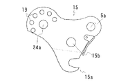
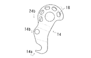
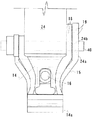
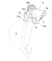
請求項1においては、旋回作業車のアーム(5)に枢支孔(5a)を介して枢支し、該アーム(5)の先端のアタッチメント(4)を脱着するアタッチメント脱着装置(11)において、該アタッチメント脱着装置(11)は、前記枢支孔(5a)を穿設した固定フック(15)と、該固定フック(15)に枢支ピン(40)により枢支する可動フック(14)と、該固定フック(15)と可動フック(14)の間に介装する油圧シリンダ(16)と油圧シリンダロッド(17)により構成し、該アタッチメント(4)に設けた2本の支持ピン(13a・13b)に、該固定フック(15)の支持ピン係止部(15a)と、該可動フック(14)に設けた支持ピン係止部(14a)を油圧シリンダ(16)により内側から開いて係合させる構成とし、該固定フック(15)と可動フック(14)が接当して摺動する部分のいずれかの面に、楔嵌合溝(71)を設け、該楔嵌合溝(71)に楔型ストッパー(70)を挿入して任意の固定フック(15)と可動フック(14)の間の距離において固定するものである。
請求項1の如く、旋回作業車のアーム(5)に枢支孔(5a)を介して枢支し、該アーム(5)の先端のアタッチメント(4)を脱着するアタッチメント脱着装置(11)において、該アタッチメント脱着装置(11)は、前記枢支孔(5a)を穿設した固定フック(15)と、該固定フック(15)に枢支ピン(40)により枢支する可動フック(14)と、該固定フック(15)と可動フック(14)の間に介装する油圧シリンダ(16)と油圧シリンダロッド(17)により構成し、該アタッチメント(4)に設けた2本の支持ピン(13a・13b)に、該固定フック(15)の支持ピン係止部(15a)と、該可動フック(14)に設けた支持ピン係止部(14a)を油圧シリンダ(16)により内側から開いて係合させる構成とし、該固定フック(15)と可動フック(14)が接当して摺動する部分のいずれかの面に、楔嵌合溝(71)を設け、該楔嵌合溝(71)に楔型ストッパー(70)を挿入して任意の固定フック(15)と可動フック(14)の間の距離において固定するので、油圧シリンダの故障などの不測の事態においても、可動フックが回動する事がなく、確実にアタッチメントの脱落を防止する事ができるのである。
また、可動フックのさまざまな位置に応じて、楔型ストッパー(70)を嵌合させる事ができるので、種々のアタッチメントの支持ピンに対応する事ができるのである。
さらに、少ない作業工数で楔型ストッパー(70)を挿嵌できるので、短い時間でのアタッチメントの交換作業が可能となるのである。
また、可動フックの様々な位置に応じて、楔型ストッパー(70)を嵌合させる事ができるので、種々のアタッチメントに対応する事ができるのである。
さらに、少ない作業工数で楔型ストッパー(70)を挿嵌できるので、短い時間でのアタッチメントの交換作業が可能となるのである。
4 アタッチメント
11 アタッチメント脱着装置
13a 支持ピン
13b 支持ピン
14 可動フック
15 固定フック
16 油圧シリンダ
18 挿嵌長孔
19 挿嵌孔
25 ピン挿通孔
26 係止凹部
28 ピン回動部
30 脱落防止ピン
31 ピン頭部
32 ピン胴体部
33 ピンリング
34 ピン係止プレート
35 ピン孔
36 枢支ピン係合孔
37 カバーリング
40 枢支ピン
50 スライド式脱落防止ピン
51 ピン回動プレート
52 脱落防止ピン
54 スライドピン
55 スプリング
56 スライドピン挿通孔
59 止め輪
60 回動爪体
62 スプライン軸
63 ボス
64 係合歯列
70 楔型ストッパー
71 楔嵌合溝
72 ワイヤー
Claims (3)
- 旋回作業車のアーム(5)に枢支孔(5a)を介して枢支し、該アーム(5)の先端のアタッチメント(4)を脱着するアタッチメント脱着装置(11)において、該アタッチメント脱着装置(11)は、前記枢支孔(5a)を穿設した固定フック(15)と、該固定フック(15)に枢支ピン(40)により枢支する可動フック(14)と、該固定フック(15)と可動フック(14)の間に介装する油圧シリンダ(16)と油圧シリンダロッド(17)により構成し、該アタッチメント(4)に設けた2本の支持ピン(13a・13b)に、該固定フック(15)の支持ピン係止部(15a)と、該可動フック(14)に設けた支持ピン係止部(14a)を油圧シリンダ(16)により内側から開いて係合させる構成とし、該固定フック(15)と可動フック(14)が接当して摺動する部分のいずれかの面に、楔嵌合溝(71)を設け、該楔嵌合溝(71)に楔型ストッパー(70)を挿入して任意の固定フック(15)と可動フック(14)の間の距離において固定することを特徴とする旋回作業車のアタッチメント脱落防止構造。
- 請求項1記載の旋回作業車のアタッチメント脱落防止構造において、前記可動フック(14)の外側に固定フック(15)を配置して摺動可能とし、該固定フック(15)の内側側面には、楔嵌合溝(71)を設け、該固定フック(15)の端部から内側に向けて、溝の深さが浅くなる勾配を構成し、前記アタッチメント(4)を係止した状態において、該楔型ストッパー(70)を楔嵌合溝(71)に挿嵌することで、前記油圧シリンダ(16)の故障などの不測の事態においても、該可動フック(14)が回動すると共に、該楔型ストッパー(70)が楔嵌合溝(71)に嵌合し、該可動フック(14)は、該楔型ストッパー(70)との接触面圧により回動を止めることを特徴とする旋回作業車のアタッチメント脱落防止構造。
- 請求項2記載の旋回作業車のアタッチメント脱落防止構造において、該楔型ストッパー(70)は平面視長方形型とし、側面視において上表面に勾配を設け、全体として楔形状とし、前記固定フック(15)又は可動フック(14)に一端を固定するワイヤー(72)を設け、該ワイヤー(72)の他端を、楔型ストッパー(70)の表面上に設けた継合孔を有する円筒状の継合部(73a)に継合したことを特徴とする旋回作業車のアタッチメント脱落防止構造。
Priority Applications (1)
| Application Number | Priority Date | Filing Date | Title |
|---|---|---|---|
| JP2008317617A JP4885936B2 (ja) | 2008-12-12 | 2008-12-12 | 旋回作業車のアタッチメント脱落防止構造 |
Applications Claiming Priority (1)
| Application Number | Priority Date | Filing Date | Title |
|---|---|---|---|
| JP2008317617A JP4885936B2 (ja) | 2008-12-12 | 2008-12-12 | 旋回作業車のアタッチメント脱落防止構造 |
Related Parent Applications (1)
| Application Number | Title | Priority Date | Filing Date |
|---|---|---|---|
| JP2000120104A Division JP4309018B2 (ja) | 2000-04-20 | 2000-04-20 | 旋回作業車のアタッチメント脱落防止構造 |
Publications (2)
| Publication Number | Publication Date |
|---|---|
| JP2009052402A true JP2009052402A (ja) | 2009-03-12 |
| JP4885936B2 JP4885936B2 (ja) | 2012-02-29 |
Family
ID=40503700
Family Applications (1)
| Application Number | Title | Priority Date | Filing Date |
|---|---|---|---|
| JP2008317617A Expired - Lifetime JP4885936B2 (ja) | 2008-12-12 | 2008-12-12 | 旋回作業車のアタッチメント脱落防止構造 |
Country Status (1)
| Country | Link |
|---|---|
| JP (1) | JP4885936B2 (ja) |
Cited By (3)
| Publication number | Priority date | Publication date | Assignee | Title |
|---|---|---|---|---|
| JP2011231505A (ja) * | 2010-04-27 | 2011-11-17 | Kana Yasuda | アタッチメント着脱装置 |
| KR101499129B1 (ko) * | 2013-11-27 | 2015-03-06 | 이해선 | 포크레인용 자동안전핀 |
| EP3434827A1 (en) * | 2017-07-25 | 2019-01-30 | Caterpillar Inc. | Coupler assembly for coupling an arm to a work tool |
Citations (3)
| Publication number | Priority date | Publication date | Assignee | Title |
|---|---|---|---|---|
| JPH01124854A (ja) * | 1987-11-09 | 1989-05-17 | Seiko Epson Corp | フォトマスク |
| JPH01124853A (ja) * | 1987-11-10 | 1989-05-17 | Konica Corp | ハロゲン化銀写真感光材料の処理方法及び水洗代替安定液 |
| JPH086833Y2 (ja) * | 1993-11-09 | 1996-02-28 | 敬植 山田 | 油圧ショベル用アダプタ |
-
2008
- 2008-12-12 JP JP2008317617A patent/JP4885936B2/ja not_active Expired - Lifetime
Patent Citations (3)
| Publication number | Priority date | Publication date | Assignee | Title |
|---|---|---|---|---|
| JPH01124854A (ja) * | 1987-11-09 | 1989-05-17 | Seiko Epson Corp | フォトマスク |
| JPH01124853A (ja) * | 1987-11-10 | 1989-05-17 | Konica Corp | ハロゲン化銀写真感光材料の処理方法及び水洗代替安定液 |
| JPH086833Y2 (ja) * | 1993-11-09 | 1996-02-28 | 敬植 山田 | 油圧ショベル用アダプタ |
Cited By (4)
| Publication number | Priority date | Publication date | Assignee | Title |
|---|---|---|---|---|
| JP2011231505A (ja) * | 2010-04-27 | 2011-11-17 | Kana Yasuda | アタッチメント着脱装置 |
| KR101499129B1 (ko) * | 2013-11-27 | 2015-03-06 | 이해선 | 포크레인용 자동안전핀 |
| EP3434827A1 (en) * | 2017-07-25 | 2019-01-30 | Caterpillar Inc. | Coupler assembly for coupling an arm to a work tool |
| US11274413B2 (en) | 2017-07-25 | 2022-03-15 | Caterpillar Inc. | Coupler assembly for coupling an arm to a work tool |
Also Published As
| Publication number | Publication date |
|---|---|
| JP4885936B2 (ja) | 2012-02-29 |
Similar Documents
| Publication | Publication Date | Title |
|---|---|---|
| US10184224B2 (en) | Quick coupler | |
| CA2590464A1 (en) | Quick coupling mechanism for tool attachment | |
| JP2010230113A (ja) | 2部材連結装置 | |
| JP4885936B2 (ja) | 旋回作業車のアタッチメント脱落防止構造 | |
| JP4912280B2 (ja) | アタッチメントカプラ | |
| JP4885935B2 (ja) | 旋回作業車のアタッチメント脱落防止構造 | |
| JP4309018B2 (ja) | 旋回作業車のアタッチメント脱落防止構造 | |
| JP4271819B2 (ja) | フック付きバケットリンク装置 | |
| JP5723761B2 (ja) | フック付き作業具リンク | |
| CN105899734B (zh) | 用于机械的器械的更换系统 | |
| KR101254193B1 (ko) | 중장비 작업기의 퀵체인지 구조 | |
| JP2014181532A (ja) | フック付きバケットリンク装置 | |
| JP2004084176A (ja) | ブレード装置 | |
| CN105934400A (zh) | 用于机器工具的定位系统 | |
| KR20150093360A (ko) | 건설기계용 퀵커플러 | |
| JP5347518B2 (ja) | 作業機械のブーム | |
| JP6394238B2 (ja) | ピン連結装置、ピン連結装置付きの建設機械及びピン連結装置用のピン保持具 | |
| JP2006274589A (ja) | 建設機械のエンドアタッチメント装着装置 | |
| KR20130039043A (ko) | 이중안전장치를 갖춘 어태치먼트용 클램프 | |
| JP4002664B2 (ja) | 重量物吊上げ用フック装置 | |
| KR101330620B1 (ko) | 안전결합구조를 포함하는 어태치먼트 교환장치 | |
| JP4609431B2 (ja) | 連結ピンの脱着装置 | |
| JP5094785B2 (ja) | ハンドホール用点検蓋旋錠装置 | |
| KR101380542B1 (ko) | 안전 고정핀을 포함하는 어태치먼트 교환장치 | |
| JP2019138002A (ja) | フック付バケットリンク装置及びそれを備えた建設機械 |
Legal Events
| Date | Code | Title | Description |
|---|---|---|---|
| A621 | Written request for application examination |
Free format text: JAPANESE INTERMEDIATE CODE: A621 Effective date: 20081212 |
|
| A977 | Report on retrieval |
Free format text: JAPANESE INTERMEDIATE CODE: A971007 Effective date: 20110511 |
|
| A131 | Notification of reasons for refusal |
Free format text: JAPANESE INTERMEDIATE CODE: A131 Effective date: 20110517 |
|
| A521 | Written amendment |
Free format text: JAPANESE INTERMEDIATE CODE: A523 Effective date: 20110610 |
|
| TRDD | Decision of grant or rejection written | ||
| A01 | Written decision to grant a patent or to grant a registration (utility model) |
Free format text: JAPANESE INTERMEDIATE CODE: A01 Effective date: 20111206 |
|
| A01 | Written decision to grant a patent or to grant a registration (utility model) |
Free format text: JAPANESE INTERMEDIATE CODE: A01 |
|
| A61 | First payment of annual fees (during grant procedure) |
Free format text: JAPANESE INTERMEDIATE CODE: A61 Effective date: 20111208 |
|
| FPAY | Renewal fee payment (event date is renewal date of database) |
Free format text: PAYMENT UNTIL: 20141216 Year of fee payment: 3 |
|
| R150 | Certificate of patent or registration of utility model |
Ref document number: 4885936 Country of ref document: JP Free format text: JAPANESE INTERMEDIATE CODE: R150 Free format text: JAPANESE INTERMEDIATE CODE: R150 |
|
| EXPY | Cancellation because of completion of term |