JP2009062017A - Tonneau cover device for vehicle - Google Patents

Tonneau cover device for vehicle Download PDF

Info

Publication number
JP2009062017A
JP2009062017A JP2007233971A JP2007233971A JP2009062017A JP 2009062017 A JP2009062017 A JP 2009062017A JP 2007233971 A JP2007233971 A JP 2007233971A JP 2007233971 A JP2007233971 A JP 2007233971A JP 2009062017 A JP2009062017 A JP 2009062017A
Authority
JP
Japan
Prior art keywords
tonneau cover
vehicle
sheet
tonneau
slider
Prior art date
Legal status (The legal status is an assumption and is not a legal conclusion. Google has not performed a legal analysis and makes no representation as to the accuracy of the status listed.)
Granted
Application number
JP2007233971A
Other languages
Japanese (ja)
Other versions
JP5281260B2 (en
Inventor
Tomoatsu Tani
知篤 谷
Isao Hirayama
勲 平山
Kensho Haba
憲昭 羽場
Current Assignee (The listed assignees may be inaccurate. Google has not performed a legal analysis and makes no representation or warranty as to the accuracy of the list.)
Ashimori Industry Co Ltd
Mazda Motor Corp
Original Assignee
Ashimori Industry Co Ltd
Mazda Motor Corp
Priority date (The priority date is an assumption and is not a legal conclusion. Google has not performed a legal analysis and makes no representation as to the accuracy of the date listed.)
Filing date
Publication date
Application filed by Ashimori Industry Co Ltd, Mazda Motor Corp filed Critical Ashimori Industry Co Ltd
Priority to JP2007233971A priority Critical patent/JP5281260B2/en
Publication of JP2009062017A publication Critical patent/JP2009062017A/en
Application granted granted Critical
Publication of JP5281260B2 publication Critical patent/JP5281260B2/en
Active legal-status Critical Current
Anticipated expiration legal-status Critical

Links

Images
Landscapes

  • Vehicle Step Arrangements And Article Storage (AREA)

Abstract

【課題】 折り重なった状態で巻き込まれるおそれのあるトノカバーシートの垂れ下がりを有効に防止する車両用トノカバー装置を提供する。
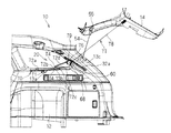
【解決手段】 車両10の荷室12を覆って引き出し側端部がハッチバックドア14に連結されると共にハッチバックドア14の開放状態でリアピラーガーニッシュ13cと対向する両側部分に切欠部78cが形成されたシート部材78と、荷室12に取り付けられると共にシート部材78が連結されてシート部材78を巻き取る方向に付勢するシート巻取部79とを備える。切欠部78cにより形成された幅狭位置よりシート部材78の引き出し方向に向けて幅広となる広がり領域部Sに棒状芯材91を設ける。
【選択図】 図25
PROBLEM TO BE SOLVED: To provide a tonneau cover device for a vehicle that effectively prevents drooping of a tonneau cover sheet that may be caught in a folded state.
SOLUTION: A seat in which a drawer side end portion is connected to a hatchback door 14 covering a cargo compartment 12 of a vehicle 10 and a notch 78c is formed on both side portions facing a rear pillar garnish 13c when the hatchback door 14 is opened. A member 78 and a sheet take-up portion 79 that is attached to the luggage compartment 12 and is urged in a direction in which the sheet member 78 is connected to wind up the sheet member 78 are provided. A rod-shaped core member 91 is provided in the widened area S that becomes wider from the narrow position formed by the notch 78c toward the drawing direction of the sheet member 78.
[Selection] FIG.

Description

本発明は、車両のハッチバックドアの開閉操作に連動して荷室上方を覆い或いは開放させることができる車両用トノカバー装置に関する。   The present invention relates to a tonneau cover device for a vehicle that can cover or open an upper part of a cargo compartment in conjunction with an opening / closing operation of a hatchback door of the vehicle.

近年、ハッチバックタイプの車両に設けられるトノカバー装置においては、トノカバーシートの一端がハッチバックドアに取り付けられ、他端がリアシートの後方近傍に配置される巻取機構を備えたシート巻取部に巻き取られる構造となっている。そして、ハッチバックドアの開放・閉鎖操作によって、必要長さのトノカバーシートがシート巻取部から引き出し・巻き取り可能とされている。   In recent years, in a tonneau cover device provided in a hatchback type vehicle, one end of a tonneau cover seat is attached to a hatchback door, and the other end is wound around a seat winder provided with a winding mechanism disposed near the rear of the rear seat. It has a structure. A tonneau cover sheet having a required length can be pulled out and taken up from the sheet take-up portion by opening and closing the hatch back door.

通常この種の車両においては、互いに対向するリアピラーガーニッシュの間隔は、車両の下方から上方に向かって荷室幅より漸次狭くなっているため、ハッチバックドアの開放時に、リアピラーガーニッシュとトノカバーシートとの相互干渉を有効に回避すべく、リアピラーガーニッシュと対向するトノカバーシートの両側部分に、干渉回避用の切欠部を形成する。   Usually, in this type of vehicle, the distance between the rear pillar garnishes facing each other is gradually narrower than the width of the cargo compartment from the bottom to the top of the vehicle. Therefore, when the hatchback door is opened, the rear pillar garnish and the tonneau cover seat In order to effectively avoid interference, notch portions for avoiding interference are formed on both side portions of the tonneau cover sheet facing the rear pillar garnish.

しかしながら、トノカバーシートの両側部分に切欠部を形成すると、切欠部が形成された位置で最も幅狭な部分が生じ、その幅狭位置よりトノカバーシートの引き出し方向に向けて幅広となる形状となる。そのため、このトノカバーシートの引き出し方向に向けて幅広となる広がり領域部において、その両側縁部に垂れ下がりが生じるおそれがある。   However, when the notch portions are formed on both side portions of the tonneau cover sheet, the narrowest portion is formed at the position where the notch portion is formed, and the shape becomes wider from the narrow position toward the drawing direction of the tonneau cover sheet. For this reason, there is a risk that the both side edges of the expanded region that becomes wider in the pulling-out direction of the tonneau cover sheet may sag.

このような広がり領域部は、シート巻取部側の幅が狭く、引き出し方向に向けて幅が広がっているため、前記のような垂れ下がりが生じた状態では、両側の垂れ下がり部分における車幅方向の幅の狭い方がシート巻取部側に近く、車幅方向の幅の広い方がシート巻取部から遠くに位置される。そのため、このような垂れ下がりが生じた状態で、シート巻取部にトノカバーシートが巻き取られていくと、垂れ下がり部分を折り重なった状態で巻き込んでしまうおそれがあり、巻取動作が円滑になされないおそれがある。   Since such a spread area portion has a narrow width on the sheet winding portion side and widens in the pull-out direction, in the state where the above-described sag occurs, the vehicle width direction in the sag portions on both sides The narrower one is closer to the seat winder side, and the wider one in the vehicle width direction is located farther from the seat winder. Therefore, when the tonneau cover sheet is wound around the sheet winding portion in a state where such a sag occurs, there is a possibility that the sag portion may be wound in a folded state, and the winding operation may not be performed smoothly. There is.

また、トノカバーシートを折り重なった状態で巻き込んだ場合には、トノカバーシートに折り癖が生じて、見栄えが悪くなると共に、耐久性にも問題が生じるおそれがある。   In addition, when the tonneau cover sheet is wound in a folded state, the tonneau cover sheet may be folded, resulting in a poor appearance and a problem in durability.

特に、カーテンバッグを備える車両においては、バッグを展開させるためのインフレータをリアピラーガーニッシュ内に備えるため、近年、リアピラーガーニッシュが大きくなり、前記切欠部も車幅方向および車両前後方向に大きく形成されるので、トノカバーシートの前記垂れ下がりもより大きくなり、巻取動作ができなくなるおそれもあった。   In particular, in a vehicle equipped with a curtain bag, an inflator for deploying the bag is provided in the rear pillar garnish. Therefore, in recent years, the rear pillar garnish is large, and the notch is also formed large in the vehicle width direction and the vehicle front-rear direction. Further, the sagging of the tonneau cover sheet becomes larger, and there is a possibility that the winding operation cannot be performed.

そこで、本発明は上記問題点に鑑み、折り重なった状態で巻き込まれるおそれのあるトノカバーシートの垂れ下がりを有効に防止する車両用トノカバー装置を提供することを目的とする。   In view of the above problems, an object of the present invention is to provide a tonneau cover device for a vehicle that effectively prevents drooping of a tonneau cover sheet that may be caught in a folded state.

前記課題を解決するための技術的手段は、対向するリアピラーガーニッシュの間隔が、車両の下方から上方に向かって荷室幅より漸次狭く形成されているハッチバックタイプの車両に設けられ、ハッチバックドアの操作に連動して引き出しおよび巻き取り可能とされた車両用トノカバー装置において、車両の荷室を覆って引き出し側端部が前記ハッチバックドアに連結されると共にハッチバックドア開放状態で前記リアピラーガーニッシュと対向する両側部分に切欠部が形成されたトノカバーシートと、荷室に取り付けられると共にトノカバーシートの基部が連結されてトノカバーシートを巻き取る方向に付勢するシート巻取部とを備え、前記切欠部により形成された幅狭位置よりトノカバーシートの引き出し方向に向けて幅広となる広がり領域部に垂れ下がり防止手段を設けた点にある。   The technical means for solving the above problem is provided in a hatchback type vehicle in which the interval between the opposed rear pillar garnishes is formed to be gradually narrower than the cargo compartment width from the lower side to the upper side of the vehicle. In the tonneau cover device for a vehicle that can be pulled out and wound in conjunction with the door, both sides facing the rear pillar garnish in a state in which the drawer side end portion is connected to the hatch back door and the hatch back door is open, covering the cargo compartment of the vehicle A tonneau cover sheet having a notch formed in the part, and a sheet take-up part that is attached to the luggage compartment and that is connected to the base of the tonneau cover sheet and biases the tonneau cover sheet in the direction of winding the tonneau cover sheet. Widen from the narrow position toward the tonneau cover sheet pull-out direction It lies in providing a means for preventing sag frequency band.

また、前記トノカバーシートは、前記ハッチバックドアの閉鎖状態で前記シート巻取部から引き出されている第1カバー部と、該第1カバー部に縫製されて連続し、ハッチバックドアの開放操作により引き出されると共に前記切欠部が形成されている第2カバー部とからなり、前記第1カバー部と前記第2カバー部とを縫製する部分に前記垂れ下がり防止手段を設けた構造としてもよい。   The tonneau cover sheet is continuous with the first cover part pulled out from the sheet take-up part in the closed state of the hatch back door, and is sewn on the first cover part, and is pulled out by the opening operation of the hatch back door. And a second cover portion in which the cutout portion is formed, and the sag prevention means may be provided in a portion where the first cover portion and the second cover portion are sewn.

さらに、前記シート巻取部が、ハッチバックドアの開放操作に連動して車両上方向に移動されると共に、ハッチバックドアの閉鎖操作に連動して車両下方向に移動される構造としてもよい。   Further, the seat winding unit may be moved in the upward direction of the vehicle in conjunction with the opening operation of the hatch back door and may be moved in the downward direction of the vehicle in conjunction with the closing operation of the hatch back door.

また、前記垂れ下がり防止手段は、前記トノカバーシートの幅方向に沿って装着された棒状芯材からなり、前記棒状芯材は前記トノカバーシートの引き出し方向に離隔して複数位置に配置されると共に、前記シート巻取部の巻芯に対してトノカバーシートが巻き取られた際に、各棒状芯材が互いに重ならない位置に配置されている構造としてもよい。   The sagging prevention means comprises a rod-shaped core member mounted along the width direction of the tonneau cover sheet, and the rod-shaped core member is disposed at a plurality of positions apart from each other in the pulling-out direction of the tonneau cover sheet. When the tonneau cover sheet is wound around the core of the sheet winding unit, the rod-shaped core members may be arranged at positions that do not overlap each other.

本発明の車両用トノカバー装置によれば、車両の荷室を覆って引き出し側端部がハッチバックドアに連結されると共にハッチバックドア開放状態でリアピラーガーニッシュと対向する両側部分に切欠部が形成されたトノカバーシートと、荷室に取り付けられると共にトノカバーシートの基部が連結されてトノカバーシートを巻き取る方向に付勢するシート巻取部とを備え、切欠部により形成された幅狭位置よりトノカバーシートの引き出し方向に向けて幅広となる広がり領域部に垂れ下がり防止手段を設けた構造とされており、垂れ下がり防止手段によって、引き出し方向に幅広となる広がり領域部の垂れ下がりが有効に防止できるため、シート巻取部でトノカバーシートが巻き取られる際に、折り重なった状態での巻き込みがなく、巻取動作が円滑になされる。従って、切欠部の形状や大きさにかかわらず対応でき、トノカバーシートに折り癖が生じず、見栄えの向上が図れ、耐久性に優れる利点がある。   According to the tonneau cover device for a vehicle of the present invention, the tonneau cover that covers the cargo compartment of the vehicle and that has the drawer side end connected to the hatchback door and that has notches formed on both side portions facing the rear pillar garnish when the hatchback door is open. A sheet take-up portion that is attached to the luggage compartment and is connected to a base portion of the tonneau cover sheet and urges the tonneau cover sheet in a direction to take up the tonneau cover sheet, and the tonneau cover sheet is pulled out from a narrow position formed by the notch Since the sag prevention means is provided in the widened area part that becomes wider toward the front, and the sag prevention means can effectively prevent the sag of the widened area part that becomes wide in the pull-out direction. When the tonneau cover sheet is rolled up, there is no winding in the folded state and the winding operation It is carried out smoothly. Therefore, it can be handled regardless of the shape and size of the notch, there is no crease in the tonneau cover sheet, the appearance can be improved, and the durability is excellent.

また、トノカバーシートは、ハッチバックドアの閉鎖状態でシート巻取部から引き出されている第1カバー部と、該第1カバー部に縫製されて連続し、ハッチバックドアの開放操作により引き出されると共に切欠部が形成されている第2カバー部とからなり、第1カバー部と第2カバー部とを縫製する部分に垂れ下がり防止手段を設けた構造とすれば、第1カバー部と第2カバー部との縫製と同時に垂れ下がり防止手段を取り付けることができ、組み付け作業が容易で、その作業時間も短縮できる利点がある。   The tonneau cover sheet is continuous with the first cover part pulled out from the sheet take-up part in the closed state of the hatch back door, and is sewn on the first cover part, and is pulled out by the opening operation of the hatch back door and the notch part. If the first cover part and the second cover part are provided with a structure for preventing the sagging at the part where the first cover part and the second cover part are sewn, the first cover part and the second cover part are formed. At the same time as sewing, the dripping prevention means can be attached, so that the assembling work is easy and the working time can be shortened.

さらに、シート巻取部が、ハッチバックドアの開放操作に連動して車両上方向に移動されると共に、ハッチバックドアの閉鎖操作に連動して車両下方向に移動される構造とすれば、ハッチバックドアの開放状態で、シート巻取部が上方に移動した位置にあるため、利用者にとって荷室内が確認しやすく、荷物の積み卸し作業がより容易になるという利点がある。   Furthermore, if the seat winder is configured to move upward in the vehicle in conjunction with the opening operation of the hatchback door and in the downward direction in conjunction with the closing operation of the hatchback door, Since the seat winder is located in the open position in the opened state, there is an advantage that it is easy for the user to check the cargo compartment and the work of loading and unloading the cargo becomes easier.

また、垂れ下がり防止手段は、トノカバーシートの幅方向に沿って装着された棒状芯材からなり、棒状芯材はトノカバーシートの引き出し方向に離隔して複数位置に配置されると共に、シート巻取部の巻芯に対してトノカバーシートが巻き取られた際に、各棒状芯材が互いに重ならない位置に配置されている構造とすれば、広がり領域部における垂れ下がりがより確実に防止できると共に、シート巻取部にトノカバーシートが巻き取られた際の巻き径が大きくなるのを有効に防止でき、コンパクト化が図れる。   The sagging prevention means is composed of a rod-shaped core member mounted along the width direction of the tonneau cover sheet, and the rod-shaped core members are arranged at a plurality of positions apart from each other in the pulling direction of the tonneau cover sheet. When the tonneau cover sheet is wound around the winding core, the rod-shaped core members are arranged at positions where they do not overlap with each other. It is possible to effectively prevent the winding diameter when the tonneau cover sheet is wound around the portion from being increased, and to achieve compactness.

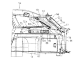
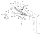
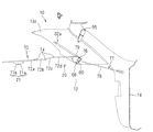
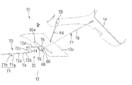
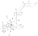
以下、第1の実施形態に係る車両用トノカバー装置20について説明する。図1はハッチバックタイプの車両10に設けられたトノカバー装置20を示す斜視説明図であり、図2は同トノカバー装置20を示す側面説明図であり、図3は同トノカバー装置20の内部構成を示す側面説明図である。また、図4〜図6はハッチバックドア14を閉じた状態から開いた状態にする際の変化を示す説明図であり、図4はハッチバックドア14を完全に閉じた閉鎖状態、図5はハッチバックドア14を途中まで開いた状態、図6がハッチバックドア14を完全に開いた開放状態をそれぞれ示している。   Hereinafter, the tonneau cover apparatus 20 for vehicles which concerns on 1st Embodiment is demonstrated. 1 is a perspective explanatory view showing a tonneau cover device 20 provided in a hatchback type vehicle 10, FIG. 2 is an explanatory side view of the tonneau cover device 20, and FIG. 3 shows an internal configuration of the tonneau cover device 20. FIG. 4 to 6 are explanatory views showing changes when the hatchback door 14 is changed from a closed state to an open state, FIG. 4 is a closed state in which the hatchback door 14 is completely closed, and FIG. 5 is a hatchback door. FIG. 6 shows an open state in which the hatchback door 14 is completely opened.

このトノカバー装置20は、ハッチバックドア14で開閉される荷室12を有する車両10に設けられる。即ち、車両10の後方に、乗員室と連なる荷室12が設けられており、この荷室12の後方開口は、ハッチバックドア14により開閉可能とされる。本トノカバー装置20は、このような車両10の荷室12に組み込まれる。   The tonneau cover device 20 is provided in a vehicle 10 having a luggage compartment 12 that is opened and closed by a hatchback door 14. That is, a cargo compartment 12 connected to the passenger compartment is provided behind the vehicle 10, and the rear opening of the cargo compartment 12 can be opened and closed by the hatchback door 14. The tonneau cover device 20 is incorporated in such a luggage compartment 12 of the vehicle 10.

トノカバー装置20は、一対のレール部30と(図3参照)、一対のスライダ部60と、前部のトノボード部70と、後部のトノカバー部77と、スライダ駆動機構部40(図3参照)とを備えている。   The tonneau cover device 20 includes a pair of rail sections 30 (see FIG. 3), a pair of slider sections 60, a front tonneau board section 70, a rear tonneau cover section 77, and a slider drive mechanism section 40 (see FIG. 3). It has.

このトノカバー装置20の基本的構成および基本的動作について説明すると、一対のレール部30は、車両10後部両側の互いに対向するいわゆるリアピラーガーニッシュ13c内に組み込まれている。また、トノボード部70は、折畳み可能に構成されており、その前部が荷室12前方部分に支持されると共に、その後部がトノカバー部77におけるシート巻取部79に連結され、このシート巻取部79が一対のスライダ部60にそれぞれ取り付けられている。そして、シート巻取部79より引き出しおよび巻き取り可能とされたシート部材78の引き出し側端部がハッチバックドア14に着脱自在に連結されている。また、スライダ駆動機構部40は、レール部30に組み込まれ、ハッチバックドア14の開閉操作に連動して一対のスライダ部60を移動させるように構成されている。   The basic configuration and basic operation of the tonneau cover device 20 will be described. The pair of rail portions 30 are incorporated in so-called rear pillar garnishes 13c facing each other on both sides of the rear portion of the vehicle 10. Further, the tonneau board portion 70 is configured to be foldable, and a front portion thereof is supported by the front portion of the cargo compartment 12 and a rear portion thereof is connected to a sheet winding portion 79 in the tonneau cover portion 77, The portions 79 are attached to the pair of slider portions 60, respectively. The end portion on the drawer side of the sheet member 78 that can be pulled out and wound from the sheet winding portion 79 is detachably connected to the hatch back door 14. The slider drive mechanism 40 is incorporated in the rail portion 30 and is configured to move the pair of slider portions 60 in conjunction with the opening / closing operation of the hatch back door 14.

そして、ハッチバックドア14の閉鎖状態では、一対のスライダ部60が一対のレール部30の後端部に位置しており、トノボード部70およびトノカバー部77が展開して荷室12の上方を覆った状態となっている(図1〜図4参照)。この状態で、ハッチバックドア14が開放操作により開動作されると、スライダ駆動機構部40が駆動されて、一対のスライダ部60が一対のレール部30の前方に向けて移動する(図5参照)。そして、ハッチバックドア14が完全に開いた開放状態になると、一対のスライダ部60が一対のレール部30の前端部に位置し、トノボード部70が折畳まれるようにして荷室12の上方を開放させた状態になる(図6参照)。一方、トノカバー部77のシート部材78はハッチバックドア14の開放操作に伴って、シート巻取部79内から適宜引き出された状態となる。また、この状態からハッチバックドア14を閉鎖操作して閉じると、一対のスライダ部60が一対のレール部30の後方に移動し、ハッチバックドア14を完全に閉じると上記のようにトノボード部70およびトノカバー部77が荷室の上方を覆った初期状態に復帰する。   In the closed state of the hatch back door 14, the pair of slider portions 60 are located at the rear end portions of the pair of rail portions 30, and the tonneau board portion 70 and the tonneau cover portion 77 are deployed to cover the upper side of the cargo compartment 12. It is in a state (see FIGS. 1 to 4). In this state, when the hatch back door 14 is opened by an opening operation, the slider drive mechanism 40 is driven, and the pair of slider parts 60 moves toward the front of the pair of rail parts 30 (see FIG. 5). . When the hatch back door 14 is fully opened, the pair of slider portions 60 are positioned at the front end portions of the pair of rail portions 30 so that the tonneau board portion 70 is folded over the cargo compartment 12. It will be in the open state (refer FIG. 6). On the other hand, the sheet member 78 of the tonneau cover portion 77 is appropriately pulled out from the seat winding portion 79 with the opening operation of the hatch back door 14. Further, when the hatchback door 14 is closed and closed from this state, the pair of slider portions 60 moves to the rear of the pair of rail portions 30, and when the hatchback door 14 is completely closed, the tonneau board portion 70 and the tonneau cover as described above. The part 77 returns to the initial state covering the upper side of the cargo compartment.

以下、各部構成についてより具体的に説明する。   Hereinafter, each part structure is demonstrated more concretely.

<トノボード部、トノカバー部>
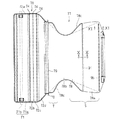
まず、トノボード部70およびトノカバー部77について説明する。図7はトノボード部70およびトノカバー部77を示す平面図であり、図8はトノボード部70およびトノカバー部77を示す側面図であり、図9はトノボード部70の要部を示す断面図であり、図10はシート部材78における図7のX−X線断面図、図11はシート部材78における図7のXI−XI線断面図である。
<Tonneau board and tonneau cover>
First, the tonneau board part 70 and the tonneau cover part 77 will be described. 7 is a plan view showing the tonneau board part 70 and the tonneau cover part 77, FIG. 8 is a side view showing the tonneau board part 70 and the tonneau cover part 77, and FIG. 9 is a sectional view showing the main part of the tonneau board part 70. 10 is a cross-sectional view of the sheet member 78 taken along the line XX of FIG. 7, and FIG. 11 is a cross-sectional view of the sheet member 78 taken along the line XI-XI of FIG.

図1〜図9に示すように、トノボード部70は、複数の板状部72a、72b、72c、72dと、少なくとも1つの屈曲部74とを有したいわゆるトノボード構造とされている。   As shown in FIGS. 1 to 9, the tonneau board portion 70 has a so-called tonneau board structure having a plurality of plate-like portions 72 a, 72 b, 72 c, 72 d and at least one bent portion 74.

複数の板状部72a、72b、72c、72dは、荷室12の上方を覆うことが可能な平板状部分を、車両10前後方向において複数に分割したような板状部材に形成されている。つまり、各板状部72a、72b、72c、72dは、その幅寸法が荷室12の幅寸法と略同じ或いはそれよりも短く、かつ、それぞれの車両10前後方向における寸法は荷室12の車両10前後方向の長さ寸法よりも短い横長の板状部材に形成されている。このような板状部72a、72b、72c、72dは、樹脂板や木板、金属板等で構成される。ここでは、荷室12の上方を覆うことが可能な平板状部分を4つに分割している。より具体的には、当該平板状部分を、車両10前後方向において2分割し、その後方部分をさらに2分割し、当該後方部分における前方部分をさらに2分割することで、合計4つに分割し、その前側から後方に向けた各部分を、それぞれ板状部72a、72b、72c、72dとしている。なお、最も後方の板状部72dは、荷室12の形状にあわせて、後方に向けて順次幅狭になる板形状に形成されている。   The plurality of plate-like portions 72 a, 72 b, 72 c, 72 d are formed as plate-like members obtained by dividing a flat plate-like portion capable of covering the upper part of the cargo compartment 12 into a plurality of portions in the vehicle 10 front-rear direction. That is, each plate-like portion 72a, 72b, 72c, 72d has a width dimension that is substantially the same as or shorter than the width dimension of the cargo compartment 12, and the dimension in the longitudinal direction of each vehicle 10 is the vehicle in the cargo compartment 12. It is formed in the horizontally long plate-shaped member shorter than the length dimension of 10 front-back direction. Such plate-like parts 72a, 72b, 72c, 72d are constituted by a resin plate, a wooden plate, a metal plate, or the like. Here, the flat part which can cover the upper part of the luggage compartment 12 is divided into four. More specifically, the flat plate portion is divided into two parts in the vehicle 10 longitudinal direction, the rear part thereof is further divided into two parts, and the front part of the rear part is further divided into two parts, for a total of four parts. The portions directed from the front side to the rear are plate-like portions 72a, 72b, 72c, 72d, respectively. The rearmost plate-like portion 72d is formed in a plate shape that gradually narrows toward the rear in accordance with the shape of the luggage compartment 12.

なお、上記の分割態様は一例であり、当該例に限られない。各板状部72a、72b、72c、72dの車両前後方向における長さは上記例に限らず任意であるし、また、分割状とする数も、2つ又は3つに分割され、或いは、5つ以上に分割された構成であってもよい。   In addition, said division | segmentation aspect is an example and is not restricted to the said example. The length of each plate-like portion 72a, 72b, 72c, 72d in the vehicle front-rear direction is not limited to the above example, and the number of divisions is also divided into two or three, or 5 The structure divided | segmented into two or more may be sufficient.

また、屈曲部74は、上記各板状部72a、72b、72c、72d同士を屈曲可能に連結するように構成されている。ここでは、屈曲部74は、板状部72a、72b間と、板状部72b、72c間と、板状部72c、72d間とに合計3つ設けられている。   Moreover, the bending part 74 is comprised so that each said plate-shaped part 72a, 72b, 72c, 72d may be connected so that bending is possible. Here, a total of three bent portions 74 are provided between the plate-like portions 72a and 72b, between the plate-like portions 72b and 72c, and between the plate-like portions 72c and 72d.

屈曲部74は、次の構成により、各板状部72a、72b、72c、72d同士を屈曲可能に連結している。即ち、板状部72a、72b、72c、72dの一方表面および他方表面のそれぞれに対して、各板状部72a、72b、72c、72d同士を連結するように連続して、布部材73が密着状に配設される。また、布部材73が配設された状態で、各板状部72a、72b、72c、72d間には隙間が設けられており、当該隙間に樹脂や金属等で形成された細長板状部材74aが配設される。そして、当該細長板状部材74aと板状部72a、72b、72c、72dとの間で、一対の布部材73同士が縫合等されて、幅方向線状に相互接合される。これにより、各板状部72a、72b、72c、72d間に、各板状部72a、72b、72c、72d間の布部材73部分および細長板状部材74aと線状接合部分73aとで構成される屈曲部74が構成される(図9参照)。このような屈曲部74は、細長板状部材74aを挟んだ2箇所で屈曲できるため、各板状部72a、72b、72c、72dの厚みによる影響を抑制して、180゜に近い角度に屈曲させることができるという利点がある。もっとも、屈曲部74自体は、板状部72a、72b、72c、72dを屈曲できる構成であればよく、その他種々のヒンジ構造等を含む屈曲可能な構成を採用することができる。   The bent portion 74 connects the plate-like portions 72a, 72b, 72c, and 72d so as to be bendable by the following configuration. That is, the cloth member 73 is in close contact with each of the plate-like portions 72a, 72b, 72c, and 72d so as to connect the plate-like portions 72a, 72b, 72c, and 72d to each other. Arranged in a shape. In addition, with the cloth member 73 disposed, gaps are provided between the plate-like portions 72a, 72b, 72c, 72d, and the elongated plate-like member 74a formed of resin, metal, or the like in the gap. Is disposed. And between the said elongate plate-shaped member 74a and plate-shaped part 72a, 72b, 72c, 72d, a pair of cloth member 73 is stitched | sutured etc., and is mutually joined by the width direction linear form. Thereby, it is comprised between each plate-shaped part 72a, 72b, 72c, 72d by the cloth member 73 part between each plate-shaped part 72a, 72b, 72c, 72d and the elongate plate-shaped member 74a, and the linear joining part 73a. A bent portion 74 is formed (see FIG. 9). Since such a bent portion 74 can be bent at two positions sandwiching the elongated plate-like member 74a, the influence of the thickness of each plate-like portion 72a, 72b, 72c, 72d is suppressed and bent at an angle close to 180 °. There is an advantage that can be made. But the bending part 74 itself should just be the structure which can bend the plate-shaped parts 72a, 72b, 72c, 72d, and the structure which can be bent including other various hinge structures etc. is employable.

また、トノボード部70の前端部、即ち、もっとも前方の板状部72aにトノカバー支持軸部71が設けられている。より具体的には、板状部72aの下側面であって車両前後方向における前半部の両側部に一対の軸支部71aが設けられると共に、当該一対の軸支部71aに棒状の軸部71bが支持されている。この軸部71bの両端部は、板状部72aの両側より突出しており、荷室12の両側壁部13に設けられた軸受部13aに回転可能に軸支されるようになっている(図2参照)。そして、軸部71bの両端部を軸受部13aで支持することによって、トノボード部70の前端部が荷室12の車両10前方部分で回転可能に支持されている。   Further, a tonneau cover support shaft portion 71 is provided at the front end portion of the tonneau board portion 70, that is, the frontmost plate-like portion 72a. More specifically, a pair of shaft support portions 71a are provided on both sides of the front half in the vehicle front-rear direction on the lower surface of the plate-like portion 72a, and a rod-shaped shaft portion 71b is supported by the pair of shaft support portions 71a. Has been. Both end portions of the shaft portion 71b protrude from both sides of the plate-like portion 72a, and are rotatably supported by bearing portions 13a provided on both side wall portions 13 of the cargo compartment 12 (see FIG. 2). And the front-end part of the tonneau board part 70 is rotatably supported by the vehicle 10 front part of the luggage compartment 12 by supporting the both ends of the axial part 71b with the bearing part 13a.

また、荷室12の両側壁部13であって軸受部13aよりも後方部分には、トノボード部70の両側部を受けるトノボード受部13bが設けられている(図2参照)。そして、トノボード部70のうちトノカバー支持軸部71よりも後方部分の両側部が、トノボード受部13bに載置状に支持されるようになっている。そして、トノボード部70は、軸部71b回りに、その後方部分を上方に持上げるようにして回転可能とされている。   Moreover, the tonneau board receiving part 13b which receives the both sides of the tonneau board part 70 is provided in the both-side wall part 13 of the luggage compartment 12, and the back part rather than the bearing part 13a (refer FIG. 2). And the both sides of a rear part rather than the tonneau cover support shaft part 71 among the tonneau board parts 70 are supported by the tonneau board receiving part 13b in a mounting form. The tonneau board portion 70 is rotatable around the shaft portion 71b so as to lift the rear portion upward.

また、トノボード部70の後端部は、トノカバー部77のシート巻取部79に連結されており、このシート巻取部79の両側部に、外方向に突出する連結支持部76が設けられている。そして、この連結支持部76が、スライダ部60に連結されて取り付けられた構造とされている。   Further, the rear end portion of the tonneau board portion 70 is connected to the sheet winding portion 79 of the tonneau cover portion 77, and connection support portions 76 that project outward are provided on both sides of the sheet winding portion 79. Yes. The connection support portion 76 is connected to the slider portion 60 and attached thereto.

このトノカバー部77は、トノカバーシートを構成するシート部材78と、当該シート部材78の基部が連結されて巻取方向に常時付勢すると共に、引き出しおよび巻き取り可能な巻取構造を有するシート巻取部79とを備えた巻取式構造とされている。そして、シート部材78における引き出し側端部は、ハッチバックドア14に着脱可能に取り付けられている。   The tonneau cover portion 77 is a sheet winding member having a winding structure in which a sheet member 78 constituting a tonneau cover sheet and a base portion of the sheet member 78 are coupled to constantly urge the sheet member 78 in the winding direction and can be pulled out and wound up. A winding structure including a portion 79 is provided. And the drawer side edge part in the sheet | seat member 78 is attached to the hatch back door 14 so that attachment or detachment is possible.

また、シート部材78は、ハッチバックドア14の閉鎖状態で、シート巻取部79から所定長さ引き出されてトノボード部70の後端部とハッチバックドア14との間の荷室12を覆う第1カバー部78aと、この第1カバー部78aに縫製により連続状に接続され、ハッチバックドア14の開放操作によりシート巻取部79から引き出される第2カバー部78bとから構成されている(図1、図9、図21、図23、図25参照)。例えば、外部に露出状態となる第1カバー部78aは布状生地からなり、ハッチバックドア14の開閉操作に連動して引き出し・巻き取り可能とされる第2カバー部78bはメッシュ状生地から構成されている。なお、第1カバー部78aと同じ生地よりなる1枚ものであってもよい。   Further, the seat member 78 is a first cover that covers the cargo compartment 12 between the rear end portion of the tonneau board portion 70 and the hatch back door 14 by being pulled out from the seat winding portion 79 by a predetermined length when the hatch back door 14 is closed. Part 78a and a second cover part 78b that is continuously connected to the first cover part 78a by sewing and is pulled out from the sheet take-up part 79 by the opening operation of the hatch back door 14 (FIG. 1, FIG. 9, FIG. 21, FIG. 23, FIG. 25). For example, the first cover part 78a exposed to the outside is made of cloth-like cloth, and the second cover part 78b that can be pulled out and wound in conjunction with the opening / closing operation of the hatchback door 14 is made of mesh-like cloth. ing. In addition, the 1st thing which consists of the same fabric as the 1st cover part 78a may be sufficient.

この際、対向するリアピラーガーニッシュ13cの相互間隔は、車両10の下方から上方に向かって荷室12の幅より漸次狭くなるように形成されているため、ハッチバックドア14の開放操作時に引き出される第2カバー部78bにおけるリアピラーガーニッシュ13cと対向する両側部分には、内側に湾曲する形状の切欠部78cがそれぞれ形成されている。そして、これら切欠部78cによって、ハッチバックドア14の開放操作時に第2カバー部78bが引き出された際に、各リアピラーガーニッシュ13cと第2カバー部78bとの相互干渉が回避されるように構成されている。   At this time, since the mutual interval between the opposed rear pillar garnishes 13c is formed so as to be gradually narrower than the width of the cargo compartment 12 from the lower side to the upper side of the vehicle 10, the second pull-out is performed when the hatchback door 14 is opened. Cutout portions 78c that are curved inward are formed on both sides of the cover portion 78b facing the rear pillar garnish 13c. These notches 78c are configured to avoid mutual interference between the rear pillar garnish 13c and the second cover 78b when the second cover 78b is pulled out when the hatch back door 14 is opened. Yes.

また、図7や図10に示されるように、シート部材78における第1カバー部78aの巻き取り側端縁部と第2カバー部78bの引き出し側端縁部とは、幅方向に縫製された縫製部90を介して互いに連結されている。そして、本実施形態では、この縫製部90がシート部材78の引き出し方向に離隔して2箇所に備えられ、この縫製部90間に棒状芯材91が当て布92を介して取り付けられた構造とされている。この棒状芯材91はシート部材78の略全幅にわたる長さを有しており、適宜剛性を有する樹脂材や金属材等からなり断面は円形や矩形等の適宜形状に形成されている。   Further, as shown in FIGS. 7 and 10, the winding-side edge of the first cover portion 78a and the drawer-side edge of the second cover portion 78b of the sheet member 78 are sewn in the width direction. They are connected to each other via a sewing portion 90. In the present embodiment, the sewing portion 90 is provided at two locations apart in the drawing direction of the sheet member 78, and a bar-shaped core 91 is attached between the sewing portions 90 via a patch cloth 92. Has been. The rod-shaped core member 91 has a length that extends over substantially the entire width of the sheet member 78, and is made of a resin material, a metal material, or the like having appropriate rigidity, and has a cross section formed in an appropriate shape such as a circle or a rectangle.

そして、この棒状芯材91により、図7に示されるように、シート巻取部79から第2カバー部78bが引き出された状態で、切欠部78cの形成により最も幅狭とされた幅狭位置より、シート部材78の引き出し方向に向けて幅広となる広がり領域部Sにおいて、その両側部(仮想線位置より外側方部分)の下方への垂れ下がり(図25の仮想線で示す垂れ下がり部100)を防止する垂れ下がり防止手段を構成している。   Then, as shown in FIG. 7, the rod-shaped core member 91 narrows the narrowest position by forming the notch 78 c in the state where the second cover 78 b is pulled out from the sheet winding portion 79. Accordingly, in the spread region portion S that becomes wider toward the pulling-out direction of the sheet member 78, the both side portions (portion outside the imaginary line position) hang downward (the hang portion 100 indicated by the phantom line in FIG. 25). It constitutes a sag prevention means to prevent.

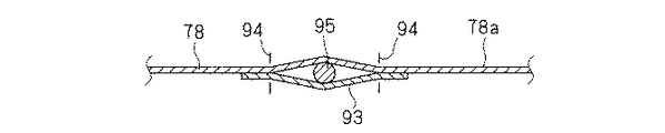
また、図7や図11に示されるように、第1カバー部78aの引き出し側端部には、当て布93および縫製部94を介して補強芯材95が幅方向沿って取り付けられており、シート部材78がシート巻取部79から引き出される際に、シート部材78の幅方向の全体にわたって引き出し力が均等に作用するように構成されている。   Further, as shown in FIG. 7 and FIG. 11, a reinforcing core member 95 is attached to the drawer side end portion of the first cover portion 78a along the width direction via a patch cloth 93 and a sewing portion 94. When the sheet member 78 is pulled out from the sheet take-up portion 79, the pulling force is configured to act uniformly over the entire width of the sheet member 78.

そして、ハッチバックドア14が閉じられた閉鎖状態では、一対のスライダ部60が一対のレール部30に沿って車両後方下端部に移動しており、トノカバー支持軸部71の後方に連結支持部76が位置する状態となって、トノボード部70は、略水平姿勢で面一状に展開する。より具体的には、トノボード部70は、その両側部がトノボード受部13bで載置状に支持されつつ、バックシートの背もたれ部分の上端部から後方に向けて延びる姿勢で面一状に展開して、荷室12の上方を覆う(図1〜図4参照)。この際、トノカバー部77においては、第2カバー部78bが巻き取られた状態となっており、トノボード部70の後端部とハッチバックドア14との間の空間を第1カバー部78aにより覆っている(図1〜図4参照)。   In the closed state in which the hatch back door 14 is closed, the pair of slider portions 60 are moved to the vehicle rear lower end portion along the pair of rail portions 30, and the connection support portion 76 is located behind the tonneau cover support shaft portion 71. The tonneau board portion 70 is deployed in a substantially horizontal posture and in a flush state. More specifically, the tonneau board portion 70 is unfolded in a flush manner with a posture extending from the upper end portion of the backrest portion of the back seat toward the rear while both sides thereof are supported by the tonneau board receiving portion 13b. Then, the upper part of the luggage compartment 12 is covered (see FIGS. 1 to 4). At this time, in the tonneau cover portion 77, the second cover portion 78b is wound up, and the space between the rear end portion of the tonneau board portion 70 and the hatch back door 14 is covered by the first cover portion 78a. (See FIGS. 1 to 4).

また、この状態からハッチバックドア14が開放操作されると、一対のスライダ部60が一対のレール部30に沿って車両前方上方に移動して、トノカバー支持軸部71の斜め上後方に連結支持部76が位置する状態となって、トノボード部70は、その後方部分をその前方部分上に折畳むようにして荷室12の上方を開放させる。より具体的には、最も前方の板状部72aに対してその後方の板状部72bを上方に持上げるように屈曲させると共に、その後方の板状部72c、72dを重ねるように折畳んで、前方の板状部72a、72b上に配設するようにして、荷室12の上方、特に、荷室12の上方後方部分を開放させるようにしている。   In addition, when the hatchback door 14 is opened from this state, the pair of slider parts 60 moves along the pair of rail parts 30 to the upper front side of the vehicle, and the connecting support part obliquely above and behind the tonneau cover support shaft part 71. In the state where 76 is located, the tonneau board part 70 opens the upper part of the luggage compartment 12 so that the rear part is folded on the front part. More specifically, the rearmost plate-like portion 72b is bent with respect to the foremost plate-like portion 72a so that the rearward plate-like portions 72c and 72d are overlapped with each other. The upper part of the cargo compartment 12, particularly the upper rear part of the cargo compartment 12, is arranged so as to be disposed on the front plate-like portions 72 a and 72 b.

ここで、トノボード部70の後方部分を前方部分上に折畳むようにする場合には、板状部72a、72b、72c、72dを屈曲部74で180゜で折曲げて完全に密着するように重ねる態様だけでなく、板状部72a、72b、72c、72dを屈曲部74で180゜よりも小さい角度で折曲げたような場合をも含む。例えば、略Z字状に折曲げられたような形態をも含む。このような折曲げ形態は、板状部72a、72b、72c、72dの分割態様、形状、大きさ等によって適宜決定され得る。要するに、トノボード部70の後方部分を前方部分上に折畳むようにする場合には、板状部72a、72b、72c、72dが屈曲部74で屈曲されていずれかの後方部分がそれよりも前方にある部分よりも上方に位置し、荷室12の上方が部分的(特に、後方部分)に開放されるようになる全ての折畳み態様が含まれる。   Here, when the rear portion of the tonneau board portion 70 is folded on the front portion, the plate-like portions 72a, 72b, 72c, 72d are folded at 180 ° by the bent portion 74 and overlapped so as to be completely adhered. This includes not only the mode but also the case where the plate-like portions 72a, 72b, 72c, 72d are bent at an angle smaller than 180 ° by the bent portion 74. For example, a form that is bent into a substantially Z shape is also included. Such a bending form can be appropriately determined depending on the division mode, shape, size, and the like of the plate-like portions 72a, 72b, 72c, 72d. In short, when the rear portion of the tonneau board portion 70 is folded on the front portion, the plate-like portions 72a, 72b, 72c, 72d are bent by the bent portion 74, and any one of the rear portions is further forward. All the folding modes that are located above a certain part and that allow the upper part of the luggage compartment 12 to be partially opened (particularly the rear part) are included.

一方、トノカバー部77側では、シート部材78がシート巻取部79から第2カバー部78bが引き出され、トノボード部70の後端部とハッチバックドア14との間に引っ張られた状態で配設される(図6参照)。このハッチバックドア14の開放操作に伴って第2カバー部78bが引き出される際に、第2カバー部78bとリアピラーガーニッシュ13cとは、切欠部78cによって相互干渉が防止される。   On the other hand, on the tonneau cover portion 77 side, the sheet member 78 is disposed in a state where the second cover portion 78b is pulled out from the sheet take-up portion 79 and pulled between the rear end portion of the tonneau board portion 70 and the hatch back door 14. (See FIG. 6). When the second cover part 78b is pulled out with the opening operation of the hatch back door 14, the second cover part 78b and the rear pillar garnish 13c are prevented from interfering with each other by the notch part 78c.

そして、この状態からハッチバックドア14を閉じると、トノボード部70は初期状態に展開し、シート部材78は第2カバー部78bがシート巻取部79に巻き取られ、荷室12空間を、トノボード部70とトノカバー部77によって覆った状態に戻される。なお、必要に応じて、トノカバー部77における第1カバー部78aをハッチバックドア14から取り外し、第2カバー部78bだけでなく、第1カバー部78aもシート巻取部79内に巻き取った収納状態とすることもできる。   When the hatch back door 14 is closed from this state, the tonneau board portion 70 is expanded to the initial state, the second cover portion 78b of the seat member 78 is taken up by the seat take-up portion 79, and the space in the luggage compartment 12 is transferred to the tonneau board portion. 70 and the tonneau cover part 77 return to the state covered. If necessary, the first cover portion 78a of the tonneau cover portion 77 is removed from the hatch back door 14, and the first cover portion 78a as well as the second cover portion 78b is wound in the sheet winding portion 79. It can also be.

<レール部、スライダ駆動機構部およびスライダ部>
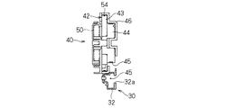
次に、レール部30、スライダ駆動機構部40およびスライダ部60について説明する。図12はレール部30、スライダ駆動機構部40およびスライダ部60を示す斜視図であり、図13は図12のXIII−XIII線断面図、図14は図12のXIV−XIV線断面図、図15は図12のXV−XV線断面図、図16はスライダ駆動機構部40およびスライダ部60部分を示す分解斜視図、図17はスライダ駆動機構部40部分を示す分解斜視図である。図18〜図20はレール部30に沿ってスライダ部60が移動する状態を示す説明図であり、図18はスライダ部60がレール部30の後端部に位置する状態、図19はスライダ部60がレール部30の中間部に位置する状態、図20はスライダ部60がレール部30の前端部に位置する状態をそれぞれ示している。
<Rail part, slider drive mechanism part and slider part>
Next, the rail part 30, the slider drive mechanism part 40, and the slider part 60 are demonstrated. 12 is a perspective view showing the rail section 30, the slider drive mechanism section 40, and the slider section 60. FIG. 13 is a sectional view taken along line XIII-XIII in FIG. 12, and FIG. 14 is a sectional view taken along line XIV-XIV in FIG. 15 is a sectional view taken along the line XV-XV in FIG. 12, FIG. 16 is an exploded perspective view showing the slider drive mechanism 40 and the slider 60 portion, and FIG. 17 is an exploded perspective view showing the slider drive mechanism 40 portion. 18-20 is explanatory drawing which shows the state which the slider part 60 moves along the rail part 30, FIG. 18 is the state in which the slider part 60 is located in the rear-end part of the rail part 30, FIG. FIG. 20 shows a state in which the slider portion 60 is positioned at the front end portion of the rail portion 30.

図2および図3、図12〜図15、図18〜図20に示すように、一対のレール部30は、両端が開口すると共に一側壁部に長尺状の開口32aが形成された略角筒状のレール本体部32を、それぞれ有している。そして、スライダ部60のスライダ移動体62が当該レール本体部32内をその長手方向に沿って往復移動可能に設けられている。   As shown in FIGS. 2, 3, 12 to 15, and 18 to 20, the pair of rail portions 30 are substantially square in which both ends are open and a long opening 32 a is formed on one side wall portion. Each has a tubular rail body 32. And the slider moving body 62 of the slider part 60 is provided in the said rail main-body part 32 so that a reciprocation is possible along the longitudinal direction.

また、レール本体部32には、適宜ブラケット34がネジ止等で取り付けられており、当該ブラケット34を介して、本レール部30が荷室12のリアピラーガーニッシュ13cの内側部分の側壁部13に取り付けられる。   Further, a bracket 34 is appropriately attached to the rail body portion 32 by screws or the like, and the rail portion 30 is attached to the side wall portion 13 of the inner portion of the rear pillar garnish 13c of the cargo compartment 12 via the bracket 34. It is done.

また、レール本体部32の両端部には、後述するプーリー体48を収容するプーリー収容部38が取り付けられており、当該プーリー体48はプーリー収容部38内に収容支持されることによって、レール本体部32の両端部で回転自在に支持される。   A pulley housing portion 38 that houses a pulley body 48 to be described later is attached to both ends of the rail body portion 32. The pulley body 48 is housed and supported in the pulley housing portion 38, whereby the rail body. It is rotatably supported at both ends of the portion 32.

このレール部30は、車両10後方から車両前方に向けて上向きに傾斜する姿勢で、側壁部13に取り付けられている。より具体的には、レール部30のレール本体部32の一端部を、上記のように面一状に展開させたトノボード部70の後端部の位置に配設すると共に、レール本体部32の他端部を、レール本体部32の一端部から車両10の斜め上前方に配設した斜め姿勢で、レール部30が側壁部13に取り付けられている(図3参照)。   The rail portion 30 is attached to the side wall portion 13 so as to incline upward from the rear of the vehicle 10 toward the front of the vehicle. More specifically, one end portion of the rail main body portion 32 of the rail portion 30 is disposed at the position of the rear end portion of the tonneau board portion 70 that is developed to be flush with each other as described above. The rail portion 30 is attached to the side wall portion 13 in an oblique posture in which the other end portion is disposed obliquely above and forward of the vehicle 10 from one end portion of the rail body portion 32 (see FIG. 3).

また、一対のスライダ部60は、一対のレール部30に沿って移動可能に構成されている。より具体的には、スライダ部60は、レール本体部32内を移動可能なスライダ移動体62と、連結支持部76の端部を支持可能な可動支持部68とを有している。   Further, the pair of slider portions 60 is configured to be movable along the pair of rail portions 30. More specifically, the slider portion 60 includes a slider moving body 62 that can move within the rail body portion 32, and a movable support portion 68 that can support the end portion of the connection support portion 76.

スライダ移動体62は、レール本体部32内を摺接移動するスライダ本体部63と、スライダ本体部63内を移動可能な内部移動体64と、内部移動体64を付勢する付勢部材としてのコイルバネ65とを有している。   The slider moving body 62 is a slider main body 63 that slides in the rail main body 32, an internal moving body 64 that can move in the slider main body 63, and a biasing member that biases the internal moving body 64. And a coil spring 65.

スライダ本体部63は、中間支持部63aを介して間隔をあけて支持された一対の支持端部63bと、支持端部63b間に設けられた棒状の内部スライダ支持部63cとを有している(図16、図18〜図20)。このスライダ本体部63は、レール本体部32内で両端部のプーリー収容部38間で移動自在とされている。   The slider main body 63 has a pair of support end portions 63b supported at an interval via an intermediate support portion 63a, and a rod-shaped internal slider support portion 63c provided between the support end portions 63b. (FIG. 16, FIGS. 18-20). The slider main body 63 is movable between the pulley accommodating portions 38 at both ends in the rail main body 32.

また、内部スライダ支持部63cが内部移動体64に形成された孔部に挿通されることで、内部移動体64が支持端部63b間で往復移動可能に支持されている。   Further, the internal slider support portion 63c is inserted into a hole formed in the internal moving body 64, so that the internal moving body 64 is supported so as to be reciprocally movable between the support end portions 63b.

さらに、内部スライダ支持部63cがコイルバネ65に挿通されて、当該コイルバネ65が車両10前方側の支持端部63bと内部移動体64との間に介在している。このコイルバネ65は、内部移動体64を車両10後方に付勢している。これにより、内部移動体64をレール部30の後方側の一定位置に配設した状態で、スライダ本体部63をレール部30のさらに後方側に移動させることができるようになっている(図18参照)。   Further, the internal slider support portion 63 c is inserted into the coil spring 65, and the coil spring 65 is interposed between the support end portion 63 b on the front side of the vehicle 10 and the internal moving body 64. The coil spring 65 biases the internal moving body 64 rearward of the vehicle 10. Thereby, the slider main body 63 can be moved further to the rear side of the rail portion 30 in a state where the internal moving body 64 is disposed at a fixed position on the rear side of the rail portion 30 (FIG. 18). reference).

可動支持部68は、内部移動体64と一体化されており、当該内部移動体64と共にレール部30の長手方向に沿って移動可能に構成されている。また、可動支持部68は、開口32aおよびリアピラーガーニッシュ13cに形成された開口を通じて荷室12内に突出すると共に、当該可動支持部68には、連結支持部76の端部を嵌め込むようにして支持可能な凹部68aが形成されている。そして、荷室12内で、当該連結支持部76が凹部68aに回転可能に支持されている。   The movable support portion 68 is integrated with the internal moving body 64 and is configured to be movable along the longitudinal direction of the rail portion 30 together with the internal moving body 64. The movable support portion 68 protrudes into the luggage compartment 12 through the opening formed in the opening 32a and the rear pillar garnish 13c, and can be supported by fitting the end portion of the connection support portion 76 into the movable support portion 68. A concave portion 68a is formed. And in the cargo compartment 12, the said connection support part 76 is rotatably supported by the recessed part 68a.

この可動支持部68および内部移動体64は、レール本体部32のうち車両10後方側に設けられた規制片34aによって、スライダ本体部63がレール本体部32のうち車両10の最後方位置に達するよりも手前で当該規制片34aに当接して停止するように位置規制されている。つまり、スライダ部60がレール部30に沿って車両10方向に移動する際、可動支持部68および内部移動体64が規制片34aによって位置規制された後、スライダ本体部63がさらに車両10後方に移動できるようになっている。   In the movable support 68 and the internal moving body 64, the slider main body 63 reaches the rearmost position of the vehicle 10 in the rail main body 32 by the restriction piece 34 a provided on the rear side of the vehicle 10 in the rail main body 32. The position is regulated so as to come into contact with and stop at the regulating piece 34a before. That is, when the slider portion 60 moves along the rail portion 30 in the direction of the vehicle 10, the position of the movable support portion 68 and the internal moving body 64 is restricted by the restriction piece 34 a, and then the slider body portion 63 is further moved rearward of the vehicle 10. It can be moved.

スライダ駆動機構部40は、伝達部42と、蓄力付勢部材としての渦巻ばね50とを有している。   The slider drive mechanism unit 40 includes a transmission unit 42 and a spiral spring 50 as a power storage biasing member.

伝達部42は、ハッチバックドア14の開動作を受けてスライダ部60を車両前方に移動可能に構成されている。より具体的には、伝達部42は、第1巻胴部43と第2巻胴部44と第2ワイヤ45とを有している。   The transmission part 42 is configured to be able to move the slider part 60 forward of the vehicle in response to the opening operation of the hatch back door 14. More specifically, the transmission portion 42 includes a first winding drum portion 43, a second winding drum portion 44, and a second wire 45.

第1巻胴部43および第2巻胴部44とは、同軸上で一体回転可能に連結されており、レール部30の長手方向中間部で、巻胴部収容ハウジング46を介して回転可能に支持されている。   The first and second drum sections 43 and 44 are coaxially connected to each other so as to be integrally rotatable, and can be rotated through the reel section housing housing 46 at the intermediate portion in the longitudinal direction of the rail section 30. It is supported.

第1巻胴部43は、略円盤状に形成されており、第1ワイヤ54を巻回可能に構成されている。ここで、第1ワイヤ54は、巻回可能な線状部材であり、その一端部はハッチバックドア14に連結されている。そして、ハッチバックドア14を開くと当該第1ワイヤ54の一端部が荷室12の開口外方に向けて引っ張られ、ハッチバックドア14を閉じると第1ワイヤ54に余剰長が生じるようになっている。また、第1ワイヤ54の他端部は第1巻胴部43に連結されており、ハッチバックドア14を閉じることによって生じる第1ワイヤ54の余剰長部分が第1巻胴部43に巻き戻し可能に構成されている。なお、ここでは、第1ワイヤ54は、荷室12の側壁部13の一部であるリアピラーガーニッシュ13c内を通って配設されている。   The first winding body 43 is formed in a substantially disc shape and is configured to be able to wind the first wire 54. Here, the first wire 54 is a linear member that can be wound, and one end thereof is connected to the hatchback door 14. When the hatchback door 14 is opened, one end portion of the first wire 54 is pulled toward the outside of the opening of the luggage compartment 12, and when the hatchback door 14 is closed, an excessive length is generated in the first wire 54. . Further, the other end portion of the first wire 54 is connected to the first winding drum portion 43, and the excessive length portion of the first wire 54 generated by closing the hatch back door 14 can be rewound onto the first winding drum portion 43. It is configured. In addition, the 1st wire 54 is arrange | positioned through the inside of the rear pillar garnish 13c which is a part of the side wall part 13 of the luggage compartment 12 here.

第2巻胴部44は、第1巻胴部43と連動して回転可能に構成されている。ここでは、第1巻胴部43は、第2巻胴部44と同軸上に一体的に連結されることで、当該第2巻胴部44と一体回転可能に構成されているが、その他、別々に回転可能に支持され、ギヤや無端環状ベルト等を介して連動回転可能とされた構成であってもよい。   The second winding drum portion 44 is configured to be rotatable in conjunction with the first winding drum portion 43. Here, the first winding drum portion 43 is configured to be integrally rotatable with the second winding drum portion 44 by being integrally connected to the second winding drum portion 44 in a coaxial manner. It may be configured such that it can be separately rotated and can be linked and rotated via a gear, an endless annular belt, or the like.

第2ワイヤ45は、ここでは2本用いられており、それぞれレール部30の両端側に回転自在に支持されたプーリー体48に巻き掛けられている。また、それぞれの第2ワイヤ45の一端部は、レール本体部32の側方を通ってその長手方向中間部で第2巻胴部44に巻き付けられると共に、それぞれの他端部がレール本体部32内を通ってスライダ部60の一対の支持端部63bにそれぞれ連結固定されている。そして、第2巻胴部44の回転に連動して、第2ワイヤ45がレール部30周りを回転するように動き、これに伴ってスライダ部60を引っ張るようにしてレール部30に沿って移動させる。なお、このような構成は、第2ワイヤ45として、1本のワイヤを用いることによっても実現できる。   Here, two second wires 45 are used, and are wound around pulley bodies 48 that are rotatably supported at both ends of the rail portion 30. Further, one end portion of each second wire 45 passes around the side of the rail body portion 32 and is wound around the second winding body portion 44 at the middle portion in the longitudinal direction, and each other end portion is wound on the rail body portion 32. They are connected and fixed to the pair of support end portions 63b of the slider portion 60 through the inside. Then, the second wire 45 moves so as to rotate around the rail portion 30 in conjunction with the rotation of the second winding drum portion 44, and moves along the rail portion 30 so as to pull the slider portion 60 accordingly. Let Such a configuration can also be realized by using a single wire as the second wire 45.

また、渦巻ばね50は、ハッチバックドア14の開放操作を受けて、第1ワイヤ54が第1巻胴部43から引き出されて当該第1巻胴部43が回転することで、第1巻胴部43を、第1ワイヤ54を巻き取る方向およびスライダ部60をレール部30の後方に付勢する方向への付勢力を蓄えるように構成されている。ここでは、渦巻ばね50の内周端部が第1巻胴部43の中心軸部に固定されると共に、渦巻ばね50の外周端部が巻胴部収容ハウジング46に固定されている。そして、第1ワイヤ54が引き出されるように第1巻胴部43が回転すると、これに連動してスライダ部60を車両10前方上方に移動させつつ、渦巻ばね50が縮径するように弾性変形し、反対方向への回転力、即ち、スライダ部60を車両後方下方に移動させる付勢力を蓄える。そして、ハッチバックドア14の閉操作により閉じられると、渦巻ばね50に蓄えられた付勢力を解放して、第1巻胴部43を反対方向に回転させて第1ワイヤ54を巻き取ると共に、これに連動して第2巻胴部44を同方向に回転させてスライダ部60を車両10後方下方に移動させる。   Further, the spiral spring 50 receives the opening operation of the hatch back door 14, the first wire 54 is pulled out from the first winding body 43, and the first winding body 43 rotates, so that the first winding body part is rotated. 43 is configured to store an urging force in a direction in which the first wire 54 is wound and in a direction in which the slider portion 60 is urged rearward of the rail portion 30. Here, the inner peripheral end portion of the spiral spring 50 is fixed to the central shaft portion of the first winding drum portion 43, and the outer peripheral end portion of the spiral spring 50 is fixed to the winding drum portion housing housing 46. Then, when the first winding body 43 rotates so that the first wire 54 is pulled out, the slider spring 60 is moved upward in front of the vehicle 10 in conjunction with this, and the spiral spring 50 is elastically deformed so that the diameter thereof is reduced. Then, the rotational force in the opposite direction, that is, the urging force for moving the slider portion 60 downward and rearward of the vehicle is stored. When the hatchback door 14 is closed, the urging force stored in the spiral spring 50 is released, the first winding body 43 is rotated in the opposite direction, and the first wire 54 is wound. In conjunction with this, the second winding drum portion 44 is rotated in the same direction to move the slider portion 60 rearward and downward of the vehicle 10.

なお、スライダ部60がレール部30に沿って後方に移動する際には、当該スライダ部60には、スライダ部60自体の自重やそれに掛かるトノボード部70等の自重等も作用する。このため、渦巻ばね50による付勢力は、それらの荷重をも考慮して、トノボード部70を展開できる程度の付勢力に設定される。それらの荷重を考慮すると、渦巻ばね50に要求される付勢力はそれほど大きくする必要はない。   In addition, when the slider part 60 moves back along the rail part 30, the weight of the slider part 60 itself, the weight of the tonneau board part 70, etc. applied to the slider part 60 act on the slider part 60. For this reason, the urging force by the spiral spring 50 is set to an urging force that allows the tonneau board portion 70 to be deployed in consideration of those loads. Considering these loads, the biasing force required for the spiral spring 50 does not need to be so large.

また、渦巻ばね50は、ハッチバックドア14が閉じられた閉鎖状態、即ち、スライダ部60が車両後方下端部に移動してトノボード部70が面一状に展開した状態でも、縮径するように付勢しており、第1巻胴部43を、第1ワイヤ54を巻き取る方向に付勢すると共に、第2巻胴部44を、スライダ部60をレール部30の後方に向けて移動させる方向に付勢している。   Further, the spiral spring 50 is attached so that the diameter of the spiral spring 50 is reduced even in a closed state where the hatchback door 14 is closed, that is, a state where the slider portion 60 moves to the lower rear end portion of the vehicle and the tonneau board portion 70 is deployed in a flush manner. The first winding body 43 is biased in the direction in which the first wire 54 is wound, and the second winding body 44 is moved in the direction in which the slider portion 60 is moved toward the rear of the rail portion 30. Is energized.

なお、第1ワイヤ54の一端部は、ワイヤ固定部55を介してハッチバックドア14に連結固定されている。   One end portion of the first wire 54 is connected and fixed to the hatchback door 14 via a wire fixing portion 55.

ワイヤ固定部55は、細長形状のハウジング55aと、ワイヤ端固定具55cと、付勢部材としてのコイルバネ55eとを備えており、ハッチバックドア14に取付固定されたドア側固定具55bを介してハッチバックドア14に連結固定される(図17、図21参照)。   The wire fixing portion 55 includes an elongated housing 55a, a wire end fixing tool 55c, and a coil spring 55e as an urging member, and is hatched back via a door side fixing tool 55b fixedly attached to the hatch back door 14. It is connected and fixed to the door 14 (see FIGS. 17 and 21).

ワイヤ端固定具55cは、棒状部分の一端部に棒状部分よりも太径の頭部が設けられた構成とされ、その他端部に第1ワイヤ54の一端部が連結固定されている。また、ワイヤ端固定具55cの棒状部分にコイルバネ55eが套嵌されている。また、ハウジング55aは、中空筺状に形成され、その内部に、ワイヤ端固定具55cが移動可能、かつ、コイルバネ55eが伸縮可能に配設されている。そして、第1ワイヤ54を引っ張ると、コイルバネ55eが縮んで、その縮んだ分だけ第1ワイヤ54がワイヤ固定部55から引き出される。また、第1ワイヤ54を引っ張る力を解除すると、コイルバネ55eが伸びて、その伸びた分だけ第1ワイヤ54がワイヤ固定部55内に引き戻されるようになっている。ハッチバックドア14側にはドア側固定具55bが、予め、取付固定されており、このドア側固定具55bにワイヤ固定部55のハウジング55aが着脱自在に連結固定されている。   The wire end fixing tool 55c is configured such that a head portion having a diameter larger than that of the rod-shaped portion is provided at one end portion of the rod-shaped portion, and one end portion of the first wire 54 is connected and fixed to the other end portion. A coil spring 55e is fitted over the rod-shaped portion of the wire end fixture 55c. Further, the housing 55a is formed in a hollow bowl shape, and a wire end fixing tool 55c is movable therein, and a coil spring 55e is extendable. When the first wire 54 is pulled, the coil spring 55e is contracted, and the first wire 54 is pulled out from the wire fixing portion 55 by the contracted amount. Further, when the force for pulling the first wire 54 is released, the coil spring 55e is extended, and the first wire 54 is pulled back into the wire fixing portion 55 by the extension. A door-side fixture 55b is attached and fixed in advance to the hatchback door 14, and the housing 55a of the wire fixing portion 55 is detachably connected and fixed to the door-side fixture 55b.

そして、ハッチバックドア14を開けた際に、スライダ部60がレール部30の前端部に停止し、第1巻胴部43からの第1ワイヤ54の引き出しが停止された状態で、ワイヤ固定部55から若干量の第1ワイヤ54の引き出しを可能にしている。   When the hatch back door 14 is opened, the slider portion 60 stops at the front end portion of the rail portion 30 and the drawing of the first wire 54 from the first winding drum portion 43 is stopped. Thus, a slight amount of the first wire 54 can be pulled out.

ここで、ハッチバックドア14の設計上の開閉範囲の上限および下限において、コイルバネ55eを適宜長収縮させた状態にすることで、ワイヤ端固定具55cがハウジング55a内における移動範囲の略中央に位置するように設定しておくとよい。これにより、ハッチバックドア14の実際の開閉範囲が、設計上の開閉範囲よりも大きい場合(例えば、+5゜大きい場合等)には、コイルバネ55eを収縮させて第1ワイヤ54を引き出して不足長分を補うことができる。一方、ハッチバックドア14の実際の開閉範囲が、設計上の開閉範囲よりも小さい場合(例えば、−5゜小さい場合等)には、コイルバネ55eが伸びることで、第1ワイヤ54を引き込んで弛みとなる余剰長分を解消することができる。この場合に、ハッチバックドア14を閉じた場合に生じた第1ワイヤ54の余剰長は、本ワイヤ固定部55にて優先的に引き戻すようにしてもよいし、第1巻胴部43にて優先的に巻き取るようにしてもよい。どちらを優先的に機能させるかは、コイルバネ55eや渦巻ばね50の付勢力によって適宜設定することができる。   Here, at the upper and lower limits of the design opening / closing range of the hatch back door 14, the coil spring 55e is appropriately lengthened and contracted so that the wire end fixing tool 55c is positioned at the approximate center of the movement range in the housing 55a. It is good to set it like this. As a result, when the actual opening / closing range of the hatchback door 14 is larger than the designed opening / closing range (for example, when + 5 ° is larger), the coil spring 55e is contracted and the first wire 54 is pulled out, so Can be supplemented. On the other hand, when the actual opening / closing range of the hatchback door 14 is smaller than the designed opening / closing range (for example, −5 ° smaller), the coil spring 55e is extended, and the first wire 54 is drawn and loosened. Can be eliminated. In this case, the surplus length of the first wire 54 generated when the hatch back door 14 is closed may be preferentially pulled back by the wire fixing portion 55, or may be given priority by the first winding drum portion 43. You may make it wind up. Which is preferentially functioned can be appropriately set by the biasing force of the coil spring 55e and the spiral spring 50.

<全体動作>
以上のように構成されたトノカバー装置20の全体動作について説明する。
<Overall operation>
The overall operation of the tonneau cover device 20 configured as described above will be described.

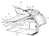
図21はハッチバックドア14が閉じた位置からヒンジ部回りに30゜回転して開いた状態を示す斜視図であり、図22は同状態を示す側面図であり、図23はハッチバックドア14が閉じた位置からヒンジ部回りに60゜回転して開いた状態を示す斜視図であり、図24は同状態を示す側面図であり、図25はハッチバックドア14が閉じた位置からヒンジ部回りに90゜回転して完全に開いた開放状態を示す斜視図であり、図26は同状態を示す側面図である。   FIG. 21 is a perspective view showing a state in which the hatchback door 14 is rotated 30 ° around the hinge portion from the closed position and opened, FIG. 22 is a side view showing the same state, and FIG. 23 is a diagram showing the hatchback door 14 closed. FIG. 24 is a side view showing the same state when rotated 60 ° around the hinge portion from the closed position, FIG. 24 is a side view showing the same state, and FIG. 25 is 90 around the hinge portion from the position where the hatchback door 14 is closed. FIG. 26 is a perspective view showing an open state that is completely opened after rotating by .degree., And FIG. 26 is a side view showing the same state.

まず、ハッチバックドア14が閉じた閉鎖状態では、図1〜図4、図21に示すように、スライダ部60は、レール部30の下端後端位置にあり、トノボード部70およびトノカバー部77は展開して荷室12の上方を完全に覆った状態となっている。また、第1ワイヤ54は、第1巻胴部43に巻回された状態となっている。さらに、この初期状態でも、渦巻ばね50の初期付勢力によって、スライダ部60のスライダ本体部63は、コイルバネ65の付勢力に抗してレール部30の後方側に付勢されており、内部移動体64は、一対の支持端部63bの略中間部に位置している(図18参照)。この初期状態では、スライダ部60は後方に付勢されている。この付勢力およびトノカバー部77の巻取方向の付勢力により、スライダ部60およびトノボード部70、トノカバー部77のがたつきが抑制されている。   First, in the closed state in which the hatchback door 14 is closed, as shown in FIGS. 1 to 4 and 21, the slider part 60 is at the lower end rear end position of the rail part 30, and the tonneau board part 70 and the tonneau cover part 77 are unfolded. Thus, the upper part of the cargo compartment 12 is completely covered. Further, the first wire 54 is wound around the first winding body 43. Further, even in this initial state, the slider body 63 of the slider portion 60 is urged to the rear side of the rail portion 30 against the urging force of the coil spring 65 by the initial urging force of the spiral spring 50, and the internal movement The body 64 is located at a substantially intermediate portion between the pair of support end portions 63b (see FIG. 18). In this initial state, the slider portion 60 is urged backward. Due to this urging force and the urging force of the tonneau cover portion 77 in the winding direction, rattling of the slider portion 60, the tonneau board portion 70 and the tonneau cover portion 77 is suppressed.

この状態で、利用者の操作等によってハッチバックドア14が開放操作されると、図21および図22に示すように、第1ワイヤ54が第1巻胴部43から引き出され、当該引き出しに伴い第1巻胴部43および第2巻胴部44が回転する。これにより、第2ワイヤ45が一対のプーリー体48周りに回転移動し、スライダ部60がレール部30に沿って車両10前方側の上方向に移動する。これにより、スライダ部60および当該スライダ部60に連結支持されたトノボード部70の後端部およびトノカバー部77のシート巻取部79が初期位置より上方に持上げられつつ、前方に移動する。すると、トノボード部70は、後方の板状部72b、72c、72d間の屈曲部74で屈曲される。この際、トノボード部70の後端部は、上方に持上げられつつ前方に移動するので、比較的小さい力でかつ円滑に、トノボード部70の後方部分をその前方部分上に配設するように、当該トノボード部70を屈曲させることができる。また、トノカバー部77のシート部材78における第2カバー部78bがシート巻取部79から徐々に引き出される。   In this state, when the hatchback door 14 is opened by a user operation or the like, as shown in FIGS. 21 and 22, the first wire 54 is pulled out from the first winding body 43, and the first wire 54 is pulled along with the drawing. The 1st drum part 43 and the 2nd drum part 44 rotate. As a result, the second wire 45 rotates around the pair of pulley bodies 48, and the slider portion 60 moves along the rail portion 30 in the upward direction on the front side of the vehicle 10. As a result, the slider portion 60 and the rear end portion of the tonneau board portion 70 connected and supported by the slider portion 60 and the sheet winding portion 79 of the tonneau cover portion 77 move upward while moving upward from the initial position. Then, the tonneau board portion 70 is bent at the bent portion 74 between the rear plate-like portions 72b, 72c, 72d. At this time, since the rear end portion of the tonneau board portion 70 is moved upward while being lifted upward, the rear portion of the tonneau board portion 70 is smoothly and relatively disposed with a relatively small force on the front portion. The tonneau board portion 70 can be bent. Further, the second cover portion 78 b of the sheet member 78 of the tonneau cover portion 77 is gradually pulled out from the sheet winding portion 79.

さらに、大きくハッチバックドア14が開動作されると、図23および図24に示すように、第1ワイヤ54がさらに大きく引き出され、スライダ部60がレール部30に沿ってさらに車両10前方側に移動する。これにより、トノボード部70の後端部およびトノカバー部77のシート巻取部79がさらに上方に持上げられつつ、前方に移動する。すると、トノボード部70は、後方の板状部72b、72c、72d間の屈曲部74でさらに大きく屈曲され、略Z字状に折畳まれるようになる。また、トノカバー部77の第2カバー部78bはシート巻取部79からさらに引き出される。   Further, when the hatch back door 14 is largely opened, as shown in FIGS. 23 and 24, the first wire 54 is further pulled out, and the slider portion 60 moves further along the rail portion 30 to the front side of the vehicle 10. To do. Accordingly, the rear end portion of the tonneau board portion 70 and the sheet winding portion 79 of the tonneau cover portion 77 are moved upward while being further lifted upward. Then, the tonneau board part 70 is further bent at the bent part 74 between the rear plate-like parts 72b, 72c, 72d, and is folded into a substantially Z-shape. Further, the second cover portion 78 b of the tonneau cover portion 77 is further pulled out from the sheet winding portion 79.

なお、図21〜図24に示すようにスライダ部60がレール部30の長手方向中間部に移動した状態では、図19に示すように、規制片34aによる可動支持部68および内部移動体64の位置規制が解除されるので、内部移動体64は、コイルバネ65の付勢力によって、後方の支持端部63b側に付勢された状態となる。   As shown in FIGS. 21 to 24, in the state where the slider portion 60 has moved to the intermediate portion in the longitudinal direction of the rail portion 30, as shown in FIG. 19, the movable support portion 68 and the internal moving body 64 by the restricting piece 34a. Since the position restriction is released, the internal moving body 64 is biased to the rear support end 63b side by the biasing force of the coil spring 65.

そして、ハッチバックドア14が完全に開いた開放状態になると、図25および図26に示すように、第1ワイヤ54がさらに大きく引き出され、スライダ部60がレール部30に沿って移動し、レール部30の車両10前端位置に移動する。これにより、トノボード部70の後端部およびトノカバー部77のシート巻取部79がさらに上方に持上げられつつ、前方に移動する。すると、トノボード部70は、上記状態から、前方の板状部72aとそれよりも後方の板状部72b間の屈曲部74でも屈曲され、トノボード部70は、その後方部分をその前方部分上に折畳むようにして荷室12の上方、特に、上方後部を開放させる。また、トノカバー部77の第2カバー部78bはシート巻取部79からより一層引き出される。   When the hatchback door 14 is fully opened, as shown in FIGS. 25 and 26, the first wire 54 is further drawn out, the slider portion 60 moves along the rail portion 30, and the rail portion The vehicle 30 moves to the front end position of the vehicle 10. Accordingly, the rear end portion of the tonneau board portion 70 and the sheet winding portion 79 of the tonneau cover portion 77 are moved upward while being further lifted upward. Then, from the above state, the tonneau board part 70 is also bent at the bent part 74 between the front plate-like part 72a and the rear plate-like part 72b, and the tonneau board part 70 has its rear part on its front part. The upper part of the luggage compartment 12, particularly the upper rear part, is opened in a folded manner. Further, the second cover part 78 b of the tonneau cover part 77 is further pulled out from the sheet winding part 79.

これにより、利用者は、荷室12の上方後方から荷室12内にアクセスして、当該荷室12内に対して荷物を出し入れできるようになる。   As a result, the user can access the luggage compartment 12 from above and behind the luggage compartment 12 and load / unload the luggage into / from the cargo compartment 12.

また、この状態では、トノボード部70の後端部は、一対のレール部30の上端部まで上がるだけである。トノボード部70は複数箇所で屈曲されているから、その最上端部は、従来のようにトノボードを二つ折りした場合よりも十分に低い。従って、トノボード部70の最上端部である後端部と荷室12の天井面との間に十分な空間を設けることができる。従って、シート部材78の先端部をハッチバックドア14から取り外せば、トノボード部70と荷室12の天井面との間の空間を利用して、リヤシートと荷室12の開口との間で荷物の受渡しを容易に行うことができる。   In this state, the rear end portion of the tonneau board portion 70 only rises to the upper end portions of the pair of rail portions 30. Since the tonneau board portion 70 is bent at a plurality of locations, the uppermost end portion thereof is sufficiently lower than the conventional case where the tonneau board is folded in half. Therefore, a sufficient space can be provided between the rear end portion, which is the uppermost end portion of the tonneau board portion 70, and the ceiling surface of the luggage compartment 12. Therefore, if the front end portion of the seat member 78 is removed from the hatchback door 14, the package is delivered between the rear seat and the opening of the cargo compartment 12 using the space between the tonneau board portion 70 and the ceiling surface of the cargo compartment 12. Can be easily performed.

また、製造上或いは組付上の誤差等が原因で、上記のようにハッチバックドア14を完全に開く手前で、スライダ部60がレール部30の最前方位置に達して停止した場合には、上記ワイヤ固定部55から若干第1ワイヤ54が引き出される。これにより、スライダ部60がレール部30の最前方位置に位置した状態からも、ハッチバックドア14をさらに開いて完全に開いた状態にすることができる。つまり、スライダ部60がレール部30の最前方位置に停止した状態における第1ワイヤ54の長さ寸法と、ハッチバックドア14が完全に開いた状態で必要とされる第1ワイヤ54の長さ寸法とが一致していない場合に、その誤差を吸収することができるようになっている。   In addition, when the slider portion 60 reaches the forefront position of the rail portion 30 and stops before the hatchback door 14 is completely opened as described above due to manufacturing or assembly errors, The first wire 54 is slightly pulled out from the wire fixing portion 55. Thereby, even from the state where the slider portion 60 is positioned at the forefront position of the rail portion 30, the hatchback door 14 can be further opened to be in a completely opened state. That is, the length dimension of the first wire 54 in a state where the slider portion 60 is stopped at the foremost position of the rail portion 30, and the length dimension of the first wire 54 required in a state where the hatch back door 14 is fully opened. The error can be absorbed when and do not match.

そして、ハッチバックドア14の開放状態からハッチバックドア14を閉鎖操作して、ハッチバックドア14を閉じると、渦巻ばね50に蓄勢された付勢力が解放され、渦巻ばね50の付勢力により第1巻胴部43および第2巻胴部44が回転する。そして、第1巻胴部43の回転により第1ワイヤ54が巻回される。また、第2巻胴部44の回転により、第2ワイヤ45が一対のプーリー体48周りを周回状に移動し、スライダ部60がレール部30に沿って車両10後方下方に移動する。これにより、スライダ部60および当該スライダ部60に連結支持されたトノボード部70の後端部およびトノカバー部77のシート巻取部79が下降しつつ後方に移動する。そして、スライダ部60がレール部30の後端の下端部位置に達すると、トノボード部70は面一状に展開し、シート部材78の第2カバー部78bはシート巻取部79内に巻き取られて、第1カバー部78aとトノボード部70により荷室12の上方を覆った状態に復帰する。   When the hatch back door 14 is closed from the opened state of the hatch back door 14 and the hatch back door 14 is closed, the urging force stored in the spiral spring 50 is released, and the urging force of the spiral spring 50 releases the first winding drum. The part 43 and the second winding body part 44 rotate. Then, the first wire 54 is wound by the rotation of the first winding body 43. Further, by the rotation of the second winding body portion 44, the second wire 45 moves around the pair of pulley bodies 48 in a circular manner, and the slider portion 60 moves along the rail portion 30 downward in the rear of the vehicle 10. Thereby, the rear end portion of the slider portion 60 and the tonneau board portion 70 connected and supported by the slider portion 60 and the sheet winding portion 79 of the tonneau cover portion 77 move downward while moving downward. When the slider portion 60 reaches the lower end position of the rear end of the rail portion 30, the tonneau board portion 70 expands in a flush manner, and the second cover portion 78 b of the sheet member 78 is taken up in the sheet take-up portion 79. Then, the first cover portion 78a and the tonneau board portion 70 return to the state where the upper portion of the cargo compartment 12 is covered.

なお、この状態では、渦巻ばね50の初期付勢力によって、スライダ部60のスライダ本体部63は、コイルバネ65の付勢力に抗してレール部30の後方側に付勢された状態に戻る。つまり、スライダ部60のうち可動支持部68および内部移動体64がレール部30の後端部位置の手前で規制片34aによって位置規制されて停止した状態で、スライダ本体部63を渦巻ばね50の付勢力によってさらに車両10後方に移動させ、第1巻胴部43および第2巻胴部44を回転させることができる。これにより、ハッチバックドア14を閉じてスライダ部60の可動支持部68および内部移動体64が停止した状態で、さらに第1ワイヤ54を巻き取ることができる。従って、可動支持部68および内部移動体64が後方位置に停止した状態における第1ワイヤ54の長さ寸法と、ハッチバックドア14が完全に閉じた状態で適切とされる第1ワイヤ54の長さ寸法とが一致していない場合に、その誤差を吸収できるようになっている。   In this state, due to the initial biasing force of the spiral spring 50, the slider body 63 of the slider portion 60 returns to the state of being biased to the rear side of the rail portion 30 against the biasing force of the coil spring 65. That is, in the slider portion 60, the movable support portion 68 and the internal moving body 64 are restricted by the restricting piece 34 a and stopped before the position of the rear end portion of the rail portion 30. It is possible to further move the vehicle 10 rearward by the urging force and rotate the first and second winding drums 43 and 44. Thereby, the first wire 54 can be further wound in a state where the hatch back door 14 is closed and the movable support portion 68 and the internal moving body 64 of the slider portion 60 are stopped. Accordingly, the length dimension of the first wire 54 in a state where the movable support portion 68 and the internal moving body 64 are stopped at the rear position, and the length of the first wire 54 that is appropriate when the hatchback door 14 is completely closed. If the dimensions do not match, the error can be absorbed.

以上のように構成されたトノカバー装置20によれば、ハッチバックドア14を開放操作すると、その開動作に伴って第1ワイヤ54がスライダ駆動機構部40から引き出され、スライダ部60がレール部30の下端部からレール部30に沿って車両10前方に向けて上方向に移動する。これにより、トノボード部70の後端部やトノカバー部77の前端部が前方上方に移動し、荷室12の上方が開放される。   According to the tonneau cover apparatus 20 configured as described above, when the hatch back door 14 is opened, the first wire 54 is pulled out from the slider drive mechanism 40 along with the opening operation, and the slider 60 is connected to the rail 30. It moves upward along the rail portion 30 from the lower end toward the front of the vehicle 10. Thereby, the rear end part of the tonneau board part 70 and the front end part of the tonneau cover part 77 move forward and upward, and the upper part of the luggage compartment 12 is opened.

また、ハッチバックドア14は上方に回動して開放操作されるため、シート部材78はハッチバックドア14の開動作に伴ってシート巻取部79から引き出されつつ移動する。この際、荷室12後方の対向するリアピラーガーニッシュ13cの間隔は、上方に向かって漸次狭くなっているが、引き出される第2カバー部78bには、リアピラーガーニッシュ13cに対向して切欠部78cが形成されており、操作時における相互干渉が防止される。   Further, since the hatch back door 14 is pivoted upward to be opened, the seat member 78 moves while being pulled out of the sheet take-up portion 79 with the opening operation of the hatch back door 14. At this time, the interval between the opposed rear pillar garnishes 13c at the rear of the cargo compartment 12 is gradually narrowed upward, but a cutout portion 78c is formed facing the rear pillar garnish 13c in the second cover portion 78b that is pulled out. This prevents mutual interference during operation.

このハッチバックドア14の開放状態においては、第1カバー部78aおよび第2カバー部78bがシート巻取部79から引き出された状態となっており、第2カバー部78bにおける最も幅狭とされた幅狭位置より、シート部材78の引き出し方向に向けて幅広となる広がり領域部Sにおいて、その両側部(図7の仮想線位置より外側方部分)に図10に示されるような垂れ下がり部100が生じるおそれがあるが、棒状芯材91によってその両側部分の下方への垂れ下がりが有効に防止される。   In the opened state of the hatch back door 14, the first cover portion 78a and the second cover portion 78b are pulled out from the sheet take-up portion 79, and the narrowest width in the second cover portion 78b. In the widened area S that becomes wider from the narrow position toward the drawing direction of the sheet member 78, a sag part 100 as shown in FIG. 10 is generated on both side parts (outside the imaginary line position in FIG. 7). Although there is a fear, the rod-shaped core member 91 can effectively prevent the both side portions from hanging downward.

なお、図7に示されるように、前記幅狭位置よりシート部材78の巻取方向に向けて幅広となる広がり領域部Tにおいても、その両側部(仮想線位置より外側部分)に垂れ下がり部が生じるおそれがあるが、シート巻取部79の巻芯79a(図9参照)によって巻き取られる際には、広がり領域部Tにおける幅広位置側から漸次巻き取られていくため、垂れ下がり部が生じていても、巻き取りにつれてその垂れ下がり部が元の平面状態に戻されながら巻き取られていくため、何ら支障が生じない。   Note that, as shown in FIG. 7, even in the widened region T that becomes wider from the narrow position toward the winding direction of the sheet member 78, there are hanging portions on both side portions (outer portions from the imaginary line position). Although it may occur, when the sheet is wound by the winding core 79a (see FIG. 9) of the sheet winding portion 79, the sheet is gradually wound from the wide position side in the spread region portion T, so that a drooping portion is generated. However, since the drooping portion is wound while being returned to the original flat state as it is wound, no trouble occurs.

そして、この開放状態よりハッチバックドア14を閉鎖操作すると、スライダ駆動機構部40の渦巻ばね50により、スライダ部60を車両10後方に移動させて、トノボード部70を面一状に展開させると共に、トノカバー部77の第2カバー部78bを巻き取った初期状態で荷室12の上方を覆うことができる。   When the hatchback door 14 is closed from this open state, the spiral spring 50 of the slider drive mechanism 40 moves the slider 60 to the rear of the vehicle 10 to deploy the tonneau board 70 in a flush manner, and tonneau cover. The upper portion of the luggage compartment 12 can be covered in the initial state where the second cover portion 78b of the portion 77 is wound up.

このハッチバックドア14の閉鎖操作時におけるトノカバー部77のシート部材78の巻き取りに際して、広がり領域部Sにおける垂れ下がり部100の発生が、棒状芯材91の保形作用によって有効に防止されているため、シート巻取部79内に第2カバー部78bが巻き取られる際に折り重なった状態での巻き込みがなく、巻取動作が円滑になされる。従って、切欠部78cの形状や大きさにかかわらず対応することが可能となり、シート部材78に折り癖が生じず、見栄えの向上が図れ、耐久性にも優れるという利点がある。   When winding up the sheet member 78 of the tonneau cover 77 during the closing operation of the hatch back door 14, the occurrence of the hanging portion 100 in the spreading region portion S is effectively prevented by the shape retaining action of the rod-shaped core 91. When the second cover portion 78b is wound into the sheet winding portion 79, there is no winding in a folded state, and the winding operation is smoothly performed. Accordingly, it is possible to cope with the cutout portion 78c regardless of the shape and size thereof, and there is an advantage that the sheet member 78 is not creased, the appearance is improved, and the durability is excellent.

また、シート部材78における第1カバー部78aと第2カバー部78bとを縫製する部分に垂れ下がり防止手段としての棒状芯材91を設けた構造としており、第1カバー部78aと第2カバー部78bとの縫製と同時に棒状芯材91を取り付けることができ、組み付け作業が容易で、その作業時間も短縮できる利点がある。   In addition, a rod-shaped core 91 as a sag-preventing means is provided at a portion of the sheet member 78 where the first cover portion 78a and the second cover portion 78b are sewn, and the first cover portion 78a and the second cover portion 78b are provided. The rod-shaped core material 91 can be attached simultaneously with the sewing, and there is an advantage that the assembling work is easy and the working time can be shortened.

さらに、トノカバー部77におけるシート巻取部79が、ハッチバックドア14の開放操作に連動して車両10上方向に移動されると共に、ハッチバックドア14の閉鎖操作に連動して車両10下方向に移動される構造とされており、ハッチバックドア14の開放状態で、シート巻取部79が上方に移動した位置にあるため、トノカバー部77を上方に大きく開放することができ、利用者にとって荷室12内が確認しやすく、荷物の積み卸し作業がより容易になるという利点がある。   Further, the sheet winding portion 79 in the tonneau cover portion 77 is moved upward in the vehicle 10 in conjunction with the opening operation of the hatch back door 14 and is moved in the downward direction in the vehicle 10 in conjunction with the closing operation of the hatch back door 14. With the hatch back door 14 in the open state, the seat take-up portion 79 is in a position moved upward, so that the tonneau cover portion 77 can be greatly opened upward, and the inside of the cargo compartment 12 for the user. This is advantageous in that it is easy to check and loading and unloading work becomes easier.

<変形例>
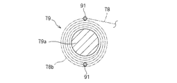
図27は第2の実施形態を示しており、シート巻取部79における巻芯79a部分の説明図である。即ち、トノカバー部77におけるシート部材78の第2カバー部78bに設けられる垂れ下がり防止手段としての棒状芯材91が、広がり領域部Sに、シート部材78の引き出し方向に離隔して複数(本実施形態では2本)位置に配置されると共に、シート巻取部79の巻芯79aに第2カバー部78bが巻き取られた際に、各棒状芯材91が巻芯79aの中心から放射方向に対して、互いに重ならない位置に配置された構造とされている。その他の構造は前記第1の実施形態と同様とされている。
<Modification>
FIG. 27 shows the second embodiment, and is an explanatory diagram of a core 79 a portion in the sheet winding unit 79. That is, a plurality of rod-shaped cores 91 as a drooping prevention means provided in the second cover portion 78b of the sheet member 78 in the tonneau cover portion 77 are separated in the extending region portion S in the drawing direction of the sheet member 78 (this embodiment). 2), and when the second cover portion 78b is wound around the core 79a of the sheet winding portion 79, each rod-shaped core 91 is moved from the center of the core 79a in the radial direction. Thus, the structure is arranged at a position where they do not overlap each other. Other structures are the same as those in the first embodiment.

従って、本実施形態においても上記同様の効果が得られると共に、複数の棒状芯材91によって、広がり領域部Sにおける垂れ下がりがより確実に防止できる。また、シート巻取部79にシート部材78が巻き取られた際の巻き径が大きくなるのを有効に防止でき、コンパクト化が図れる。   Therefore, in the present embodiment, the same effect as described above can be obtained, and the plurality of rod-shaped core members 91 can more reliably prevent the sagging in the spread region portion S. Further, it is possible to effectively prevent the winding diameter when the sheet member 78 is wound around the sheet winding portion 79 from being increased, and to achieve a compact size.

なお、上記各実施形態においては、トノカバー部77だけでなく、トノボード部70をも備えた構造を示しているが、トノボード部70を備えない構造であってもよい。この際、本実施形態では、トノカバー部77のシート巻取部79がハッチバックドア14の開閉操作に連動して上下方向に移動される構造を示しているが、シート巻取部79を荷室12側に着脱自在に位置決め状態で取り付ける構造であってもよい。   In addition, in each said embodiment, although the structure provided not only with the tonneau cover part 77 but the tonneau board part 70 was shown, the structure without the tonneau board part 70 may be sufficient. At this time, the present embodiment shows a structure in which the sheet winding portion 79 of the tonneau cover portion 77 is moved in the vertical direction in conjunction with the opening / closing operation of the hatch back door 14. A structure that is detachably attached to the side may be used.

また、垂れ下がり防止手段として棒状芯材91を用いた構造を示しているが、シート巻取部79によるシート部材78の巻き取りや引き出し操作に支障を生じないで、垂れ下がりを防止できる保形構造であればよい。   Further, the structure using the rod-shaped core member 91 is shown as means for preventing the sagging, but the shape retaining structure can prevent the sagging without causing any trouble in the winding and pulling operation of the sheet member 78 by the sheet winding unit 79. I just need it.

車両に設けられた車両用トノカバー装置を示す斜視説明図である。It is a perspective explanatory view showing the tonneau cover device for vehicles provided in vehicles. 同側面説明図である。FIG. 同内部構成を示す側面説明図である。It is side surface explanatory drawing which shows the internal structure. ハッチバックドアを閉じた状態を示す説明図である。It is explanatory drawing which shows the state which closed the hatch back door. ハッチバックドアを途中まで開いた状態を示す説明図である。It is explanatory drawing which shows the state which opened the hatch back door to the middle. ハッチバックドアを完全に開いた状態を示す説明図である。It is explanatory drawing which shows the state which opened the hatchback door completely. トノカバー部材および後部トノカバー部材を示す平面図である。It is a top view which shows a tonneau cover member and a rear part tonneau cover member. トノカバー部材および後部トノカバー部材を示す側面図である。It is a side view which shows a tonneau cover member and a rear part tonneau cover member. 同要部拡大断面図である。It is the principal part expanded sectional view. 図7のX−X線断面図である。It is the XX sectional view taken on the line of FIG. 図7のXI−XI線断面図である。It is the XI-XI sectional view taken on the line of FIG. レール部、スライダ駆動機構部およびスライダ部を示す斜視図である。It is a perspective view which shows a rail part, a slider drive mechanism part, and a slider part. 図12のXIII−XIII線断面図である。It is the XIII-XIII sectional view taken on the line of FIG. 図12のXIV−XIV線断面図である。It is the XIV-XIV sectional view taken on the line of FIG. 図12のXV−XV線断面図である。It is the XV-XV sectional view taken on the line of FIG. スライダ駆動機構部およびスライダ部を示す分解斜視図である。It is a disassembled perspective view which shows a slider drive mechanism part and a slider part. スライダ駆動機構部を示す分解斜視図である。It is a disassembled perspective view which shows a slider drive mechanism part. スライダ部がレール部の下端部に位置する状態を示す説明図である。It is explanatory drawing which shows the state in which a slider part is located in the lower end part of a rail part. スライダ部がレール部の中間部に位置する状態を示す説明図である。It is explanatory drawing which shows the state in which a slider part is located in the intermediate part of a rail part. スライダ部がレール部の上端部に位置する状態を示す説明図である。It is explanatory drawing which shows the state in which a slider part is located in the upper end part of a rail part. ハッチバックドアが閉じた位置から30゜回転して開いた状態を示す斜視図である。It is a perspective view which shows the state which rotated 30 degrees from the position which the hatchback door closed, and opened. 同側面図である。It is the same side view. ハッチバックドアが閉じた位置から60゜回転して開いた状態を示す斜視図である。It is a perspective view which shows the state which rotated 60 degrees from the position which the hatchback door closed, and opened. 同側面図である。It is the same side view. ハッチバックドアが完全に開いた状態を示す斜視図である。It is a perspective view which shows the state which the hatchback door opened completely. 同側面図である。It is the same side view. 変形例を示す要部説明図である。It is principal part explanatory drawing which shows a modification.

符号の説明Explanation of symbols

10 車両
12 荷室
13 側壁部
13c リアピラーガーニッシュ
14 ハッチバックドア
20 トノカバー装置
30 レール部
40 スライダ駆動機構部
60 スライダ部
70 トノボード部
77 トノカバー部
78 シート部材
78a 第1カバー部
78b 第2カバー部
78c 切欠部
79 シート巻取部
79a 巻芯
90 縫製部
91 棒状芯材
DESCRIPTION OF SYMBOLS 10 Vehicle 12 Cargo compartment 13 Side wall part 13c Rear pillar garnish 14 Hatch back door 20 Tonneau cover device 30 Rail part 40 Slider drive mechanism part 60 Slider part 70 Tonneau board part 77 Tonneau cover part 78 Seat member 78a 1st cover part 78b 2nd cover part 78c Notch part 79 Sheet winding part 79a Winding core 90 Sewing part 91 Bar-shaped core material

Claims (4)

対向するリアピラーガーニッシュの間隔が、車両の下方から上方に向かって荷室幅より漸次狭く形成されているハッチバックタイプの車両に設けられ、ハッチバックドアの操作に連動して引き出しおよび巻き取り可能とされた車両用トノカバー装置において、
車両の荷室を覆って引き出し側端部が前記ハッチバックドアに連結されると共にハッチバックドア開放状態で前記リアピラーガーニッシュと対向する両側部分に切欠部が形成されたトノカバーシートと、荷室に取り付けられると共にトノカバーシートの基部が連結されてトノカバーシートを巻き取る方向に付勢するシート巻取部とを備え、
前記切欠部により形成された幅狭位置よりトノカバーシートの引き出し方向に向けて幅広となる広がり領域部に垂れ下がり防止手段を設けたことを特徴とする車両用トノカバー装置。
The distance between the opposing rear pillar garnishes is provided in hatchback type vehicles that are gradually narrower than the cargo compartment width from the bottom to the top of the vehicle, and can be pulled out and wound in conjunction with the operation of the hatchback door. In the vehicle tonneau cover device,
A tonneau cover sheet that covers the cargo compartment of the vehicle and has a drawer side end connected to the hatchback door and has a notch formed on both sides facing the rear pillar garnish when the hatchback door is open, and is attached to the cargo compartment A base part of the tonneau cover sheet is connected, and a sheet winding part that urges the tonneau cover sheet in a direction to wind up the tonneau cover sheet,
A vehicular tonneau cover device, characterized in that a drooping prevention means is provided in a widened area portion that becomes wider from the narrow position formed by the cutout portion in the pulling out direction of the tonneau cover sheet.
請求項1に記載の車両用トノカバー装置において、
前記トノカバーシートは、前記ハッチバックドアの閉鎖状態で前記シート巻取部から引き出されている第1カバー部と、該第1カバー部に縫製されて連続し、ハッチバックドアの開放操作により引き出されると共に前記切欠部が形成されている第2カバー部とからなり、
前記第1カバー部と前記第2カバー部とを縫製する部分に前記垂れ下がり防止手段を設けたことを特徴とする車両用トノカバー装置。
The vehicle tonneau cover device according to claim 1,
The tonneau cover sheet is continuous with the first cover part pulled out from the sheet take-up part in the closed state of the hatch back door, and is sewn on the first cover part, and is pulled out by the opening operation of the hatch back door. A second cover part formed with a notch,
A tonneau cover device for a vehicle, wherein the sag prevention means is provided at a portion where the first cover portion and the second cover portion are sewn.
請求項1または請求項2に記載の車両用トノカバー装置において、
前記シート巻取部が、ハッチバックドアの開放操作に連動して車両上方向に移動されると共に、ハッチバックドアの閉鎖操作に連動して車両下方向に移動されることを特徴とする車両用トノカバー装置。
In the tonneau cover device for vehicles according to claim 1 or 2,
The tonneau cover device for a vehicle, wherein the seat winder is moved upward in the vehicle in conjunction with the opening operation of the hatch back door and is moved in the downward direction in conjunction with the closing operation of the hatch back door. .
請求項1ないし請求項3のいずれかに記載の車両用トノカバー装置において、
前記垂れ下がり防止手段は、前記トノカバーシートの幅方向に沿って装着された棒状芯材からなり、
前記棒状芯材は前記トノカバーシートの引き出し方向に離隔して複数位置に配置されると共に、前記シート巻取部の巻芯に対してトノカバーシートが巻き取られた際に、各棒状芯材が互いに重ならない位置に配置されていることを特徴とする車両用トノカバー装置。
The vehicle tonneau cover device according to any one of claims 1 to 3,
The sagging prevention means is composed of a rod-shaped core member attached along the width direction of the tonneau cover sheet,
The rod-shaped core members are arranged at a plurality of positions apart in the pulling-out direction of the tonneau cover sheet, and when the tonneau cover sheet is wound around the core of the sheet winding portion, the rod-shaped core members are mutually connected. A tonneau cover device for a vehicle, wherein the tonneau cover device is arranged at a position that does not overlap.
JP2007233971A 2007-09-10 2007-09-10 Tonneau cover device for vehicle Active JP5281260B2 (en)

Priority Applications (1)

Application Number Priority Date Filing Date Title
JP2007233971A JP5281260B2 (en) 2007-09-10 2007-09-10 Tonneau cover device for vehicle

Applications Claiming Priority (1)

Application Number Priority Date Filing Date Title
JP2007233971A JP5281260B2 (en) 2007-09-10 2007-09-10 Tonneau cover device for vehicle

Publications (2)

Publication Number Publication Date
JP2009062017A true JP2009062017A (en) 2009-03-26
JP5281260B2 JP5281260B2 (en) 2013-09-04

Family

ID=40557003

Family Applications (1)

Application Number Title Priority Date Filing Date
JP2007233971A Active JP5281260B2 (en) 2007-09-10 2007-09-10 Tonneau cover device for vehicle

Country Status (1)

Country Link
JP (1) JP5281260B2 (en)

Cited By (1)

* Cited by examiner, † Cited by third party
Publication number Priority date Publication date Assignee Title
WO2011052362A1 (en) * 2009-10-30 2011-05-05 芦森工業株式会社 Cover apparatus for vehicle

Citations (5)

* Cited by examiner, † Cited by third party
Publication number Priority date Publication date Assignee Title
JPS5551632Y2 (en) * 1976-01-19 1980-12-01
JPS6319448U (en) * 1986-07-24 1988-02-08
JPH0971187A (en) * 1995-09-08 1997-03-18 Nhk Spring Co Ltd Tonneau cover for automobile
JPH11139211A (en) * 1997-11-10 1999-05-25 Kasai Kogyo Co Ltd Car tonneau cover
JP2007196939A (en) * 2006-01-30 2007-08-09 Mazda Motor Corp Tonneau cover device

Patent Citations (5)

* Cited by examiner, † Cited by third party
Publication number Priority date Publication date Assignee Title
JPS5551632Y2 (en) * 1976-01-19 1980-12-01
JPS6319448U (en) * 1986-07-24 1988-02-08
JPH0971187A (en) * 1995-09-08 1997-03-18 Nhk Spring Co Ltd Tonneau cover for automobile
JPH11139211A (en) * 1997-11-10 1999-05-25 Kasai Kogyo Co Ltd Car tonneau cover
JP2007196939A (en) * 2006-01-30 2007-08-09 Mazda Motor Corp Tonneau cover device

Cited By (1)

* Cited by examiner, † Cited by third party
Publication number Priority date Publication date Assignee Title
WO2011052362A1 (en) * 2009-10-30 2011-05-05 芦森工業株式会社 Cover apparatus for vehicle

Also Published As

Publication number Publication date
JP5281260B2 (en) 2013-09-04

Similar Documents

Publication Publication Date Title
US7503374B2 (en) Sunshade actuation device
US7287796B2 (en) Integrated cargo net for a vehicle
US8011711B2 (en) Tonneau cover device for vehicle
JP5062043B2 (en) Deck board and deck board mounting structure
CN101380925B (en) Tonneau cover device for vehicle
JP5007570B2 (en) Vehicle tonneau cover device
JP2010076571A (en) Luggage compartment structure of vehicle
JP4694977B2 (en) Deck board
JP5281260B2 (en) Tonneau cover device for vehicle
JP2009062021A (en) Tonneau board device
JP5340888B2 (en) Vehicle cover device
JP5161675B2 (en) Shielding device
JP5100267B2 (en) Tonneau board
JP4979520B2 (en) Tonneau cover device
JP2012111491A (en) Tonneau board and method of fabricating tonneau board
KR101394140B1 (en) Cargo screen device
JP5577725B2 (en) Vehicle tonneau cover device
JP2009062015A (en) Tonneau cover device for vehicle
JP2007196938A (en) Vehicle tonneau cover device
JP2008179322A (en) Vehicle tonneau cover device
JP4876961B2 (en) Sun visor
JP7845096B2 (en) seat belt device
JP3376447B2 (en) Folding roof opening and closing device for vehicles
JP6075135B2 (en) Sunshade equipment
JP3927025B2 (en) Roof storage structure

Legal Events

Date Code Title Description
A621 Written request for application examination

Free format text: JAPANESE INTERMEDIATE CODE: A621

Effective date: 20100714

A977 Report on retrieval

Free format text: JAPANESE INTERMEDIATE CODE: A971007

Effective date: 20120314

A131 Notification of reasons for refusal

Free format text: JAPANESE INTERMEDIATE CODE: A131

Effective date: 20120321

A02 Decision of refusal

Free format text: JAPANESE INTERMEDIATE CODE: A02

Effective date: 20121120

A521 Request for written amendment filed

Free format text: JAPANESE INTERMEDIATE CODE: A523

Effective date: 20130220

A911 Transfer to examiner for re-examination before appeal (zenchi)

Free format text: JAPANESE INTERMEDIATE CODE: A911

Effective date: 20130227

TRDD Decision of grant or rejection written
A01 Written decision to grant a patent or to grant a registration (utility model)

Free format text: JAPANESE INTERMEDIATE CODE: A01

Effective date: 20130430

A61 First payment of annual fees (during grant procedure)

Free format text: JAPANESE INTERMEDIATE CODE: A61

Effective date: 20130524

R150 Certificate of patent or registration of utility model

Free format text: JAPANESE INTERMEDIATE CODE: R150

Ref document number: 5281260

Country of ref document: JP

Free format text: JAPANESE INTERMEDIATE CODE: R150

R250 Receipt of annual fees

Free format text: JAPANESE INTERMEDIATE CODE: R250

R250 Receipt of annual fees

Free format text: JAPANESE INTERMEDIATE CODE: R250

R250 Receipt of annual fees

Free format text: JAPANESE INTERMEDIATE CODE: R250

R250 Receipt of annual fees

Free format text: JAPANESE INTERMEDIATE CODE: R250

R250 Receipt of annual fees

Free format text: JAPANESE INTERMEDIATE CODE: R250

R250 Receipt of annual fees

Free format text: JAPANESE INTERMEDIATE CODE: R250

R250 Receipt of annual fees

Free format text: JAPANESE INTERMEDIATE CODE: R250

R250 Receipt of annual fees

Free format text: JAPANESE INTERMEDIATE CODE: R250

R250 Receipt of annual fees

Free format text: JAPANESE INTERMEDIATE CODE: R250

R250 Receipt of annual fees

Free format text: JAPANESE INTERMEDIATE CODE: R250