JP2009070077A - Electronic tag attachment tool for metal objects - Google Patents
Electronic tag attachment tool for metal objects Download PDFInfo
- Publication number
- JP2009070077A JP2009070077A JP2007236895A JP2007236895A JP2009070077A JP 2009070077 A JP2009070077 A JP 2009070077A JP 2007236895 A JP2007236895 A JP 2007236895A JP 2007236895 A JP2007236895 A JP 2007236895A JP 2009070077 A JP2009070077 A JP 2009070077A
- Authority
- JP
- Japan
- Prior art keywords
- electronic tag
- holder
- support member
- metal
- support
- Prior art date
- Legal status (The legal status is an assumption and is not a legal conclusion. Google has not performed a legal analysis and makes no representation as to the accuracy of the status listed.)
- Withdrawn
Links
Images


Abstract
Description
この発明は、金属製対象物に電子タグを取り付けるための取付器具に関する。 The present invention relates to an attachment device for attaching an electronic tag to a metal object.
大量の情報を記録させた電子タグは、ワイヤレス式リーダによる電磁波通信によって、そこに記録された情報を簡易に読みとることができ、工場における治具金型や部品の管理あるいは倉庫における商品の在庫管理等はもとより、スーパーやコンビニ店舗のレジなどあらゆる分野で汎用されている。 Electronic tags with a large amount of information recorded can be easily read by electromagnetic wave communication using a wireless reader, managing jig molds and parts in a factory, or managing inventory of goods in a warehouse. Is widely used in various fields such as supermarkets and cash registers at convenience stores.
このような電子タグが工場の部品管理に用いられる場合、工場における部品は積み重ね自在のトートボックスや搬送用のパレットなどの収納具に収納されることも多く、そのようなケースでは、それらの収納具に取り付けられる。 When such an electronic tag is used for factory parts management, parts in the factory are often stored in storage devices such as stackable tote boxes and transport pallets. Attached to the tool.
ところで、建設機械や自動車等、重量構造物の製造工場にあっては、その部品の収納具が堅固な金属製の場合も多く、そのような収納具にそのまま電子タグを取り付けると、収納具の金属板が電磁波通信の障害となることがある。そこで、このような問題に対して、特開2006−85322では図5に示すような取付器具が提案されている。これは、電子タグ4に支持部材5を取り付け、その支持部材5を収納具(取付対象物)に固着することで、電子タグ4を収納具等の対象物から距離を置いて配置させ、それによって電磁波通信の障害を防ごうとするものである。
By the way, in heavy machinery manufacturing factories such as construction machines and automobiles, the parts are often made of solid metal, and when an electronic tag is attached to such a storage as it is, The metal plate may be an obstacle to electromagnetic wave communication. In view of this, Japanese Patent Application Laid-Open No. 2006-85322 proposes an attachment device as shown in FIG. This is because the
前記従来技術は、電磁波通信の障害という問題を排除するという点では有意義な器具であったが、その一方で、使い勝手が悪いという問題があり、また取付器具の再利用性が困難となり、その利用コストも低く抑えることが困難となる問題等がある。 The prior art was a significant instrument in terms of eliminating the problem of electromagnetic communication failure, but on the other hand, there was a problem of poor usability, and the reusability of the mounting instrument became difficult, and its use There is a problem that it is difficult to keep costs low.
すなわち、前記取付器具は、電子タグの支持部材を直接固着したり、クリップや針等の接続手段を用いて取り付けるものとなっている。電子タグの装着は、決められた所定の収納具に間違わずに取り付ける必要があり、また取付数も多量の場合が多いので、前記取付器具による装着作業はきわめて煩雑となる。 That is, the attachment device is to attach the supporting member of the electronic tag directly, or attach it using connection means such as a clip or a needle. It is necessary to attach the electronic tag without making a mistake in the predetermined storage device, and since there are many cases where the number of attachments is large, the attachment work by the attachment device becomes extremely complicated.
また、取付器具の支持部材が収納具に直接固着(例えば接着剤による接着)されるような態様だと、支持部材を取り外した後に取付器具の再利用ができず、使い捨てとせざるを得ない。さらに、電子タグを再利用する場合には、新たな記録を上書きするため取付器具から切り離す作業を要し、きわめて煩雑となるばかりか、この場合も取付器具を使い捨てとしなければならなかった。 In addition, if the support member of the attachment device is directly fixed to the storage device (for example, adhesion by an adhesive), the attachment device cannot be reused after the support member is removed, and it must be disposable. Further, when the electronic tag is reused, it is necessary to separate it from the mounting device in order to overwrite a new record, which is extremely complicated. In this case as well, the mounting device must be made disposable.
この発明は、従来技術の以上のような問題に鑑み創案されたもので、取付対象物が金属であっても何の問題もなく電子タグを利用できる取付器具であって、しかもその脱着がきわめて容易で、かつ取付器具の再利用が可能であり、製造コスト及び利用コストもきわめて低廉で済む取付器具を提供しようとするものである。 The present invention was devised in view of the above-described problems of the prior art, and is an attachment that can use an electronic tag without any problems even if the object to be attached is a metal. It is an object of the present invention to provide an attachment device that is easy and can be reused, and that can be manufactured and used at a very low cost.
このため、この発明に係る金属製対象物用電子タグ取付器具は、電子タグが挿脱自在な絶縁製ホルダと、該ホルダをその先端で支持する所定長さの絶縁製支持部材とを備え、該支持部材の基端部に磁性体を配置させたことを特徴とする。 For this reason, the electronic tag mounting tool for a metal object according to the present invention includes an insulating holder in which the electronic tag can be inserted and removed, and an insulating support member having a predetermined length for supporting the holder at the tip thereof. A magnetic material is disposed at the base end of the support member.
この発明では、支持部材の基端部に磁性体が配置されているので、その基端部は磁力によって金属製対象物に簡単に吸着固定され、また容易に取り外すこともできる。 In the present invention, since the magnetic body is disposed at the base end portion of the support member, the base end portion is easily attracted and fixed to the metal object by a magnetic force, and can be easily removed.
次に、電子タグを利用する際は、支持部材基端部の磁性体を金属製対象物に吸着させた取付状態で、支持部材先端のホルダに電子タグを挿入するか、あらかじめ支持部材のホルダに電子タグを挿入した状態で吸着さえすれば良く、いずれにしてもきわめて簡単に電子タグの装着が完了する。電子タグの記録読み取り作業が終了し、その後再度の読み取りがないのであれば、電子タグをホルダから抜き取るか、取付器具自体を金属対象物から外せば良い。これらの作業もきわめて簡易に行える。回収した取付器具及び電子タグはもちろん再利用が可能である。 Next, when the electronic tag is used, the electronic tag is inserted into the holder at the tip of the support member with the magnetic body at the base end of the support member attached to the metal object, or the holder of the support member in advance. It is only necessary to adsorb the electronic tag with the electronic tag inserted therein, and in any case, the mounting of the electronic tag can be completed very easily. If the record reading operation of the electronic tag is completed and there is no subsequent reading, the electronic tag may be removed from the holder or the mounting tool itself may be removed from the metal object. These operations can be performed very easily. Of course, the collected fixtures and electronic tags can be reused.
なお、電子タグの取付対象が金属製であるものの、ホルダが所定長さの支持部材を介して対象物に取り付けられており、電子タグはその対象物から離れて位置することになるので、リーダによる記録読みとりの際に、電磁波通信の障害が生じることもない。 Although the attachment target of the electronic tag is made of metal, the holder is attached to the object via a support member having a predetermined length, and the electronic tag is located away from the object. When reading or recording data, there is no problem with electromagnetic wave communication.
以上のように、本発明によれば、金属対象物に対して取付器具をきわめて簡単に脱着できる。また、脱着自在なので、一度利用した取付器具をその後何度でも利用できる。しかも、ホルダに挿入する電子タグを入れ替えることで、多様な種類の電子タグの取付器具として利用できる。それゆえ、従来の取付器具と比較して、製造コスト及び利用コストがきわめて低廉で済む。 As described above, according to the present invention, the fixture can be attached to and detached from the metal object very easily. Moreover, since it is detachable, the once used fixture can be used any number of times thereafter. Moreover, by replacing the electronic tag inserted into the holder, it can be used as an attachment device for various types of electronic tags. Therefore, compared with the conventional fixture, manufacturing cost and utilization cost are very low.
もちろん、取付器具は、ホルダと支持部材が絶縁製素材より形成され、またホルダが支持部材によって金属対象物から離れた位置となるので、電子タグの記録情報をリーダで読み取る際、電磁波通信の障害となるようなこともない。 Of course, since the holder and the support member are made of an insulating material, and the holder is positioned away from the metal object by the support member, when the recorded information of the electronic tag is read by the reader, it is an obstacle to electromagnetic wave communication. There is no such thing as.
本発明に係る具体的形態の一例を図面に基づき説明する。以下の例は、いずれもUHF帯(高周波)のワイヤレス通信によって、リーダ(図示なし)から記録を読みとられるICタグ(電子タグ)の取付器具であり、特に本形態例では、作業機械の工場において、作業機械の部品を収納する金属製トートボックス(金属製対象物)に取り付けることを想定した取付器具である。なお、以下の例はあくまで一例であって、本形態例を他の金属対象物に取り付けても良いのは当然であるし、またその取付器具自体の形態が以下の形態に限定されないこともまた当然である。 An example of a specific form according to the present invention will be described with reference to the drawings. Each of the following examples is a mounting tool for an IC tag (electronic tag) that can be read from a reader (not shown) by wireless communication in the UHF band (high frequency). 1 is an attachment device that is assumed to be attached to a metal tote box (metal object) that accommodates parts of the work machine. The following example is merely an example, and it is natural that the present embodiment may be attached to other metal objects, and the form of the attachment device itself is not limited to the following form. Of course.
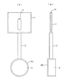
図1に第1形態例を示す。本形態例は、ICタグ用ホルダ1と、該ホルダ1を支持する支持体2とから構成され、該支持体2の基端部には、円盤状の磁石3が取り付けられる。
FIG. 1 shows a first embodiment. This embodiment is composed of an
前記ホルダ1は、絶縁ゴム系プラスチック製のカードケース状であり、上辺にはICタグの挿入口10が設けられるとともに、前面中央には、上下に伸びるICタグ取出し用ガイド溝11が穿設される。
The
前記支持体2は所定長さの棒状体から構成され、前記ホルダ1と同様に、絶縁ゴム系プラスチック製である。この支持体2は、例えば図4(a)に示すような曲折自在なフレキシブルチューブ20を用いたり、同図(b)に示すように、本体を複数に分断したうえ各分断部分21を枢軸ピン22で連結して、その本体を曲折自在としたりして、ホルダ1(ICタグ)の位置を最適な場所に移動させるようにしても良い。
The
前記マグネット3は、円盤状ホルダ30に嵌め込まれており、その円盤状ホルダ30の円周部に、前記支持体2の基端部が固着されている。これにより、マグネット3が金属製トートボックスに吸着されると、ICタグ用ホルダ1は、取付面の接線方向上で、かつ取付面から支持体2の長さ分離れた位置に配置される。
The
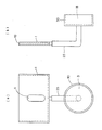
図2に第2形態例を示す。本形態例は、基本的に前記第1形態例とほぼ同様の構造であるが(共通する構成は同一の符号を付す。以下同じ)、マグネット3が嵌め込まれる前記円盤状ホルダ30に対する支持体2の取り付け方が前記第1形態例と異なっている。すなわち、図示のように円盤状ホルダ30の円盤面中央に支持体2基端部が取り付けられる。これにより、本形態例では、ICタグ用ホルダ1が、取付面に対し垂直方向上の任意位置に離れる態様となる。
FIG. 2 shows a second embodiment. The present embodiment is basically the same structure as the first embodiment (common configurations are given the same reference numerals; the same applies hereinafter), but the
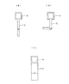
図3に第3形態例を示す。本形態例は、基本的に前記第2形態例とほぼ同様の構造であるが、支持体23がその中間部において直角に曲折している構造となっている点が前記第2形態例と異なっている。この支持体23の曲折により、取付面の接線方向と平行線上で、かつ取付面から支持体23の長さ分離れた位置に配置される。
FIG. 3 shows a third embodiment. The present embodiment is basically the same structure as the second embodiment, but is different from the second embodiment in that the
以上の形態例では、いずれも支持体2,23基端部のマグネット3を金属製トートボックス(図示なし)に当接させれば磁力で吸着するので、きわめて簡易に取付が完了する。取り外しも磁力の吸着力に抗してマグネット3を取付面から離すだけで良いので、取付器具の脱着はきわめて容易となる。取り外した取付器具は何度でも利用できる。
In the above embodiments, the
電子タグ(図示なし)の装着も、挿入はホルダ1の挿入口10から入れ込んでいくだけであり、また取り出しはホルダ1のガイド溝11から指で上方に押し出していけば良いので、きわめて簡単に行える。
The electronic tag (not shown) can be attached simply by inserting it through the
このような各取付器具のホルダ1に電子タグを挿入して、工場の各部品の各トートボックスに適宜取り付けていき(取付器具の取付後に電子タグを挿入してももちろん良い)、ワイヤレス式リーダ(図示なし)で電子タグの記録を読みとっていけば、特に説明しなかった部品管理システムによって、工場内の部品管理がきわめて容易に行えることになる。トートボックスは金属製であるが、取付器具のホルダ1と支持体2,23が絶縁体で形成され、かつホルダ1が所定長さの支持体2,23によってトートボックスから離れた位置となるので、リーダの読取時に何の障害も生じない。
Insert an electronic tag into the
この発明は、あらゆる種類の電子タグを金属製対象物に取り付ける際に用いることができる。 The present invention can be used when attaching all kinds of electronic tags to metal objects.
1 ICタグ用ホルダ
2,23 支持体
3 マグネット(磁性体)
1 IC tag holder
2,23 Support
3 Magnet (magnetic material)
Claims (1)
Priority Applications (1)
| Application Number | Priority Date | Filing Date | Title |
|---|---|---|---|
| JP2007236895A JP2009070077A (en) | 2007-09-12 | 2007-09-12 | Electronic tag attachment tool for metal objects |
Applications Claiming Priority (1)
| Application Number | Priority Date | Filing Date | Title |
|---|---|---|---|
| JP2007236895A JP2009070077A (en) | 2007-09-12 | 2007-09-12 | Electronic tag attachment tool for metal objects |
Publications (1)
| Publication Number | Publication Date |
|---|---|
| JP2009070077A true JP2009070077A (en) | 2009-04-02 |
Family
ID=40606272
Family Applications (1)
| Application Number | Title | Priority Date | Filing Date |
|---|---|---|---|
| JP2007236895A Withdrawn JP2009070077A (en) | 2007-09-12 | 2007-09-12 | Electronic tag attachment tool for metal objects |
Country Status (1)
| Country | Link |
|---|---|
| JP (1) | JP2009070077A (en) |
Cited By (1)
| Publication number | Priority date | Publication date | Assignee | Title |
|---|---|---|---|---|
| KR200450272Y1 (en) | 2010-05-27 | 2010-09-16 | (주)포스비브테크 | RFID Tag Insert Spatula for Book |
-
2007
- 2007-09-12 JP JP2007236895A patent/JP2009070077A/en not_active Withdrawn
Cited By (1)
| Publication number | Priority date | Publication date | Assignee | Title |
|---|---|---|---|---|
| KR200450272Y1 (en) | 2010-05-27 | 2010-09-16 | (주)포스비브테크 | RFID Tag Insert Spatula for Book |
Similar Documents
| Publication | Publication Date | Title |
|---|---|---|
| JP5276153B2 (en) | RFID tag holder | |
| CN101099165A (en) | IC tag storing case | |
| US9536187B2 (en) | Attachment assembly having identification capability | |
| JP2009070077A (en) | Electronic tag attachment tool for metal objects | |
| JP2013103282A (en) | Blade die device | |
| JP4915993B2 (en) | Identification component holding member and substrate storage container | |
| ATE416450T1 (en) | ELECTRONIC ITEM MONITORING SYSTEM | |
| TW201804369A (en) | Mounting structure of IC tag | |
| RU2533699C1 (en) | Data medium, and method and apparatus for installing and removing said data medium | |
| JP2009129139A (en) | Rfid tag with clip which can be attached to sheet-shaped object | |
| US20080238633A1 (en) | Computer System with ID Tag | |
| JP4901616B2 (en) | Pallet with IC tag holder | |
| JP2011020309A (en) | Rfid tag fitting holder for books | |
| JP5638297B2 (en) | Reader / writer antenna | |
| JP4815207B2 (en) | RFID label | |
| JP2002240955A (en) | Goods management system | |
| JP5971857B2 (en) | Metal coil management method | |
| JP4028537B2 (en) | How to manage parts | |
| JP4489453B2 (en) | Case unit and article management system | |
| JP2017022840A (en) | Clamp and electric wire with clamp | |
| JP2016163185A (en) | Antenna and polarization changeover method therefor | |
| JP2011108343A (en) | Optical disk housing case, optical disk with case, and optical disk management system | |
| JP2003030599A (en) | Non-contact communication information carrier | |
| TW201925043A (en) | Hard disk bracket | |
| TWM588109U (en) | Substrate transporting container |
Legal Events
| Date | Code | Title | Description |
|---|---|---|---|
| RD04 | Notification of resignation of power of attorney |
Free format text: JAPANESE INTERMEDIATE CODE: A7424 Effective date: 20090331 |
|
| A300 | Withdrawal of application because of no request for examination |
Free format text: JAPANESE INTERMEDIATE CODE: A300 Effective date: 20101207 |