JP2009072014A - Core block, core, stator for electric motor, and electric motor thereof - Google Patents
Core block, core, stator for electric motor, and electric motor thereof Download PDFInfo
- Publication number
- JP2009072014A JP2009072014A JP2007239341A JP2007239341A JP2009072014A JP 2009072014 A JP2009072014 A JP 2009072014A JP 2007239341 A JP2007239341 A JP 2007239341A JP 2007239341 A JP2007239341 A JP 2007239341A JP 2009072014 A JP2009072014 A JP 2009072014A
- Authority
- JP
- Japan
- Prior art keywords
- caulking
- core
- mold
- electric motor
- adhesive
- Prior art date
- Legal status (The legal status is an assumption and is not a legal conclusion. Google has not performed a legal analysis and makes no representation as to the accuracy of the status listed.)
- Pending
Links
Images


Landscapes
- Iron Core Of Rotating Electric Machines (AREA)
- Manufacture Of Motors, Generators (AREA)
Abstract
【課題】かしめを形成した薄板金属を積層したコアでは、積層間に隙間を生じ、巻線時にコアのかしめによる積層間強度が巻線張力に負け、コアの巻線箇所が圧縮されることにより巻線側に変形し、巻数が当初設定よりも減少するという問題、また、かしめ箇所の切断面は金属剥き出しの状態であり、かしめによる金属間の接触域が存在し、積層間の短絡が発生する危険性があり、製造コストを増大させることなく、電動機の特性を向上させるステータコアの積層方法を提供することにある。
【解決手段】かしめを形成した薄板金属49とかしめ部に代えてジャンピングカットした薄板金属47を交互に積層し、積層47〜50間をかしめと接着により固着させ、コアとして形成した。
【選択図】図8In a core in which thin metal sheets with caulking are laminated, a gap is formed between the laminations, the strength between the laminations due to caulking of the core is lost to the winding tension during winding, and the winding portion of the core is compressed. There is a problem that the number of turns is reduced compared to the initial setting due to deformation on the winding side, and the cut surface of the caulking part is in a state of bare metal, there is a contact area between the metals due to caulking, and a short circuit between the stacks occurs It is an object of the present invention to provide a stator core lamination method that improves the characteristics of an electric motor without increasing the manufacturing cost.
SOLUTION: A thin plate metal 49 formed by caulking and a thin plate metal 47 cut by jumping instead of the caulking portion are alternately laminated, and the layers 47 to 50 are fixed by caulking and bonding to form a core.
[Selection] Figure 8
Description
本発明はコアの積層に関するもので、特に分割タイプのステータブロックの積層に関するものである。 The present invention relates to lamination of cores, and more particularly to lamination of a split type stator block.
従来、分割タイプのステータコアの積厚精度を確保する方法としては、
(1)複数箇所のかしめを設け積層間を嵌合させる方法、
(2)治具を用いて積層間を接着硬化又は溶接する方法、
(3)及び、上述2方法を複合させる方法、
の合計3種類の方法がある。
このコア積層方法は、例えば特許文献1に開示されている。
(1) A method of providing caulking at a plurality of locations and fitting between the layers,
(2) A method of adhesively curing or welding between layers using a jig,
(3) and a method of combining the above two methods,
There are a total of three methods.
This core lamination method is disclosed in
特許文献1に開示されているコアは、薄板金属同士を凹凸のかしめ部によって接合し、所要の枚数だけ積層したものである。
The core disclosed in
しかしながら、特許文献1にて開示されているコアは、複数箇所のかしめを設け積層間を嵌合させる方法であり、形成されたかしめ突起の肉厚の減少が少なく、板厚に近いため、かしめ箇所同士の干渉が起こり、コア積層間には0.005mm程度の隙間を生じ、巻線時にコアのかしめによる積層間強度が巻線張力に負け、コアの巻線箇所が圧縮されることにより巻線側に変形し、巻数が当初設定よりも減少するという問題があった。
また、通常、薄板金属は外側に絶縁コーティングが施されているが、かしめ箇所の切断面は金属剥き出しの状態であり、かしめによる金属間の接触域が存在し、積層間の短絡が発生する危険性があった。
一方、接着又は溶接を積層間の接合を成形機外で行う方法では、別途治具が必要となり、且つ作業工程が1つ増加する形になり、製造コストが増大するという問題があった。
また、成形機内で、積層間を接着剤のみで硬化させる方法では、成形速度と接着硬化時間の調整が非常に難しいという問題があった。不完全硬化状態で積層ステータコアを取扱うと積層状態を保持出来ずに分離する危険性があり、接着硬化が完了した状態で積層品を取出そうとするとプレス成形速度を上げることが難しく、生産性向上が難しかった。
また、上記2方法を併用した方法では、接着硬化時間を考慮する必要が無いため、生産性への影響はないが、複数箇所のかしめを設けているため、前述の通り鉄損が大きくなり、電動機の特性を低下させるという問題があった。
本発明は、こうした実情を鑑みてなされたものであって、その目的は、製造コストを増大させることなく、電動機の特性を向上させるステータコアの積層方法を提供することにある。
However, the core disclosed in
In addition, thin metal sheets usually have an insulating coating on the outside, but the cut surface of the caulking part is in a state of bare metal, there is a contact area between the metals due to caulking, and there is a risk of short-circuiting between stacks There was sex.
On the other hand, in the method of bonding or welding joining between the layers outside the molding machine, there is a problem that a separate jig is required and the number of work steps is increased, which increases the manufacturing cost.
Further, in the method of curing between the layers only with the adhesive in the molding machine, there is a problem that it is very difficult to adjust the molding speed and the adhesive curing time. Handling the laminated stator core in an incompletely cured state may cause separation without maintaining the laminated state, and if it is attempted to take out the laminated product after the adhesive curing has been completed, it is difficult to increase the press molding speed and improve productivity. It was difficult.
In addition, in the method using the above two methods in combination, since there is no need to consider the adhesive curing time, there is no effect on productivity, but because there are a plurality of caulking points, the iron loss increases as described above, There was a problem of deteriorating the characteristics of the electric motor.
The present invention has been made in view of such circumstances, and an object of the present invention is to provide a stator core lamination method that improves the characteristics of an electric motor without increasing the manufacturing cost.
上記問題を解決するため、本発明は、次のように構成したものである。
請求項1記載のコアブロックの発明は、かしめを1箇所に形成した薄板金属を複数枚積層し、積層間をかしめと接着により固着させて積層したことを特徴としている。
また、請求項2記載のコアブロックの発明は、かしめを形成した薄板金属と前記かしめ部をジャンピングカットした薄板金属とを交互に積層し、積層間をかしめと接着により固着させて積層したことを特徴としている。
請求項3記載のコアの発明は、請求項1又は2記載のコアブロックの複数個をリング状に連結したことを特徴としている。
請求項4記載の電動機用ステータの発明は、請求項3記載のコアに巻線を施したことを特徴としている。
請求項5記載の電動機の発明は、請求項4記載の電動機用ステータと前記電動機用ステータの内部に軸受を介してロータを設けたことを特徴としている。
請求項6記載の成形機は、金型上型と、金型下型と、前記金型下型に形成されたダイと、前記金型上型に設けられ前記金型下型の前記ダイに挿入されるパンチと、前記金型上型に接着剤を給送する接着剤容器とを備えた成形機において、前記パンチが薄板金属にかしめと、および前記かしめに代えてジャンピングカットを行ない、かつ薄板金属に接着剤を塗布することを特徴としている。
In order to solve the above problems, the present invention is configured as follows.
The invention of the core block according to
Further, the invention of the core block according to
The core invention described in
The invention for a stator for an electric motor according to a fourth aspect is characterized in that the core according to the third aspect is wound.
According to a fifth aspect of the present invention, there is provided a motor stator according to the fourth aspect, and a rotor is provided inside the stator for the motor via a bearing.
The molding machine according to
請求項1記載の発明によれば、成形機内でかしめと接着剤による金属薄板同士の接合が可能になり、作業工程の増加を防ぐことが可能になる。
また、かしめと接着剤を併用し接合していることにより、積層状態を保持出来ないという危険性はない。更にかしめ箇所を1箇所に限定していることにより、鉄損を抑えることが可能となる。
請求項2記載の発明によれば、ジャンピングカットした薄板金属とかしめを形成した薄板金属が交互に積層されることにより、かしめによる積層間の位置精度は保持したままで、積層間の隙間が従来と比較し狭くなり、密着性が向上し、巻線時にコアの巻線箇所が圧縮されることにより巻線側に変形する危険性がなく、巻線が当初設定巻数通りに巻くことが可能となる。
また、かしめを形成した薄板金属間にジャンピングカットした薄板金属を挟んでいるため、従来と比較し、かしめによる剥き出し金属間の接触域が減少し、積層間の短絡が発生する危険性が半減する。
請求項3記載の発明によれば、ジャンピングカットした薄板金属とかしめを形成した薄板金属が交互に積層されたコアを使用することにより、薄板金属間の隙間が小さくなり、巻線によるコアの変形を抑えることが可能になり、従来より多くの巻数の巻線が可能となる。
また、積層間の隙間が小さくなることにより、コア積層率が向上するため、電気特性が向上し、且つ積層間の短絡抵抗が大きくなるため、鉄損を少なくすることが可能となる。
請求項4および5記載の発明によれば、この結果、このコアを備えた電動機用ステータおよびその電動機の特性が高められることとなる。
請求項6記載の成形機の発明によれば、薄板金属にかしめと、および前記かしめに代えてジャンピングカットを行なうことができるので、これ1台で本発明の実施例2および3のどちらも実施することが可能となる。
According to the first aspect of the present invention, it is possible to join the thin metal plates by caulking and an adhesive in the molding machine, and to prevent an increase in work processes.
In addition, there is no danger that the laminated state cannot be maintained by jointly using caulking and an adhesive. Furthermore, iron loss can be suppressed by limiting the caulking location to one location.
According to the second aspect of the present invention, the jumping cut sheet metal and the sheet metal forming the caulking are alternately laminated, so that the positional accuracy between the laminations by caulking is maintained, and the gap between the laminations is conventional. Compared to the above, the adhesiveness is improved, there is no risk of deformation to the winding side by compressing the winding part of the core during winding, and the winding can be wound as originally set number of turns Become.
In addition, since the sheet metal that has been jumping cut is sandwiched between the sheet metals that have been crimped, the contact area between the bare metals due to crimping is reduced, and the risk of short-circuiting between layers is halved compared to the conventional case. .
According to the invention described in
Further, since the gap between the layers is reduced, the core lamination rate is improved, the electrical characteristics are improved, and the short-circuit resistance between the layers is increased, so that the iron loss can be reduced.
According to the fourth and fifth aspects of the present invention, as a result, the characteristics of the motor stator provided with the core and the motor are improved.
According to the invention of the molding machine described in
以下、本発明の実施の形態について図を参照して説明する。 Hereinafter, embodiments of the present invention will be described with reference to the drawings.
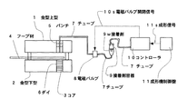
図1は本発明の成形機の構成図である。
図1において、1は金型上型、2は金型下型、3はコア、4はフープ材、5はパンチ、6はダイ、7はチューブ、8は電磁バルブ、9は接着剤容器、9wは接着剤、10はコントローラ、11は成形機制御盤、10sは電磁バルブ開閉信号、11sは成形信号である。
接着剤容器9中に接着剤9wを充填しており、コントローラ10からエアーがチューブ7を介して接着剤容器9に送られる。エアー圧力により接着剤9wがチューブ7を介して電磁バルブ8まで送られる。成形機の始動と同時に成形機制御盤11から成形信号11sがコントローラ10に送られ、電磁バルブ開閉信号10sが電磁バルブ8に送られる。電磁バルブ開閉信号10sが電磁バルブ8に送られることにより、電磁バルブ8が成形信号11sと同期してバルブの開閉を行う。バルブ開放時に接着剤9wがチューブ7を介して金型上型1まで送られ、金型上型1が金型下型2に近接する際に接着剤9wがフープ材4に塗布されると同時に接着剤9wが塗布されたフープ材(金属薄板)4は他のフープ材4から切り離され、積層し、コア3を形成する。
フープ材4から金属薄板が切り離される前に1カ所のかしめ突起(実施例2)またはそのかしめに代えてジャンピングカット(実施例3)が形成され、かつ接着剤が塗布された金属薄板はダイ6内で側面から一定圧力をかけることにより、かしめ接合と同時に接着剤硬化を促進させる。金型から放出されたコアは、かしめと接着剤により製造上十分な強度を持っている。
FIG. 1 is a block diagram of a molding machine according to the present invention.
In FIG. 1, 1 is a mold upper mold, 2 is a mold lower mold, 3 is a core, 4 is a hoop material, 5 is a punch, 6 is a die, 7 is a tube, 8 is an electromagnetic valve, 9 is an adhesive container, 9w is an adhesive, 10 is a controller, 11 is a molding machine control panel, 10s is an electromagnetic valve opening / closing signal, and 11s is a molding signal.
An adhesive 9 w is filled in the
Before the metal sheet is cut off from the
図2は外径切離し前のかしめを形成する薄板金属を製作する際の状態図である。17はフープ材、18はVパンチである。かしめを形成する薄板金属を製作する際は、Vパンチ18がフープ材17の厚みの1/3程度押すことにより、フープ材にへこみが生じる。
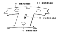
図3はかしめ構造を有した薄板金属の構成図である。30はかしめによる凸部、31、32、33は接着剤塗布箇所である。
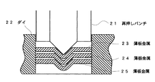
図4は外径切離し時のかしめを形成する薄板金属を製作する際の状態図である。21は再押しパンチ、22はダイ、23、24.25は薄板金属である。外径切離し前のかしめを図2の方法で形成された薄板金属は、最終的に外径を切り離す際にダイ22により、外径形状がフープ材から切り離され、再押しパンチ21がかしめ部を押すことにより、かしめを施した状態で金属薄板23,24,25が積層される。
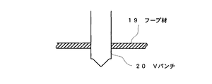
図5はジャンピングカットした金属薄板を成形する際の状態図である。19はフープ材、20はVパンチである。ジャンピングカットした金属薄板を成形する際、Vパンチ20がフープ材19より下がることにより、フープ材19に穴を開ける。
図6はジャンピングカットを有した薄板金属の斜視図である。26はジャンピングカット、27、28、29は接着剤塗布箇所である。
以上のように、実施例1に係る成形機の発明は、図3および図6で示す薄板金属に1箇所かしめによる凸部30およびジャンピングカット26を形成すると共に接着剤を複数箇所に塗布できるのが特徴である。
FIG. 2 is a state diagram at the time of manufacturing a sheet metal that forms a caulking before the outer diameter is cut off. 17 is a hoop material and 18 is a V punch. When a sheet metal that forms caulking is manufactured, the V punch 18 presses about 1/3 of the thickness of the hoop material 17, so that a dent is generated in the hoop material.
FIG. 3 is a configuration diagram of a thin metal plate having a caulking structure. 30 is a convex part by caulking, and 31, 32, and 33 are adhesive application locations.
FIG. 4 is a state diagram when a sheet metal forming a caulking when the outer diameter is cut off is produced. 21 is a re-pressing punch, 22 is a die, and 23 and 24.25 are thin metal plates. The thin plate metal formed by the method of FIG. 2 before severing the outer diameter is cut off from the hoop material by the die 22 when the outer diameter is finally cut, and the re-pressing punch 21 squeezes the caulked portion. By pushing, the
FIG. 5 is a state diagram when forming a jumping cut metal sheet. 19 is a hoop material, and 20 is a V punch. When forming a jumping-cut metal sheet, the V punch 20 is lowered from the hoop material 19 to make a hole in the hoop material 19.
FIG. 6 is a perspective view of a sheet metal having a jumping cut. 26 is a jumping cut, and 27, 28, and 29 are adhesive application locations.
As described above, the invention of the molding machine according to Example 1 can form the convex portion 30 and the jumping cut 26 by caulking at one place on the thin metal plate shown in FIGS. 3 and 6, and can apply the adhesive to plural places. Is a feature.
実施例2は、図3で示す薄板金属のみを積層してコアブロックを作るのが特徴である。図4の金属薄板24は実施例1の成形機によって図3に示すかしめによる凸部30が1箇所形成されかつ31〜33の3箇所に接着剤が塗布されている。この金属薄板24の凸部30がその上下に積層される金属薄板23,25の凸部30と互いに嵌合して各金属薄板23,24,25同士の位置決めがなされ、さらに積層された各金属薄板23,24,25同士は接着剤塗布箇所31,32,33によっても固着される。
このように、実施例2によれば、かしめと接着剤を併用し接合していることにより、積層状態を保持出来ないという危険性がなくなり、更にかしめ箇所を1箇所に限定していることにより、鉄損を抑えることが可能となる。
The second embodiment is characterized in that a core block is made by laminating only thin metal sheets shown in FIG. The metal
Thus, according to Example 2, there is no danger that the laminated state cannot be maintained by jointly using caulking and an adhesive, and further, the caulking location is limited to one location. It becomes possible to suppress iron loss.
実施例2のかしめ(1カ所)と接着によるコアブロックはこのように鉄損を抑えることが可能となったが、なお、若干の改良すべき点が判明した。以下、それについて説明する。
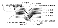
図7はかしめのみで形成されたコアのかしめ部分の拡大断面図である。
34、35、36、37はかしめを形成した薄板金属、38、39、40は隙間、41は薄板金属の厚みT1、42は半径R1、43は半径R2、44、45、46は隙間である。
実施例2のかしめによる積層方法では、かしめにより薄板金属34、35、36、37(図7)に、内径R1の窪み42と外径R2の突起43からなる突起が形成される。42の半径R1と43の半径R2の関係は、かしめによる突起部の厚み変化がほとんどないことから
半径R2=半径R1+T1(薄板金属の厚み)
がほぼ成り立つ。
半径R2の43は半径R1の42より大きいことから、薄板金属積層間には隙間44、45、46が生じ、隙間38、39、40が発生する。
このように、かしめのみで形成されたコアでは隙間38、39、40が発生し、巻線時にコアのかしめによる積層間強度が巻線張力に負け、コアの巻線箇所が圧縮されることにより巻線側に変形し、巻数が当初設定よりも減少するという問題があることが判った
The caulking (one place) and the core block by adhesion in Example 2 were able to suppress the iron loss in this way, but it was found that some points to be improved. This will be described below.
FIG. 7 is an enlarged cross-sectional view of a caulking portion of a core formed only by caulking.
34, 35, 36, and 37 are thin metal plates that have been crimped, 38, 39, and 40 are gaps, 41 is a thickness T1, 42 is a radius R1, 43 is a radius R2, 44, 45, and 46 are gaps. .
In the laminating method by caulking according to the second embodiment, the thin metal plates 34, 35, 36, and 37 (FIG. 7) are formed by caulking to form a protrusion 42 having a recess 42 having an inner diameter R1 and a protrusion 43 having an outer diameter R2. The relation between the radius R1 of 42 and the radius R2 of 43 is that there is almost no change in the thickness of the protrusion due to caulking.
Is almost true.
Since 43 of the radius R2 is larger than 42 of the radius R1, gaps 44, 45, 46 are generated between the thin metal laminates, and
In this way, in the core formed only by caulking,
実施例3は実施例2の克服すべき点を解消したものである。
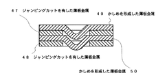
図8はジャンピングカットを有した薄板金属とかしめ構造を有した薄板金属を交互に積層形成されたコアの断面図である。47、48はジャンピングカットを有した薄板金属、49、50はかしめを形成した薄板金属である。
図7に対し、図8のジャンピングカットを有した薄板金属47、48が、かしめを形成した薄板金属49、50間に挿入されている積層方法では、かしめを有した薄板金属に近接する上下にかしめを有した薄板金属が無いため、突起間が干渉しなくなり積層間に隙間が発生しない。
このように、ジャンピングカットを有した薄板金属とかしめ構造を有した薄板金属を交互に積層形成されたコアではジャンピングカットを有した薄板金属47、48が、かしめを形成した薄板金属49、50間に挿入されていることより、かしめによる積層間の位置精度は保持したままで、積層間の隙間が従来と比較し狭くなり、密着性が向上し、巻線時にコアの巻線箇所が圧縮されることにより巻線側に変形する危険性がなくなった。
The third embodiment eliminates the problems to be overcome in the second embodiment.
FIG. 8 is a cross-sectional view of a core formed by alternately laminating thin plate metals having jumping cuts and thin plate metals having a caulking structure. 47 and 48 are thin metal plates having jumping cuts, and 49 and 50 are thin metal plates with caulking.
In contrast to FIG. 7, in the laminating method in which the thin metal plates 47 and 48 having the jumping cut shown in FIG. 8 are inserted between the thin metal members 49 and 50 having the caulking, the upper and lower portions are close to the thin metal having the caulking. Since there is no thin metal sheet with caulking, the projections do not interfere with each other and no gap is generated between the stacked layers.
In this way, in the core formed by alternately laminating the thin plate metal having the jumping cut and the thin plate metal having the caulking structure, the thin plate metals 47 and 48 having the jumping cut are arranged between the thin plate metals 49 and 50 having the crimp. As a result, the gap between the layers is reduced compared to the conventional method, while maintaining the positional accuracy between the layers by caulking. This eliminates the risk of deformation to the winding side.
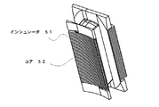
図9は巻線を行う前のコアの構成図である。51はインシュレータ、52はコアである。
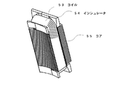
図10は巻線を行った後のコア構成図である。53はコイル、54はインシュレータ、55はコアである。
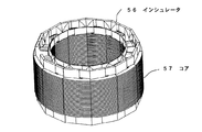
図11は巻線を行う前のコアをリング状に連結したステータコアの構成図である。56はインシュレータ、57はコアである。
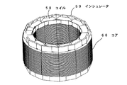
図12は巻線を行ったコアをリング状に連結したステータコアの構成図である。58はコイル、59はインシュレータ、60はコアである。
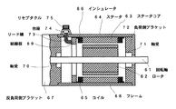
図13は電動機の側断面図である。
図において61は回転軸、62はロータ、63はステータコア、64はステータ、65はコイル、66はインシュレータ、67は反負荷側ブラケット、68はフレーム、69は結線板、70、71は軸受、72は反負荷側ブラケット、73はリード線、74は台座、75はリセプタクルとなっている。
このように、本発明に係るステータコア63を用いることで、巻線によるコアの変形を抑えることが可能になり、従来より多くの巻数の巻線が可能となり、電動機の特性が高められることとなる。
FIG. 9 is a configuration diagram of the core before winding. 51 is an insulator and 52 is a core.
FIG. 10 is a core configuration diagram after winding. 53 is a coil, 54 is an insulator, and 55 is a core.
FIG. 11 is a configuration diagram of a stator core in which the cores before winding are connected in a ring shape. 56 is an insulator, and 57 is a core.
FIG. 12 is a configuration diagram of a stator core in which wound cores are connected in a ring shape. 58 is a coil, 59 is an insulator, and 60 is a core.
FIG. 13 is a sectional side view of the electric motor.
In the figure, 61 is a rotating shaft, 62 is a rotor, 63 is a stator core, 64 is a stator, 65 is a coil, 66 is an insulator, 67 is an anti-load side bracket, 68 is a frame, 69 is a connection plate, 70 and 71 are bearings, 72 Is an anti-load side bracket, 73 is a lead wire, 74 is a pedestal, and 75 is a receptacle.
As described above, by using the stator core 63 according to the present invention, it becomes possible to suppress the deformation of the core due to the winding, and more windings than before can be achieved, and the characteristics of the electric motor can be improved. .
1 金型上型
2 金型下型
3 コア
4 フープ材
5 パンチ
6 ダイ
7 チューブ
8 電磁バルブ
9 接着剤容器
9w 接着剤
10 コントローラ
10s 電磁バルブ開閉信号
11 成形機制御盤
11s 成形信号である。
19、17 フープ材
20、18 Vパンチ
21 再押しパンチ
22 ダイ
23〜25 薄板金属
26 ジャンピングカット
27〜29、31〜33 接着剤塗布箇所
30 かしめによる凸部
34〜37 かしめを形成した薄板金属
38〜40、44〜46 隙間
41 薄板金属の厚みT1
42 半径R1
43 半径R2
47、48 ジャンピングカットを有した薄板金属
49、50 かしめを形成した薄板金属
51、54、56、59、66 インシュレータ
52 、55、57、60 コア
53、58、65 コイル
61 回転軸
62 ロータ
63 ステータコア
64 ステータ
67 反負荷側ブラケット
68 フレーム
69 結線板
70、71 軸受
72 負荷側ブラケット
73 リード線
74 台座
75 リセプタクル
DESCRIPTION OF
19, 17 Hoop material 20, 18 V punch 21 Re-press punch 22 Die 23-25 Thin plate metal 26 Jumping cut 27-29, 31-33 Adhesive application point 30 Convex part 34-37 by caulking Thin plate metal 38 with caulking formed -40, 44-46 Gap 41 Thickness T1 of sheet metal
42 radius R1
43 Radius R2
47, 48 Thin metal plate 49, 50 with jumping cut Thin metal plate 51, 54, 56, 59, 66 Insulator 52, 55, 57, 60 Core 53, 58, 65 Coil 61 Rotating shaft 62 Rotor 63 Stator core 64 Stator 67 Anti-load side bracket 68 Frame 69 Connection plate 70, 71 Bearing 72 Load side bracket 73 Lead wire 74 Base 75 Receptacle
Claims (6)
Priority Applications (1)
| Application Number | Priority Date | Filing Date | Title |
|---|---|---|---|
| JP2007239341A JP2009072014A (en) | 2007-09-14 | 2007-09-14 | Core block, core, stator for electric motor, and electric motor thereof |
Applications Claiming Priority (1)
| Application Number | Priority Date | Filing Date | Title |
|---|---|---|---|
| JP2007239341A JP2009072014A (en) | 2007-09-14 | 2007-09-14 | Core block, core, stator for electric motor, and electric motor thereof |
Publications (1)
| Publication Number | Publication Date |
|---|---|
| JP2009072014A true JP2009072014A (en) | 2009-04-02 |
Family
ID=40607686
Family Applications (1)
| Application Number | Title | Priority Date | Filing Date |
|---|---|---|---|
| JP2007239341A Pending JP2009072014A (en) | 2007-09-14 | 2007-09-14 | Core block, core, stator for electric motor, and electric motor thereof |
Country Status (1)
| Country | Link |
|---|---|
| JP (1) | JP2009072014A (en) |
Cited By (14)
| Publication number | Priority date | Publication date | Assignee | Title |
|---|---|---|---|---|
| JP2011087374A (en) * | 2009-10-14 | 2011-04-28 | Mitsubishi Electric Corp | Stacked fixed core for rotary electric machine |
| JP2013059262A (en) * | 2012-12-28 | 2013-03-28 | Mitsubishi Electric Corp | Stator core and stator and motor and compressor |
| CN103138426A (en) * | 2011-11-30 | 2013-06-05 | 丰田纺织株式会社 | Laminate of metal plates, core for rotating electrical machine, and laminating method for laminate of metal plates |
| JP2013236499A (en) * | 2012-05-10 | 2013-11-21 | Mitsubishi Electric Corp | Lamination iron core of electric motor |
| WO2016015869A1 (en) * | 2014-07-30 | 2016-02-04 | Kienle + Spiess Gmbh | Laminated core and method for producing same |
| JP2016025724A (en) * | 2014-07-18 | 2016-02-08 | トヨタ紡織株式会社 | Core of rotary electric machine |
| JP2017046480A (en) * | 2015-08-27 | 2017-03-02 | 日産自動車株式会社 | Manufacturing method of rotor core and rotor core of rotating electrical machine |
| US9876398B2 (en) | 2013-06-14 | 2018-01-23 | Honda Motor Co., Ltd. | Stator core for rotating electric machine |
| JP2020089202A (en) * | 2018-11-30 | 2020-06-04 | 三菱電機株式会社 | Laminated core, stator and rotor |
| JP2020092531A (en) * | 2018-12-06 | 2020-06-11 | 三菱電機株式会社 | Stator, rotating electric machine using stator, and method for manufacturing stator |
| JPWO2020262298A1 (en) * | 2019-06-26 | 2020-12-30 | ||
| CN112234733A (en) * | 2020-10-20 | 2021-01-15 | 苏州范斯特机械科技有限公司 | New motor core |
| KR20210147421A (en) * | 2020-05-28 | 2021-12-07 | 주진 | Laminated core having hybrid coupling means, and manufacturing method thereof |
| US20220219223A1 (en) * | 2019-05-27 | 2022-07-14 | Schaeffler Technologies AG & Co. KG | Punching and clinching of metal sheets |
-
2007
- 2007-09-14 JP JP2007239341A patent/JP2009072014A/en active Pending
Cited By (28)
| Publication number | Priority date | Publication date | Assignee | Title |
|---|---|---|---|---|
| JP2011087374A (en) * | 2009-10-14 | 2011-04-28 | Mitsubishi Electric Corp | Stacked fixed core for rotary electric machine |
| CN103138426A (en) * | 2011-11-30 | 2013-06-05 | 丰田纺织株式会社 | Laminate of metal plates, core for rotating electrical machine, and laminating method for laminate of metal plates |
| CN103138426B (en) * | 2011-11-30 | 2015-02-25 | 丰田纺织株式会社 | Laminate of metal plates, core for rotating electrical machine, and laminating method for laminate of metal plates |
| US9246360B2 (en) | 2011-11-30 | 2016-01-26 | Toyota Boshoku Kabushiki Kaisha | Laminate of metal plates, core for rotating electrical machine, and laminating method for laminate of metal plates |
| JP2013236499A (en) * | 2012-05-10 | 2013-11-21 | Mitsubishi Electric Corp | Lamination iron core of electric motor |
| JP2013059262A (en) * | 2012-12-28 | 2013-03-28 | Mitsubishi Electric Corp | Stator core and stator and motor and compressor |
| US9876398B2 (en) | 2013-06-14 | 2018-01-23 | Honda Motor Co., Ltd. | Stator core for rotating electric machine |
| JP2016025724A (en) * | 2014-07-18 | 2016-02-08 | トヨタ紡織株式会社 | Core of rotary electric machine |
| US10720802B2 (en) | 2014-07-30 | 2020-07-21 | Kienle + Spiess Gmbh | Laminated core and method for producing same |
| CN106716797A (en) * | 2014-07-30 | 2017-05-24 | 金勒+施皮斯有限公司 | Laminated core and method for producing same |
| JP2017521994A (en) * | 2014-07-30 | 2017-08-03 | キーンレ ウント シュピース ゲーエムベーハー | Laminated iron core and method for manufacturing the same |
| WO2016015869A1 (en) * | 2014-07-30 | 2016-02-04 | Kienle + Spiess Gmbh | Laminated core and method for producing same |
| JP2017046480A (en) * | 2015-08-27 | 2017-03-02 | 日産自動車株式会社 | Manufacturing method of rotor core and rotor core of rotating electrical machine |
| JP2020089202A (en) * | 2018-11-30 | 2020-06-04 | 三菱電機株式会社 | Laminated core, stator and rotor |
| JP2020092531A (en) * | 2018-12-06 | 2020-06-11 | 三菱電機株式会社 | Stator, rotating electric machine using stator, and method for manufacturing stator |
| JP7151438B2 (en) | 2018-12-06 | 2022-10-12 | 三菱電機株式会社 | Stator, rotary electric machine using this stator, and method for manufacturing stator |
| US20220219223A1 (en) * | 2019-05-27 | 2022-07-14 | Schaeffler Technologies AG & Co. KG | Punching and clinching of metal sheets |
| US11772149B2 (en) * | 2019-05-27 | 2023-10-03 | Schaeffler Technologies AG & Co. KG | Punching and clinching of metal sheets |
| CN114008891A (en) * | 2019-06-26 | 2022-02-01 | 日本制铁株式会社 | Core block, laminated core, and rotating electrical machine |
| WO2020262298A1 (en) * | 2019-06-26 | 2020-12-30 | 日本製鉄株式会社 | Core block, stacked core, and rotating electrical machine |
| JPWO2020262298A1 (en) * | 2019-06-26 | 2020-12-30 | ||
| EP3993224A4 (en) * | 2019-06-26 | 2023-04-05 | Nippon Steel Corporation | CORE BLOCK, STACKED CORE AND ROTATING ELECTRIC MACHINE |
| JP7299527B2 (en) | 2019-06-26 | 2023-06-28 | 日本製鉄株式会社 | CORE BLOCK, LAMINATED CORE, ROTATING ELECTRIC MACHINE, AND METHOD OF MANUFACTURING CORE BLOCK |
| CN114008891B (en) * | 2019-06-26 | 2024-10-15 | 日本制铁株式会社 | Core block, laminated core and rotating motor |
| US12126217B2 (en) | 2019-06-26 | 2024-10-22 | Nippon Steel Corporation | Core block, laminated core, and electric motor |
| KR20210147421A (en) * | 2020-05-28 | 2021-12-07 | 주진 | Laminated core having hybrid coupling means, and manufacturing method thereof |
| KR102395918B1 (en) * | 2020-05-28 | 2022-05-06 | 주진 | Laminated core having hybrid coupling means, and manufacturing method thereof |
| CN112234733A (en) * | 2020-10-20 | 2021-01-15 | 苏州范斯特机械科技有限公司 | New motor core |
Similar Documents
| Publication | Publication Date | Title |
|---|---|---|
| JP4819864B2 (en) | Method for manufacturing a stator and stator manufactured by the method | |
| CN109311073B (en) | Blanking method for metal parts and punching device suitable for the punching method | |
| KR101345029B1 (en) | Method of manufacturing molded stator of dynamo electric machine | |
| JP4938389B2 (en) | Laminated core and stator | |
| JP2003219585A (en) | Laminated core and method of manufacturing the same | |
| JPWO2010082465A1 (en) | Manufacturing method of laminated core and manufacturing jig thereof | |
| JP2017017855A (en) | Manufacturing method for laminated core | |
| JP2016123976A (en) | Punching method for laminated iron core and method for producing laminated iron core | |
| JP2006353001A (en) | Laminated iron core and method and apparatus for manufacturing the same | |
| JP7062921B2 (en) | Manufacturing method of stator core | |
| JP5991241B2 (en) | Core manufacturing method | |
| JP2011223844A (en) | Laminating iron core and manufacturing method thereof | |
| JP3294638B2 (en) | Method of manufacturing stator core for electric motor | |
| CN106716797A (en) | Laminated core and method for producing same | |
| JP3313965B2 (en) | Manufacturing method of laminated iron core using amorphous alloy foil strip | |
| JP6509373B2 (en) | Core sheet, divided laminated core and stator, and method of manufacturing divided laminated core | |
| JP6438731B2 (en) | Punching method, punching apparatus, and method for manufacturing laminated iron core | |
| JP2016092949A (en) | Punching method | |
| JP2006158066A (en) | LAMINATED CORE, ITS MANUFACTURING METHOD, AND DIE DEVICE | |
| JP3660532B2 (en) | Electric motor and method for manufacturing electric motor core | |
| JP2006101629A (en) | Manufacturing method of laminated core | |
| JP6392089B2 (en) | Punching method, punching apparatus, and method for manufacturing laminated iron core | |
| JP7137918B2 (en) | Laminated core manufacturing method | |
| JPH04117153A (en) | Manufacture of laminated core | |
| JP3842146B2 (en) | Manufacturing method of laminated iron core |