JP2009078024A - Hot air / air blowing unit - Google Patents
Hot air / air blowing unit Download PDFInfo
- Publication number
- JP2009078024A JP2009078024A JP2007250390A JP2007250390A JP2009078024A JP 2009078024 A JP2009078024 A JP 2009078024A JP 2007250390 A JP2007250390 A JP 2007250390A JP 2007250390 A JP2007250390 A JP 2007250390A JP 2009078024 A JP2009078024 A JP 2009078024A
- Authority
- JP
- Japan
- Prior art keywords
- air
- main body
- suction
- futon
- blowing unit
- Prior art date
- Legal status (The legal status is an assumption and is not a legal conclusion. Google has not performed a legal analysis and makes no representation as to the accuracy of the status listed.)
- Withdrawn
Links
Images

Landscapes
- Mattresses And Other Support Structures For Chairs And Beds (AREA)
- Duct Arrangements (AREA)
Abstract
【課題】取り扱いが便利で、吸込口から使用者に聞こえる動作音を小さくできる温風・送風ユニットを提供する。
【解決手段】本体8に空気13を吸込む本体吸込み口と空気13を吹出す吹出し口を有し、本体8内に本体吸込み口から空気を吸込み前記吹出し口へ送風する送風ファンと、送風ファンを駆動するモータと、送風ファンから送風された空気13を加熱するヒータとを備え、吹出し口と空調布団1の内部に設けた収納袋とを連結管21で接続してなる温風・送風ユニットにおいて、本体吸込み口に伸縮自在で可撓性のある蛇腹構造の吸込み管11を接続し、吸込み管11は本体8に形成された収納空間に取り出し自在に収納できるようにした。
【選択図】図1The present invention provides a warm air / air blowing unit that is easy to handle and can reduce an operation sound heard by a user from a suction port.
A main body has a main body suction port for sucking air and a blowout port for blowing out air, and a blower fan that sucks air into the main body from the main body suction port and blows air to the blowout port. In a hot air / air blowing unit comprising a motor for driving and a heater for heating the air 13 blown from the blower fan, and connecting the outlet and the storage bag provided inside the air-conditioning futon 1 with a connecting pipe 21 The suction pipe 11 having a flexible bellows structure that can be expanded and contracted is connected to the main body suction port so that the suction pipe 11 can be taken out and stored in a storage space formed in the main body 8.
[Selection] Figure 1
Description
本発明は、空調布団に温風や常温の空気を送る温風・送風ユニットに関するものである。 The present invention relates to a warm air / air blowing unit that sends warm air or room temperature air to an air-conditioning futon.
人は、1日の中で約6時間を布団の中で睡眠を取っており、その睡眠をいかに充実させるかはとても大切なことである。しかし、日本の気候には四季があり、季節によって布団の中は様々な影響を受ける。 People sleep about 6 hours a day in a futon, and how to enhance that sleep is very important. However, there are four seasons in the Japanese climate, and the futon is affected in various ways depending on the season.
冬場は気温(室温)が低く、布団の中も冷たく、就寝しても体感的に寒く、足の指先などが温まるまでなかなか寝付けないものである。一方、夏場は気温(室温)や湿度が高く、布団の中も熱く、就寝中の発汗も伴い体感的に蒸し暑くなる。 In winter, the temperature (room temperature) is low, the futon is cold, it feels cold even when you go to bed, and it is difficult to sleep until the toes of your feet are warm. On the other hand, in summer, the temperature (room temperature) and humidity are high, the futon is hot, and sweating during sleep is also sultry.
以上のように布団の中は、季節によって温度が変化し、特に冬場と夏場は良好な睡眠環境を得るのが難しい状況にあった。 As described above, the temperature in the futon varied depending on the season, and it was difficult to obtain a good sleep environment especially in winter and summer.
良好な睡眠環境を得るための対策として、ルームエアコンや扇風機、或いは暖房器具等の空調用機器を使用して、就寝する室内の環境を管理することが一般に行われている。 As a measure for obtaining a good sleep environment, it is generally performed to manage the environment of a sleeping room by using an air conditioner such as a room air conditioner, a fan, or a heater.
近年では、布団本体で快適な睡眠環境を得るために、布団の内部を空調管理するものが提供されている。 In recent years, in order to obtain a comfortable sleeping environment in the futon body, there is provided an air-conditioning management unit for the inside of the futon.
それは、布団と温風・送風ユニットを組み合わせたもので、冬場は布団の内部に温風を送り布団を暖かくするもので、夏場は布団の内部に室内空気を送風し、使用者の発汗による湿度や熱気を布団の外に放出する機能を備えたものである。 It is a combination of a futon and a warm air / air blowing unit. In winter, warm air is sent to the inside of the futon to warm the futon, and in summer, indoor air is blown into the inside of the futon and the humidity caused by user sweating. It has the function of releasing hot air and futon outside.
この布団は、空調布団と言われるもので、その構成は、通気性のあるカバー内に、通気性のある収納袋を設け、収納袋に温風や送風を供給する温風・送風ユニットを接続したものである。 This futon is said to be an air-conditioning futon, and its structure is that a breathable storage bag is provided in a breathable cover, and a hot air / air blowing unit that supplies warm air and air to the storage bag is connected. It is what.
また、温風・送風ユニットは、本体内にモータと送風ファン及びヒータ等を内蔵し、モータで送風ファンを駆動し、送風ファンの回転により本体内に空気を吸込み、吸込んだ空気をヒータで加熱等して布団の中の収納袋に送り、布団を暖め、また、布団の内部の熱気や湿度を取り除くものである。 In addition, the hot air / air blow unit has a motor, a blower fan, a heater, and the like built in the main body, the fan is driven by the motor, air is sucked into the main body by the rotation of the blower fan, and the sucked air is heated by the heater. Etc., and sent to the storage bag in the futon to warm the futon and remove the hot air and humidity inside the futon.
この温風・送風ユニットは、上記したように本体内にモータと送風ファンを内蔵し、就寝時に動作させるので、モータと送風ファンの動作音は温風・送風ユニットの吸込み口から室内に放出される。従って就寝時の動作音は使用者にとって小さいほど望ましい。 As described above, this hot air / air blowing unit has a motor and an air blowing fan built in the main body and is operated at bedtime. Therefore, the operation sound of the motor and the air blowing fan is released into the room through the air intake of the hot air / air blowing unit. The Therefore, it is desirable that the operation sound at bedtime is as small as possible for the user.
この動作音の対策として、一般的には本体の側面等に例えば格子状の吸込み口を設け、該吸込み口にスポンジ状の消音材等を被せ、この消音材を通して本体の内部に室内空気を吸込むようにしている。 As a countermeasure against this operating noise, for example, a suction port in the form of a grid is generally provided on the side of the main body, and a sponge-like silencer is put on the suction port, and indoor air is sucked into the main body through the silencer. I am trying.
また、特許文献1の図1に示すように、温風・送風ユニットの吸込み口から放出される音が使用者の近くで発しないように、外部送風装置(温風・送風ユニット)に吸込み管を接続し、該吸込み管の先端吸込み口を使用者から遠いところに開口させるようにしたものも提案されている。
Further, as shown in FIG. 1 of
上記従来技術において、本体の側面等に例えば格子状の吸込み口を設け、該吸込み口に消音材等を設けたものでは、消音材等により本体内への空気の吸込みが阻害され、温風・送風ユニットとしての性能が劣化するため、消音材に十分な消音効果を持たせることが難しく、使用者が気にならないほど動作音を消すことは難しい。 In the above prior art, for example, a lattice-shaped suction port is provided on the side surface of the main body, and the suction port is provided with a sound deadening material or the like. Since the performance as the blower unit is deteriorated, it is difficult to give the sound-absorbing material a sufficient sound-deadening effect, and it is difficult to turn off the operation sound so that the user does not care.
また、特許文献1に示すように、外部送風装置(温風・送風ユニット)に空気吸込み管が突き出るように接続したものは、前記したものより動作音が気にならなくなるが、外部送風装置(温風・送風ユニット)の移動時や、収納時に空気吸込み管が邪魔になり、大変使い勝手が悪いという欠点がある。
In addition, as shown in
本発明の目的は、取り扱いが便利で、吸込み口から使用者に聞こえる動作音を小さくできる温風・送風ユニットを提供することにある。 An object of the present invention is to provide a warm air / air blowing unit that is easy to handle and can reduce the operation sound that can be heard by a user through a suction port.
本発明は上記の問題を解決するためになされたものであり、請求項1では、本体に空気を吸込む本体吸込み口と空気を吹出す吹出し口を有し、前記本体内に前記本体吸込み口から空気を吸込み前記吹出し口へ送風する送風ファンと、該送風ファンを駆動するモータと、前記送風ファンから送風された空気を加熱するヒータとを備え、前記吹出し口と空調布団の内部に設けた収納袋とを連結管で接続してなる温風・送風ユニットにおいて、前記本体吸込み口に伸縮自在で可撓性のある蛇腹構造の吸込み管を接続し、該吸込み管は前記本体に成形された収納空間に取り出し自在に収納するものである。
The present invention has been made in order to solve the above-mentioned problem. In
請求項2では、前記吸込み管の空気吸込み側の先端部に、空気の吸込み口を前記吸込み管の周方向に向けた吸気管を有し、該吸気管の吸込み口は、前記吸込み管の周方向に対して任意の方向に回転できるようにしたものである。 According to a second aspect of the present invention, an air intake pipe having an air intake port directed in a circumferential direction of the intake pipe is provided at a distal end portion of the air intake side of the intake pipe, and the intake port of the intake pipe is arranged around the periphery of the intake pipe. It can be rotated in any direction with respect to the direction.
本発明の請求項1によれば、本体内に空気を吸込む吸込み口から使用者に聞こえる動作音を小さくできる温風・送風ユニットを提供することができる。
According to
また、吸込み管を温風・送風ユニット本体の収納空間に収納できるので、温風・送風ユニットの移動時や、収納時に関して取り扱いが大変便利になる。 Further, since the suction pipe can be stored in the storage space of the hot air / air blowing unit main body, the handling becomes very convenient when the hot air / air blowing unit is moved or stored.
請求項2によれば、吸込み管を使用者から遠ざけた後、吸込み口を任意の方向に曲げて使用できるので、吸込み口を使用者の寝ている方向とは反対側に向けることが容易であり、さらに吸込み口からの動作音を小さくすることができる。
According to
以下、本発明の実施形態を図面を用いて説明する。 Hereinafter, embodiments of the present invention will be described with reference to the drawings.
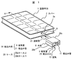
図1は、空調布団に温風・送風ユニット本体を接続した実施例を示す。 FIG. 1 shows an embodiment in which a hot air / blower unit body is connected to an air-conditioning futon.
空調布団1は、内部に後述する収納袋5を備え、収納袋5に設けられた挿入口6を介して後述する温風・送風ユニット本体8から温風や空気の供給を受ける。挿入口6は通気性のよいカバー2の開口2aから外部に臨ませている。
The air-
温風・送風ユニット本体8は、ケース上30aとケース下30bとで外郭を構成し、外郭の略対向した位置には、室内の空気13を吸込む吸込み部14と、吸込んだ空気を空調布団1に送るための連結管21が接続され、連結管21の先端は収納袋5の挿入口6に接続されている。
The hot air / air blow unit
また、温風・送風ユニット本体8は、内蔵する後述のモータ27で送風ファン15を駆動することにより、吸込み部14の先端の吸込み口24から空気を吸込み、吸込んだ空気を連結管21を介して空調布団1に送る。
Further, the hot air / air blowing unit
使用者は好みに応じて送風する空気を後述するヒータ17で加熱することができる。例えば、冬場の寒い時期には空調布団1に温風を供給し、空調布団1と、空調布団1の上に掛ける毛布や掛け布団(いずれも図示せず)等を暖め、快適に就寝することができる。また、夏場の暑い時期には空調布団1に室内の空気を送風し、就寝中の発汗による布団内の湿気や熱気を布団外に放出させ快適に就寝できるものである。
The user can heat the air to be blown with a heater 17 described later according to his / her preference. For example, in the cold season of winter, warm air can be supplied to the air-
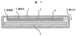
次に空調布団1について図7(図1のA−A断面矢視図)を用いて詳細に説明する。
Next, the air-
空調布団1は、袋状に構成された通気性のあるカバー2と、カバー2の内部に収納されたマットレス3と、このマットレス3の上に載せられた収納袋5とで構成されている。
The air-
マットレス3は、ウレタン等の材料を用い適度な堅さを持つものである。 The mattress 3 has moderate hardness using a material such as urethane.
収納袋5は、一端に挿入口6を有し、内部に立体格子空間材4を収納している。立体格子空間材4は、プラスチック製の糸を多数編み込みされており、これにより連通した空気層が形成され空気が流通することができる通気性を有し、この上に使用者が就寝しても、つぶれて空気層が無くなることがない程度の強度を有している。
The storage bag 5 has an
収納袋5は、下面及び側面が非通気または通気しにくい生地等で作られ、上面の一部、例えば使用者の頭部や足部に対応する部分または全面に通気孔7が設けられ、一部に外部から温風や空気の供給を受けるための挿入口6が設けられている。
The storage bag 5 is made of a fabric or the like whose bottom and side surfaces are not ventilated or difficult to ventilate, and a ventilation hole 7 is provided in a part of the top surface, for example, a part corresponding to the user's head or foot, or the entire surface. An
前記挿入口6の取付け位置や数は、空調布団1の内部の構成により異なる。例えば、使用者の足部側と頭部側の2ヶ所に収納袋5を備え、各収納袋5に挿入口6を設けることで、季節により二つの収納袋5を使い分け、頭寒足熱の空調を可能にすることができる。
The mounting position and number of the
すなわち、冬場の寒い時は足部側の収納袋に温風を送り、夏場の熱い時は頭部側の収納袋に室内の空気を送る使い方が可能となり、一年を通して温風・送風ユニットを使用することができる。また、設置場所の自由度を高めるために、空調布団1の左右や足部側に複数箇所の挿入口6を設け、温風・送風ユニット本体8の置く場所の自由度を確保すれば、使い勝手を良くすることができる。
In other words, it is possible to send warm air to the storage bag on the foot side when it is cold in the winter, and to send indoor air to the storage bag on the head side when it is hot in the summer. Can be used. In addition, in order to increase the degree of freedom of the installation place, a plurality of
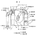
図2は、吸込み部14を縮めて温風・送風ユニット本体8の収納空間8aに収納し、ケース上30aを取り外して内部構造を示した説明図である。
FIG. 2 is an explanatory view showing the internal structure by contracting the
温風・送風ユニットの本体8の主な構成は、吸込み部14,収納空間8a,送風ファン15,モータ27,ヒータユニット18および連結管21である。
The main structure of the
吸込み部14は、温風・送風ユニット本体8の外部から空気13を吸込むためのもので、吸込み管11の先端に吸気管9を設け、基端を温風・送風ユニット本体8の本体吸込み口29に接続している。
The
吸気管9は、空気の吸込み方向を変えるもので、吸込み口24の方向を吸込み管11の周方向に向け、かつ、周方向のどの方向にも任意に回転できる構造になっている。
The
吸込み管11は、伸縮自在で可撓性のある蛇腹構造をなし、伸ばした状態,縮めた状態および曲げた状態で維持可能であり、強度は布団が載った程度では、つぶれずに吸気路が確保できる堅牢性を備えている。
The
吸込み部14は以上の構成によるもので、吸込み管11を縮め温風・送風ユニット本体8の収納空間8aに収納が可能となる。収納空間8aは、温風・送風ユニット本体8の本体吸込み口29の近傍に隔壁8b等によって形成されており、吸込み管11を縮めて曲げた状態で収納可能である。
The
送風ファン15は、ターボファンを使用し、吸込み口24,本体吸込み口29からファン吸気口28へと空気13を吸込み、後述するヒータユニット18に向けて送風する。このターボファンは、後述するモータ27の回転軸に取り付けられ、モータ27の駆動により回転をする。
The blower fan 15 uses a turbo fan, sucks
モータ27は、使用者が設定した温風・送風ユニット本体8の運転条件に対応するべく動作する。モータ27の運転条件とは、空調布団1へ供給する風量である。
The motor 27 operates to correspond to the operating conditions of the hot air / air
ヒータユニット18は、内部にヒータ17を有し、通過する空気を運転条件に応じて加熱する。このヒータ17は、ニクロム線ヒータやシーズヒータ等の使用も可能であるが、半導体ヒータが好適である。その理由は、自己温度制御機能を持った定温発熱体なので安全面などの理由からである。 The heater unit 18 has a heater 17 inside, and heats the passing air according to operating conditions. The heater 17 can be a nichrome wire heater or a sheathed heater, but a semiconductor heater is preferable. The reason is because it is a constant temperature heating element with a self-temperature control function, for safety reasons.
温度検出素子19は、ヒータ17と吹出し口16との間の風路内に設置し、ヒータ17を通過した空気の温度を検出するものである。
The
連結管21は、吸込み管11と同様に伸縮自在で可撓性のある蛇腹構造をなし、一端を吹出し口16に接続し、他端を空調布団1の挿入口6に接続し、温風・送風ユニット本体8から空調布団1へ温風や室内の空気を送るものである。
The connecting
制御部26は、温風・送風ユニット本体8内のヒータ17からの熱の影響を受けない位置に設置され、使用者が希望する温度や風量の運転条件をコントローラ(図示せず)の設定ボタン等で指定入力すると、その指定入力された運転条件に合わせてヒータ17の温度やモータ27の風量等を制御する。
The
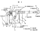
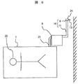
図3は、図2の温風・送風ユニット本体8の収納空間8aから吸込み部14を取り出し、吸込み管11を引き伸ばして、吸気管9の吸込み口24を使用者から遠い位置に開口させた状態の説明図である。
FIG. 3 shows a state in which the
図4は、温風・送風ユニット本体8の本体吸込み口29に、支点12を介して回転自在に接続管10を接続し、接続管10の他端に吸込み管11を接続した他の実施例の説明図である。この実施例によれば、接続管10及び吸込み管11が支点12を中心に可動するので、吸込み部14を収納空間8aに収納するのが容易となる。また、吸込み部14を温風・送風ユニット本体8に収納した状態から任意の角度に引出したり、任意の長さに伸ばして使用することが可能である。
FIG. 4 shows another embodiment in which the connecting pipe 10 is connected to the main
次に、上記の構成による動作を説明する。 Next, the operation according to the above configuration will be described.
上記したように、冬場は気温(室温)が低く、布団の中も冷たく、就寝しても体感的に寒く、足の指先などが温まるまでなかなか寝付けない。一方、夏場は気温(室温)や湿度が高く、布団の中も熱く、就寝中の発汗も伴い体感的に蒸し暑くなる。 As mentioned above, in winter, the temperature (room temperature) is low, the futon is cold, and even when you go to bed, it feels cold and you won't fall asleep until your toes get warm. On the other hand, in summer, the temperature (room temperature) and humidity are high, the futon is hot, and sweating during sleep is also sultry.
使用者は、気温(室温)の低い冬場か、気温や湿度の高い夏場かによって空調布団1内に温風を送るか、室内空気を入れるかの運転条件をコントローラ(図示せず)の設定ボタン等で使い分ける。
The user can set the operating condition of the controller (not shown) according to the operating condition of whether to send warm air into the air-
一例として、冬場に温風・送風ユニット本体8から空調布団1内に温風を送る動作について説明する。
As an example, an operation of sending warm air from the warm air / air
まず、図3に示すように、温風・送風ユニット本体8の連結管21の先端を空調布団1に収納されている収納袋5の挿入口6に接続し、吸込み部14を収納空間8aから取り出して吸込み管11を伸ばし、先端の吸込み口24を使用者の特に耳から遠い位置に設置する。
First, as shown in FIG. 3, the tip of the connecting
次に、コントローラの設定ボタン等により運転条件を入力すると、その指定入力された運転条件に合わせてヒータ17に通電されるとともに、モータ27が駆動して送風ファン15を回転する。前記ヒータ17の温度や送風ファン15の風量等は室温等を考慮して前記コントローラによって使用者の好みの状態に設定される。 Next, when an operating condition is input using a setting button or the like of the controller, the heater 17 is energized in accordance with the specified input operating condition, and the motor 27 is driven to rotate the blower fan 15. The temperature of the heater 17 and the air volume of the blower fan 15 are set to the user's favorite state by the controller in consideration of room temperature and the like.
前記送風ファン15の回転によって、吸込み管11の先端に接続された吸気管9から温風・送風ユニット本体8内に吸込まれた空気13は、送風ファン15の出口からヒータユニット18のヒータ17を通る間に加熱され、温風となって温風・送風ユニット本体8の吹出し口16から連結管21を通り、収納袋5の挿入口6から収納袋5内に流入する。そして、収納袋5の上面の通気孔7から空調布団1およびその上面に掛けられた毛布や掛け布団等を暖める。これによって、使用者は快適な睡眠をとることができる。なお、前記温風の温度は温度検知素子19によって設定された温度以上に上がらないように制御される。冬場の寒い時には、温風・送風ユニット本体8は以上のようにして使用される。
The
一方、夏場の気温や湿度の高いときには、コントローラによってヒータユニット18に通電しないようにし、温風・送風ユニット本体8を通して室内の空気を空調布団1に送り、布団の内部の湿度や熱気を布団の外に放出する。これによって、使用者は快適な睡眠をとることができる。なお、温風・送風ユニット本体8から空調布団1への室内の空気の送風は、上記冬場の場合と同じであり、説明を省略する。
On the other hand, when the temperature and humidity in summer are high, the controller prevents the heater unit 18 from being energized, sends the indoor air to the air-
次に、温風・送風ユニット本体8に接続される吸込み部14の使用方法について図5,図6を用いて説明する。
Next, the usage method of the
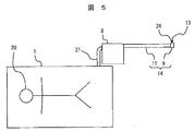
図5は、温風・温風ユニット本体8の収納空間8aから吸込み部14を取り出し、吸込み管11を伸ばして使用している説明図である。
FIG. 5 is an explanatory view in which the
温風・送風ユニット本体8の収納空間8aから吸込み部14を取り出し、吸込み管11を伸ばすことで、使用者20から温風・送風ユニット本体8の吸込み口24を遠ざけることができる。また、吸気管9の吸込み口24を使用者20と反対方向に向けることで、温風・送風ユニット本体8内に空気を吸込む吸込み口24から使用者20に聞こえる動作音を小さくすることができ、使用者は快適に睡眠をとることができる。
By removing the
すなわち、温風・送風ユニット本体8内への空気13の流れに沿って風路が形成され、その風路を伝ってモータ27や送風ファン15の動作音が吸込み口24から聞こえるが、使用者20までの音の伝播距離を長くできるようにしたことで、音の減衰量が大きくなり、使用者20に聞こえる動作音を小さくすることができる。
That is, an air passage is formed along the flow of the
次に、図6は、温風・温風ユニット本体8から伸ばした吸込み部14を曲げて使用している状態の説明図である。
Next, FIG. 6 is an explanatory diagram of a state where the
温風・温風ユニット本体8を使用する部屋の環境により、部屋の大きさや家具などの配置によって吸込み管11を直線的に配置できない時は、吸込み管11を曲げて使用する。
If the
温風・送風ユニット本体8から吸込み部14を取り出し、吸込み管11を伸ばして曲げることで、温風・送風ユニット本体8の吸込み口24を使用者20から遠ざけることができる。また、吸気管9の吸込み口24は使用者20と反対方向に向けることができる。さらに、吸気管9を吸込み管11の周方向のどの方向にも任意に向けられるようにすることで、温風・送風ユニット本体8を使用する部屋の環境に合わせて吸気管9の向きを適宜調整して使用者20に聞こえる動作音を小さくすることができる。
The
また、このとき、図4に示すように、温風・送風ユニット本体8の本体吸込み口29に、支点12を介して回転自在に接続管10を接続し、接続管10の他端に吸込み管11を接続すれば、吸込み管11が支点12を中心に可動するので、任意の角度に曲げたり,伸ばしたりする作業が容易である。
At this time, as shown in FIG. 4, the connecting pipe 10 is connected to the main
一方、温風・送風ユニット本体8を使用しない時には、連結管21を空調布団1から取り外し、さらに吸込み部14の吸込み管11の蛇腹部を縮めて収納空間8a内に収納する。
On the other hand, when the hot air / air blowing unit
このように、吸込み部14を温風・送風ユニット本体8内に収納ができるので、温風・送風ユニット本体8の移動時や、収納時に関して取り扱いが大変便利になる。
Thus, since the
以上説明したように、本発明によれば、温風・送風ユニット本体8内に空気を吸込む吸込み口24から使用者に聞こえる動作音を小さくできる温風・送風ユニットを提供することができる。
As described above, according to the present invention, it is possible to provide a warm air / air blowing unit that can reduce the operating sound heard by the user from the
また、吸込み部14の吸込み管11を温風・送風ユニット本体8の収納空間8aに収納できるので、温風・送風ユニットの移動時や、収納時に関して取り扱いが大変便利になる。
Further, since the
さらに、吸込み管11を使用者から遠ざけた後、吸込み口24を任意の方向に曲げて使用できるので、吸込み口24を使用者の寝ている方向とは反対側に向けることが容易であり、さらに吸込み口から聞こえる動作音を小さくすることができる。
Furthermore, after the
1 空調布団
5 収納袋
6 挿入口
8 本体
8a 収納空間
9 吸気管
10 接続管
11 吸込み管
14 吸込み部
15 送風ファン
16 吹出し口
17 ヒータ
21 連結管
27 モータ
29 本体吸込み口
DESCRIPTION OF
Claims (2)
前記本体吸込み口に伸縮自在で可撓性のある蛇腹構造の吸込み管を接続し、該吸込み管は前記本体に形成された収納空間に取り出し自在に収納することを特徴とする温風・送風ユニット。 A main body suction port that sucks air into the main body and a blowout port that blows air; a blower fan that sucks air into the main body from the main body suction port and blows air to the blowout port; and a motor that drives the blower fan; A heater for heating the air blown from the blower fan, and a hot air / blower unit formed by connecting the outlet and a storage bag provided inside the air-conditioning futon with a connecting pipe;
A hot air / blower unit characterized in that a flexible and bellows structure suction pipe is connected to the main body suction port, and the suction pipe is detachably stored in a storage space formed in the main body. .
Priority Applications (1)
| Application Number | Priority Date | Filing Date | Title |
|---|---|---|---|
| JP2007250390A JP2009078024A (en) | 2007-09-27 | 2007-09-27 | Hot air / air blowing unit |
Applications Claiming Priority (1)
| Application Number | Priority Date | Filing Date | Title |
|---|---|---|---|
| JP2007250390A JP2009078024A (en) | 2007-09-27 | 2007-09-27 | Hot air / air blowing unit |
Publications (1)
| Publication Number | Publication Date |
|---|---|
| JP2009078024A true JP2009078024A (en) | 2009-04-16 |
Family
ID=40653223
Family Applications (1)
| Application Number | Title | Priority Date | Filing Date |
|---|---|---|---|
| JP2007250390A Withdrawn JP2009078024A (en) | 2007-09-27 | 2007-09-27 | Hot air / air blowing unit |
Country Status (1)
| Country | Link |
|---|---|
| JP (1) | JP2009078024A (en) |
-
2007
- 2007-09-27 JP JP2007250390A patent/JP2009078024A/en not_active Withdrawn
Similar Documents
| Publication | Publication Date | Title |
|---|---|---|
| AU2001237887B2 (en) | A bed | |
| JP2013528776A (en) | System and method for thermoelectric personal comfort control bedding | |
| US20080028536A1 (en) | Mattress with cooling airflow | |
| AU2001237887A1 (en) | A bed | |
| US20150272338A1 (en) | Bed apparatus | |
| KR100826793B1 (en) | Hot and Cold Bed with Heat Transfer | |
| KR20090108518A (en) | Hot water boiler air mattress with cold air, natural air blowing and heat function | |
| JP2017086391A (en) | Multifunctional bedding | |
| KR200422541Y1 (en) | Air mattress with hot air, cold air, natural air blowing function and heat function | |
| KR200418715Y1 (en) | Air Conditioning Ventilated Duvet | |
| JP2006043333A (en) | Bed equipment | |
| KR200413011Y1 (en) | Mattress with hot / cold function | |
| KR101941913B1 (en) | Ventilating mattress | |
| JP2005204852A (en) | Thermotherapy device | |
| JP2005204853A (en) | Thermotherapy device | |
| JP2011041725A (en) | Bedding device | |
| JP2005006902A (en) | Pillow | |
| JP2005192883A (en) | Thermotherapy device | |
| JP4207680B2 (en) | bedding | |
| JP3033543U (en) | Residential air supply equipment | |
| WO2004074747A1 (en) | Radiation panel structure and air conditioner | |
| JP2005334087A (en) | Air controlled bedding and air controlled bedding set | |
| JP2009201977A (en) | Ecological sleep-bedding apparatus | |
| KR20190061599A (en) | Fan for ventilating mattress | |
| JP2005168621A (en) | Air controlled bedding |
Legal Events
| Date | Code | Title | Description |
|---|---|---|---|
| A300 | Withdrawal of application because of no request for examination |
Free format text: JAPANESE INTERMEDIATE CODE: A300 Effective date: 20101207 |