JP2009083594A - Control device for vehicle power transmission device - Google Patents
Control device for vehicle power transmission device Download PDFInfo
- Publication number
- JP2009083594A JP2009083594A JP2007254061A JP2007254061A JP2009083594A JP 2009083594 A JP2009083594 A JP 2009083594A JP 2007254061 A JP2007254061 A JP 2007254061A JP 2007254061 A JP2007254061 A JP 2007254061A JP 2009083594 A JP2009083594 A JP 2009083594A
- Authority
- JP
- Japan
- Prior art keywords
- power transmission
- control
- electric motor
- engine
- transmission device
- Prior art date
- Legal status (The legal status is an assumption and is not a legal conclusion. Google has not performed a legal analysis and makes no representation as to the accuracy of the status listed.)
- Pending
Links
Images




Classifications
-
- B—PERFORMING OPERATIONS; TRANSPORTING
- B60—VEHICLES IN GENERAL
- B60W—CONJOINT CONTROL OF VEHICLE SUB-UNITS OF DIFFERENT TYPE OR DIFFERENT FUNCTION; CONTROL SYSTEMS SPECIALLY ADAPTED FOR HYBRID VEHICLES; ROAD VEHICLE DRIVE CONTROL SYSTEMS FOR PURPOSES NOT RELATED TO THE CONTROL OF A PARTICULAR SUB-UNIT
- B60W10/00—Conjoint control of vehicle sub-units of different type or different function
- B60W10/04—Conjoint control of vehicle sub-units of different type or different function including control of propulsion units
- B60W10/08—Conjoint control of vehicle sub-units of different type or different function including control of propulsion units including control of electric propulsion units, e.g. motors or generators
-
- B—PERFORMING OPERATIONS; TRANSPORTING
- B60—VEHICLES IN GENERAL
- B60K—ARRANGEMENT OR MOUNTING OF PROPULSION UNITS OR OF TRANSMISSIONS IN VEHICLES; ARRANGEMENT OR MOUNTING OF PLURAL DIVERSE PRIME-MOVERS IN VEHICLES; AUXILIARY DRIVES FOR VEHICLES; INSTRUMENTATION OR DASHBOARDS FOR VEHICLES; ARRANGEMENTS IN CONNECTION WITH COOLING, AIR INTAKE, GAS EXHAUST OR FUEL SUPPLY OF PROPULSION UNITS IN VEHICLES
- B60K6/00—Arrangement or mounting of plural diverse prime-movers for mutual or common propulsion, e.g. hybrid propulsion systems comprising electric motors and internal combustion engines
- B60K6/20—Arrangement or mounting of plural diverse prime-movers for mutual or common propulsion, e.g. hybrid propulsion systems comprising electric motors and internal combustion engines the prime-movers consisting of electric motors and internal combustion engines, e.g. HEVs
- B60K6/22—Arrangement or mounting of plural diverse prime-movers for mutual or common propulsion, e.g. hybrid propulsion systems comprising electric motors and internal combustion engines the prime-movers consisting of electric motors and internal combustion engines, e.g. HEVs characterised by apparatus, components or means specially adapted for HEVs
- B60K6/36—Arrangement or mounting of plural diverse prime-movers for mutual or common propulsion, e.g. hybrid propulsion systems comprising electric motors and internal combustion engines the prime-movers consisting of electric motors and internal combustion engines, e.g. HEVs characterised by apparatus, components or means specially adapted for HEVs characterised by the transmission gearings
- B60K6/365—Arrangement or mounting of plural diverse prime-movers for mutual or common propulsion, e.g. hybrid propulsion systems comprising electric motors and internal combustion engines the prime-movers consisting of electric motors and internal combustion engines, e.g. HEVs characterised by apparatus, components or means specially adapted for HEVs characterised by the transmission gearings with the gears having orbital motion
-
- B—PERFORMING OPERATIONS; TRANSPORTING
- B60—VEHICLES IN GENERAL
- B60K—ARRANGEMENT OR MOUNTING OF PROPULSION UNITS OR OF TRANSMISSIONS IN VEHICLES; ARRANGEMENT OR MOUNTING OF PLURAL DIVERSE PRIME-MOVERS IN VEHICLES; AUXILIARY DRIVES FOR VEHICLES; INSTRUMENTATION OR DASHBOARDS FOR VEHICLES; ARRANGEMENTS IN CONNECTION WITH COOLING, AIR INTAKE, GAS EXHAUST OR FUEL SUPPLY OF PROPULSION UNITS IN VEHICLES
- B60K6/00—Arrangement or mounting of plural diverse prime-movers for mutual or common propulsion, e.g. hybrid propulsion systems comprising electric motors and internal combustion engines
- B60K6/20—Arrangement or mounting of plural diverse prime-movers for mutual or common propulsion, e.g. hybrid propulsion systems comprising electric motors and internal combustion engines the prime-movers consisting of electric motors and internal combustion engines, e.g. HEVs
- B60K6/42—Arrangement or mounting of plural diverse prime-movers for mutual or common propulsion, e.g. hybrid propulsion systems comprising electric motors and internal combustion engines the prime-movers consisting of electric motors and internal combustion engines, e.g. HEVs characterised by the architecture of the hybrid electric vehicle
- B60K6/44—Series-parallel type
- B60K6/445—Differential gearing distribution type
-
- B—PERFORMING OPERATIONS; TRANSPORTING
- B60—VEHICLES IN GENERAL
- B60K—ARRANGEMENT OR MOUNTING OF PROPULSION UNITS OR OF TRANSMISSIONS IN VEHICLES; ARRANGEMENT OR MOUNTING OF PLURAL DIVERSE PRIME-MOVERS IN VEHICLES; AUXILIARY DRIVES FOR VEHICLES; INSTRUMENTATION OR DASHBOARDS FOR VEHICLES; ARRANGEMENTS IN CONNECTION WITH COOLING, AIR INTAKE, GAS EXHAUST OR FUEL SUPPLY OF PROPULSION UNITS IN VEHICLES
- B60K6/00—Arrangement or mounting of plural diverse prime-movers for mutual or common propulsion, e.g. hybrid propulsion systems comprising electric motors and internal combustion engines
- B60K6/20—Arrangement or mounting of plural diverse prime-movers for mutual or common propulsion, e.g. hybrid propulsion systems comprising electric motors and internal combustion engines the prime-movers consisting of electric motors and internal combustion engines, e.g. HEVs
- B60K6/50—Architecture of the driveline characterised by arrangement or kind of transmission units
- B60K6/54—Transmission for changing ratio
- B60K6/547—Transmission for changing ratio the transmission being a stepped gearing
-
- B—PERFORMING OPERATIONS; TRANSPORTING
- B60—VEHICLES IN GENERAL
- B60W—CONJOINT CONTROL OF VEHICLE SUB-UNITS OF DIFFERENT TYPE OR DIFFERENT FUNCTION; CONTROL SYSTEMS SPECIALLY ADAPTED FOR HYBRID VEHICLES; ROAD VEHICLE DRIVE CONTROL SYSTEMS FOR PURPOSES NOT RELATED TO THE CONTROL OF A PARTICULAR SUB-UNIT
- B60W10/00—Conjoint control of vehicle sub-units of different type or different function
- B60W10/04—Conjoint control of vehicle sub-units of different type or different function including control of propulsion units
- B60W10/06—Conjoint control of vehicle sub-units of different type or different function including control of propulsion units including control of combustion engines
-
- B—PERFORMING OPERATIONS; TRANSPORTING
- B60—VEHICLES IN GENERAL
- B60W—CONJOINT CONTROL OF VEHICLE SUB-UNITS OF DIFFERENT TYPE OR DIFFERENT FUNCTION; CONTROL SYSTEMS SPECIALLY ADAPTED FOR HYBRID VEHICLES; ROAD VEHICLE DRIVE CONTROL SYSTEMS FOR PURPOSES NOT RELATED TO THE CONTROL OF A PARTICULAR SUB-UNIT
- B60W10/00—Conjoint control of vehicle sub-units of different type or different function
- B60W10/10—Conjoint control of vehicle sub-units of different type or different function including control of change-speed gearings
- B60W10/11—Stepped gearings
- B60W10/115—Stepped gearings with planetary gears
-
- B—PERFORMING OPERATIONS; TRANSPORTING
- B60—VEHICLES IN GENERAL
- B60W—CONJOINT CONTROL OF VEHICLE SUB-UNITS OF DIFFERENT TYPE OR DIFFERENT FUNCTION; CONTROL SYSTEMS SPECIALLY ADAPTED FOR HYBRID VEHICLES; ROAD VEHICLE DRIVE CONTROL SYSTEMS FOR PURPOSES NOT RELATED TO THE CONTROL OF A PARTICULAR SUB-UNIT
- B60W20/00—Control systems specially adapted for hybrid vehicles
-
- B—PERFORMING OPERATIONS; TRANSPORTING
- B60—VEHICLES IN GENERAL
- B60K—ARRANGEMENT OR MOUNTING OF PROPULSION UNITS OR OF TRANSMISSIONS IN VEHICLES; ARRANGEMENT OR MOUNTING OF PLURAL DIVERSE PRIME-MOVERS IN VEHICLES; AUXILIARY DRIVES FOR VEHICLES; INSTRUMENTATION OR DASHBOARDS FOR VEHICLES; ARRANGEMENTS IN CONNECTION WITH COOLING, AIR INTAKE, GAS EXHAUST OR FUEL SUPPLY OF PROPULSION UNITS IN VEHICLES
- B60K1/00—Arrangement or mounting of electrical propulsion units
- B60K1/02—Arrangement or mounting of electrical propulsion units comprising more than one electric motor
-
- B—PERFORMING OPERATIONS; TRANSPORTING
- B60—VEHICLES IN GENERAL
- B60L—PROPULSION OF ELECTRICALLY-PROPELLED VEHICLES; SUPPLYING ELECTRIC POWER FOR AUXILIARY EQUIPMENT OF ELECTRICALLY-PROPELLED VEHICLES; ELECTRODYNAMIC BRAKE SYSTEMS FOR VEHICLES IN GENERAL; MAGNETIC SUSPENSION OR LEVITATION FOR VEHICLES; MONITORING OPERATING VARIABLES OF ELECTRICALLY-PROPELLED VEHICLES; ELECTRIC SAFETY DEVICES FOR ELECTRICALLY-PROPELLED VEHICLES
- B60L2240/00—Control parameters of input or output; Target parameters
- B60L2240/40—Drive Train control parameters
- B60L2240/42—Drive Train control parameters related to electric machines
- B60L2240/421—Speed
-
- B—PERFORMING OPERATIONS; TRANSPORTING
- B60—VEHICLES IN GENERAL
- B60L—PROPULSION OF ELECTRICALLY-PROPELLED VEHICLES; SUPPLYING ELECTRIC POWER FOR AUXILIARY EQUIPMENT OF ELECTRICALLY-PROPELLED VEHICLES; ELECTRODYNAMIC BRAKE SYSTEMS FOR VEHICLES IN GENERAL; MAGNETIC SUSPENSION OR LEVITATION FOR VEHICLES; MONITORING OPERATING VARIABLES OF ELECTRICALLY-PROPELLED VEHICLES; ELECTRIC SAFETY DEVICES FOR ELECTRICALLY-PROPELLED VEHICLES
- B60L2240/00—Control parameters of input or output; Target parameters
- B60L2240/40—Drive Train control parameters
- B60L2240/44—Drive Train control parameters related to combustion engines
- B60L2240/441—Speed
-
- B—PERFORMING OPERATIONS; TRANSPORTING
- B60—VEHICLES IN GENERAL
- B60L—PROPULSION OF ELECTRICALLY-PROPELLED VEHICLES; SUPPLYING ELECTRIC POWER FOR AUXILIARY EQUIPMENT OF ELECTRICALLY-PROPELLED VEHICLES; ELECTRODYNAMIC BRAKE SYSTEMS FOR VEHICLES IN GENERAL; MAGNETIC SUSPENSION OR LEVITATION FOR VEHICLES; MONITORING OPERATING VARIABLES OF ELECTRICALLY-PROPELLED VEHICLES; ELECTRIC SAFETY DEVICES FOR ELECTRICALLY-PROPELLED VEHICLES
- B60L2240/00—Control parameters of input or output; Target parameters
- B60L2240/40—Drive Train control parameters
- B60L2240/44—Drive Train control parameters related to combustion engines
- B60L2240/445—Temperature
-
- B—PERFORMING OPERATIONS; TRANSPORTING
- B60—VEHICLES IN GENERAL
- B60L—PROPULSION OF ELECTRICALLY-PROPELLED VEHICLES; SUPPLYING ELECTRIC POWER FOR AUXILIARY EQUIPMENT OF ELECTRICALLY-PROPELLED VEHICLES; ELECTRODYNAMIC BRAKE SYSTEMS FOR VEHICLES IN GENERAL; MAGNETIC SUSPENSION OR LEVITATION FOR VEHICLES; MONITORING OPERATING VARIABLES OF ELECTRICALLY-PROPELLED VEHICLES; ELECTRIC SAFETY DEVICES FOR ELECTRICALLY-PROPELLED VEHICLES
- B60L2240/00—Control parameters of input or output; Target parameters
- B60L2240/40—Drive Train control parameters
- B60L2240/48—Drive Train control parameters related to transmissions
- B60L2240/485—Temperature
-
- B—PERFORMING OPERATIONS; TRANSPORTING
- B60—VEHICLES IN GENERAL
- B60L—PROPULSION OF ELECTRICALLY-PROPELLED VEHICLES; SUPPLYING ELECTRIC POWER FOR AUXILIARY EQUIPMENT OF ELECTRICALLY-PROPELLED VEHICLES; ELECTRODYNAMIC BRAKE SYSTEMS FOR VEHICLES IN GENERAL; MAGNETIC SUSPENSION OR LEVITATION FOR VEHICLES; MONITORING OPERATING VARIABLES OF ELECTRICALLY-PROPELLED VEHICLES; ELECTRIC SAFETY DEVICES FOR ELECTRICALLY-PROPELLED VEHICLES
- B60L2240/00—Control parameters of input or output; Target parameters
- B60L2240/40—Drive Train control parameters
- B60L2240/48—Drive Train control parameters related to transmissions
- B60L2240/486—Operating parameters
-
- B—PERFORMING OPERATIONS; TRANSPORTING
- B60—VEHICLES IN GENERAL
- B60W—CONJOINT CONTROL OF VEHICLE SUB-UNITS OF DIFFERENT TYPE OR DIFFERENT FUNCTION; CONTROL SYSTEMS SPECIALLY ADAPTED FOR HYBRID VEHICLES; ROAD VEHICLE DRIVE CONTROL SYSTEMS FOR PURPOSES NOT RELATED TO THE CONTROL OF A PARTICULAR SUB-UNIT
- B60W2510/00—Input parameters relating to a particular sub-units
- B60W2510/06—Combustion engines, Gas turbines
- B60W2510/0638—Engine speed
-
- B—PERFORMING OPERATIONS; TRANSPORTING
- B60—VEHICLES IN GENERAL
- B60W—CONJOINT CONTROL OF VEHICLE SUB-UNITS OF DIFFERENT TYPE OR DIFFERENT FUNCTION; CONTROL SYSTEMS SPECIALLY ADAPTED FOR HYBRID VEHICLES; ROAD VEHICLE DRIVE CONTROL SYSTEMS FOR PURPOSES NOT RELATED TO THE CONTROL OF A PARTICULAR SUB-UNIT
- B60W2510/00—Input parameters relating to a particular sub-units
- B60W2510/06—Combustion engines, Gas turbines
- B60W2510/0676—Engine temperature
-
- B—PERFORMING OPERATIONS; TRANSPORTING
- B60—VEHICLES IN GENERAL
- B60W—CONJOINT CONTROL OF VEHICLE SUB-UNITS OF DIFFERENT TYPE OR DIFFERENT FUNCTION; CONTROL SYSTEMS SPECIALLY ADAPTED FOR HYBRID VEHICLES; ROAD VEHICLE DRIVE CONTROL SYSTEMS FOR PURPOSES NOT RELATED TO THE CONTROL OF A PARTICULAR SUB-UNIT
- B60W2510/00—Input parameters relating to a particular sub-units
- B60W2510/06—Combustion engines, Gas turbines
- B60W2510/068—Engine exhaust temperature
-
- B—PERFORMING OPERATIONS; TRANSPORTING
- B60—VEHICLES IN GENERAL
- B60W—CONJOINT CONTROL OF VEHICLE SUB-UNITS OF DIFFERENT TYPE OR DIFFERENT FUNCTION; CONTROL SYSTEMS SPECIALLY ADAPTED FOR HYBRID VEHICLES; ROAD VEHICLE DRIVE CONTROL SYSTEMS FOR PURPOSES NOT RELATED TO THE CONTROL OF A PARTICULAR SUB-UNIT
- B60W2510/00—Input parameters relating to a particular sub-units
- B60W2510/06—Combustion engines, Gas turbines
- B60W2510/0685—Engine crank angle
-
- B—PERFORMING OPERATIONS; TRANSPORTING
- B60—VEHICLES IN GENERAL
- B60W—CONJOINT CONTROL OF VEHICLE SUB-UNITS OF DIFFERENT TYPE OR DIFFERENT FUNCTION; CONTROL SYSTEMS SPECIALLY ADAPTED FOR HYBRID VEHICLES; ROAD VEHICLE DRIVE CONTROL SYSTEMS FOR PURPOSES NOT RELATED TO THE CONTROL OF A PARTICULAR SUB-UNIT
- B60W2510/00—Input parameters relating to a particular sub-units
- B60W2510/08—Electric propulsion units
- B60W2510/081—Speed
-
- B—PERFORMING OPERATIONS; TRANSPORTING
- B60—VEHICLES IN GENERAL
- B60W—CONJOINT CONTROL OF VEHICLE SUB-UNITS OF DIFFERENT TYPE OR DIFFERENT FUNCTION; CONTROL SYSTEMS SPECIALLY ADAPTED FOR HYBRID VEHICLES; ROAD VEHICLE DRIVE CONTROL SYSTEMS FOR PURPOSES NOT RELATED TO THE CONTROL OF A PARTICULAR SUB-UNIT
- B60W2510/00—Input parameters relating to a particular sub-units
- B60W2510/10—Change speed gearings
- B60W2510/107—Temperature
-
- B—PERFORMING OPERATIONS; TRANSPORTING
- B60—VEHICLES IN GENERAL
- B60W—CONJOINT CONTROL OF VEHICLE SUB-UNITS OF DIFFERENT TYPE OR DIFFERENT FUNCTION; CONTROL SYSTEMS SPECIALLY ADAPTED FOR HYBRID VEHICLES; ROAD VEHICLE DRIVE CONTROL SYSTEMS FOR PURPOSES NOT RELATED TO THE CONTROL OF A PARTICULAR SUB-UNIT
- B60W2510/00—Input parameters relating to a particular sub-units
- B60W2510/24—Energy storage means
- B60W2510/242—Energy storage means for electrical energy
- B60W2510/244—Charge state
-
- B—PERFORMING OPERATIONS; TRANSPORTING
- B60—VEHICLES IN GENERAL
- B60W—CONJOINT CONTROL OF VEHICLE SUB-UNITS OF DIFFERENT TYPE OR DIFFERENT FUNCTION; CONTROL SYSTEMS SPECIALLY ADAPTED FOR HYBRID VEHICLES; ROAD VEHICLE DRIVE CONTROL SYSTEMS FOR PURPOSES NOT RELATED TO THE CONTROL OF A PARTICULAR SUB-UNIT
- B60W2510/00—Input parameters relating to a particular sub-units
- B60W2510/24—Energy storage means
- B60W2510/242—Energy storage means for electrical energy
- B60W2510/246—Temperature
-
- B—PERFORMING OPERATIONS; TRANSPORTING
- B60—VEHICLES IN GENERAL
- B60W—CONJOINT CONTROL OF VEHICLE SUB-UNITS OF DIFFERENT TYPE OR DIFFERENT FUNCTION; CONTROL SYSTEMS SPECIALLY ADAPTED FOR HYBRID VEHICLES; ROAD VEHICLE DRIVE CONTROL SYSTEMS FOR PURPOSES NOT RELATED TO THE CONTROL OF A PARTICULAR SUB-UNIT
- B60W2520/00—Input parameters relating to overall vehicle dynamics
- B60W2520/10—Longitudinal speed
-
- B—PERFORMING OPERATIONS; TRANSPORTING
- B60—VEHICLES IN GENERAL
- B60W—CONJOINT CONTROL OF VEHICLE SUB-UNITS OF DIFFERENT TYPE OR DIFFERENT FUNCTION; CONTROL SYSTEMS SPECIALLY ADAPTED FOR HYBRID VEHICLES; ROAD VEHICLE DRIVE CONTROL SYSTEMS FOR PURPOSES NOT RELATED TO THE CONTROL OF A PARTICULAR SUB-UNIT
- B60W2520/00—Input parameters relating to overall vehicle dynamics
- B60W2520/10—Longitudinal speed
- B60W2520/105—Longitudinal acceleration
-
- B—PERFORMING OPERATIONS; TRANSPORTING
- B60—VEHICLES IN GENERAL
- B60W—CONJOINT CONTROL OF VEHICLE SUB-UNITS OF DIFFERENT TYPE OR DIFFERENT FUNCTION; CONTROL SYSTEMS SPECIALLY ADAPTED FOR HYBRID VEHICLES; ROAD VEHICLE DRIVE CONTROL SYSTEMS FOR PURPOSES NOT RELATED TO THE CONTROL OF A PARTICULAR SUB-UNIT
- B60W2520/00—Input parameters relating to overall vehicle dynamics
- B60W2520/28—Wheel speed
-
- B—PERFORMING OPERATIONS; TRANSPORTING
- B60—VEHICLES IN GENERAL
- B60W—CONJOINT CONTROL OF VEHICLE SUB-UNITS OF DIFFERENT TYPE OR DIFFERENT FUNCTION; CONTROL SYSTEMS SPECIALLY ADAPTED FOR HYBRID VEHICLES; ROAD VEHICLE DRIVE CONTROL SYSTEMS FOR PURPOSES NOT RELATED TO THE CONTROL OF A PARTICULAR SUB-UNIT
- B60W2530/00—Input parameters relating to vehicle conditions or values, not covered by groups B60W2510/00 or B60W2520/00
- B60W2530/10—Weight
-
- B—PERFORMING OPERATIONS; TRANSPORTING
- B60—VEHICLES IN GENERAL
- B60W—CONJOINT CONTROL OF VEHICLE SUB-UNITS OF DIFFERENT TYPE OR DIFFERENT FUNCTION; CONTROL SYSTEMS SPECIALLY ADAPTED FOR HYBRID VEHICLES; ROAD VEHICLE DRIVE CONTROL SYSTEMS FOR PURPOSES NOT RELATED TO THE CONTROL OF A PARTICULAR SUB-UNIT
- B60W2540/00—Input parameters relating to occupants
- B60W2540/10—Accelerator pedal position
-
- B—PERFORMING OPERATIONS; TRANSPORTING
- B60—VEHICLES IN GENERAL
- B60W—CONJOINT CONTROL OF VEHICLE SUB-UNITS OF DIFFERENT TYPE OR DIFFERENT FUNCTION; CONTROL SYSTEMS SPECIALLY ADAPTED FOR HYBRID VEHICLES; ROAD VEHICLE DRIVE CONTROL SYSTEMS FOR PURPOSES NOT RELATED TO THE CONTROL OF A PARTICULAR SUB-UNIT
- B60W2540/00—Input parameters relating to occupants
- B60W2540/16—Ratio selector position
-
- B—PERFORMING OPERATIONS; TRANSPORTING
- B60—VEHICLES IN GENERAL
- B60W—CONJOINT CONTROL OF VEHICLE SUB-UNITS OF DIFFERENT TYPE OR DIFFERENT FUNCTION; CONTROL SYSTEMS SPECIALLY ADAPTED FOR HYBRID VEHICLES; ROAD VEHICLE DRIVE CONTROL SYSTEMS FOR PURPOSES NOT RELATED TO THE CONTROL OF A PARTICULAR SUB-UNIT
- B60W2710/00—Output or target parameters relating to a particular sub-units
- B60W2710/06—Combustion engines, Gas turbines
- B60W2710/0605—Throttle position
-
- B—PERFORMING OPERATIONS; TRANSPORTING
- B60—VEHICLES IN GENERAL
- B60W—CONJOINT CONTROL OF VEHICLE SUB-UNITS OF DIFFERENT TYPE OR DIFFERENT FUNCTION; CONTROL SYSTEMS SPECIALLY ADAPTED FOR HYBRID VEHICLES; ROAD VEHICLE DRIVE CONTROL SYSTEMS FOR PURPOSES NOT RELATED TO THE CONTROL OF A PARTICULAR SUB-UNIT
- B60W2710/00—Output or target parameters relating to a particular sub-units
- B60W2710/06—Combustion engines, Gas turbines
- B60W2710/0616—Position of fuel or air injector
-
- B—PERFORMING OPERATIONS; TRANSPORTING
- B60—VEHICLES IN GENERAL
- B60W—CONJOINT CONTROL OF VEHICLE SUB-UNITS OF DIFFERENT TYPE OR DIFFERENT FUNCTION; CONTROL SYSTEMS SPECIALLY ADAPTED FOR HYBRID VEHICLES; ROAD VEHICLE DRIVE CONTROL SYSTEMS FOR PURPOSES NOT RELATED TO THE CONTROL OF A PARTICULAR SUB-UNIT
- B60W2710/00—Output or target parameters relating to a particular sub-units
- B60W2710/06—Combustion engines, Gas turbines
- B60W2710/0644—Engine speed
-
- B—PERFORMING OPERATIONS; TRANSPORTING
- B60—VEHICLES IN GENERAL
- B60W—CONJOINT CONTROL OF VEHICLE SUB-UNITS OF DIFFERENT TYPE OR DIFFERENT FUNCTION; CONTROL SYSTEMS SPECIALLY ADAPTED FOR HYBRID VEHICLES; ROAD VEHICLE DRIVE CONTROL SYSTEMS FOR PURPOSES NOT RELATED TO THE CONTROL OF A PARTICULAR SUB-UNIT
- B60W2710/00—Output or target parameters relating to a particular sub-units
- B60W2710/08—Electric propulsion units
- B60W2710/081—Speed
-
- B—PERFORMING OPERATIONS; TRANSPORTING
- B60—VEHICLES IN GENERAL
- B60W—CONJOINT CONTROL OF VEHICLE SUB-UNITS OF DIFFERENT TYPE OR DIFFERENT FUNCTION; CONTROL SYSTEMS SPECIALLY ADAPTED FOR HYBRID VEHICLES; ROAD VEHICLE DRIVE CONTROL SYSTEMS FOR PURPOSES NOT RELATED TO THE CONTROL OF A PARTICULAR SUB-UNIT
- B60W2710/00—Output or target parameters relating to a particular sub-units
- B60W2710/10—Change speed gearings
- B60W2710/1038—Output speed
-
- F—MECHANICAL ENGINEERING; LIGHTING; HEATING; WEAPONS; BLASTING
- F16—ENGINEERING ELEMENTS AND UNITS; GENERAL MEASURES FOR PRODUCING AND MAINTAINING EFFECTIVE FUNCTIONING OF MACHINES OR INSTALLATIONS; THERMAL INSULATION IN GENERAL
- F16H—GEARING
- F16H37/00—Combinations of mechanical gearings, not provided for in groups F16H1/00 - F16H35/00
- F16H37/02—Combinations of mechanical gearings, not provided for in groups F16H1/00 - F16H35/00 comprising essentially only toothed or friction gearings
- F16H37/06—Combinations of mechanical gearings, not provided for in groups F16H1/00 - F16H35/00 comprising essentially only toothed or friction gearings with a plurality of driving or driven shafts; with arrangements for dividing torque between two or more intermediate shafts
- F16H37/08—Combinations of mechanical gearings, not provided for in groups F16H1/00 - F16H35/00 comprising essentially only toothed or friction gearings with a plurality of driving or driven shafts; with arrangements for dividing torque between two or more intermediate shafts with differential gearing
- F16H37/0833—Combinations of mechanical gearings, not provided for in groups F16H1/00 - F16H35/00 comprising essentially only toothed or friction gearings with a plurality of driving or driven shafts; with arrangements for dividing torque between two or more intermediate shafts with differential gearing with arrangements for dividing torque between two or more intermediate shafts, i.e. with two or more internal power paths
- F16H37/084—Combinations of mechanical gearings, not provided for in groups F16H1/00 - F16H35/00 comprising essentially only toothed or friction gearings with a plurality of driving or driven shafts; with arrangements for dividing torque between two or more intermediate shafts with differential gearing with arrangements for dividing torque between two or more intermediate shafts, i.e. with two or more internal power paths at least one power path being a continuously variable transmission, i.e. CVT
- F16H2037/0866—Power-split transmissions with distributing differentials, with the output of the CVT connected or connectable to the output shaft
- F16H2037/0873—Power-split transmissions with distributing differentials, with the output of the CVT connected or connectable to the output shaft with switching means, e.g. to change ranges
-
- F—MECHANICAL ENGINEERING; LIGHTING; HEATING; WEAPONS; BLASTING
- F16—ENGINEERING ELEMENTS AND UNITS; GENERAL MEASURES FOR PRODUCING AND MAINTAINING EFFECTIVE FUNCTIONING OF MACHINES OR INSTALLATIONS; THERMAL INSULATION IN GENERAL
- F16H—GEARING
- F16H2200/00—Transmissions for multiple ratios
- F16H2200/003—Transmissions for multiple ratios characterised by the number of forward speeds
- F16H2200/0043—Transmissions for multiple ratios characterised by the number of forward speeds the gear ratios comprising four forward speeds
-
- F—MECHANICAL ENGINEERING; LIGHTING; HEATING; WEAPONS; BLASTING
- F16—ENGINEERING ELEMENTS AND UNITS; GENERAL MEASURES FOR PRODUCING AND MAINTAINING EFFECTIVE FUNCTIONING OF MACHINES OR INSTALLATIONS; THERMAL INSULATION IN GENERAL
- F16H—GEARING
- F16H2200/00—Transmissions for multiple ratios
- F16H2200/20—Transmissions using gears with orbital motion
- F16H2200/2002—Transmissions using gears with orbital motion characterised by the number of sets of orbital gears
- F16H2200/2012—Transmissions using gears with orbital motion characterised by the number of sets of orbital gears with four sets of orbital gears
-
- F—MECHANICAL ENGINEERING; LIGHTING; HEATING; WEAPONS; BLASTING
- F16—ENGINEERING ELEMENTS AND UNITS; GENERAL MEASURES FOR PRODUCING AND MAINTAINING EFFECTIVE FUNCTIONING OF MACHINES OR INSTALLATIONS; THERMAL INSULATION IN GENERAL
- F16H—GEARING
- F16H2200/00—Transmissions for multiple ratios
- F16H2200/20—Transmissions using gears with orbital motion
- F16H2200/203—Transmissions using gears with orbital motion characterised by the engaging friction means not of the freewheel type, e.g. friction clutches or brakes
- F16H2200/2043—Transmissions using gears with orbital motion characterised by the engaging friction means not of the freewheel type, e.g. friction clutches or brakes with five engaging means
-
- F—MECHANICAL ENGINEERING; LIGHTING; HEATING; WEAPONS; BLASTING
- F16—ENGINEERING ELEMENTS AND UNITS; GENERAL MEASURES FOR PRODUCING AND MAINTAINING EFFECTIVE FUNCTIONING OF MACHINES OR INSTALLATIONS; THERMAL INSULATION IN GENERAL
- F16H—GEARING
- F16H3/00—Toothed gearings for conveying rotary motion with variable gear ratio or for reversing rotary motion
- F16H3/44—Toothed gearings for conveying rotary motion with variable gear ratio or for reversing rotary motion using gears having orbital motion
- F16H3/72—Toothed gearings for conveying rotary motion with variable gear ratio or for reversing rotary motion using gears having orbital motion with a secondary drive, e.g. regulating motor, in order to vary speed continuously
- F16H3/727—Toothed gearings for conveying rotary motion with variable gear ratio or for reversing rotary motion using gears having orbital motion with a secondary drive, e.g. regulating motor, in order to vary speed continuously with at least two dynamo electric machines for creating an electric power path inside the gearing, e.g. using generator and motor for a variable power torque path
- F16H3/728—Toothed gearings for conveying rotary motion with variable gear ratio or for reversing rotary motion using gears having orbital motion with a secondary drive, e.g. regulating motor, in order to vary speed continuously with at least two dynamo electric machines for creating an electric power path inside the gearing, e.g. using generator and motor for a variable power torque path with means to change ratio in the mechanical gearing
-
- Y—GENERAL TAGGING OF NEW TECHNOLOGICAL DEVELOPMENTS; GENERAL TAGGING OF CROSS-SECTIONAL TECHNOLOGIES SPANNING OVER SEVERAL SECTIONS OF THE IPC; TECHNICAL SUBJECTS COVERED BY FORMER USPC CROSS-REFERENCE ART COLLECTIONS [XRACs] AND DIGESTS
- Y02—TECHNOLOGIES OR APPLICATIONS FOR MITIGATION OR ADAPTATION AGAINST CLIMATE CHANGE
- Y02T—CLIMATE CHANGE MITIGATION TECHNOLOGIES RELATED TO TRANSPORTATION
- Y02T10/00—Road transport of goods or passengers
- Y02T10/60—Other road transportation technologies with climate change mitigation effect
- Y02T10/62—Hybrid vehicles
-
- Y—GENERAL TAGGING OF NEW TECHNOLOGICAL DEVELOPMENTS; GENERAL TAGGING OF CROSS-SECTIONAL TECHNOLOGIES SPANNING OVER SEVERAL SECTIONS OF THE IPC; TECHNICAL SUBJECTS COVERED BY FORMER USPC CROSS-REFERENCE ART COLLECTIONS [XRACs] AND DIGESTS
- Y02—TECHNOLOGIES OR APPLICATIONS FOR MITIGATION OR ADAPTATION AGAINST CLIMATE CHANGE
- Y02T—CLIMATE CHANGE MITIGATION TECHNOLOGIES RELATED TO TRANSPORTATION
- Y02T10/00—Road transport of goods or passengers
- Y02T10/60—Other road transportation technologies with climate change mitigation effect
- Y02T10/64—Electric machine technologies in electromobility
Landscapes
- Engineering & Computer Science (AREA)
- Chemical & Material Sciences (AREA)
- Combustion & Propulsion (AREA)
- Transportation (AREA)
- Mechanical Engineering (AREA)
- Automation & Control Theory (AREA)
- Electric Propulsion And Braking For Vehicles (AREA)
- Control Of Transmission Device (AREA)
- Hybrid Electric Vehicles (AREA)
- Control Of Vehicle Engines Or Engines For Specific Uses (AREA)
Abstract
【課題】非駆動状態から駆動状態への切換時におけるドライバビリティの悪化を好適に抑制する車両用動力伝達装置の制御装置を提供する。
【解決手段】動力伝達装置10が非駆動状態から駆動状態へ切り換えられている間の状態において、差動部16から自動変速部20への動力伝達経路の一部を構成する第1クラッチC1及び/又は第2クラッチC2の係合が完了するまで、エンジン回転速度NEを前記第1電動機M1により制御するために前記差動部16の出力回転速度を予め定められた一定の値又は所定の範囲内の値に保持する回転速度保持制御を継続するものであることから、前記動力伝達装置10の駆動状態が成立するまで前記差動部16の出力回転速度の変動が防止され、係合ショックやエンジン音色の変化等の発生を好適に抑制することができる。
【選択図】図6A control device for a vehicle power transmission device that suitably suppresses deterioration in drivability when switching from a non-driving state to a driving state is provided.
A first clutch C1 constituting a part of a power transmission path from a differential section 16 to an automatic transmission section 20 while the power transmission device 10 is being switched from a non-driving state to a driving state. / or to the engagement of the second clutch C2 is completed, the engine rotational speed N E of the differential portion 16 outputs the rotation speed constant predetermined value or predetermined in order to control by the first electric motor M1 Since the rotation speed holding control for holding the value within the range is continued, the fluctuation of the output rotation speed of the differential section 16 is prevented until the drive state of the power transmission device 10 is established, and the engagement shock is And engine tone color change can be suitably suppressed.
[Selection] Figure 6
Description
本発明は、車両用動力伝達装置の制御装置に関し、特に、非駆動状態から駆動状態へ切り換えられている間の状態におけるドライバビリティの悪化を抑制するための改良に関する。 The present invention relates to a control device for a vehicle power transmission device, and more particularly to an improvement for suppressing deterioration of drivability in a state during switching from a non-driving state to a driving state.
第1の電動機と、その第1の電動機に連結された回転要素を備えてその第1の電動機の運転状態が制御されることにより入力回転速度と出力回転速度の差動状態が制御される差動部と、動力伝達経路の一部を構成する動力断続要素と、その動力断続要素と前記差動部の出力回転要素との間の動力伝達経路に連結された第2の電動機とを、備えた車両用動力伝達装置の制御装置が知られている。例えば、特許文献1に記載されたハイブリッド車両の制御装置がそれである。斯かる技術によれば、非駆動状態から駆動状態へ切り換えられている間の状態において、動力源からの動力伝達を遮断する制御を行うことで、アクセル操作量の変化や運転モードの切換等に起因する動力源の出力状態の変動にかかわらず、駆動状態への切換が円滑に行われると共に、シフトショックの発生等が好適に抑制される。 A difference in which a differential state between an input rotation speed and an output rotation speed is controlled by controlling a driving state of the first motor by including a first motor and a rotating element coupled to the first motor. And a second electric motor connected to the power transmission path between the power intermittent element and the output rotation element of the differential section. A control device for a vehicle power transmission device is also known. For example, the control apparatus of the hybrid vehicle described in patent document 1 is it. According to such a technique, in a state in which the state is being switched from the non-driving state to the driving state, by performing control to cut off the power transmission from the power source, it is possible to change the accelerator operation amount, switch the operation mode, and the like. Regardless of the resulting fluctuation in the output state of the power source, the switching to the driving state is performed smoothly, and the occurrence of shift shock or the like is suitably suppressed.
ところで、本発明者等は、前述したような差動部を有する動力伝達装置に関して、非駆動レンジすなわちP、Nレンジ時のエンジン回転中に前記電動機を介しての充電等の目的で負荷運転を行う場合やエンジン起動時等においては、前記差動部の出力回転速度を固定し、好適にはその回転速度を零とする必要があることを見いだし、鋭意研究を継続してきた。しかし、前述したような従来の技術において、P、N等の非駆動レンジからD、R等の駆動レンジにシフトした場合に、前記動力伝達装置の駆動状態を成立させるための係合要素の係合が完了する前に前記差動部の出力回転速度の固定が解除されると、その出力回転速度が上昇して係合ショックやエンジン音色の変化等が発生するおそれがあった。 By the way, the present inventors, for the power transmission device having the differential unit as described above, perform load operation for the purpose of charging through the electric motor during engine rotation in the non-drive range, that is, the P and N ranges. It has been found that it is necessary to fix the output rotational speed of the differential section and preferably to make the rotational speed zero when performing or when starting the engine, and intensive research has been continued. However, in the conventional technology as described above, the engagement element for establishing the driving state of the power transmission device when the driving range is shifted from the non-driving range such as P or N to the driving range such as D or R. If the fixing of the output rotational speed of the differential unit is released before the completion of the combination, the output rotational speed may increase and an engagement shock or a change in engine tone may occur.
本発明は、以上の事情を背景として為されたものであり、その目的とするところは、非駆動状態から駆動状態への切換時におけるドライバビリティの悪化を好適に抑制する車両用動力伝達装置の制御装置を提供することにある。 The present invention has been made against the background of the above circumstances, and the object of the present invention is to provide a vehicle power transmission device that suitably suppresses deterioration in drivability when switching from a non-driving state to a driving state. It is to provide a control device.
斯かる目的を達成するために、本発明の要旨とするところは、第1の電動機と、その第1の電動機に連結された回転要素を備えてその第1の電動機の運転状態が制御されることにより入力回転速度と出力回転速度の差動状態が制御される差動部と、動力伝達経路の一部を構成する動力断続要素と、その動力断続要素と前記差動部の出力回転要素との間の動力伝達経路に連結された第2の電動機とを、備えた車両用動力伝達装置の制御装置であって、その動力伝達装置が非駆動状態から駆動状態へ切り換えられている間の状態において、前記動力断続要素の係合が完了するまで、主動力源の回転速度を前記第1の電動機により制御するために前記差動部の出力回転速度を予め定められた一定の値又は所定の範囲内の値に保持する回転速度保持制御を継続することを特徴とするものである。 In order to achieve such an object, the gist of the present invention is that a first electric motor and a rotating element connected to the first electric motor are provided, and an operating state of the first electric motor is controlled. A differential part in which a differential state between the input rotational speed and the output rotational speed is controlled, a power interrupting element constituting a part of the power transmission path, the power interrupting element, and an output rotating element of the differential part, A control device for a vehicle power transmission device comprising a second electric motor coupled to a power transmission path between the power transmission device and a state in which the power transmission device is being switched from a non-driving state to a driving state In order to control the rotational speed of the main power source by the first electric motor until the engagement of the power interrupting element is completed, the output rotational speed of the differential unit is set to a predetermined value or a predetermined value. Rotation speed holding system that keeps values within the range It is characterized in that to continue.
このようにすれば、第1の電動機と、その第1の電動機に連結された回転要素を備えてその第1の電動機の運転状態が制御されることにより入力回転速度と出力回転速度の差動状態が制御される差動部と、動力伝達経路の一部を構成する動力断続要素と、その動力断続要素と前記差動部の出力回転要素との間の動力伝達経路に連結された第2の電動機とを、備えた車両用動力伝達装置の制御装置において、その動力伝達装置が非駆動状態から駆動状態へ切り換えられている間の状態において、前記動力断続要素の係合が完了するまで、主動力源の回転速度を前記第1の電動機により制御するために前記差動部の出力回転速度を予め定められた一定の値又は所定の範囲内の値に保持する回転速度保持制御を継続するものであることから、前記動力伝達装置の駆動状態が成立するまで前記差動部の出力回転速度の変動が防止され、係合ショックやエンジン音色の変化等の発生を好適に抑制することができる。 In this case, the first motor and the rotating element connected to the first motor are provided, and the operation state of the first motor is controlled, so that the differential between the input rotation speed and the output rotation speed is achieved. A differential part whose state is controlled, a power interrupting element constituting a part of the power transmission path, and a second connected to the power transmission path between the power interrupting element and the output rotating element of the differential part. In the control device for a vehicle power transmission device provided with the electric motor in the state where the power transmission device is being switched from the non-driving state to the driving state, until the engagement of the power interrupting element is completed, In order to control the rotation speed of the main power source by the first electric motor, the rotation speed holding control for holding the output rotation speed of the differential unit at a predetermined constant value or a value within a predetermined range is continued. Because the Driving state of the transmission device is prevented from fluctuation of the output rotational speed of the differential portion to be established, the occurrence of changes in the engagement shock and the engine tone can be suitably suppressed.
ここで、好適には、運転者の発進要求又は主動力源の駆動状態に基づいて前記回転速度保持制御を終了するタイミングを変更するものである。このようにすれば、運転者の発進要求があった場合や主動力源の駆動状態を制御する必要が生じた場合にはそれらを優先することで、車両の走行性に影響を与えることなく非駆動状態から駆動状態への切換時におけるドライバビリティを向上させることができる。 Here, preferably, the timing for ending the rotation speed holding control is changed based on the driver's start request or the driving state of the main power source. In this way, when there is a driver's start request or when it is necessary to control the driving state of the main power source, priority is given to them without affecting the running performance of the vehicle. The drivability at the time of switching from the driving state to the driving state can be improved.
また、好適には、前記第2の電動機は、前記差動部の出力回転要素に動力伝達可能に連結されたものであり、前記回転速度保持制御は、その第2の電動機によりその出力回転要素の回転速度を前記値に保持するものである。このようにすれば、実用的な態様の差動部を備えた動力伝達装置において、その出力回転要素に連結された電動機を介して好適に前記回転速度保持制御を行うことができる。 Preferably, the second electric motor is connected to an output rotation element of the differential portion so as to be able to transmit power, and the rotation speed holding control is performed by the second electric motor. Is maintained at the above value. If it does in this way, in the power transmission device provided with the differential part of a practical mode, the above-mentioned rotation speed maintenance control can be suitably performed via the electric motor connected with the output rotation element.
また、好適には、前記動力伝達装置が非駆動状態から駆動状態に切り換えられている間の状態において、主動力源の回転速度が予め定められた一定の値又は所定の範囲内の値となるように制御するものである。このようにすれば、前記動力断続要素の係合が完了するまでの間、前記差動部の出力回転速度を実用的な態様で一定に維持することができ、係合ショックやエンジン音色の変化等の発生を更に好適に抑制することができる。 Preferably, in a state where the power transmission device is switched from the non-driving state to the driving state, the rotational speed of the main power source becomes a predetermined constant value or a value within a predetermined range. Is to control. In this way, the output rotational speed of the differential portion can be maintained constant in a practical manner until the engagement of the power interrupting element is completed, and the change in engagement shock and engine tone color can be maintained. Etc. can be more suitably suppressed.
また、好適には、前記動力伝達装置が非駆動状態から駆動状態に切り換えられている間の状態において、主動力源の回転速度の変化率が予め定められた一定の値又は所定の範囲内の値となるように制御するものである。このようにすれば、前記動力断続要素の係合が完了するまでの間、前記差動部の出力回転速度を実用的な態様で一定に維持することができ、係合ショックやエンジン音色の変化等の発生を更に好適に抑制することができる。 Preferably, in a state in which the power transmission device is switched from the non-driving state to the driving state, the rate of change of the rotational speed of the main power source is within a predetermined value or a predetermined range. It controls to become a value. In this way, the output rotational speed of the differential portion can be maintained constant in a practical manner until the engagement of the power interrupting element is completed, and the change in engagement shock and engine tone color can be maintained. Etc. can be more suitably suppressed.
また、好適には、前記主動力源の回転速度を前記第1の電動機により制御している状態とは、その主動力源の始動制御中である。このようにすれば、主動力源の始動制御中において、係合ショックやエンジン音色の変化等の発生を好適に抑制することができる。 Preferably, the state in which the rotation speed of the main power source is controlled by the first electric motor is during start control of the main power source. By so doing, it is possible to suitably suppress the occurrence of engagement shocks, engine tone changes, and the like during the start control of the main power source.
また、好適には、前記主動力源の回転速度を前記第1の電動機により制御している状態とは、その主動力源の停止制御中である。このようにすれば、主動力源の停止制御中において、係合ショックやエンジン音色の変化等の発生を好適に抑制することができる。 Preferably, the state in which the rotation speed of the main power source is controlled by the first electric motor is during stop control of the main power source. In this way, during the stop control of the main power source, it is possible to suitably suppress the occurrence of engagement shocks, engine tone changes, and the like.
また、好適には、前記主動力源の回転速度を前記第1の電動機により制御している状態とは、その第1の電動機による発電中である。このようにすれば、第1の電動機による発電中において、係合ショックやエンジン音色の変化等の発生を好適に抑制することができる。 Preferably, the state in which the rotational speed of the main power source is controlled by the first electric motor is during power generation by the first electric motor. In this way, it is possible to suitably suppress the occurrence of engagement shocks, engine tone changes, and the like during power generation by the first electric motor.
以下、本発明の好適な実施例を図面に基づいて詳細に説明する。 Hereinafter, preferred embodiments of the present invention will be described in detail with reference to the drawings.
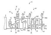
図1は、本発明が好適に適用される車両用動力伝達装置10の構成を説明する骨子図である。この動力伝達装置10は、例えば、FR(フロントエンジン・リヤドライブ)型車両において縦置きされて用いられるものであり、車体に取り付けられる非回転部材としてのトランスミッションケース12(以下、ケース12という)内において共通の軸心上に配設された入力軸14と、その入力軸14に直接に或いは図示しない脈動吸収ダンパ(振動減衰装置)等を介して間接に連結された差動部16と、その差動部16と駆動輪34(図6を参照)との間の動力伝達経路において伝達部材(伝動軸)18を介して直列に連結された自動変速部20と、その自動変速部20に連結された出力軸22とを、直列に備えている。ここで、上記差動部16から出力される駆動力(回転トルク)は、上記伝達部材18を介して上記自動変速部20へ伝達される。すなわち、その伝達部材18は、上記差動部16の出力回転要素として機能する。
FIG. 1 is a skeleton diagram illustrating a configuration of a vehicle
上記動力伝達装置10には、走行用の主動力源としてのエンジン8が設けられており、その出力軸(クランク軸)が上記入力軸14に直接に或いは図示しない脈動吸収ダンパを介して直接的に連結されている。このエンジン8は、例えば、気筒内噴射される燃料の燃焼によって駆動力を発生させるガソリンエンジン或いはディーゼルエンジン等の内燃機関である。また、上記エンジン8と一対の駆動輪34(図6を参照)との間には動力伝達経路の一部を構成する差動歯車装置(終減速機)32(図6を参照)が設けられており、上記エンジン8から出力された動力は上記差動部16、自動変速部20、差動歯車装置32、及び一対の車軸等を順次介して一対の駆動輪34へ伝達される。このように、本実施例の動力伝達装置10において上記エンジン8と差動部16とは直結されている。この直結はトルクコンバータやフルードカップリング等の流体式伝動装置を介することなく連結されているということであり、例えば上記脈動吸収ダンパ等を介する連結はこの直結に含まれる。なお、上記動力伝達装置10はその軸心に対して対称的に構成されているため、図1の骨子図においてはその下側が省略されている。
The
前記差動部16は、第1電動機M1と、第2電動機M2と、シングルピニオン型の第1遊星歯車装置24とを、備えて、その第1電動機M1の運転状態が制御されることにより入力回転速度と出力回転速度の差動状態が制御されるように構成されたものであり、上記第1電動機M1は上記第1遊星歯車装置24の回転要素としてのサンギヤS1(第2回転要素RE2)に、上記第2電動機M2は前記伝達部材18と一体的に回転させられる上記第1遊星歯車装置24のリングギヤR1(第3回転要素RE3)にそれぞれ連結されている。この差動部16は、換言すれば、上記第1電動機M1と、前記入力軸14から入力されるエンジン8の出力とを機械的に分配する機械的機構であって、エンジン出力を第1電動機M1及び伝達部材18に分配する差動機構としての動力分配機構36を構成している。上記第1電動機M1及び第2電動機M2は、好適には、電気エネルギから機械的な駆動力を発生させる原動機としての機能及び機械的な駆動力から電気エネルギを発生させる発電機としての機能を有する所謂モータジェネレータであるが、上記第1電動機M1は反力を発生させるためのジェネレータ(発電)機能を少なくとも備え、上記第2電動機M2は走行用の駆動力源として駆動力を出力するためのモータ(電動機)機能を少なくとも備える。すなわち、前記動力伝達装置10において、上記第2電動機M2は主動力源であるエンジン8の代替として、或いはそのエンジン8と共に走行用の駆動力を発生させる動力源(副動力源)として機能する。
The
上記第1遊星歯車装置24は、例えば「0.418」程度の所定のギヤ比ρ1を有するものであり、上記動力分配機構36は斯かる第1遊星歯車装置24を主体として構成されている。この第1遊星歯車装置24は、第1サンギヤS1、第1遊星歯車P1、その第1遊星歯車P1を自転及び公転可能に支持する第1キャリアCA1、第1遊星歯車P1を介して第1サンギヤS1と噛み合う第1リングギヤR1を回転要素(要素)として備えている。第1サンギヤS1の歯数をZS1、第1リングギヤR1の歯数をZR1とすると、上記ギヤ比ρ1はZS1/ZR1である。
The first
上記動力分配機構36において、第1キャリアCA1は前記入力軸14すなわちエンジン8に連結され、第1サンギヤS1は前記第1電動機M1に連結され、第1リングギヤR1は前記伝達部材18に連結されている。このように構成された上記動力分配機構36は、前記第1遊星歯車装置24に備えられた3つの回転要素である第1サンギヤS1、第1キャリアCA1、及び第1リングギヤR1がそれぞれ相互に相対回転可能とされて差動作用が作動可能な状態すなわち差動作用が働く差動状態とされることから、前記エンジン8から出力される駆動力が前記第1電動機M1と伝達部材18とに分配されると共に、分配された駆動力の一部で前記第1電動機M1により発電が行われたり、前記第2電動機M2が回転駆動されるというように、前記差動部16(動力分配機構36)は電気的な差動装置として機能させられる。これにより、例えば、前記差動部16は所謂無段変速状態(電気的CVT状態)とされて、前記エンジン8の所定回転にかかわらず前記伝達部材18の回転が連続的に変化させられる。すなわち、前記差動部16はその変速比γ0(入力軸14の回転速度NIN/伝達部材18の回転速度N18)が最小値γ0minから最大値γ0maxまで連続的に変化させられる電気的な無段変速機として機能する電気式差動部である。
In the
前記自動変速部20は、シングルピニオン型の第2遊星歯車装置26、シングルピニオン型の第3遊星歯車装置28、及びシングルピニオン型の第4遊星歯車装置30を備え、有段式の自動変速機として機能する遊星歯車式の多段変速機である。上記第2遊星歯車装置26は、第2サンギヤS2、第2遊星歯車P2、その第2遊星歯車P2を自転及び公転可能に支持する第2キャリアCA2、及び第2遊星歯車P2を介して第2サンギヤS2と噛み合う第2リングギヤR2を備えており、例えば「0.562」程度の所定のギヤ比ρ2を有している。また、上記第3遊星歯車装置28は、第3サンギヤS3、第3遊星歯車P3、その第3遊星歯車P3を自転及び公転可能に支持する第3キャリアCA3、及び第3遊星歯車P3を介して第3サンギヤS3と噛み合う第3リングギヤR3を備えており、例えば「0.425」程度の所定のギヤ比ρ3を有している。また、上記第4遊星歯車装置30は、第4サンギヤS4、第4遊星歯車P4、その第4遊星歯車P4を自転及び公転可能に支持する第4キャリアCA4、及び第4遊星歯車P4を介して第4サンギヤS4と噛み合う第4リングギヤR4を備えており、例えば「0.421」程度の所定のギヤ比ρ4を有している。上記第2サンギヤS2の歯数をZS2、上記第2リングギヤR2の歯数をZR2、上記第3サンギヤS3の歯数をZS3、上記第3リングギヤR3の歯数をZR3、上記第4サンギヤS4の歯数をZS4、上記第4リングギヤR4の歯数をZR4とすると、上記ギヤ比ρ2はZS2/ZR2、上記ギヤ比ρ3はZS3/ZR3、上記ギヤ比ρ4はZS4/ZR4である。
The
また、前記自動変速部20は、その自動変速部20において所定の変速段を成立させるための複数の係合要素として、第1クラッチC1、第2クラッチC2、第1ブレーキB1、第2ブレーキB2、及び第3ブレーキB3(以下、特に区別しない場合はクラッチC、ブレーキBと表す)を備えている。これらクラッチC及びブレーキBは、何れも従来の車両用自動変速機においてよく用いられている係合要素としての油圧式摩擦係合装置であって、互いに重ねられた複数枚の摩擦板が油圧アクチュエータにより押圧される湿式多板型や、回転するドラムの外周面に巻き付けられた1本又は2本のバンドの一端が油圧アクチュエータによって引き締められるバンドブレーキ等により構成され、それが介挿されている両側の部材を選択的に連結するための装置である。
The
以上のように構成された自動変速部20では、上記第2サンギヤS2と第3サンギヤS3とが一体的に連結されており、第2クラッチC2を介して前記伝達部材18に選択的に連結されると共に第1ブレーキB1を介して前記ケース12に選択的に連結されるようになっている。また、上記第2キャリアCA2は第2ブレーキB2を介して前記ケース12に選択的に連結されるようになっている。また、上記第4リングギヤR4は第3ブレーキB3を介して前記ケース12に選択的に連結されるようになっている。また、上記第2リングギヤR2と第3キャリアCA3と第4キャリアCA4とが一体的に連結されて出力軸22に連結されている。また、上記第3リングギヤR3と第4サンギヤS4とが一体的に連結されており、第1クラッチC1を介して前記伝達部材18に選択的に連結されるようになっている。
In the
このように、前記自動変速部20内と差動部16(伝達部材18)とは、その自動変速部20の各ギヤ段(変速段)を成立させるために用いられる第1クラッチC1及び/又は第2クラッチC2を介して選択的に連結されるようになっている。換言すれば、斯かる第1クラッチC1及び第2クラッチC2は、前記伝達部材18と自動変速部20との間の動力伝達経路すなわち差動部16(伝達部材18)から駆動輪34への動力伝達経路を、その動力伝達経路の動力伝達を可能とする動力伝達可能状態と、その動力伝達経路の動力伝達を遮断する動力伝達遮断状態とに選択的に切り換える係合装置として機能している。つまり、上記第1クラッチC1及び第2クラッチC2の少なくとも一方が係合されることで上記動力伝達経路が動力伝達可能状態とされた車両の駆動状態とされ、上記第1クラッチC1及び第2クラッチC2が共に解放されることで上記動力伝達経路が動力伝達遮断状態とされた車両の非駆動状態とされる。すなわち、本実施例の動力伝達装置10において、前記自動変速部20に備えられた複数の摩擦係合要素のうち、少なくとも第1クラッチC1及び第2クラッチC2が動力断続要素に対応する。
As described above, the
前記自動変速部20では、解放側係合装置の解放と係合側係合装置の係合とによりクラッチ・ツウ・クラッチ変速が実行されて各ギヤ段が選択的に成立させられることにより、略等比的に変化する変速比γ(=伝達部材18の回転速度N1N/出力軸22の回転速度NOUT)が各ギヤ段毎に得られる。例えば、図2の係合作動表に示されるように、第1クラッチC1及び第3ブレーキB3の係合により変速比γ1が最大値例えば「3.357」程度である第1速ギヤ段が成立させられる。また、第1クラッチC1及び第2ブレーキB2の係合により変速比γ2が第1速ギヤ段よりも小さい値例えば「2.180」程度である第2速ギヤ段が成立させられる。また、第1クラッチC1及び第1ブレーキB1の係合により変速比γ3が第2速ギヤ段よりも小さい値例えば「1.424」程度である第3速ギヤ段が成立させられる。また、第1クラッチC1及び第2クラッチC2の係合により変速比γ4が第3速ギヤ段よりも小さい値例えば「1.000」程度である第4速ギヤ段が成立させられる。また、第2クラッチC2及び第3ブレーキB3の係合により変速比γRが第1速ギヤ段と第2速ギヤ段との間の値例えば「3.209」程度である後進ギヤ段(後進変速段)が成立させられる。また、第1クラッチC1、第2クラッチC2、第1ブレーキB1、第2ブレーキB2、及び第3ブレーキB3の解放によりニュートラル「N」状態とされる。
In the
以上のように構成された動力伝達装置10において、無段変速機として機能する前記差動部16と有段変速機として機能する自動変速部20とで全体として無段変速機が構成される。また、前記差動部16の変速比を一定となるように制御することにより、その差動部16と自動変速部20とで有段変速機と同等の状態を構成することが可能とされる。具体的には、前記差動部16が無段変速機として機能し、且つその差動部16に直列の前記自動変速部20が有段変速機として機能することにより、その自動変速部20の少なくとも1つの変速段Mに対してその自動変速部20に入力される回転速度すなわち前記伝達部材18の回転速度が無段的に変化させられてその変速段Mにおいて無段的な変速比幅が得られる。従って、前記動力伝達装置10の総合変速比γT(=入力軸14の回転速度NIN/出力軸22の回転速度NOUT)が無段階に得られ、前記動力伝達装置10において無段変速機が構成される。この動力伝達装置10の総合変速比γTは、前記差動部16の変速比γ0と前記自動変速部20の変速比γとに基づいて形成される前記動力伝達装置10全体としてのトータル変速比γTである。
In the
例えば、図2の係合作動表に示される前記自動変速部20の第1速ギヤ段乃至第4速ギヤ段や後進ギヤ段の各ギヤ段に対して前記伝達部材18の回転速度が無段的に変化させられて各ギヤ段は無段的な変速比幅が得られる。従って、各ギヤ段の間が無段的に連続変化可能な変速比となって、前記動力伝達装置10全体としてのトータル変速比γTが無段階に得られる。また、前記差動部16の変速比が一定となるように制御され、且つクラッチC及びブレーキBが選択的に係合作動させられて第1速ギヤ段乃至第4速ギヤ段の何れか或いは後進ギヤ段(後進変速段)が選択的に成立させられることにより、略等比的に変化する前記動力伝達装置10のトータル変速比γTが各ギヤ段毎に得られる。従って、前記動力伝達装置10において有段変速機と同等の状態が構成される。例えば、前記差動部16の変速比γ0が「1」に固定されるように制御されると、図2の係合作動表に示されるように前記自動変速部20の第1速ギヤ段乃至第4速ギヤ段や後進ギヤ段の各ギヤ段に対応する前記動力伝達装置10のトータル変速比γTが各ギヤ段毎に得られる。また、前記自動変速部20の第4速ギヤ段において前記差動部16の変速比γ0が「1」より小さい値例えば0.7程度に固定されるように制御されると、第4速ギヤ段よりも小さい値例えば「0.7」程度であるトータル変速比γTが得られる。
For example, the rotational speed of the
図3は、前記差動部16及び自動変速部20から構成される動力伝達装置10において、ギヤ段毎に連結状態が異なる各回転要素の回転速度の相対関係を直線上で表すことができる共線図を示している。この図3の共線図は、前記第1遊星歯車装置24、第2遊星歯車装置26、第3遊星歯車装置28、及び第4遊星歯車装置30それぞれのギヤ比ρの関係を示す横軸と、相対的回転速度を示す縦軸とから成る二次元座標であり、横線X1が回転速度零を示し、横線X2が回転速度「1.0」すなわち前記入力軸14に連結された前記エンジン8の回転速度NEを示し、横線XGが前記伝達部材18の回転速度を示している。また、前記差動部16を構成する前記動力分配機構36の3つの要素に対応する3本の縦線Y1、Y2、Y3は、左側から順に第2回転要素(第2要素)RE2に対応する第1サンギヤS1、第1回転要素(第1要素)RE1に対応する第1キャリアCA1、第3回転要素(第3要素)RE3に対応する第1リングギヤR1の相対回転速度を示すものであり、それらの間隔は前記第1遊星歯車装置24のギヤ比ρ1に応じて定められている。更に、前記自動変速部20に対応する5本の縦線Y4、Y5、Y6、Y7、Y8は、左から順に、第4回転要素(第4要素)RE4に対応し且つ相互に連結された第2サンギヤS2及び第3サンギヤS3、第5回転要素(第5要素)RE5に対応する第2キャリアCA2、第6回転要素(第6要素)RE6に対応する第4リングギヤR4、第7回転要素(第7要素)RE7に対応し且つ相互に連結された第2リングギヤR2、第3キャリアCA3、第4キャリアCA4、第8回転要素(第8要素)RE8に対応し且つ相互に連結された第3リングギヤR3、第4サンギヤS4の相対回転速度を示すものであり、それらの間隔は前記第2遊星歯車装置26、第3遊星歯車装置28、及び第4遊星歯車装置30のギヤ比ρ2、ρ3、ρ4に応じてそれぞれ定められている。ここで、共線図の縦軸間の関係においてサンギヤとキャリアとの間が「1」に対応する間隔とされるとキャリアとリングギヤとの間が遊星歯車装置のギヤ比ρに対応する間隔とされる。すなわち、前記差動部16では縦線Y1とY2との縦線間が「1」に対応する間隔に設定され、縦線Y2とY3との間隔はギヤ比ρ1に対応する間隔に設定される。また、前記自動変速部20では前記第2遊星歯車装置26、第3遊星歯車装置28、及び第4遊星歯車装置30毎にそのサンギヤとキャリアとの間が「1」に対応する間隔に設定され、キャリアとリングギヤとの間がρに対応する間隔に設定される。
FIG. 3 shows a linear relationship between the rotational speeds of the rotary elements having different coupling states for each gear stage in the
図3の共線図を用いて表現すれば、本実施例の動力伝達装置10は、前記動力分配機構36(差動部16)において、前記第1遊星歯車装置24の第1回転要素RE1(第1キャリアCA1)が前記入力軸14すなわちエンジン8の出力軸に連結されている。また、第2回転要素RE2が前記第1電動機M1に連結されている。また、第3回転要素(第1リングギヤR1)RE3が前記伝達部材18及び第2電動機M2に連結されており、前記入力軸14の回転を伝達部材18を介して自動変速部20へ伝達する(入力させる)ように構成されている。この図3においては、Y2とX2の交点を通る斜めの直線L0により第1サンギヤS1の回転速度と第1リングギヤR1の回転速度との関係が示される。例えば、前記差動部16においては、第1回転要素RE1乃至第3回転要素RE3が相互に相対回転可能とされる差動状態とされており、直線L0と縦線Y3との交点で示される第1リングギヤR1の回転速度が車速Vに拘束されて略一定である場合には、前記エンジン回転速度NEを制御することによって直線L0と縦線Y2との交点で示される第1キャリアCA1の回転速度が上昇或いは下降させられると、直線L0と縦線Y1との交点で示される第1サンギヤS1の回転速度すなわち第1電動機M1の回転速度が上昇或いは下降させられる。また、前記差動部16の変速比γ0が「1」に固定されるように前記第1電動機M1の回転速度を制御することによって第1サンギヤS1の回転がエンジン回転速度NEと同じ回転とされると、直線L0は横線X2と一致させられ、エンジン回転速度NEと同じ回転で第1リングギヤR1の回転速度すなわち前記伝達部材18が回転させられる。また、前記差動部16の変速比γ0が「1」より小さい値例えば0.7程度に固定されるように前記第1電動機M1の回転速度を制御することによって第1サンギヤS1の回転が零とされると、エンジン回転速度NEよりも増速された速度で前記伝達部材18が回転させられる。
If expressed using the collinear diagram of FIG. 3, the
また、図3の共線図では、前記自動変速部20において第4回転要素RE4は第2クラッチC2を介して前記伝達部材18に選択的に連結されると共に第1ブレーキB1を介して前記ケース12に選択的に連結されている。また、第5回転要素RE5は第2ブレーキB2を介して前記ケース12に選択的に連結されている。また、第6回転要素RE6は第3ブレーキB3を介して前記ケース12に選択的に連結されている。また、第7回転要素RE7は前記出力軸22に連結されている。また、第8回転要素RE8は第1クラッチC1を介して前記伝達部材18に選択的に連結されている。前記自動変速部20では、前記差動部16において直線L0が横線X2と一致させられてエンジン回転速度NEと同じ回転速度がその差動部16から第8回転要素RE8に入力されると、図3に示すように、第1クラッチC1と第3ブレーキB3とが係合させられることにより、第8回転要素RE8の回転速度を示す縦線Y8と横線X2との交点と第6回転要素RE6の回転速度を示す縦線Y6と横線X1との交点とを通る斜めの直線L1と、前記出力軸22と連結された第7回転要素RE7の回転速度を示す縦線Y7との交点で第1速(1st)の出力軸22の回転速度が示される。同様に、第1クラッチC1と第2ブレーキB2とが係合させられることにより決まる斜めの直線L2と前記出力軸22と連結された第7回転要素RE7の回転速度を示す縦線Y7との交点で第2速(2nd)の前記出力軸22の回転速度が示される。また、第1クラッチC1と第1ブレーキB1とが係合させられることにより決まる斜めの直線L3と前記出力軸22と連結された第7回転要素RE7の回転速度を示す縦線Y7との交点で第3速(3rd)の出力軸22の回転速度が示される。また、第1クラッチC1と第2クラッチC2とが係合させられることにより決まる水平な直線L4と前記出力軸22と連結された第7回転要素RE7の回転速度を示す縦線Y7との交点で第4速(4th)の出力軸22の回転速度が示される。
In the collinear diagram of FIG. 3, in the
図4は、前記動力伝達装置10を制御するためにその動力伝達装置10に備えられた電子制御装置40に入力される信号及びその電子制御装置40から出力される信号を例示している。この電子制御装置40は、CPU、ROM、RAM、及び入出力インターフェース等から成る所謂マイクロコンピュータを含んで構成されており、RAMの一時記憶機能を利用しつつROMに予め記憶されたプログラムに従って信号処理を行うことにより前記エンジン8の駆動制御、そのエンジン8、第1電動機M1、及び第2電動機M2によるハイブリッド駆動制御、及び前記自動変速部20による変速制御等の各種制御を実行するものである。
FIG. 4 illustrates a signal input to the
図4に示すように、上記電子制御装置40には、各センサやスイッチ等から前記動力伝達装置10に関する各種信号が供給されるようになっている。例えば、エンジン水温を表す信号、シフトレバー52(図5を参照)のシフトポジションや「M」ポジションにおける操作回数等を表す信号、蓄電装置56(図6を参照)の温度を表す信号、その蓄電装置56の充電容量(充電状態)SOCを表す信号、前記第1電動機M1の回転速度NM1を表す信号、前記第2電動機M2の回転速度NM2を表す信号、前記エンジン8の回転速度であるエンジン回転速度NEを表す信号、各車輪の車輪速を表す信号、Mモード(手動変速走行モード)スイッチのオン・オフを表す信号、エアコンの作動を表す信号、車速Vに対応する前記出力軸22の回転速度NOUTを表す信号、前記自動変速部20の制御作動に用いられるATF温度を表す信号、サイドブレーキ操作を表す信号、フットブレーキ操作を表す信号、そのフットブレーキに対応するブレーキマスタシリンダ圧を表す信号、触媒温度を表す信号、運転者の出力要求量に対応するアクセルペダルの操作量であるアクセル開度Accを表す信号、カム角を表す信号、スノーモード設定を表す信号、車両の前後加速度Gを表す信号、オートクルーズ走行を表す信号、車両の重量(車重)を表す信号等がそれぞれ供給される。
As shown in FIG. 4, the
また、前記動力伝達装置10の駆動を制御するために、前記電子制御装置40から各種制御信号が出力されるようになっている。例えば、前記エンジン8の吸気管60に備えられた電子スロットル弁62のスロットル弁開度θTHを操作するスロットルアクチュエータ64への駆動信号や燃料噴射装置66による吸気管60或いはエンジン8の筒内への燃料供給量を制御する燃料供給量信号や点火装置68による前記エンジン8の点火時期を指令する点火信号、過給圧を調整するための過給圧調整信号等、エンジン出力を制御するエンジン出力制御装置58(図6を参照)への制御信号、電動エアコンを作動させるための電動エアコン駆動信号、前記第1電動機M1及び第2電動機M2の作動を指令する指令信号、シフトインジケータを作動させるためのシフトポジション(操作位置)表示信号、ギヤ比を表示させるためのギヤ比表示信号、スノーモードであることを表示させるためのスノーモード表示信号、制動時の車輪のスリップを防止するABSアクチュエータを作動させるためのABS作動信号、Mモードが選択されていることを表示させるMモード表示信号、前記差動部16や自動変速部20に備えられた油圧式摩擦係合装置の油圧アクチュエータを制御するために油圧制御回路38(図6を参照)に含まれる電磁弁(リニアソレノイドバルブ)を作動させるバルブ指令信号、その油圧制御回路38に設けられたレギュレータバルブ(調圧弁)によりライン油圧PLを調圧するための信号、そのライン油圧PLが調圧されるための元圧の油圧源である電動油圧ポンプを作動させるための駆動指令信号、電動ヒータを駆動するための信号、クルーズコントロール制御用コンピュータへの信号、駆動力源の出力(以下、駆動力源出力という)を抑制中例えばエンジン出力(パワー)及び/又は第2電動機M2の出力(以下、第2電動機出力という)を抑制中であることを運転者に知らせるための出力抑制中信号等がそれぞれ出力される。
Various control signals are output from the
図5は、前記動力伝達装置10において複数種類のシフトポジションPSHを人為的操作により切り換える切換装置としてのシフト操作装置50の一例を示す図である。このシフト操作装置50は、例えば運転席の横に配設され、複数種類のシフトポジションPSHを選択するために操作されるシフトレバー52を備えている。そのシフトレバー52は、前記動力伝達装置10(自動変速部20)内の動力伝達経路が遮断されたニュートラル状態すなわち中立状態とし且つ自動変速部20の出力軸22をロックするための駐車ポジション「P(パーキング)」、後進走行のための後進走行ポジション「R(リバース)」、前記動力伝達装置10内の動力伝達経路が遮断された中立状態とするための中立ポジション「N(ニュートラル)」、自動変速モードを成立させて前記差動部16の無段的な変速比幅と自動変速部20の第1速ギヤ段乃至第4速ギヤ段の範囲で自動変速制御される各ギヤ段とで得られる前記動力伝達装置10の変速可能なトータル変速比γTの変化範囲内で自動変速制御を実行させる前進自動変速走行ポジション「D(ドライブ)」、又は手動変速走行モード(手動モード)を成立させて前記自動変速部20の自動変速制御における高速側の変速段を制限する所謂変速レンジを設定するための前進手動変速走行ポジション「M(マニュアル)」へ手動操作されるように設けられている。
FIG. 5 is a diagram illustrating an example of a
前記動力伝達装置10では、上記シフトレバー52の各シフトポジションPSHへの手動操作に連動して前述した図2の係合作動表に示す後進ギヤ段「R」、ニュートラル「N」、前進ギヤ段「D」における各変速段等が成立するように、例えば前記油圧制御回路38における回路が電気的に切り換えられる。また、上記「P」乃至「M」ポジションに示す各シフトポジションPSHに関して、「P」ポジション及び「N」ポジションは、車両を走行させないときに選択される非走行ポジションであって、例えば図2の係合作動表に示されるように第1クラッチC1及び第2クラッチC2の何れもが解放されるような前記自動変速部20内の動力伝達経路が遮断された車両を駆動不能とする第1クラッチC1及び第2クラッチC2による動力伝達経路の動力伝達遮断状態へ切換えを選択するための非駆動ポジションである。また、「R」ポジション、「D」ポジション、及び「M」ポジションは、車両の走行に際して選択される走行ポジションであって、例えば図2の係合作動表に示されるように第1クラッチC1及び第2クラッチC2の少なくとも一方が係合されるような前記自動変速部20内の動力伝達経路が連結された車両を駆動可能とする第1クラッチC1及び/又は第2クラッチC2による動力伝達経路の動力伝達可能状態への切換えを選択するための駆動ポジションでもある。
Wherein the
図5に示すシフト操作装置50において、具体的には、前記シフトレバー52が「P」ポジション或いは「N」ポジションから「R」ポジションへ手動操作されることで、第2クラッチC2が係合されて前記自動変速部20内の動力伝達経路が動力伝達遮断状態から動力伝達可能状態とされる。また、前記シフトレバー52が「N」ポジションから「D」ポジションへ手動操作されることで、少なくとも第1クラッチC1が係合されて前記自動変速部20内の動力伝達経路が動力伝達遮断状態から動力伝達可能状態とされる。また、前記シフトレバー52が「R」ポジションから「P」ポジション或いは「N」ポジションへ手動操作されることで、第2クラッチC2が解放されて前記自動変速部20内の動力伝達経路が動力伝達可能状態から動力伝達遮断状態とされる。また、前記シフトレバー52が「D」ポジションから「N」ポジションへ手動操作されることで、第1クラッチC1及び第2クラッチC2が解放されて前記自動変速部20内の動力伝達経路が動力伝達可能状態から動力伝達遮断状態とされる。
In the
図6は、前記電子制御装置40に備えられた制御機能の要部を説明する機能ブロック線図である。この図6に示す変速制御手段80は、電気式無段変速機としての差動部16及び有段式変速機としての自動変速部20から構成される前記動力伝達装置10の変速比を制御する。このために、前記自動変速部20を制御するための有段変速制御手段82と、前記エンジン8、第1電動機M1、及び第2電動機M2等を介して前記差動部16を制御するためのハイブリッド制御手段84とを、備えている。
FIG. 6 is a functional block diagram for explaining a main part of the control function provided in the
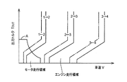
上記有段変速制御手段82は、例えば図7に示すような車速Vと自動変速部20の出力トルクTOUTとを変数として予め記憶されたアップシフト線(実線)及びダウンシフト線(一点鎖線)を有する関係(変速線図、変速マップ)から、実際の車速V及び自動変速部20の要求出力トルクTOUTで示される車両状態に基づいて、前記自動変速部20の変速を実行すべきか否かを判断しすなわちその自動変速部20の変速すべき変速段を判断し、その判断した変速段が得られるように前記自動変速部20の自動変速制御を実行する。具体的には、例えば図2に示す係合表に従って変速段が達成されるように、前記自動変速部20の変速に関与する油圧式摩擦係合装置を係合及び/又は解放させる指令(変速出力指令、油圧指令)を前記油圧制御回路38へ出力する。換言すれば、前記自動変速部20の変速に関与する解放側係合装置を解放すると共に係合側係合装置を係合することによりクラッチ・ツウ・クラッチ変速を実行させる指令を前記油圧制御回路38へ出力する。前記油圧制御回路38は、そのようにして出力される指令に従って、例えば解放側係合装置を解放すると共に係合側係合装置を係合して前記自動変速部20の変速が実行されるようにリニアソレノイドバルブSLを作動させてその変速に関与する油圧式摩擦係合装置の油圧アクチュエータを作動させる。
The stepped shift control means 82 includes, for example, an upshift line (solid line) and a downshift line (one-dot chain line) stored in advance using the vehicle speed V and the output torque T OUT of the
前記ハイブリッド制御手段84は、前記差動部16の作動を制御する差動部制御手段であり、前記エンジン8を効率のよい作動域で作動させる一方で、そのエンジン8と第2電動機M2との駆動力の配分や前記第1電動機M1の発電による反力を最適になるように変化させて前記差動部16の電気的な無段変速機としての変速比γ0を制御する。例えば、その時点における走行車速Vにおいて、運転者の出力要求量としてのアクセル開度Accや車速Vから車両の目標(要求)出力を算出し、その車両の目標出力と充電要求値から必要なトータル目標出力を算出し、そのトータル目標出力が得られるように伝達損失、補機負荷、前記第2電動機M2のアシストトルク等を考慮して目標エンジン出力を算出し、その目標エンジン出力が得られるエンジン回転速度NE及びエンジントルクTEとなるように前記エンジン8を制御すると共に前記第1電動機M1の発電量を制御する。
The
以上のように、前記動力伝達装置10全体としての変速比である総合変速比γTは、前記有段変速制御手段82によって制御される自動変速部20の変速比γと、前記ハイブリッド制御手段84によって制御される前記差動部16の変速比γ0とによって決定される。すなわち、前記変速制御手段80は、運転者による前記シフトレバー52の操作に従い、前記シフト操作装置50から出力されるシフトポジションを表す信号PSHに基づいて、例えばシフトポジションPSHに対応するシフトレンジの範囲内において、前記有段変速制御手段82及びハイブリッド制御手段84を介して前記動力伝達装置10全体としての変速比である総合変速比γTを制御する。
As described above, the overall transmission ratio γT, which is the overall transmission ratio of the
前記ハイブリッド制御手段84は、例えば、前記動力伝達装置10の動力性能や燃費向上等を考慮して前記ハイブリッド変速制御を実行する。すなわち、前記エンジン8を効率のよい作動域で作動させるために定まるエンジン回転速度NEと車速V及び自動変速部20の変速段で定まる前記伝達部材18の回転速度とを整合させるために前記差動部16を電気的な無段変速機として機能させる。換言すれば、前記ハイブリッド制御手段84は、エンジン回転速度NEとエンジントルクTEとで構成される二次元座標内において無段変速走行の時に運転性と燃費性とを両立するように予め実験的に求められて記憶された最適燃費率曲線に沿って前記エンジン8が作動させられるように、例えば目標出力を充足するために必要なエンジン出力を発生するためのエンジントルクTEとエンジン回転速度NEとなるように前記動力伝達装置10のトータル変速比γTの目標値を定め、その目標値が得られるように前記自動変速部20の変速段を考慮して前記差動部16の変速比γ0を制御し、トータル変速比γTをその変速可能な変化範囲内で無段階に制御する。
The hybrid control means 84 executes the hybrid shift control in consideration of, for example, power performance and fuel efficiency improvement of the
このとき、前記ハイブリッド制御手段84は、前記第1電動機M1により発電された電気エネルギをインバータ54を通して蓄電装置56や第2電動機M2へ供給するので、前記エンジン8の動力の主要部は機械的に前記伝達部材18へ伝達されるが、そのエンジン8の動力の一部は前記第1電動機M1の発電のために消費されてそこで電気エネルギに変換され、上記インバータ54を通してその電気エネルギが前記第2電動機M2へ供給され、その第2電動機M2が駆動されて第2電動機M2から前記伝達部材18へ伝達される。この電気エネルギの発生から前記第2電動機M2で消費されるまでに関連する機器により、前記エンジン8の動力の一部が電気エネルギに変換され、その電気エネルギを機械的エネルギに変換するまでの電気パスが構成される。特に、前記有段変速制御手段82により前記自動変速部20の変速制御が実行される場合には、その自動変速部20の変速比が段階的に変化させられることに伴ってその変速前後で前記動力伝達装置10のトータル変速比γTが段階的に変化させられる。
At this time, the hybrid control means 84 supplies the electric energy generated by the first electric motor M1 to the
上述のような制御では、トータル変速比γTが段階的に変化することにより、すなわち変速比が連続的ではなく飛び飛びの値をとることにより、連続的なトータル変速比γTの変化に比較して速やかに駆動トルクを変化させることが可能となる。その反面、変速ショックが発生したり、最適燃費率曲線に沿うようにエンジン回転速度NEを制御できず燃費が悪化する可能性がある。そこで、前記ハイブリッド制御手段84は、そのトータル変速比γTの段階的変化が抑制されるように、前記自動変速部20の変速に同期してその自動変速部20の変速比の変化方向とは反対方向の変速比の変化となるように前記差動部16の変速を実行する。換言すれば、前記自動変速部20の変速前後で前記動力伝達装置10のトータル変速比γTが連続的に変化するように前記自動変速部20の変速制御に同期して前記差動部16の変速制御を実行する。例えば、前記自動変速部20の変速前後で過渡的に前記動力伝達装置10のトータル変速比γTが変化しないような所定のトータル変速比γTを形成するために前記自動変速部20の変速制御に同期して、その自動変速部20の変速比の段階的な変化に相当する変化分だけその変化方向とは反対方向に変速比を段階的に変化させるように前記差動部16の変速制御を実行する。
In the control as described above, the total speed ratio γT changes stepwise, that is, the speed ratio is not continuous but takes a jump value, so that it is quicker than the continuous total speed ratio γT. It becomes possible to change the driving torque. On the other hand, there is a possibility that the shift shock may occur, fuel economy can not control the engine rotational speed N E along the optimum fuel consumption curve deteriorate. Therefore, the hybrid control means 84 is opposite to the direction of change of the gear ratio of the
また、前記ハイブリッド制御手段84は、車両の停止中又は走行中にかかわらず、前記差動部16の電気的CVT機能によって、例えば前記第1電動機M1の回転速度NM1を制御してエンジン回転速度NEを略一定に維持したり、任意の回転速度に制御したりというように、前記第1電動機M1を介して前記エンジン8の回転速度を制御する。例えば、前述した図3の共線図からもわかるように、車両走行中にエンジン回転速度NEを引き上げる場合には、車速V(駆動輪34の回転速度)に対応する前記第2電動機M2の回転速度NM2を略一定に維持しつつ前記第1電動機M1の回転速度NM1の引き上げを実行する。すなわち、主動力源である前記エンジン8の回転速度NEを前記第1電動機M1により制御している状態とは、そのエンジン8の始動制御時又は停止制御時、或いは第1電動機M1による発電時である。
Further, the hybrid control means 84 controls, for example, the rotational speed N M1 of the first electric motor M1 by means of the electric CVT function of the
また、前記ハイブリッド制御手段84は、スロットル制御のために前記スロットルアクチュエータ64を介して前記電子スロットル弁62を開閉制御させる他、燃料噴射制御のために前記燃料噴射装置66による燃料噴射量や噴射時期を制御させ、点火時期制御のためにイグナイタ等の点火装置68による点火時期を制御させる指令を単独で或いは組み合わせて前記エンジン出力制御装置58に出力し、必要なエンジン出力を発生するように前記エンジン8の出力制御を実行するエンジン出力制御を実行する。例えば、基本的には図示しない予め記憶された関係からアクセル開度Accに基づいて前記スロットルアクチュエータ64を駆動し、アクセル開度Accが増加するほどスロットル弁開度θTHを増加させるようにスロットル制御を実行する。また、前記エンジン出力制御装置58は、前記ハイブリッド制御手段84による指令に従ってスロットル制御のために前記スロットルアクチュエータ64により前記電子スロットル弁62を開閉制御する他、燃料噴射制御のために前記燃料噴射装置66による燃料噴射を制御し、点火時期制御のためにイグナイタ等の上記点火装置68による点火時期を制御する等してエンジントルク制御を実行する。
The hybrid control means 84 controls the opening and closing of the
また、前記ハイブリッド制御手段84は、前記エンジン8の停止又はアイドル状態にかかわらず、前記差動部16の電気的CVT機能(差動作用)によって車両をモータ走行させる。例えば、図7に示すような車速Vと前記自動変速部20の出力トルクTOUTとを変数として予め記憶された、走行用の駆動力源を前記エンジン8と第2電動機M2とで切り換えるためのエンジン走行領域とモータ走行領域との境界線を有する関係(駆動力源切換線図、駆動力源マップ)から、実際の車速V及び前記自動変速部20の要求出力トルクTOUTで示される車両状態に基づいて、モータ走行領域とエンジン走行領域との何れであるかを判断してモータ走行或いはエンジン走行を実行する。図7の実線Aに示す駆動力源マップは、例えばその図7における実線及び一点鎖線に示す変速マップと共に予め記憶されたものである。この図7から明らかなように、前記ハイブリッド制御手段84によるモータ走行制御は、一般的にエンジン効率が高トルク域に比較して悪いとされる比較的低出力トルクTOUT域すなわち低エンジントルクTE域、或いは車速Vの比較的低車速域すなわち低負荷域で実行される。
In addition, the hybrid control means 84 causes the vehicle to run on a motor by the electric CVT function (differential action) of the
斯かるモータ走行制御に際して、前記ハイブリッド制御手段84は、停止している前記エンジン8の引き摺りを抑制して燃費を向上させるために、前記第1電動機M1の回転速度NM1を負の回転速度で制御して例えばその第1電動機M1を無負荷状態とすることにより空転させ、前記差動部16の電気的CVT機能(差動作用)により必要に応じてエンジン回転速度NEを零乃至略零に維持する。また、エンジン走行領域であっても、前述した電気パスによる前記第1電動機M1からの電気エネルギ及び/又は前記蓄電装置56からの電気エネルギを前記第2電動機M2へ供給し、その第2電動機M2を駆動して前記駆動輪34にトルクを付与することにより、前記エンジン8の動力を補助するための所謂トルクアシストが可能である。また、前記第1電動機M1を無負荷状態として自由回転すなわち空転させることにより、前記差動部16がトルクの伝達を不能な状態すなわちその差動部16内の動力伝達経路が遮断された状態と同等の状態であって、且つその差動部16からの出力が発生されない状態とすることが可能である。すなわち、前記ハイブリッド制御手段84は、前記第1電動機M1を無負荷状態とすることにより前記差動部16をその動力伝達経路が電気的に遮断される中立状態(ニュートラル状態)とすることが可能である。
In such motor travel control, the hybrid control means 84 sets the rotation speed N M1 of the first electric motor M1 at a negative rotation speed in order to improve drag while suppressing dragging of the stopped
このように、図7に示すような駆動力源マップにおいては、モータ走行領域は一般的にエンジン効率が高トルク域に比較して悪いとされる比較的低トルク出力トルクTOUT域、或いは車速Vの比較的低車速域すなわち低負荷域で実行されるように定められている。また、図7には示されていないが、「R」ポジション、すなわち車両を後退させる場合においても、比較的低車速で走行するものであるから、前記エンジン8を用いず前記第2電動機M2によって走行するようにされている。従って、例えば所定の低車速時や車両停止時等に前記シフトレバー52「N」ポジションから「D」ポジション或いは「R」ポジションへ操作されるガレージシフト(N→Dシフト、N→Rシフト或いはP→Rシフト)が行なわれる際には、前記ハイブリッド制御手段84は、エンジンではなくモータによる動力によって車両を走行させる制御を行う。
Thus, in the driving force source map as shown in FIG. 7, the motor travel region is generally a relatively low torque output torque T OUT region, or vehicle speed, which is generally considered to be poorer in engine efficiency than the high torque region. It is determined to be executed in a relatively low vehicle speed range of V, that is, a low load range. Although not shown in FIG. 7, even in the “R” position, that is, when the vehicle is moved backward, the vehicle travels at a relatively low vehicle speed, so that the second electric motor M <b> 2 does not use the
図6に戻って、係合完了判定手段86は、前記動力伝達装置10を非駆動状態から駆動状態へ切り換えるための動力断続要素である第1クラッチC1及び/又は第2クラッチC2の係合の完了すなわち完全係合を判定する。この完全係合とは、前記伝達部材18の回転トルクが前記自動変速部20へ略100%伝達される状態となった場合をいう。上記係合完了判定手段86は、好適には、予め定められた関係から、前記ハイブリッド制御手段84により前記第1クラッチC1及び/又は第2クラッチC2を係合させるための係合指令が出力され始めてからの経過時間に基づいて、それら第1クラッチC1及び/又は第2クラッチC2の係合の完了を判定する。具体的には、予め実験的に求められて記憶された、係合指令が出力され始めてから前記第1クラッチC1及び/又は第2クラッチC2の係合が完了するまでの時間Tcompに基づいて、係合指令が出力されてからの実際の経過時間がその時間Tcompに達した段階で前記第1クラッチC1及び/又は第2クラッチC2の係合の完了を判定する。
Returning to FIG. 6, the engagement completion determination means 86 engages the first clutch C <b> 1 and / or the second clutch C <b> 2 that is a power interrupting element for switching the
発進要求判定手段88は、運転者の運転操作による発進要求の有無を判定する。好適には、フットブレーキ42の操作によりブレーキスイッチ44からブレーキオフ信号が供給された場合に、運転者による発進要求があったと判定する。また、好適には、ブレーキマスタシリンダ圧センサ46により検出される、上記フットブレーキ42の踏込量に対応するブレーキマスタシリンダ圧が所定値以下である場合に、運転者による発進要求があったと判定する。また、好適には、車速センサ48により検出される、前記駆動輪34の回転速度に相当する車速Vが所定値以上である場合に、運転者による発進要求があったと判定する。上記発進要求判定手段88は、好適には、それらブレーキスイッチによる判定、ブレーキマスターシリンダ圧による判定、車速による判定の少なくとも1つに基づいて発進要求を判定するものであるが、上記判定のうち2つが成立した場合に発進要求があったと判定するというように、それらの判定を組み合わせて複合的に運転者の発進要求を判定するものであってもよい。また、図示しないアクセルペダルの踏込量に相当するアクセル開度Accに基づいて斯かる判定を行うものであっても構わない。
The start request determination means 88 determines whether or not there is a start request due to the driving operation of the driver. Preferably, when a brake-off signal is supplied from the
前記ハイブリッド制御手段84は、前記動力伝達装置10(自動変速部20)が非駆動状態から駆動状態へ切り換えられている間の状態すなわち前記第1クラッチC1及び/又は第2クラッチC2の係合制御の実行中(係合開始から係合完了までの間)において、前記係合完了判定手段86により動力断続要素である第1クラッチC1及び/又は第2クラッチC2の係合の完了が判定されるまでの間、前記差動部16の出力回転速度を予め定められた一定の値に保持する回転速度保持制御を実行する。換言すれば、第1クラッチC1及び/又は第2クラッチC2の係合の完了が判定されるまで、エンジン回転速度NEを前記第1電動機M1により制御するために前記差動部16の出力回転速度を予め定められた一定の値又は所定の範囲内の値に保持する回転速度保持制御を継続する。この回転速度保持制御は、好適には、車両が停止している状態において、前記シフト操作装置50におけるシフトレバー52が「N」ポジション又は「P」ポジションから「D」ポジション又は「R」ポジションに切り換えられる等して前記エンジン8が始動させられると共に車両が発進させられる場合において好適に実行される。ここで、前述のように、前記差動部16の出力回転速度は出力回転要素としての前記伝達部材18の回転速度であり、その伝達部材18は前記第2電動機M2に連結されている。斯かる構成において、前記ハイブリッド制御手段84は、好適には、前記第2電動機M2の回転速度NM2を上記値に保持する制御を行うことで、前記差動部16の出力回転要素としての前記伝達部材18の回転速度を所定の値に保持する回転速度保持制御を実行する。ここで、斯かる回転速度保持制御は、好適には、前記伝達部材18の出力回転速度(ケース12に対する相対回転速度)を一定の値、更に好適には零に固定するものである。換言すれば、前記ハイブリッド制御手段84は、好適には、前記動力伝達装置10が非駆動状態から駆動状態へ切り換えられている間の状態において、前記係合完了判定手段86により動力断続要素である第1クラッチC1及び/又は第2クラッチC2の係合の完了が判定されるまでの間、前記差動部16の出力回転速度を零に固定する回転速度ロック制御を実行する。
The hybrid control means 84 is in a state in which the power transmission device 10 (automatic transmission unit 20) is switched from the non-driving state to the driving state, that is, the engagement control of the first clutch C1 and / or the second clutch C2. During the execution of the operation (between the start of engagement and the completion of engagement), the engagement completion determination means 86 determines the completion of engagement of the first clutch C1 and / or the second clutch C2 that is the power intermittent element. In the meantime, the rotation speed holding control for holding the output rotation speed of the
また、前記ハイブリッド制御手段84は、好適には、運転者の発進要求又は主動力源であるエンジン8の駆動状態に基づいて上記回転速度保持制御を終了するタイミングを変更する。すなわち、好適には、前記回転速度保持制御の実行時に、前記発進要求判定手段88により運転者の発進要求があったと判定された場合には、その時点で前記回転速度保持制御を解除して前記差動部16の出力回転速度すなわち前記伝達部材18の回転速度の変化(車両発進時においては増加)を許容する。また、好適には、前記回転速度保持制御の実行時に、運転者により図示しないアクセルペダルの踏み増しが行われる等してアクセル開度Accが増加し、それに伴い前記エンジン8の回転速度NEが予め定められた一定の値以上となった場合には、その時点前記回転速度保持制御を解除して前記差動部16の出力回転速度の変化を許容する。なお、この制御は、前記アクセル開度Accを基準としてそのアクセル開度Accが予め定められた一定の値以上となった場合に前記回転速度保持制御を解除するものであってもよい。
The hybrid control means 84 preferably changes the timing for ending the rotation speed holding control based on the driver's start request or the driving state of the
また、前記ハイブリッド制御手段84は、好適には、前記動力伝達装置10が非駆動状態から駆動状態に切り換えられている間の状態において、主動力源であるエンジン8の回転速度NEが予め定められた一定の値又は所定の範囲内(所定値以下)の値となるように、或いはその回転速度NEの変化率dNE/dtが予め定められた一定の値又は所定の範囲内(所定値以下)の値となるように制御する。斯かるエンジン8の制御における一定の値又は所定の範囲は、例えば、前記第2電動機M2の回転がロックされている状態において前記エンジン8の駆動により異音が発生しないように、予め実験的に求められて記憶されたものである。具体的には、前記エンジン出力制御装置58を介して前記電子スロットル弁62の開度、燃料噴射装置66による燃料の噴射、点火装置68による点火タイミング等を制御することで前記エンジン8の回転速度NEを上述のように制御する。
Further, the hybrid control means 84 is preferably in a state during which the
図8及び図9は、前記ハイブリッド制御手段84によるレンジ切換時における前記第2電動機M2の回転速度保持制御について説明するタイムチャートである。図8に示すように、先ず、時点t1において、前記エンジン8の始動制御が開始される。次に、時点t2において、前記シフト操作装置50のシフトレバー52が「N」ポジション又は「P」ポジションから「D」ポジション又は「R」ポジションに切り換えられるシフト切換操作が行われ、それに伴いファーストフィルに相当する前記第1クラッチC1及び/又は第2クラッチC2の係合油圧指令値が出力されて、それらの係合制御が開始される。この時点t2において、前記第2電動機M2の出力が零に固定される回転速度保持制御が行われており、斯かる回転速度保持制御は動力断続要素の係合が完了するまで継続させられる。すなわち、時点t3において、前記第1クラッチC1及び/又は第2クラッチC2の係合圧が完全係合に相当する値となり、それらの係合が完了したと判定された段階で前記第2電動機M2の出力の回転速度保持制御が解除され、その第2電動機M2の回転速度の変化(増加)が許容される。また、図9に示す制御では、時点t2′において、運転者の発進意思が判定された段階で前記第2電動機M2の出力の回転速度保持制御が解除され、その第2電動機M2の回転速度の変化(増加)が許容されている。この運転者の発進意思は、ブレーキ接点やマスターシリンダ圧、及び車速等により好適に判断される。斯かる制御によれば、前記動力伝達装置10の駆動状態が成立するまで前記差動部16の出力回転速度の変動が防止され、係合ショックやエンジン音色の変化等の発生を好適に抑制することができる。また、運転者による発進意思が判定された際には速やかに前記第2電動機M2の出力の回転速度保持制御を解除することで、車両の走行性に影響を与えることなくドライバビリティを向上させることができるのである。
8 and 9 are time charts for explaining the rotation speed holding control of the second electric motor M2 at the time of range switching by the hybrid control means 84. FIG. As shown in FIG. 8, first, at the time t1, the start control of the
図10は、前記電子制御装置40によるレンジ切換時駆動力源制御の要部を説明するフローチャートであり、所定の周期で繰り返し実行されるものである。
FIG. 10 is a flowchart for explaining a main part of the driving force source control at the time of range switching by the
先ず、ステップ(以下、ステップを省略する)S1において、前記シフト操作装置50のシフトレバー52が「N」ポジション又は「P」ポジションから「D」ポジション又は「R」ポジションに切り換えられるシフト切換操作が行われ、前記動力伝達装置10が非駆動状態から駆動状態へ切り換えられている間の状態であるか否かが判断される。このS1の判断が否定される場合には、S9以下の処理が実行されるが、S1の判断が肯定される場合には、前記係合完了判定手段86の動作に対応するS2において、動力断続要素としての前記第1クラッチC1及び/又は第2クラッチC2の係合が開始されてから所定時間が経過する等して、それらの係合が完了したか否かが判断される。このS2の判断が肯定される場合には、S3において、前記第2電動機M2の出力の回転速度保持制御(回転速度ロック制御)が解除されてその出力回転速度の変化が許容され、S4において、その他の制御が実行された後、本ルーチンが終了させられるが、S2の判断が否定される場合には、S5において、前記エンジン8の始動制御又は停止制御が実行されているか否かが判断される。このS5の判断が肯定される場合には、S7以下の処理が実行されるが、S5の判断が否定される場合には、前記発進要求判定手段88の動作に対応するS6において、図示しないアクセルペダルの踏込量に相当するアクセル開度Accが予め定められた所定値より小さいか否かが判断される。このS6の判断が否定される場合には、S10以下の処理が実行されるが、S6の判断が肯定される場合には、S7において、前記第2電動機M2の出力の回転速度保持制御が開始又は継続させられ、S8において、前記エンジン8の回転速度NE乃至はその変化率dNE/dtが予め定められた一定の値又は所定の範囲内の値となるように制御された後、本ルーチンが終了させられる。S9においては、前記シフト操作装置50におけるシフトレバー52が「N」ポジション又は「P」ポジションであるか否かが判断される。このS9の判断が肯定される場合には、S7以下の処理が実行されるが、S9の判断が否定される場合には、S10において、前記第2電動機M2の出力の回転速度保持制御が解除されてその出力回転速度の変化が許容された後、本ルーチンが終了させられる。以上の制御において、S3、S4、S7、S8、及びS10が前記ハイブリッド制御手段84の動作に対応する。
First, in step (hereinafter, step is omitted) S1, a shift switching operation in which the
このように、本実施例によれば、第1電動機M1と、その第1電動機M1に連結された回転要素である第1サンギヤS1(第2回転要素RE2)を備えてその第1電動機M1の運転状態が制御されることにより入力回転速度と出力回転速度の差動状態が制御される差動部16と、動力伝達経路の一部を構成する動力断続要素である第1クラッチC1及び/又は第2クラッチC2と、その動力断続要素と前記差動部16の出力回転要素である伝達部材18との間の動力伝達経路に連結された第2電動機M2とを、備えた車両用動力伝達装置10の制御装置において、その動力伝達装置10が非駆動状態から駆動状態へ切り換えられている間の状態において、前記第1クラッチC1及び/又は第2クラッチC2の係合が完了するまでの間、前記差動部16の出力回転速度を予め定められた一定の値に保持する回転速度保持制御を実行するものであることから、前記動力伝達装置10の駆動状態が成立するまで前記差動部16の出力回転速度の変動が防止され、係合ショックやエンジン音色の変化等の発生を好適に抑制することができる。すなわち、非駆動状態から駆動状態への切換時におけるドライバビリティの悪化を好適に抑制する車両用動力伝達装置10の制御装置を提供することができる。
Thus, according to the present embodiment, the first electric motor M1 and the first sun gear S1 (second rotating element RE2) that is a rotating element connected to the first electric motor M1 are provided, and the first electric motor M1 is provided. The
また、運転者の発進要求又は主動力源であるエンジン8の駆動状態に基づいて前記回転速度保持制御を終了するタイミングを変更するものであるため、運転者の発進要求があった場合や前記エンジン8の駆動状態を制御する必要が生じた場合にはそれらを優先することで、車両の走行性に影響を与えることなく非駆動状態から駆動状態への切換時におけるドライバビリティを向上させることができる。
Further, since the timing for ending the rotation speed holding control is changed based on the driver's start request or the driving state of the
また、前記第2電動機M2は、前記差動部16の出力回転要素である伝達部材18に動力伝達可能に連結されたものであり、前記回転速度保持制御は、その第2電動機M2によりその伝達部材18の回転速度を前記一定の値に保持するものであるため、実用的な態様の差動部16を備えた動力伝達装置10において、その出力回転要素に連結された第2電動機M2を介して好適に前記回転速度保持制御を行うことができる。
The second electric motor M2 is connected to a
また、前記動力伝達装置10が非駆動状態から駆動状態に切り換えられている間の状態において、前記エンジン8の回転速度NEが予め定められた一定の値又は所定の範囲内の値となるように制御するものであるため、前記第1クラッチC1及び/又は第2クラッチC2の係合が完了するまでの間、前記差動部16の出力回転速度を実用的な態様で一定に維持することができ、係合ショックやエンジン音色の変化等の発生を更に好適に抑制することができる。
Further, in the above state while the
また、前記動力伝達装置10が非駆動状態から駆動状態に切り換えられている間の状態において、前記エンジン8の回転速度NEの変化率dNE/dtが予め定められた一定の値又は所定の範囲内の値となるように制御するものであるため、前記第1クラッチC1及び/又は第2クラッチC2の係合が完了するまでの間、前記差動部16の出力回転速度を実用的な態様で一定に維持することができ、係合ショックやエンジン音色の変化等の発生を更に好適に抑制することができる。
In addition, while the
また、前記エンジン回転速度NEを前記第1電動機M1により制御している状態とは、前記エンジン8の始動制御中であるため、そのエンジン8の始動制御中において、係合ショックやエンジン音色の変化等の発生を好適に抑制することができる。
Further, a state that controls the engine rotational speed N E by the first electric motor M1 are the starting control in the
また、前記エンジン回転速度NEを前記第1電動機M1により制御している状態とは、前記エンジン8の停止制御中であるため、そのエンジン8の停止制御中において、係合ショックやエンジン音色の変化等の発生を好適に抑制することができる。
Further, the state in which the engine rotational speed N E is controlled by the first electric motor M1, since the is stopped control of the
また、前記エンジン回転速度NEを前記第1電動機M1により制御している状態とは、その第1電動機M1による発電中であるため、その第1電動機M1による発電中において、係合ショックやエンジン音色の変化等の発生を好適に抑制することができる。 Further, a state that controls the engine rotational speed N E by the first electric motor M1 are the in power generation by the first electric motor M1, during power generation by the first electric motor M1, the engagement shock or the engine The occurrence of timbre changes and the like can be suitably suppressed.
以上、本発明の好適な実施例を図面に基づいて詳細に説明したが、本発明はこれに限定されるものではなく、更に別の態様においても実施される。 The preferred embodiments of the present invention have been described in detail with reference to the drawings. However, the present invention is not limited to these embodiments, and may be implemented in other modes.
例えば、前述の実施例では、前記差動部16及び自動変速部20を備え、その差動部16と自動変速部20との間の動力伝達経路に動力断続要素としての第1クラッチC1及び第2クラッチC2を備えた動力伝達装置10に本発明が適用された例を説明したが、本発明はこれに限定されるものではなく、例えば、前記自動変速部20が設けられていない構成すなわち電気的な無段変速部のみから成る動力伝達装置に本発明が適用されてるものであっても構わない。
For example, in the above-described embodiment, the
また、前述の実施例では、前記第2電動機M2の回転速度を保持することでその第2電動機M2に連結された伝達部材18の回転をロックする制御を行うものであったが、例えば、前記エンジン8の出力及び第1電動機M1の出力を制御することにより前記伝達部材18の回転速度を所定の値に保持する制御を行うものであっても構わない。
Further, in the above-described embodiment, the control of locking the rotation of the
また、前述の実施例において、前記係合完了判定手段86は、係合指令が出力されてからの経過時間が所定の時間Tcompに達した段階で前記第1クラッチC1及び/又は第2クラッチC2の係合の完了を判定するものであったが、前記油圧制御回路38にそれら第1クラッチC1及び/又は第2クラッチC2に対応する油圧アクチュエータに供給される油圧を検出する油圧センサを設け、その油圧センサにより検出される油圧に基づいて前記第1クラッチC1及び/又は第2クラッチC2の係合の完了を判定するものであっても構わない。また、前記第1クラッチC1及び/又は第2クラッチC2の係合圧を直接検出するセンサを設け、そのセンサにより検出される係合圧に基づいて前記判定を行うものであっても構わない。
Further, in the above-described embodiment, the engagement completion determination means 86 is configured such that the first clutch C1 and / or the second clutch when the elapsed time after the engagement command is output reaches a predetermined time T comp. The
その他、一々例示はしないが、本発明はその趣旨を逸脱しない範囲内において種々の変更が加えられて実施されるものである。 In addition, although not illustrated one by one, the present invention is implemented with various modifications within a range not departing from the gist thereof.
8:エンジン(主動力源)
10:車両用動力伝達装置
16:差動部
18:伝達部材(出力回転要素)
C1:第1クラッチ(動力断続要素)
C2:第2クラッチ(動力断続要素)
M1:第1電動機
M2:第2電動機
S1:第1サンギヤ(回転要素)
8: Engine (main power source)
10: Vehicle power transmission device 16: Differential portion 18: Transmission member (output rotation element)
C1: First clutch (power intermittent element)
C2: Second clutch (power intermittent element)
M1: first electric motor M2: second electric motor S1: first sun gear (rotating element)
Claims (8)
該動力伝達装置が非駆動状態から駆動状態へ切り換えられている間の状態において、前記動力断続要素の係合が完了するまで、主動力源の回転速度を前記第1の電動機により制御するために前記差動部の出力回転速度を予め定められた一定の値又は所定の範囲内の値に保持する回転速度保持制御を継続するものであることを特徴とする車両用動力伝達装置の制御装置。 A difference in which a differential state between an input rotation speed and an output rotation speed is controlled by controlling a driving state of the first motor by including a first motor and a rotating element connected to the first motor. And a second electric motor connected to the power transmission path between the power intermittent element and the output rotating element of the differential section. A control device for a vehicle power transmission device,
In order to control the rotational speed of the main power source by the first electric motor until the engagement of the power interrupting element is completed while the power transmission device is being switched from the non-driving state to the driving state. A control device for a vehicle power transmission device, characterized in that the rotation speed holding control for holding the output rotation speed of the differential section at a predetermined constant value or a value within a predetermined range is continued.
Priority Applications (4)
| Application Number | Priority Date | Filing Date | Title |
|---|---|---|---|
| JP2007254061A JP2009083594A (en) | 2007-09-28 | 2007-09-28 | Control device for vehicle power transmission device |
| US12/232,980 US8380409B2 (en) | 2007-09-28 | 2008-09-26 | Vehicle power transmission system |
| DE102008042410.2A DE102008042410B4 (en) | 2007-09-28 | 2008-09-26 | Vehicle power transmission system |
| CN2008101498146A CN101396963B (en) | 2007-09-28 | 2008-09-27 | Vehicle power transmission system |
Applications Claiming Priority (1)
| Application Number | Priority Date | Filing Date | Title |
|---|---|---|---|
| JP2007254061A JP2009083594A (en) | 2007-09-28 | 2007-09-28 | Control device for vehicle power transmission device |
Publications (1)
| Publication Number | Publication Date |
|---|---|
| JP2009083594A true JP2009083594A (en) | 2009-04-23 |
Family
ID=40509303
Family Applications (1)
| Application Number | Title | Priority Date | Filing Date |
|---|---|---|---|
| JP2007254061A Pending JP2009083594A (en) | 2007-09-28 | 2007-09-28 | Control device for vehicle power transmission device |
Country Status (4)
| Country | Link |
|---|---|
| US (1) | US8380409B2 (en) |
| JP (1) | JP2009083594A (en) |
| CN (1) | CN101396963B (en) |
| DE (1) | DE102008042410B4 (en) |
Cited By (1)
| Publication number | Priority date | Publication date | Assignee | Title |
|---|---|---|---|---|
| JP2016022848A (en) * | 2014-07-22 | 2016-02-08 | トヨタ自動車株式会社 | Hybrid vehicle |
Families Citing this family (12)
| Publication number | Priority date | Publication date | Assignee | Title |
|---|---|---|---|---|
| JP5126628B2 (en) * | 2010-04-02 | 2013-01-23 | アイシン・エィ・ダブリュ株式会社 | Control device |
| JP2013056629A (en) * | 2011-09-08 | 2013-03-28 | Kanzaki Kokyukoki Manufacturing Co Ltd | Hybrid drive system for working vehicle |
| EP2760692B1 (en) * | 2011-09-30 | 2018-12-05 | BRP-Rotax GmbH & Co. KG | Hybrid vehicle drivetrain |
| KR101620164B1 (en) * | 2013-09-30 | 2016-05-12 | 주식회사 엘지화학 | Radical Curable Adhesive Composition And Polarizing Plate Comprising The Same |
| KR101588790B1 (en) * | 2014-07-29 | 2016-01-26 | 현대자동차 주식회사 | Vehicle control system having motor |
| JP6926758B2 (en) * | 2017-07-14 | 2021-08-25 | いすゞ自動車株式会社 | Estimator and estimation method |
| CN112392934B (en) * | 2019-07-31 | 2025-11-07 | 舍弗勒技术股份两合公司 | Differential assembly |
| JP7230730B2 (en) * | 2019-08-02 | 2023-03-01 | トヨタ自動車株式会社 | Hybrid vehicle control device |
| US12449034B2 (en) | 2022-06-21 | 2025-10-21 | Oshkosh Defense, Llc | Tracked combat vehicle with integrated motor brake having clutch sensors |
| US12497014B2 (en) | 2022-06-21 | 2025-12-16 | Oshkosh Corporation | Brake system |
| US20240375731A1 (en) * | 2023-05-12 | 2024-11-14 | Oshkosh Defense, Llc | Electric motor gearbox with integrated brake |
| CN119369905B (en) * | 2024-12-12 | 2026-01-02 | 蜂巢传动系统(江苏)有限公司 | Powertrain and Vehicles |
Citations (5)
| Publication number | Priority date | Publication date | Assignee | Title |
|---|---|---|---|---|
| JPH09327104A (en) * | 1996-06-07 | 1997-12-16 | Toyota Motor Corp | Drive control device for hybrid vehicle |
| JP2001030776A (en) * | 1996-05-28 | 2001-02-06 | Toyota Motor Corp | Hybrid vehicle control device |
| US20050247495A1 (en) * | 2004-05-10 | 2005-11-10 | Atsushi Tabata | Control device for vehicular transmission mechanism |
| JP2005319924A (en) * | 2004-05-10 | 2005-11-17 | Toyota Motor Corp | Control device for vehicle drive device |
| JP2006046386A (en) * | 2004-07-30 | 2006-02-16 | Toyota Motor Corp | Control device for vehicle drive device |
Family Cites Families (7)
| Publication number | Priority date | Publication date | Assignee | Title |
|---|---|---|---|---|
| WO2000046063A1 (en) * | 1999-02-08 | 2000-08-10 | Toyota Jidosha Kabushiki Kaisha | Vehicle braked by motor torque and method of controlling the vehicle |
| JP3574121B2 (en) * | 2002-08-07 | 2004-10-06 | 本田技研工業株式会社 | Engine stop / start control device for hybrid vehicle |
| US6832148B1 (en) * | 2003-10-14 | 2004-12-14 | General Motors Corporation | Automatic engine stop and restart mode for reducing emissions of a hybrid electric vehicle |
| JP4111233B2 (en) * | 2006-10-04 | 2008-07-02 | トヨタ自動車株式会社 | VEHICLE, DRIVE DEVICE, AND CONTROL METHOD THEREOF |
| US7691026B2 (en) * | 2006-11-17 | 2010-04-06 | Gm Global Technology Operations, Inc. | Control architecture for optimization and control of a hybrid powertrain system |
| JP4997986B2 (en) * | 2007-01-19 | 2012-08-15 | トヨタ自動車株式会社 | Control device for hybrid vehicle |
| US7637846B2 (en) * | 2007-01-23 | 2009-12-29 | Gm Global Technology Operations, Inc. | Method and apparatus for control of transmission shifting |
-
2007
- 2007-09-28 JP JP2007254061A patent/JP2009083594A/en active Pending
-
2008
- 2008-09-26 US US12/232,980 patent/US8380409B2/en not_active Expired - Fee Related
- 2008-09-26 DE DE102008042410.2A patent/DE102008042410B4/en not_active Expired - Fee Related
- 2008-09-27 CN CN2008101498146A patent/CN101396963B/en not_active Expired - Fee Related
Patent Citations (5)
| Publication number | Priority date | Publication date | Assignee | Title |
|---|---|---|---|---|
| JP2001030776A (en) * | 1996-05-28 | 2001-02-06 | Toyota Motor Corp | Hybrid vehicle control device |
| JPH09327104A (en) * | 1996-06-07 | 1997-12-16 | Toyota Motor Corp | Drive control device for hybrid vehicle |
| US20050247495A1 (en) * | 2004-05-10 | 2005-11-10 | Atsushi Tabata | Control device for vehicular transmission mechanism |
| JP2005319924A (en) * | 2004-05-10 | 2005-11-17 | Toyota Motor Corp | Control device for vehicle drive device |
| JP2006046386A (en) * | 2004-07-30 | 2006-02-16 | Toyota Motor Corp | Control device for vehicle drive device |
Cited By (1)
| Publication number | Priority date | Publication date | Assignee | Title |
|---|---|---|---|---|
| JP2016022848A (en) * | 2014-07-22 | 2016-02-08 | トヨタ自動車株式会社 | Hybrid vehicle |
Also Published As
| Publication number | Publication date |
|---|---|
| US8380409B2 (en) | 2013-02-19 |
| US20090088937A1 (en) | 2009-04-02 |
| DE102008042410A1 (en) | 2009-06-04 |
| CN101396963B (en) | 2012-12-26 |
| DE102008042410B4 (en) | 2017-12-28 |
| CN101396963A (en) | 2009-04-01 |
Similar Documents
| Publication | Publication Date | Title |
|---|---|---|
| JP4238927B1 (en) | Control device for automatic transmission for vehicle | |
| JP5018445B2 (en) | Control device for vehicle power transmission device | |
| JP4215092B2 (en) | Engine starter for hybrid vehicle | |
| JP4957475B2 (en) | Control device for vehicle power transmission device | |
| JP4591472B2 (en) | Control device for drive device for hybrid vehicle | |
| JP2009083594A (en) | Control device for vehicle power transmission device | |
| JP2008207690A (en) | Control device for vehicle drive device | |
| JP2009023446A (en) | Control device for vehicle drive device | |
| JP2009149120A (en) | Control device for vehicle power transmission device | |
| JP2008290555A (en) | Control device for vehicle drive device | |
| JP2009143416A (en) | Control device for vehicle power transmission device | |
| JP2010125936A (en) | Device for controlling power transmission device for vehicle | |
| JP2008121475A (en) | Control device for vehicle drive device | |
| JP5018452B2 (en) | Control device for vehicle power transmission device | |
| JP5330669B2 (en) | Control device for vehicle power transmission device | |
| JP2010143491A (en) | Controller for vehicular power transmission device | |
| JP5195376B2 (en) | Control device for vehicle drive device | |
| JP2009166643A (en) | Control device for vehicle power transmission device | |
| JP2009154723A (en) | Control device for vehicle power transmission device | |
| JP2009006829A (en) | Control device for vehicle power transmission device | |
| JP2009149213A (en) | Control device for vehicle power transmission device | |
| JP2010158966A (en) | Control apparatus of power transmission device for vehicle | |
| JP2010074886A (en) | Control system of transmission system for vehicles | |
| JP2009173128A (en) | Control device for vehicle drive device | |
| JP4434194B2 (en) | Control device for vehicle drive device |
Legal Events
| Date | Code | Title | Description |
|---|---|---|---|
| A621 | Written request for application examination |
Free format text: JAPANESE INTERMEDIATE CODE: A621 Effective date: 20100805 |
|
| A131 | Notification of reasons for refusal |
Free format text: JAPANESE INTERMEDIATE CODE: A131 Effective date: 20120417 |
|
| A521 | Request for written amendment filed |
Free format text: JAPANESE INTERMEDIATE CODE: A523 Effective date: 20120518 |
|
| A131 | Notification of reasons for refusal |
Free format text: JAPANESE INTERMEDIATE CODE: A131 Effective date: 20120717 |
|
| A02 | Decision of refusal |
Free format text: JAPANESE INTERMEDIATE CODE: A02 Effective date: 20121009 |