JP2009097204A - Earth retaining frame connector and earth retaining frame - Google Patents
Earth retaining frame connector and earth retaining frame Download PDFInfo
- Publication number
- JP2009097204A JP2009097204A JP2007268531A JP2007268531A JP2009097204A JP 2009097204 A JP2009097204 A JP 2009097204A JP 2007268531 A JP2007268531 A JP 2007268531A JP 2007268531 A JP2007268531 A JP 2007268531A JP 2009097204 A JP2009097204 A JP 2009097204A
- Authority
- JP
- Japan
- Prior art keywords
- frame
- frames
- screws
- retaining frame
- vertical direction
- Prior art date
- Legal status (The legal status is an assumption and is not a legal conclusion. Google has not performed a legal analysis and makes no representation as to the accuracy of the status listed.)
- Granted
Links
Images




Landscapes
- Pit Excavations, Shoring, Fill Or Stabilisation Of Slopes (AREA)
Abstract
【課題】 作業者が掘削穴や掘削溝内に入ることなく、パネルの倒壊を確実に防止でき、浄化槽や埋設管の設置作業後の土留め用枠体の掘削穴内からの解体作業をも地上からの操作で迅速円滑に完了させることができるようにした土留め用枠体の組み立てに使用する連結具と、この連結具を用いて組み立てた土留め用枠体の提供。
【解決手段】 掘削穴の対向面に立設されたパネル群10の間隔保持に用いられる、一対または二対のフレームどうしを連結する連結具Cであって、各フレームが、長手方向両端部に上下方向に開口する穿孔12,22付きの連結部11,21を備え、連結具Cが、上下中間部のフランジ部31を挟んでその上下に前記穿孔と嵌合する胴部32,33を備え、その上下端に螺合ネジ34,35を有する金具本体3と、これらの螺合ネジ34,35と螺合する連結ネジ4,5とによって形成されているもの。
【選択図】 図3PROBLEM TO BE SOLVED: To reliably prevent panel collapse without entering an excavation hole or excavation groove, and to dismantle the earth retaining frame from the excavation hole after installing the septic tank and the buried pipe. A connecting tool used for assembling a retaining frame that can be quickly and smoothly completed by an operation from the above, and a retaining frame assembled using the connecting tool.
SOLUTION: A connector C for connecting a pair or two pairs of frames, which is used for maintaining a space between panel groups 10 erected on an opposing surface of a drilling hole, and each frame is provided at both longitudinal ends. The connecting parts 11 and 21 with the perforations 12 and 22 opened in the vertical direction are provided, and the connecting tool C is provided with the body parts 32 and 33 which are fitted to the perforations on the upper and lower sides of the flange part 31 between the upper and lower intermediate parts. A metal fitting body 3 having screwed screws 34 and 35 at the upper and lower ends, and connecting screws 4 and 5 screwed to the screwed screws 34 and 35.
[Selection] Figure 3
Description
本発明は、例えばマンホールや浄化槽埋設用掘削穴や、電線・通信線等のケーブル保護管や上下水道管等の敷設用掘削溝穴を形成するに当たって、作業中に掘削穴や掘削溝穴が崩壊することを防止し、崩壊によって人身事故が起きることを回避するためにその周囲に立て込まれるパネル(矢板)を適正姿勢に保持させる土留め用枠体を連結する連結具と、その連結具を用いて組み立てられた土留め用枠体に関するものである。 In the present invention, for example, when forming excavation holes for manholes or septic tanks, or excavation holes for laying cable protection pipes such as electric wires and communication lines, and water and sewage pipes, the excavation holes and excavation grooves are collapsed during operation. In order to prevent accidents and injuries caused by collapse, a connector for connecting a retaining frame that holds a panel (sheet pile) that stands up in its surroundings in an appropriate posture is used, and the connector is used. It is related with the frame for earth retaining assembled.
従来からこの種のマンホールや浄化槽を地中に埋設するための掘削穴や、上下水道管等の管体を敷設するための掘削溝穴(以下特に区別の必要のある場合を除き、両穴を含めて掘削穴という)は、先ずマンホール設置箇所をバックホーやショベル機等の掘削機によって地表面近くの土を掘り起こして浅い掘削穴を形成し、この掘削穴の4周に複数のパネル板を順次立て込み、その内部を更に深く掘り下げて所要深さの掘削穴を形成し、この掘削穴の周囲に立て込まれたパネル群壁の中に、地上で予め方形状に組み立てられた土留め用枠体をショベル機等の掘削機を利用して吊り上げ穴の所要高さ位置まで吊り下げて、長さ調節自在(伸縮自在)とされたフレームを伸長させてパネル群壁に当てつけて掘削穴内の土砂の崩壊を防ぐ方法がとられている。 Conventionally, excavation holes for burying manholes and septic tanks of this kind in the ground, and excavation grooves for laying pipes such as water and sewage pipes (unless there is a need for distinction below) First, the manhole installation location is excavated by the excavator such as a backhoe or excavator to form a shallow excavation hole, and a plurality of panel plates are sequentially formed on the four circumferences of the excavation hole. An earth retaining frame that has been assembled in advance into a square shape on the ground in a panel group wall that has been erected to form a digging hole of the required depth by digging deeper into the interior and forming a digging hole of the required depth. Suspend the body to the required height position of the lifting hole using an excavator such as an excavator, etc., extend the frame that can be adjusted in length (expandable) and apply it to the panel group wall, and earth and sand in the excavation hole To prevent the collapse of There.
このような従来のマンホール埋設工事では、マンホールを埋設するのに必要な大きさと深さの掘削穴を形成するためには、左右方向のパネル群間及び前後方向のパネル群間を確実に突っ張り保護するための各フレームの伸長操作を掘削穴内において行わなければならないため、作業者に対する危険性が常に存在し、この安全策としてのパネルの倒壊防止作業が手数を要し作業効率を大幅に低下させる一因となっていた。 In such conventional manhole embedding work, in order to form a drilling hole of the size and depth required to embed the manhole, it is sure to protect the space between the left and right panel groups and between the front and rear panel groups. Because the operation to extend each frame to perform in the excavation hole, there is always a danger to the worker, and the work of preventing panel collapse as a safety measure requires a lot of work and greatly reduces the work efficiency It was a factor.
そこで、本出願人は、人身への危険性回避の手段として、後記特許文献1及び2に記載のように、作業者がマンホール設置用の掘削穴内や、敷設管埋設用の掘削溝内に入ることなく、地上からの操作によって土留め用枠体を構成するフレームの伸長操作を行うことができる構造とした伸縮自在フレームを開発し特許を受けている。また、特許文献3にみられるように、この伸縮自在としたフレームの伸縮操作を地上から手動操作する操作棒をも開発し特許を受けている。
引用文献1に記載の伸縮自在フレームは、フレームの横に上向きに突出させた操作軸を地上から回転操作する構造としたものであり、引用文献2に記載の伸縮自在フレームは、液圧や空気圧のような流体圧で操作するジャッキをフレーム内に組み込んだものとし、液圧ポンプのホースを連結してフレームの伸縮操作を地上から行うようにしたものであり、引用文献3に記載の操作棒は、引用文献1に記載のような操作軸を備えた伸縮自在フレームの操作軸を地上から回転操作する構造としたものである。
The telescopic frame described in the cited
本発明は、このような既に先行提案しているような、地上からの伸縮操作を可能としたフレームを使用して、作業者が掘削穴や掘削溝内に入ることなく、地上からの吊り降ろし操作によって土留め用枠体の掘削穴内への挿入と伸縮調整とを可能とし、パネルの倒壊を確実に防止でき、浄化槽や埋設管の設置作業後の土留め用枠体の掘削穴内からの解体作業をも地上からの操作で迅速円滑に完了させることができ、作業者への危険性を排除しながら、作業効率をも向上させさせることができるようにした土留め用枠体の組み立てに使用する連結具と、この連結具を用いて組み立てた土留め用枠体を提供することを目的とするものである。 The present invention uses such a frame that has already been proposed in advance, and allows the operator to enter and exit from the ground without entering the excavation hole or trench. The operation allows insertion of the retaining frame into the excavation hole and adjustment of the expansion and contraction, can reliably prevent the panel from collapsing, and dismantling the retaining frame from the excavation hole after installing the septic tank and the buried pipe Used for assembling earth retaining frames that can complete work quickly and smoothly by operating from the ground, eliminating the danger to workers and improving work efficiency. It is an object of the present invention to provide a connecting tool and a soil retaining frame assembled using the connecting tool.
この目的を達成するために講じた本発明にいうところの土留め用枠体連結具の構成は、地面を掘り下げた掘削穴の対向する2面または方形状の4面に立設されたパネル群10の内面に配設されてパネル群10,10どうしの間隔を保持させるために用いられる、少なくとも一対が長さ調節自在とされたフレームを含む二対4本のフレーム1,1、2,2を方形状に組み付け連結するための連結具Cであって、
前記各フレーム1,2が、長手方向両端部に上下方向に開口する穿孔12,22を有する連結部11,21を備え、
前記連結具Cが、上下方向中間部のフランジ部31を挟んでその上下に前記穿孔12,22と嵌合する胴部32,33を備え、その上下両端部に螺合ネジ34,35を有する金具本体3と、
前記螺合ネジ34,35とそれぞれ螺合する連結ネジ4,5とによって形成されている構成としたものである。
The structure of the earth retaining frame body connector according to the present invention taken to achieve this object is a group of panels erected on two opposing surfaces or four rectangular surfaces of an excavation hole dug down the ground. Two-to-four
Each of the
The connector C includes
The
また、この連結具を用いた土留め用枠体の構成は、地面を掘り下げた掘削穴の対向する2面または方形状の4面に立設されたパネル群10の内面に配設されてパネル群10,10どうしの間隔を保持させるために方形状に組み付け連結される、少なくとも一対が長さ調節自在とされたフレームを含む二対4本のフレーム1,1、2,2からなる枠体であって、
各フレーム1,2が、長手方向両端部に上下方向に開口する穿孔12,22を有する連結部11,21を備えていて、
別途形成された土留め用枠体連結具Cの金具本体3における、上下方向中間部に形成されたフランジ部31の上下に連設された上部胴部32と下部胴部33とが、前記穿孔12,22に嵌め込まれ、これら胴部32,33の上下端に形成されたそれぞれの螺合ネジ34,35に螺合された連結ネジ4,5によって、前記連結部11,21が前記フランジ部31をスペーサーとして上下方向に締結され、
前記4本のフレームが方形状に組み付けられている
構成としたものである。
In addition, the structure of the earth retaining frame using this connector is arranged on the inner surface of the
Each
The
The four frames are assembled in a square shape.
本発明にいうところの土留め用枠体連結具は、少なくとも一対を長さ調節自在とされたフレームを含む二対4本のフレームを方形状に組み付け連結するための連結具であって、
各フレームが、長手方向両端部に上下方向に開口する穿孔を有する連結部を備えたものとされ、連結具が、上下方向中間部のフランジ部を挟んでその上下に前記穿孔と嵌合する胴部を備え、その上下両端部に螺合ネジを有する金具本体と、これらの螺合ネジとそれぞれ螺合する連結ネジとによって構成されているものとしてあるので、各フレームどうしの連結に当たっては、一対のフレームの両端に形成してある連結部の穿孔に対して、金具本体の上部胴部を上向きに突出させた状態として下部胴部を連結し、他の一対のフレームを、上向きに突出した上部胴部に対して両端の穿孔を嵌合させて連結することができるので、フレームの組み立てを容易迅速にでき、この組み立て枠体の地上からの吊り降ろし操作によって掘削穴内への挿入と伸縮調整とを迅速に行えるものでありながら、殊に、狭小な工事現場のゆえに、組み立て枠体を吊り上げて地上から掘削穴内に吊り降ろすことができない場合であっても、両端に金具本体の上部胴部を上向きに突出させた状態とした一対のフレームを、パネル群の前面に沿わせて個々に尽力で吊り下げて配置し、このフレーム上に他の一対のフレームを個々に吊り下げて先行降下フレームと地上からの操作によって連結し、パネル群の突っ張り作用をさせることにより、地上からの全ての操作でパネル群の倒壊を確実に防止することができる。
The earth retaining frame connector according to the present invention is a connector for assembling and connecting two pairs of four frames including a frame whose length is adjustable at least in a pair,
Each frame is provided with a connecting portion having perforations that open in the vertical direction at both ends in the longitudinal direction, and the coupling tool is fitted to the perforations above and below the flange portion of the intermediate portion in the vertical direction. Each of the upper and lower ends of the metal fitting body and the connecting screws that are screwed with the screw screws, respectively. The upper body of the metal fitting body is connected to the lower body with the upper body of the metal fitting body protruding upward, and the other pair of frames protrudes upward. Since the perforations at both ends can be fitted and connected to the body, the assembly of the frame can be done easily and quickly, and the assembly frame body can be inserted into and extended from the excavation hole by lifting the frame from the ground. Although the adjustment can be performed quickly, even if the assembly frame cannot be lifted and lowered from the ground into the excavation hole due to a small construction site, the upper body A pair of frames with the part protruding upwards are individually suspended along the front of the panel group, and the other pair of frames are individually suspended on this frame to descend in advance. By connecting the frame with the operation from the ground and causing the panel group to be stretched, it is possible to reliably prevent the panel group from collapsing in all operations from the ground.
更に、このパネルの倒壊防止状態下で、浄化槽や埋設管等の設置作業後における土留め用枠体の掘削穴内からの解体吊り上げ作業も、地上からのボルト弛緩操作によって、フレームの組み付けを地上から解除し、引き上げることによって、枠体の解体作業も迅速円滑に完了させることができ、作業者への危険性を排除しながら、浄化槽等の地中への埋設作業を効率よく完了させることができるという効果を期待することができる。 In addition, under this state of preventing the panel from collapsing, the disassembly and lifting work from the excavation hole of the retaining frame after the installation work of the septic tank and the buried pipe is also carried out by the bolt loosening operation from the ground. By releasing and pulling up, the dismantling work of the frame can be completed quickly and smoothly, and the embedding work in the ground such as the septic tank can be efficiently completed while eliminating the danger to the operator. Can be expected.
また、本発明にいうところの土留め用枠体は、枠体を構成するフレームのうち、少なくとも一対を長さ調節自在なものとし、このフレームを含む二対4本のフレームを、各フレームが、長手方向両端部に上下方向に開口する穿孔を有する連結部を備えたものとし、これらの穿孔を利用して、枠体連結具の金具本体における上下方向中間部に形成されたフランジ部の、上下に連設された上部胴部と下部胴部とを、前記穿孔に嵌め込んで、これら胴部の上下端に形成されたそれぞれの螺合ネジに対する連結ネジでのネジ連結によって、フランジ部をスペーサーとして、フレームの連結部どうしを上下方向に締結して4本のフレームを方形状に組み付けることができるようにしてあるので、両端に金具本体の上部胴部を上向きに突出させた一対のフレームを、ショベルカーやバックホー等の小形の掘削機や人力によって個々に吊り下げて穴内に配設し、他の一対のフレームを同様にして個々に吊り下げて穴内に降ろして、先行配置した一対のフレームに対して組み立て連結できるため、方形状に組み付けた枠体を穴内に吊り降ろせないような狭小な工事現場においても、地上からの操作で安全にパネル群の倒壊防止を確実に行うことができる利点がある。また、穴内での浄化槽や埋設管等の設置作業後における枠体の解体作業にあっても、地上からのボルトの締め付け解除操作によって、フレームを個々に分解して吊り上げることができる大いなる利点を期待できるものである。 Further, the retaining frame according to the present invention is such that at least one of the frames constituting the frame can be adjusted in length, and each frame includes two pairs of four frames including this frame. It is assumed that there are connecting portions having perforations that open in the vertical direction at both ends in the longitudinal direction, and using these perforations, the flange portion formed in the middle portion in the vertical direction of the metal fitting body of the frame body connector, The upper body part and the lower body part connected in the vertical direction are fitted into the perforations, and the flange part is connected by screw connection with a connection screw for each screw screw formed on the upper and lower ends of these body parts. As the spacer, the connecting parts of the frames are fastened in the vertical direction so that the four frames can be assembled in a square shape. Therefore, a pair of frames with the upper body part of the metal fittings projecting upward at both ends. A small excavator such as an excavator or a backhoe or human power is used to suspend each frame and place it in the hole. Since it can be assembled and connected to a pair of frames, the panel group can be safely prevented from collapsing safely by operating from the ground even in a narrow construction site where a frame assembled in a square shape cannot be suspended in the hole. There is an advantage that can be. In addition, even in the dismantling work of the frame after installing the septic tank or the buried pipe in the hole, it is expected to have a great advantage that the frame can be individually disassembled and lifted by the bolt tightening release operation from the ground. It can be done.
本発明を実施するに当たっては、金具本体3の上下胴部32,33の上下端に形成する螺合ネジ34,35は、これを突出ボルトとし、これと嵌合するネジをナットとして実施することができる。本発明にいう土留め用のパネルは、鋼矢板に限らずアルミ製のものや木製のものでもよく、特に材質を問われるものではない。また、本願発明にいうところの連結具の構成部品にあっても、鉄金属に限らず、アルミダイキャスト製やその他の非鉄金属や合成樹脂成形品や、合成樹脂素材で金属をモールドした金属インサート製品であってもよい。
In practicing the present invention, the
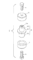
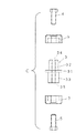
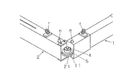
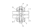
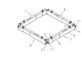
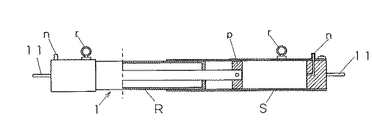
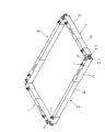
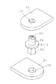
以下、本発明の実施例について図面に基づいて説明する。図1乃至図7は本発明の第1実施例について示したものである。図1は枠体連結具の分解斜視図、図2は同連結具の分解側面図、図3は枠体の端部構造と連結具との連結手段を説明する分解斜視図、図4はフレームどうしの連結状態を示す斜視図、図5は同連結状態を示す側面図、図6はフレームの組み立て状態を示す斜視図、図7はフレームの伸縮構造例を説明するシリンダの要部の縦断面図である。 Embodiments of the present invention will be described below with reference to the drawings. 1 to 7 show a first embodiment of the present invention. FIG. 1 is an exploded perspective view of the frame connector, FIG. 2 is an exploded side view of the connector, FIG. 3 is an exploded perspective view for explaining a connection means between the end structure of the frame and the connector, and FIG. FIG. 5 is a side view showing the connected state, FIG. 6 is a perspective view showing the assembled state of the frame, and FIG. 7 is a longitudinal section of the main part of the cylinder for explaining an example of the frame expansion and contraction structure. FIG.
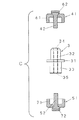
而して、該実施例に示した枠体連結具Cは、図1及び図2に示したように、大別すると金具本体3と連結ネジ4,5との3部材からなっている。該実施例に示した金具本体3は、全体として短尺の円筒体状に形成されていて、その上下方向中間部には同心状とした円形のフランジ部31をフランジ状に形成してあり、このフランジ部31を挟んでその上下に胴部32,33を形成してあり、その内部には全長に亘って雌ねじを貫通形成してあり、その上下両端からボルトを挿入螺合する螺合ネジ34,35としてある。また、前記連結ネジ4,5は、これらの螺合ネジ34,35に螺合する雄ねじとしてある。
Thus, as shown in FIGS. 1 and 2, the frame connector C shown in the embodiment is roughly composed of three members, that is, the
これらの雌ねじとした螺合ネジ34,35は、上下の胴部32,33から上下に突出させた雄ねじとし、連結ネジ4,5を雌ねじとして実施してもよいことは言うまでもない。また、該実施例では、上下の胴部32,33と連結ネジ4,5との間に、それぞれの胴部32,33を覆う形状とした袋ナット6,7を介在させて座金代用としてある。この袋ナット6,7についても通常の円盤座金を使用してもよく、座金付きボルトを使用してもよい。
Needless to say, these threaded
該実施例に示した前記上下の胴部32,33は、下部の胴部33の径に比して上部の胴部32の径を小径とし、その上端部を円錐状に形成してある。このように形成しておくことによって、後述するフレーム1または2の一対をその両端の連結部11または21に形成してある穿孔12または22に、前記金具本体3の上部胴部32を上向きに突出させた状態として金具本体3を連結した状態で、他の一対のフレーム2または1に先行して掘削穴内の所定位置に降下させ、続いて、残る一対のフレーム2または1を降下させて、その両端の穿孔22または12を上部胴部32に嵌合させ、地上からボルトで連結する操作を容易にできるようにするためのものである。この構造は、掘削穴内での作業終了後において、地上からボルトの解除操作をして、連結部11,21が上位のフレーム1または2を個々に地上に引き上げる操作時にも、上部胴部32から容易に外し得るように配慮したものでもある。
The upper and
本実施例の枠体連結具Cは、以上のように形成してあるものであって、これを用いてフレームどうしの連結を行うには、図3に示したように、左右二本のフレーム1,2の端部に一体的に水平方向に向けて突出連設させてある連結部11,21の高位置側の連結部21の穿孔22に対して金具本体3の下部胴部33を挿入し、下方から下部袋ナット7を介して下部連結ネジ5で締め付け連結する。このとき、上部胴部32は上向きに突出しているので、その上方から他方のフレーム1の連結部11を降下させてその穿孔12と胴部32とを嵌合させ、その上方から上部袋ナット6を介して上下部連結ネジ4で締め付け連結する。この連結部の側面形状を図拡大して示すと図5のようになる。
The frame connector C of the present embodiment is formed as described above, and in order to connect the frames using this, as shown in FIG. The
同様の操作を四隅部分で行い図6に示したように、二対4本のフレーム1,1と2,2とを方形状に組み付けて方形状とした土留め用枠体を形成する。該図6に示した土留め用枠体は、二対4本のフレーム1,1と2,2との長さをほぼ同じ長さとしたものを用いて例えばマンホールや浄化槽の埋設に多く用いられる略正方形状の枠体としたものを示してある。
Similar operations are performed at the four corners, and as shown in FIG. 6, two pairs of
而して、本発明にいうところの伸縮自在としたフレーム構造の一例として、流体圧利用シリンダの内部構造を参考までに例示しておくと、図7に示したように、ここに示した伸縮フレーム1は、長手方向の両端近くにワイヤー・ロープ等の係止用吊り下げ環r,rと油圧等の流体圧ホースを接続するノズルn,nとを備え、流体圧をピストンpで受け止めて長さを伸縮する構造としたものである。言うまでもなく、この伸縮手段は油圧等の流体圧を利用したものに限らず、例えば、前記引用文献1に記載のネジ軸の回転による伸縮機構としたものであってもよい。
Thus, as an example of the frame structure that can be expanded and contracted according to the present invention, the internal structure of the fluid pressure utilization cylinder is illustrated for reference, as shown in FIG. The
図8は、前記二対のフレーム1,1、2,2のうち、一対のフレーム1,1の長さと他の一対のフレーム2,2の長さとを異なるものとして、長方形状の枠体を得る場合の枠体を例示したものである。前記図6の枠体並びに該図8の枠体は、二対4本のフレーム1,1と2,2とを何れも伸縮自在構造としたフレームについて示してあるが、例えば水道管やケーブル保護管の埋設に際して形成される掘削溝に使用する場合には、何れか一対のフレームを伸縮しないものとすることができる。
FIG. 8 shows that the length of the pair of
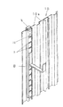
図9及び10は、腹起こしフレームを支持させる腹起こしホルダーの説明図であって、長尺のチャンネル形鋼材の上下方向に所定間隔で複数のブラケット掛止孔hを穿設した腹起こしフレームのホルダーHを形成し、これをその上端に連結固定した下向きコの字形の矢板への掛止用ブラケットbを利用して、先行打設パネル群10の適宜のパネル10aに引っ掛けてパネル群10の内面に沿って垂下させ、予め選択した適宜高さのブラケット掛止孔hに係合させた側面視コの字形のフレーム受けブラケットBを掘削穴内に向けて突出させる。同様にして、所定の間隔を隔てて同じ面のパネル群10にもう一つの腹起こしホルダーHを吊り下げて、フレーム受けブラケットBを突出させる。地上から吊り下げたフレームをこのフレーム受けブラケットB,B上に載せて支持させる。対向する側のパネル群10にも、同様にして二つのブラケットB,Bを突出させ、フレームを吊り下げて載置させる。続いて、これら一対のフレームの両端に突出形成された連結部上に、他の一対のフレームの連結部をそれぞれ載置して、その重合部を地上からの操作でネジ連結し、方形状の枠体を掘削穴内で組み立てる。
FIGS. 9 and 10 are explanatory views of the erection holder for supporting the erection frame, in which the erection frame having a plurality of bracket retaining holes h formed at predetermined intervals in the vertical direction of the long channel steel material. The holder H is formed and hooked to an appropriate panel 10a of the preceding
図11及び12は、前記金具本体3に対して螺嵌する締め付けネジの別実施例を示したもので、該実施例に示した締め付けネジ41,51は実質的に同じもので、前記第1実施例として記載した袋ナット6,7に相当する袋状としたナット61,71を合成樹脂の成形品とし、その成形時に金属ボルト42,52をインサート成形したものである。このネジ41,51は、図12に示したように、上部に突出させた頭部62,72を六角ナット状とし、袋ナット61,71部分も角形レンチで弛緩操作ができるように四角ナット状に成形したものである。
FIGS. 11 and 12 show another embodiment of a tightening screw that is screwed into the metal
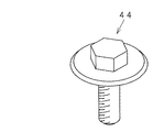
また、図13及び図14は、それぞれ別構造としたの締め付けネジを示したもので、図1の締め付けネジ43は、前記第1実施例に示した連結ネジ4を、頭部下部分に小径部4aを形成してあるものとし、袋ナット6の内奥部において容易には落下しない程度に円盤ワッシャ6aを嵌合させて、連結ネジ4と袋ナット6を不分離状態としたものである。図14の締め付けネジ44は、前記第1実施例に示した連結ネジ4を、連結ネジ部分と座金部分とを一体としたワッシャ付きボルトとしたものである。連結ネジとしてはこのようなボルトも使用することができる。
FIGS. 13 and 14 show a fastening screw having a different structure, and the
図15及び図16は、それぞれ連結具の別実施例を示したもので、図15の連結具は、前記第1実施例に示した連結具における金具本体3の下部胴部33のみを角柱形とし、この下部胴部33と嵌合する下方側の連結部21の穿孔22も角孔とし、下部胴部33の周り止め作用をさせ、上部胴部32に対する連結ネジ4の締結及び弛緩時における金具本体3の共周りを回避させるようにしたものである。図16に示した連結具は、上下の胴部32,33を角柱形とし、フレームの連結部11,21に形成してある穿孔12,22の形状もそれぞれに嵌合する角孔としたものである。但し、上部の角孔と上部胴部32の角柱との間には、軸周方向に小許のクリアランスのあるものとしておき、フレーム1,2の伸縮操作の妨げとならないように配慮しておくのが好ましい。
FIGS. 15 and 16 show other embodiments of the connector, respectively. In the connector of FIG. 15, only the
以上本発明の実施例について説明したが、本発明は、これらの実施例に示した構造のみに限定されるものではなく、前記の構成要件を備え、前記の目的を達成し、前記の効果を備えている範囲内において、適宜に変更実施することができるものである。 Although the embodiments of the present invention have been described above, the present invention is not limited only to the structures shown in these embodiments, and includes the above-described configuration requirements, achieves the above-described object, and achieves the above-described effects. Modifications can be made as appropriate within the range provided.
本発明は、以上のように土留め用フレームを極めて容易に組み立て解体できるものであって、各フレームを地上において組み立てるだけでなく、各フレームを個々に掘削穴内に吊り下げて、地上からの操作で掘削穴内で組み立てることもでき、所要品の埋設後は掘削穴内に入ることなく、地上からの操作で解体作業も行うことができるので、この種の工事において大いに利用されるものと期待される。 As described above, the present invention can assemble and dismantle the retaining frame very easily. In addition to assembling each frame on the ground, each frame is individually suspended in the excavation hole to operate from the ground. Can be assembled in the excavation hole, and after embedding the required products, it can be dismantled from the ground without entering the excavation hole, so it is expected to be used greatly in this kind of construction .
1 フレーム
10 パネル群
10a パネル
11 連結部
12 穿孔
2 フレーム
21 連結部
22 穿孔
3 金具本体
31 フランジ部
32 上部胴部
33 下部胴部
34 螺合ネジ
35 螺合ネジ
4 連結ネジ
5 連結ネジ
6 袋ナット
7 袋ナット
C 連結具
n エアーノズル
r 吊り下げリング
DESCRIPTION OF
Claims (2)
前記各フレーム(1,2)が、長手方向両端部に上下方向に開口する穿孔(12,22)を有する連結部(11,21)を備え、
前記連結具(C)が、上下方向中間部のフランジ部(31)を挟んでその上下に前記穿孔(12,22)と嵌合する胴部(32,33)を備え、その上下両端部に螺合ネジ(34,35)を有する金具本体(3)と、
前記螺合ネジ(34,35)とそれぞれ螺合する連結ネジ(4,5)とによって構成されている土留め用枠体連結具。
It is arranged on the inner surface of the panel group (10) erected on the two opposing or four rectangular faces of the excavation hole that has dug down the ground, and is used to maintain the spacing between the panel groups (10, 10). A connecting tool (C) for assembling and connecting two pairs of four frames (1, 1) (2, 2) including at least a pair of length-adjustable frames,
Each of the frames (1, 2) includes a connecting portion (11, 21) having perforations (12, 22) opening in the vertical direction at both ends in the longitudinal direction,
The connector (C) includes a body portion (32, 33) fitted to the perforation (12, 22) above and below the flange portion (31) of the intermediate portion in the vertical direction, and at both upper and lower end portions thereof. A metal fitting body (3) having threaded screws (34, 35);
A retaining frame frame connector comprising the screw screws (34, 35) and the connecting screws (4, 5) screwed together.
各フレーム(1,2)が、長手方向両端部に上下方向に開口する穿孔(12,22)を有する連結部(11,21)を備えていて、
別途形成された土留め用枠体連結具(C)の金具本体(3)における、上下方向中間部に形成されたフランジ部(31)の上下に連設された上部胴部(32)と下部胴部(33)とが、前記穿孔(12,22)に嵌め込まれ、これら胴部(32,33)の上下端に形成されたそれぞれの螺合ネジ(34,35)に螺合された連結ネジ(4,5)によって、前記連結部(11,21)が前記フランジ部(31)をスペーサーとして上下方向に締結され、
前記4本のフレームが方形状に組み付けられている土留め用枠体。 A method for maintaining the space between the panel groups (10, 10), which is arranged on the inner surface of the panel group (10) standing upright on the two facing or four rectangular faces of the excavation hole dug down the ground A frame composed of two pairs of four frames (1, 1) (2, 2) including at least a pair of frames whose lengths are adjustable, which are assembled and connected in a shape;
Each frame (1, 2) includes a connecting portion (11, 21) having perforations (12, 22) opening in the vertical direction at both ends in the longitudinal direction,
The upper body part (32) and the lower part connected to the upper and lower sides of the flange part (31) formed in the intermediate part in the vertical direction in the metal fitting body (3) of the separately formed earth retaining frame connector (C) The body part (33) is fitted into the perforations (12, 22) and is connected to the respective threaded screws (34, 35) formed on the upper and lower ends of the body part (32, 33). By means of screws (4, 5), the connecting part (11, 21) is fastened in the vertical direction with the flange part (31) as a spacer,
The earth retaining frame in which the four frames are assembled in a square shape.
Priority Applications (1)
| Application Number | Priority Date | Filing Date | Title |
|---|---|---|---|
| JP2007268531A JP4954840B2 (en) | 2007-10-16 | 2007-10-16 | Earth retaining frame connector and earth retaining frame |
Applications Claiming Priority (1)
| Application Number | Priority Date | Filing Date | Title |
|---|---|---|---|
| JP2007268531A JP4954840B2 (en) | 2007-10-16 | 2007-10-16 | Earth retaining frame connector and earth retaining frame |
Publications (2)
| Publication Number | Publication Date |
|---|---|
| JP2009097204A true JP2009097204A (en) | 2009-05-07 |
| JP4954840B2 JP4954840B2 (en) | 2012-06-20 |
Family
ID=40700472
Family Applications (1)
| Application Number | Title | Priority Date | Filing Date |
|---|---|---|---|
| JP2007268531A Active JP4954840B2 (en) | 2007-10-16 | 2007-10-16 | Earth retaining frame connector and earth retaining frame |
Country Status (1)
| Country | Link |
|---|---|
| JP (1) | JP4954840B2 (en) |
Citations (2)
| Publication number | Priority date | Publication date | Assignee | Title |
|---|---|---|---|---|
| JPS6149802A (en) * | 1984-08-20 | 1986-03-11 | 松下電工株式会社 | Cement molding press device |
| JP2001049666A (en) * | 1999-08-06 | 2001-02-20 | Shinkoo Corporation:Kk | Temporary earth retaining device for manholes |
-
2007
- 2007-10-16 JP JP2007268531A patent/JP4954840B2/en active Active
Patent Citations (2)
| Publication number | Priority date | Publication date | Assignee | Title |
|---|---|---|---|---|
| JPS6149802A (en) * | 1984-08-20 | 1986-03-11 | 松下電工株式会社 | Cement molding press device |
| JP2001049666A (en) * | 1999-08-06 | 2001-02-20 | Shinkoo Corporation:Kk | Temporary earth retaining device for manholes |
Also Published As
| Publication number | Publication date |
|---|---|
| JP4954840B2 (en) | 2012-06-20 |
Similar Documents
| Publication | Publication Date | Title |
|---|---|---|
| JP5479042B2 (en) | Liner plate connection structure and liner plate connection structure | |
| US20120308308A1 (en) | Foundation support installer | |
| KR102036588B1 (en) | Underground line support for checking leak | |
| US8926229B1 (en) | Trench box dewatering system | |
| US20110318116A1 (en) | Modular vertical shoring system with cylindrical interconnected sleeves | |
| JP4954840B2 (en) | Earth retaining frame connector and earth retaining frame | |
| JP2969151B2 (en) | Temporary frame type for earth retaining | |
| CN212612474U (en) | A cast-in-place pile reinforcement cage assembly | |
| CN210887239U (en) | Municipal administration pipeline slot supporting construction | |
| JP6068774B1 (en) | Earth retaining prior construction method using adjustable erection | |
| CN107119694A (en) | The method of construction of the deep basal pit auxiliary support apparatus of anti-pipe network deformation under urban environment | |
| JP6513470B2 (en) | Foundation pile for installation, foundation pile for installation of solar panels, installation method of foundation pile and installation method of foundation pile for solar panels | |
| JP3183635U (en) | Square frame for earth retaining | |
| CN110629765B (en) | Safety protection device and protection method for H-shaped steel foundation pit | |
| KR100714434B1 (en) | Bracing for Bracing | |
| EP3792431A2 (en) | Hoarding post mounting apparatus and method | |
| KR100930001B1 (en) | Earth pressure support brace device for water and sewage maintenance and construction method | |
| WO2018119393A1 (en) | Apparatus and method for installing a manhole chimney liner | |
| KR100871895B1 (en) | Bracing for horizontal and vertical and center brace reinforcement | |
| KR102178790B1 (en) | Supporting structure for concrete wall | |
| JP2835571B2 (en) | Earth retaining sheet pile support method | |
| KR102731081B1 (en) | H-beam installation device for construction of retaining wall | |
| JP2000134779A (en) | Lightweight unit tube | |
| JP6344753B2 (en) | Underground structure and its construction method | |
| JP2001182026A (en) | Security enclosure |
Legal Events
| Date | Code | Title | Description |
|---|---|---|---|
| RD04 | Notification of resignation of power of attorney |
Free format text: JAPANESE INTERMEDIATE CODE: A7424 Effective date: 20090625 |
|
| A621 | Written request for application examination |
Free format text: JAPANESE INTERMEDIATE CODE: A621 Effective date: 20091218 |
|
| A977 | Report on retrieval |
Free format text: JAPANESE INTERMEDIATE CODE: A971007 Effective date: 20110621 |
|
| TRDD | Decision of grant or rejection written | ||
| A01 | Written decision to grant a patent or to grant a registration (utility model) |
Free format text: JAPANESE INTERMEDIATE CODE: A01 Effective date: 20120228 |
|
| A01 | Written decision to grant a patent or to grant a registration (utility model) |
Free format text: JAPANESE INTERMEDIATE CODE: A01 |
|
| A61 | First payment of annual fees (during grant procedure) |
Free format text: JAPANESE INTERMEDIATE CODE: A61 Effective date: 20120314 |
|
| R150 | Certificate of patent or registration of utility model |
Ref document number: 4954840 Country of ref document: JP Free format text: JAPANESE INTERMEDIATE CODE: R150 Free format text: JAPANESE INTERMEDIATE CODE: R150 |
|
| FPAY | Renewal fee payment (event date is renewal date of database) |
Free format text: PAYMENT UNTIL: 20150323 Year of fee payment: 3 |
|
| R250 | Receipt of annual fees |
Free format text: JAPANESE INTERMEDIATE CODE: R250 |
|
| R250 | Receipt of annual fees |
Free format text: JAPANESE INTERMEDIATE CODE: R250 |
|
| R250 | Receipt of annual fees |
Free format text: JAPANESE INTERMEDIATE CODE: R250 |
|
| R250 | Receipt of annual fees |
Free format text: JAPANESE INTERMEDIATE CODE: R250 |
|
| R250 | Receipt of annual fees |
Free format text: JAPANESE INTERMEDIATE CODE: R250 |
|
| R250 | Receipt of annual fees |
Free format text: JAPANESE INTERMEDIATE CODE: R250 |
|
| R250 | Receipt of annual fees |
Free format text: JAPANESE INTERMEDIATE CODE: R250 |
|
| R250 | Receipt of annual fees |
Free format text: JAPANESE INTERMEDIATE CODE: R250 |
|
| R250 | Receipt of annual fees |
Free format text: JAPANESE INTERMEDIATE CODE: R250 |
|
| R250 | Receipt of annual fees |
Free format text: JAPANESE INTERMEDIATE CODE: R250 |
|
| R250 | Receipt of annual fees |
Free format text: JAPANESE INTERMEDIATE CODE: R250 |
|
| R250 | Receipt of annual fees |
Free format text: JAPANESE INTERMEDIATE CODE: R250 |