JP2009097739A - 管寄せの支持構造 - Google Patents
管寄せの支持構造 Download PDFInfo
- Publication number
- JP2009097739A JP2009097739A JP2007267434A JP2007267434A JP2009097739A JP 2009097739 A JP2009097739 A JP 2009097739A JP 2007267434 A JP2007267434 A JP 2007267434A JP 2007267434 A JP2007267434 A JP 2007267434A JP 2009097739 A JP2009097739 A JP 2009097739A
- Authority
- JP
- Japan
- Prior art keywords
- header
- heat transfer
- support
- transfer tube
- tube group
- Prior art date
- Legal status (The legal status is an assumption and is not a legal conclusion. Google has not performed a legal analysis and makes no representation as to the accuracy of the status listed.)
- Granted
Links
Images




Landscapes
- Heat-Exchange Devices With Radiators And Conduit Assemblies (AREA)
Abstract
【解決手段】ボイラ火炉の下流側排ガス流路に設置される横置きの伝熱管群22が接続される管寄せ1の上面に内部流体流路が連通した、ほぼ鉛直方向に伸びる複数の管寄せ支持管2を接続し、支持管2を天井壁伝熱面4を貫通して、その上方で横方向に折り曲げて上部管寄せ8に接続し、前記折り曲げ部位でスリングロッド5を介してその上方の鉄骨6に吊下げたボイラ火炉内管寄せの支持構造である。
【選択図】図1
Description
一方、管寄せ1aについては、トラスサポート15で支持できないため、火炉側壁で両端部を支えるほか、別の手段で支持する必要がある。
たとえば、特許文献1記載の発明では、後部伝熱部炉壁(前壁、中間壁、(後壁は不明))に伝熱管ごとに多数のブラケットを設けて支持する方式であり、これらの管寄せを支持するため部材の設置が必要である。
請求項1記載の発明は、ボイラ火炉の下流側排ガス流路に設置され、横置き(水平置き)の伝熱管群(22)が接続される管寄せ(1)の支持構造であって、該管寄せ(1)の上面に内部流体流路が連通した、ほぼ鉛直方向に伸びる複数の管寄せ支持管(2)が接続され、該管寄せ支持管(2)は天井壁伝熱面(4)を貫通して、その上方で横(水平)方向に折り曲げられ、当該折り曲げ部位でスリングロッド(5)を介してその上方の鉄骨(6)から吊下げられている管寄せの支持構造である。
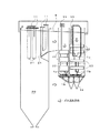
上側のパネル状の伝熱管群22と下側のパネル状の伝熱管群23に挟まれた部位に配置された下部管寄せ1aは、図6に示すように炉外に配置換えして炉外において非冷却部材のスリングロッド5で支持する方法、または図7に示すように下部管寄せ1aを炉内に配置したまま、下部管寄せ1bにつながる伝熱管群23をサポートする管群支持管3と同じ流体の経路を有する伝熱管からなる管寄せ支持管2によって下部管寄せ1aの荷重を支持する構造である。なお、図7の伝熱管群支持管3などの配管の上部管寄せ付近の円B内を拡大図で示す
図8は図7に示す従来の管寄せ支持構造のA部拡大図を示す。上側の伝熱管群22と下側の伝熱管群23に挟まれた配置の管寄せ1aは、管寄せ1a、1bの支持管2へ溶接接合した非冷却部材で構成されたサポート金具17を用いて荷重を支持される。
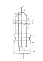
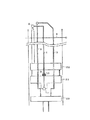
図1は、本発明の実施例1に係わる管寄せ支持構造の側面図であり、図2は実施例1の管寄せ支持構造を補足説明する鳥瞰図である。
この管寄せ支持管2は天井壁管4を貫通して上方に伸びた後、上部管寄せ8に接続されるが、下部管寄せ1aの重量を支持するため、天井壁4を越えた鉛直部において非冷却部材であるスリングロッド5を接続し、スリングロッド5は上部の鉄骨6と連結される。
実施例1と異なる点は、下部管寄せ1aに接続された伝熱管群22で構成される複数のパネルのうちの最下流部の伝熱管群22の水平部に、例えば、一対のC型鋼である支持部材10を管寄せ支持管2を挟み込むよう背中合わせに配置し、管寄せ支持管2に取付けた小片のラグ9と伝熱管群22により支持部材10を挟み込む構造である。
3 管群支持管 4 天井壁
5 スリングロッド 6 鉄骨
7 スプリングハンガ 8 上部管寄せ
9 ラグ 10 支持部材
11 吊下げ伝熱管上部管寄せ 14 灰貯めケーシング
15 トラスサポート 17 サポート金具
20 火炉 21,22,23 伝熱管群
Claims (2)
- ボイラ火炉の下流側排ガス流路に設置され、水平置きの伝熱管群(22)が接続される管寄せ(1)の支持構造であって、
該管寄せ(1)の上面に内部流体流路が連通した、ほぼ鉛直方向に伸びる複数の管寄せ支持管(2)が接続され、該管寄せ支持管(2)は天井壁伝熱面(4)を貫通して、その上方で水平方向に折り曲げられ、当該折り曲げ部位でスリングロッド(5)を介してその上方の鉄骨(6)から吊下げられていることを特徴とする管寄せの支持構造。 - 前記管寄せ支持管(2)は、火炉外部に設けられ、前記水平置きの伝熱管群(22)が接続される上部管寄せ(8)に接続されていることを特徴とする請求項1に記載の管寄せの支持構造。
Priority Applications (1)
| Application Number | Priority Date | Filing Date | Title |
|---|---|---|---|
| JP2007267434A JP5160180B2 (ja) | 2007-10-15 | 2007-10-15 | 管寄せの支持構造 |
Applications Claiming Priority (1)
| Application Number | Priority Date | Filing Date | Title |
|---|---|---|---|
| JP2007267434A JP5160180B2 (ja) | 2007-10-15 | 2007-10-15 | 管寄せの支持構造 |
Publications (2)
| Publication Number | Publication Date |
|---|---|
| JP2009097739A true JP2009097739A (ja) | 2009-05-07 |
| JP5160180B2 JP5160180B2 (ja) | 2013-03-13 |
Family
ID=40700915
Family Applications (1)
| Application Number | Title | Priority Date | Filing Date |
|---|---|---|---|
| JP2007267434A Active JP5160180B2 (ja) | 2007-10-15 | 2007-10-15 | 管寄せの支持構造 |
Country Status (1)
| Country | Link |
|---|---|
| JP (1) | JP5160180B2 (ja) |
Cited By (2)
| Publication number | Priority date | Publication date | Assignee | Title |
|---|---|---|---|---|
| CN103017136A (zh) * | 2012-12-26 | 2013-04-03 | 哈尔滨锅炉厂有限责任公司 | 锅炉桁架中支撑管与支撑管之间优化连接装置 |
| CN111594820A (zh) * | 2020-06-01 | 2020-08-28 | 哈尔滨锅炉厂有限责任公司 | 一种用于降低管屏流量偏差的集箱结构 |
Families Citing this family (1)
| Publication number | Priority date | Publication date | Assignee | Title |
|---|---|---|---|---|
| CN110822407B (zh) * | 2019-11-26 | 2021-08-20 | 哈尔滨锅炉厂有限责任公司 | 新型省煤器烟道结构及安装布置方法 |
Citations (2)
| Publication number | Priority date | Publication date | Assignee | Title |
|---|---|---|---|---|
| JPS63134202U (ja) * | 1987-02-19 | 1988-09-02 | ||
| JPH09229302A (ja) * | 1996-02-26 | 1997-09-05 | Ishikawajima Harima Heavy Ind Co Ltd | ボイラ後伝部構造 |
-
2007
- 2007-10-15 JP JP2007267434A patent/JP5160180B2/ja active Active
Patent Citations (2)
| Publication number | Priority date | Publication date | Assignee | Title |
|---|---|---|---|---|
| JPS63134202U (ja) * | 1987-02-19 | 1988-09-02 | ||
| JPH09229302A (ja) * | 1996-02-26 | 1997-09-05 | Ishikawajima Harima Heavy Ind Co Ltd | ボイラ後伝部構造 |
Cited By (4)
| Publication number | Priority date | Publication date | Assignee | Title |
|---|---|---|---|---|
| CN103017136A (zh) * | 2012-12-26 | 2013-04-03 | 哈尔滨锅炉厂有限责任公司 | 锅炉桁架中支撑管与支撑管之间优化连接装置 |
| CN103017136B (zh) * | 2012-12-26 | 2016-06-08 | 哈尔滨锅炉厂有限责任公司 | 锅炉桁架中支撑管与支撑管之间优化连接装置 |
| CN111594820A (zh) * | 2020-06-01 | 2020-08-28 | 哈尔滨锅炉厂有限责任公司 | 一种用于降低管屏流量偏差的集箱结构 |
| CN111594820B (zh) * | 2020-06-01 | 2022-02-08 | 哈尔滨锅炉厂有限责任公司 | 一种用于降低管屏流量偏差的集箱结构 |
Also Published As
| Publication number | Publication date |
|---|---|
| JP5160180B2 (ja) | 2013-03-13 |
Similar Documents
| Publication | Publication Date | Title |
|---|---|---|
| CN203940411U (zh) | 一种对流过热器的布置结构 | |
| CN101788140B (zh) | 一种用于蛇形管屏的悬吊管悬吊结构 | |
| JP5160180B2 (ja) | 管寄せの支持構造 | |
| CN204084298U (zh) | 废热锅炉 | |
| RU2364785C2 (ru) | Подвесной паровой котел | |
| FI124375B (fi) | Lämpövoimakattilalaitos | |
| CN201662049U (zh) | 一种蛇形管排支吊结构 | |
| CN205102103U (zh) | 应用于锅炉的过热器 | |
| PL225405B1 (pl) | Duża wytwornica pary | |
| CN105222122B (zh) | 应用于锅炉的过热器 | |
| JP5611678B2 (ja) | ボイラ装置 | |
| CN201662050U (zh) | 一种蛇形管排悬吊结构 | |
| CN223579900U (zh) | 一种蛇形管过热器的支撑装置 | |
| CN222503832U (zh) | 一种循环流化床锅炉 | |
| JP2009228985A (ja) | ボイラ装置 | |
| CN219755545U (zh) | 一种多水管组合侧向抗震支架 | |
| JP3737186B2 (ja) | 排熱回収装置 | |
| JP2001317893A (ja) | ガスショートパス防止バッフル | |
| JP2015096800A (ja) | 内部で補強された高寿命な排熱回収ボイラ装置 | |
| CN116438406B (zh) | 废热回收锅炉的支撑机构 | |
| JP4410433B2 (ja) | ボイラの支持構造体 | |
| JP2001012878A (ja) | 熱交換器 | |
| JP5931599B2 (ja) | 舶用ボイラ構造、船舶及び舶用ボイラの過熱器ヘッダ支持方法 | |
| CN116576477A (zh) | 一种支撑省煤器的烟道结构 | |
| JP4301697B2 (ja) | ボイラ |
Legal Events
| Date | Code | Title | Description |
|---|---|---|---|
| A621 | Written request for application examination |
Free format text: JAPANESE INTERMEDIATE CODE: A621 Effective date: 20100917 |
|
| A977 | Report on retrieval |
Free format text: JAPANESE INTERMEDIATE CODE: A971007 Effective date: 20120531 |
|
| A131 | Notification of reasons for refusal |
Free format text: JAPANESE INTERMEDIATE CODE: A131 Effective date: 20120612 |
|
| A521 | Written amendment |
Free format text: JAPANESE INTERMEDIATE CODE: A523 Effective date: 20120806 |
|
| TRDD | Decision of grant or rejection written | ||
| A01 | Written decision to grant a patent or to grant a registration (utility model) |
Free format text: JAPANESE INTERMEDIATE CODE: A01 Effective date: 20121211 |
|
| A61 | First payment of annual fees (during grant procedure) |
Free format text: JAPANESE INTERMEDIATE CODE: A61 Effective date: 20121212 |
|
| R150 | Certificate of patent or registration of utility model |
Ref document number: 5160180 Country of ref document: JP Free format text: JAPANESE INTERMEDIATE CODE: R150 Free format text: JAPANESE INTERMEDIATE CODE: R150 |
|
| FPAY | Renewal fee payment (event date is renewal date of database) |
Free format text: PAYMENT UNTIL: 20151221 Year of fee payment: 3 |
|
| S111 | Request for change of ownership or part of ownership |
Free format text: JAPANESE INTERMEDIATE CODE: R313111 |
|
| R350 | Written notification of registration of transfer |
Free format text: JAPANESE INTERMEDIATE CODE: R350 |
|
| S533 | Written request for registration of change of name |
Free format text: JAPANESE INTERMEDIATE CODE: R313533 |
|
| R350 | Written notification of registration of transfer |
Free format text: JAPANESE INTERMEDIATE CODE: R350 |