JP2009104902A - Method for producing non-aqueous electrolyte secondary battery - Google Patents
Method for producing non-aqueous electrolyte secondary battery Download PDFInfo
- Publication number
- JP2009104902A JP2009104902A JP2007275763A JP2007275763A JP2009104902A JP 2009104902 A JP2009104902 A JP 2009104902A JP 2007275763 A JP2007275763 A JP 2007275763A JP 2007275763 A JP2007275763 A JP 2007275763A JP 2009104902 A JP2009104902 A JP 2009104902A
- Authority
- JP
- Japan
- Prior art keywords
- battery
- charging
- wound body
- secondary battery
- aqueous electrolyte
- Prior art date
- Legal status (The legal status is an assumption and is not a legal conclusion. Google has not performed a legal analysis and makes no representation as to the accuracy of the status listed.)
- Withdrawn
Links
Images


Classifications
-
- Y—GENERAL TAGGING OF NEW TECHNOLOGICAL DEVELOPMENTS; GENERAL TAGGING OF CROSS-SECTIONAL TECHNOLOGIES SPANNING OVER SEVERAL SECTIONS OF THE IPC; TECHNICAL SUBJECTS COVERED BY FORMER USPC CROSS-REFERENCE ART COLLECTIONS [XRACs] AND DIGESTS
- Y02—TECHNOLOGIES OR APPLICATIONS FOR MITIGATION OR ADAPTATION AGAINST CLIMATE CHANGE
- Y02E—REDUCTION OF GREENHOUSE GAS [GHG] EMISSIONS, RELATED TO ENERGY GENERATION, TRANSMISSION OR DISTRIBUTION
- Y02E60/00—Enabling technologies; Technologies with a potential or indirect contribution to GHG emissions mitigation
- Y02E60/10—Energy storage using batteries
-
- Y—GENERAL TAGGING OF NEW TECHNOLOGICAL DEVELOPMENTS; GENERAL TAGGING OF CROSS-SECTIONAL TECHNOLOGIES SPANNING OVER SEVERAL SECTIONS OF THE IPC; TECHNICAL SUBJECTS COVERED BY FORMER USPC CROSS-REFERENCE ART COLLECTIONS [XRACs] AND DIGESTS
- Y02—TECHNOLOGIES OR APPLICATIONS FOR MITIGATION OR ADAPTATION AGAINST CLIMATE CHANGE
- Y02P—CLIMATE CHANGE MITIGATION TECHNOLOGIES IN THE PRODUCTION OR PROCESSING OF GOODS
- Y02P70/00—Climate change mitigation technologies in the production process for final industrial or consumer products
- Y02P70/50—Manufacturing or production processes characterised by the final manufactured product
Landscapes
- Secondary Cells (AREA)
- Battery Electrode And Active Subsutance (AREA)
Abstract
【課題】通常使用時の充放電に起因する電池の膨張を低レベルに抑えることが可能な非水電解液二次電池の製造方法を提供すること。
【解決手段】正極及び負極並びにこれらの間に介在配置されたセパレータが一体に捲回されてなる捲回体10を電池缶12内に装填し、次いで充電を行う工程を有する非水電解液二次電池の製造方法である。充電に起因する捲回体10の膨張体積に見合った分の余剰スペースを有する電池缶12内に、捲回体10を装填する。次いで捲回体10の膨張に起因する電池缶12の変形を規制した状態下に充電を行う。
【選択図】図2To provide a method for producing a non-aqueous electrolyte secondary battery capable of suppressing the expansion of a battery due to charge / discharge during normal use to a low level.
A non-aqueous electrolyte solution comprising a step of charging a battery can in which a wound body is formed by integrally winding a positive electrode, a negative electrode, and a separator interposed therebetween, and then charging the battery. This is a method for manufacturing a secondary battery. The wound body 10 is loaded into the battery can 12 having an excess space corresponding to the expansion volume of the wound body 10 caused by charging. Next, charging is performed in a state where the deformation of the battery can 12 due to the expansion of the wound body 10 is restricted.
[Selection] Figure 2
Description
本発明は、リチウム二次電池などの非水電解液二次電池の製造方法に関する。 The present invention relates to a method for producing a non-aqueous electrolyte secondary battery such as a lithium secondary battery.
リチウム二次電池などの非水電解液二次電池においては、電池の充放電によって電池内部で発生したガスや、充電時の電極の膨張に起因して内圧が上昇し、それによって厚みの増加等の電池の変形が発生することがある。電池の変形はエネルギー密度の低下の原因となる。この傾向は、円筒型の電池に比べ、圧力変形を受けやすい形状を有している角型の電池で顕著である。更に、角型電池の扁平部においては、発生したガスの残存やガスによる膨れのために、正負極間に未反応部分が生じ、これが容量低下の原因になったり、正負極間の距離が大きくなることに起因して均一な電極反応が阻害されたりすることがある。 In non-aqueous electrolyte secondary batteries such as lithium secondary batteries, internal pressure increases due to gas generated inside the battery due to battery charging and discharging, and expansion of the electrode during charging, thereby increasing thickness, etc. The battery may be deformed. The deformation of the battery causes the energy density to decrease. This tendency is conspicuous in a rectangular battery having a shape that is susceptible to pressure deformation as compared with a cylindrical battery. Furthermore, in the flat part of the square battery, an unreacted part is generated between the positive and negative electrodes due to the remaining of the generated gas and the swelling due to the gas, which may cause a decrease in capacity or increase the distance between the positive and negative electrodes. As a result, the uniform electrode reaction may be hindered.
上述の問題を解決することを目的として、特許文献1においては、正極、負極及びセパレータからなる扁平型の捲回群と非水電解液とを角型電池ケースに挿入し、密閉して組み立て、充電して仕上げる工程において、充電中又は充電後の充電状態で、角型電池ケースの最大幅広面中央部を加圧する非水電解液二次電池の製造方法が記載されている。この方法では、例えば終止電圧4.07Vまで充電し、次いで電池ケースにおける12mm×40mmの範囲の扁平部に120kgfの圧力を加え、電池ケースをその加圧前の97%の厚みにしている。 In order to solve the above-mentioned problem, in Patent Document 1, a flat wound group consisting of a positive electrode, a negative electrode and a separator and a nonaqueous electrolyte solution are inserted into a rectangular battery case, sealed and assembled, In the step of charging and finishing, a method for manufacturing a non-aqueous electrolyte secondary battery is described in which the central part of the maximum wide surface of the prismatic battery case is pressurized during or after charging. In this method, for example, the battery is charged to a final voltage of 4.07 V, and then a pressure of 120 kgf is applied to a flat portion in a range of 12 mm × 40 mm in the battery case to make the battery case 97% thick before pressurization.
上述の製造方法は、充電に起因する体積膨張の程度が低いグラファイト系の負極活物質を用いた場合には、ある程度有効なものである。しかし、体積膨張の程度が大きい活物質であるシリコン系又はスズ系の材料を用いた場合には、ほとんど効果がないことが、本発明者らの検討の結果判明した。また、充電された状態の電池に120kgfという高圧を加えることは、製造工程上、大きな危険を伴う可能性がある。 The above-described manufacturing method is effective to some extent when a graphite-based negative electrode active material having a low degree of volume expansion resulting from charging is used. However, as a result of examination by the present inventors, it has been found that there is almost no effect when a silicon-based or tin-based material that is an active material having a large volume expansion is used. In addition, applying a high pressure of 120 kgf to a charged battery may be very dangerous in the manufacturing process.
したがって本発明の目的は、前述した従来技術が有する欠点を解消し得る非水電解液二次電池の製造方法を提供することにある。 Accordingly, an object of the present invention is to provide a method for manufacturing a non-aqueous electrolyte secondary battery that can eliminate the above-mentioned drawbacks of the prior art.
本発明は、リチウムイオンを可逆的に吸蔵・放出し得る活物質を含む正極及び負極並びにこれらの間に介在配置されたセパレータが一体に捲回されてなる捲回体を電池缶内に装填し、次いで充電を行う工程を有する非水電解液二次電池の製造方法において、
充電に起因する捲回体の膨張体積に見合った分の余剰スペースを有する電池缶内に該捲回体を装填し、
次いで該捲回体の膨張に起因する電池缶の変形を規制した状態下に充電を行うことを特徴とする非水電解液二次電池の製造方法を提供するものである。
The present invention includes a positive electrode and a negative electrode containing an active material capable of reversibly occluding and releasing lithium ions, and a wound body in which a separator interposed therebetween is integrally wound in a battery can. Then, in the method for producing a non-aqueous electrolyte secondary battery having a step of charging next,
The winding body is loaded into a battery can having a surplus space corresponding to the expansion volume of the winding body due to charging,
Next, the present invention provides a method for producing a non-aqueous electrolyte secondary battery, wherein charging is performed in a state where deformation of the battery can due to expansion of the wound body is regulated.
本発明によれば、通常使用時の充放電に起因する電池の膨張を極めて低いレベルに抑えることが可能になる。 According to the present invention, it is possible to suppress the expansion of the battery due to charging / discharging during normal use to an extremely low level.
以下本発明を、その好ましい実施形態に基づき図面を参照しながら説明する。本実施形態は、角型の非水電解液二次電池の製造方法に係るものである。図1及び図2には、本発明の製造方法の第1の実施形態が模式的に示されている。本実施形態においては、先ず、電池を構成する各部材を重ね合わせ、これらを一体に捲回してなる捲回体10を準備する。捲回体10を構成する部材は、正極、負極及びセパレータである。これらはそれぞれ長尺帯状の形状を有している。
The present invention will be described below based on preferred embodiments with reference to the drawings. The present embodiment relates to a method for manufacturing a rectangular nonaqueous electrolyte secondary battery. 1 and 2 schematically show a first embodiment of the manufacturing method of the present invention. In the present embodiment, first, a
正極は、集電体の各面に、リチウムイオンの吸蔵放出が可能な正極活物質を含む活物質層が形成されてなるものである。一方、負極は、集電体の各面に、リチウムイオンの吸蔵放出が可能な負極活物質を含む活物質層が形成されてなるものである。セパレータは、非水電解液の透過が可能な透液性の多孔質材料からなるものである。 The positive electrode is formed by forming an active material layer containing a positive electrode active material capable of occluding and releasing lithium ions on each surface of a current collector. On the other hand, the negative electrode is formed by forming an active material layer containing a negative electrode active material capable of occluding and releasing lithium ions on each surface of a current collector. The separator is made of a liquid-permeable porous material that can permeate a non-aqueous electrolyte.
捲回体10は、正極と、第1のセパレータと、負極と、第2のセパレータとをこの順で重ね合わせ、これらを一体に捲回することで製造される。捲回の方向は、正極が内側になる方向でもよく、第2のセパレータが内側になる方向でもよい。あるいは捲回体10は、負極と、第1のセパレータと、正極と、第2のセパレータとをこの順で重ね合わせ、これらを一体に捲回することで製造される。捲回の方向は、負極が内側になる方向でもよく、第2のセパレータが内側になる方向でもよい。何れの場合であっても、正極及び負極の集電体には、電流の取り出し用のタブ11,11がそれぞれ取り付けられる。
The
捲回体10は扁平体からなる。このような形状の捲回体10は、上述の各部材を用いて円柱状の捲回体を製造した後に、該捲回体をその軸方向と直交する方向から加圧して扁平に変形させることで得ることができる。あるいは、平板状の巻芯を用い、この巻芯のまわりに上述の各部材を一体的に捲回することで、直接に扁平な捲回体10を得ることができる。この場合、巻芯は、捲回後に引き抜いてもよく、あるいは引き抜かずそのまま捲回体内に保持されてもよい。
The
このようにして得られた捲回体10を電池缶12内に装填する。捲回体10の装填前に、電池缶12の底部にインシュレータ(図示せず)を配置しておく。捲回体10の装填の前後又は装填と同時に、電池缶12内に非水電解液を注入する。電池缶12は、上部が開口した有底の扁平な角筒状の形状をしている。つまり、この電池缶12は角型電池缶である。電池缶12には、相対向する2つの最大幅広面12a,12aを有している。最大幅広面12aは一般に平坦面である。電池缶12は、例えばAl−Mn合金、Al−Mn−Mg合金、内面がニッケルめっきされた鋼板などから構成される。
The
本実施形態の製造方法は、電池缶12の内容積と、捲回体10の体積との関係に特徴の一つを有する。詳細には、電池缶12は、捲回体10の体積分の容積に加えて、充電に起因する捲回体10の膨張体積に見合った分の余剰スペースを有するものである。通常、非水電解液二次電池の製造においては、電池のエネルギー密度を極力高めるために、電池缶の内容積は、捲回体の体積とほぼ等しくなるか、捲回体の体積よりも僅かに大きくなるように設計されている。つまり、捲回体が電池缶内に装填された状態においては、両者間に隙間がほとんど生じないようになっている。捲回体がこのような装填状態になっている二次電池に対して通常使用時に充電を行うと、負極の膨張等に起因して電池缶が膨張変形してしまう。先に述べた特許文献1に記載の技術はこの膨張変形を防止する技術であるところ、同文献における捲回体の装填状態は従来と同様に、捲回体が電池缶内にぴったりはまり合う状態になっているので、その状態下に電池缶を加圧して充電を行っても、通常使用時における電池缶の膨張変形を確実に防止することは極めて困難である。これに対して本実施形態においては、充電に起因する捲回体10の膨張体積を予め見積もって電池缶12の内容積と捲回体10の体積とを調節し、かつ後述するように電池缶12の変形を規制した状態下に充電を行い電池を製造するので、捲回体10は前記の余剰スペースを利用する形で膨張する。その結果、電池の通常使用時における充放電中の電池缶の変形膨張を効果的に防止できる。
The manufacturing method of this embodiment has one of the characteristics in the relationship between the internal volume of the battery can 12 and the volume of the
巻回体10の膨張体積を予め見積もる方法として、例えば図3に示す装置を用いた方法が挙げられる。同図に示す装置100は、対向配置された矩形の一対の金属板101,102と、金属板101,102の四隅に取り付けられ、該金属板101,102を摺動自在に固定するボルト103及びナット104と、上側の金属板101と各ナット104の間に配置されたスプリング105とを備えている。測定対象の電池110は、2枚の金属板101,102の間に挿入される。ナット104の締める程度を調整することで、電池110に0.45kg/cm2の圧力を加える。電池110は、集電体106aの片面に正極活物質層106bを形成した正極106と、集電体107aの片面に負極活物質層107bを形成した負極107と、両極間に配置されたセパレータ108と、これらの部材を収容するアルミニウムラミネート材等で構成された収容体109とから構成されている。正極106、負極107及びセパレータ108はそれぞれ平面状のものであり、これらをその平面状態で用いてスタック型単層となし、これを収容体109内に収容して電池となす。この電池110に対して、前記の捲回体10を用いた場合と同条件の充放電を行い、電池110の膨張に起因する厚みの変化を、マイクロメータ111を用いて測定する。この場合、正極106の厚みの変化は無視できる程度なので、電池105の厚みの変化は負極107の厚みの変化であると近似できる。このようにして測定された負極107の厚みの変化の値に基づき、捲回体10の捲回数からその膨張体積を見積もることができる。
As a method for estimating the expansion volume of the
捲回体10が扁平体である場合、充電に起因して捲回体10が膨張するときに膨張の程度が最も大きい部位は、その扁平部、すなわち最大幅広面である。したがって、電池缶12内に余剰スペースを設ける場合、該余剰スペースは、捲回体10における膨張の程度が最も大きい部位である最大幅広面に対応する部位に設けることが、電池缶12の膨張変形を一層効果的に防止し得る点から好ましい。
When the
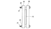
電池缶12内に捲回体10が装填され、かつ非水電解液が注入されたら、電池の初回充電を行う。充電は、捲回体10の膨張に起因する電池缶12の変形を規制した状態下に行う。具体的には図2及び図3に示すように、2枚の平板状のプレス部材20,20を用い、捲回体10が装填された電池缶12をこれら2枚のプレス部材20で挟み込み、電池缶12の変形を規制する。変形の規制は、電池缶12が最も変形しやすい部位に対して行うことが効果的である。この観点から、2枚のプレス部材20による挟み込みは、電池缶12における最大幅広面12aの側から行う。プレス部材20は例えばステンレスなどの高強度材料からなる。
When the
各プレス部材20は、所定厚みを有する矩形をしており、その四隅にボルト21の挿入用の孔22が設けられている。2枚のプレス部材20,20間に捲回体10が装填された電池缶12を挟み込み、更に一方のプレス部材20における孔22にボルト21を通し、そのボルト21を他方のプレス部材20における孔22に通す。そして、ボルト21をナット23で締めて、2枚のプレス部材20,20間に電池缶12を固定する。プレス部材20を用いた固定は、充電時に発生する膨張に起因する電池缶12の変形が規制されるように行うことが重要である。したがって、電池缶12の変形が規制される限り、2枚のプレス部材20,20を用いた固定によって、充電前の電池缶12に加圧力が加わってもよく、あるいは加わらなくてもよい。プレス部材20の材質及び捲回体10の膨張の程度にもよるが、加圧する場合には、加圧力は10kg/cm2以下、特に3kg/cm2以下であることが好ましい。
Each pressing
電池缶12を、図3に示すように固定した状態下に充電を行う。充電は、電池缶12を封口した状態で行ってもよく、封口しない状態で行ってもよい。封口しない状態で充電を行うと、初回充電の際に発生するガスを外部に除去できるので、通常使用時における充放電中の電池缶12の膨張変形を一層効果的に防止することができるという利点ある。尤も、この場合は、水分の存在しないドライルーム内で充電を行う必要がある。一方、封口状態で充電を行う場合には、ドライルームを用いる必要はない。しかし、この場合には初回充電の際に発生するガスが電池缶内に蓄積しないように注意する必要がある。 The battery can 12 is charged in a fixed state as shown in FIG. Charging may be performed with the battery can 12 sealed, or may be performed without sealing. If charging is performed without sealing, the gas generated during the first charge can be removed to the outside, so that the expansion deformation of the battery can 12 during charging and discharging during normal use can be more effectively prevented. is there. However, in this case, it is necessary to charge in a dry room where there is no moisture. On the other hand, when charging in a sealed state, there is no need to use a dry room. However, in this case, care must be taken so that the gas generated during the first charge does not accumulate in the battery can.
初回充電の条件の条件に特に制限はなく、従来と同様とすることができる。充電によって電極、特に負極が膨張し、それによって捲回体10が膨張する。捲回体10の膨張方向は、主として電極面と直交する方向である。この膨張に起因する捲回体10の体積の増加分は、上述した余剰スペースに吸収される。この場合、電池缶12の変形を規制しない状態下に充電を行うと、捲回体10は自由に(無秩序に)膨張し、極板が湾曲してしまうので、捲回体10の体積の増加分を首尾良く余剰スペースに吸収させることができない。これに対して、本実施形態によれば、電池缶12の変形を規制した状態下に捲回体10が膨張するので、極板が湾曲することなく捲回体10の体積の増加分は首尾良く余剰スペースに吸収される。このように、本実施形態においては、(イ)電池缶12内に余剰スペースを設けることと、(ロ)電池缶12の変形を規制した状態下に充電を行うこと(捲回体10を膨張させること)との組み合わせを採用することで、通常使用時における充放電中の電池缶の膨張変形を効果的に抑制することがはじめて可能となったものである。
There are no particular restrictions on the conditions for the initial charge, and it can be the same as the conventional one. Charging causes the electrodes, particularly the negative electrode, to expand, and thereby the
初回充電が完了したら、次いで初回放電を行う。初回放電の条件にも特に制限はなく、従来と同様とすることができる。初回放電は、プレス部材20を用いた規制を維持したまま行ってもよく、プレス部材20を用いた規制を解除した状態で行ってもよい。また、初回放電は、電池缶12を封口した状態で行ってもよく、封口しない状態で行ってもよい。
When the first charge is completed, the first discharge is then performed. There are no particular restrictions on the conditions for the first discharge, and the conditions can be the same as in the prior art. The initial discharge may be performed while the regulation using the
初回放電を、プレス部材20を用いた規制を解除した状態で行った場合には、その後、電池缶12の封口を行い(封口せずに初回放電を行った場合)、目的とする二次電池を得る。初回放電を、プレス部材20を用いた規制を維持したまま行った場合には、プレス部材20を用いた規制を解除して、目的とする二次電池を得る(但し、封口していないときには封口を行う)。あるいは、電池缶を封口した状態又は封口しない状態下に、プレス部材20を用いた規制を維持したまま、引き続き2回目の充電を行っても良い。一般に、プレス部材20を用いた規制を維持したまま充放電の回数を重ねると、通常使用時における充放電中の電池缶の膨張変形の程度が一層小さくなるので好ましい。この観点から、プレス部材20を用いた規制を維持したままの充放電の回数は2回以上、特に3回以上であることが好ましい。上限値に特に制限はないが、生産性の点から10回以下であることが好ましい。プレス部材20を用いた規制を維持したままの充放電を2回以上行う場合には、電池缶12は封口状態でもよく、封口しない状態でもよい。あるいは途中までは封口しない状態とし、途中から封口状態にしてもよい。
When the first discharge is performed in a state where the regulation using the
次に、本発明の第2ないし第6の実施形態について、図4ないし図9を参照しながら説明する。これらの実施形態に関し特に説明しない点については、先に述べた第1の実施形態に関する説明が適宜適用される。また、図4ないし図9において、図2及び図3と同じ部材には同じ符号を付してある。 Next, second to sixth embodiments of the present invention will be described with reference to FIGS. Regarding the points that are not particularly described with respect to these embodiments, the description regarding the first embodiment described above is appropriately applied. 4 to 9, the same members as those in FIGS. 2 and 3 are denoted by the same reference numerals.
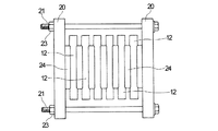
図4及び図5に示す第2の実施形態においては、2枚のプレス部材20による電池缶12の挟み込みに際して、局所的な加圧力を発生させるための補助プレス部材24を2枚用いる。補助プレス部材24は、所定の厚みを有する矩形状の平板からなる。補助プレス部材24は、電池缶12における最大幅広面12aの大きさよりも小さいものである。補助プレス部材24は、電池缶12とプレス部材20との間に配置されて、電池缶12における相対向する最大幅広面12aの中央域に対向当接される。この配置状態下に、ボルト21とナット23によって締め付けを行うと、電池缶12における相対向する最大幅広面12aの中央域のみが選択的に加圧され電池缶12の変形が規制される。先に説明した第1の実施形態では、2枚のプレス部材20によって、充電中の電池缶12の膨張変形を抑えるのに対し、補助プレス部材24を用いた本実施形態においては、補助プレス部材24によって発生する加圧力を、充電前の状態の電池缶12に対して積極的に与えている。最大幅広面12aの中央域は、電池缶12において最も膨張変形の程度が大きい部位であることから、当該部位を選択的に加圧することで、電池缶12の変形を効果的に規制することができ、通常使用時における充放電中の電池缶の膨張変形を一層効果的に抑制することができる。なお、本実施形態においては、プレス部材20と補助プレス部材24とを一体となしたものを用いてもよい。
In the second embodiment shown in FIGS. 4 and 5, two
本実施形態においては、加圧力を適宜調節することで、最大幅広面12aの中央域を補助プレス部材24によって押し込んで塑性変形させ、図5に示すように該中央域間の距離を、加圧前の距離よりも小さくしてもよい。このようにして得られた二次電池においては、通常使用時における充放電中の電池缶の膨張変形を更に一層効果的に抑制することができる。このことは、本製造方法によって得られる二次電池を、電池の容積の変動幅が厳しく制限されている機器、例えば携帯電話やパーソナルコンピュータに用いる場合に特に有効である。この観点から、相対向する中央域間の距離が、加圧前の距離の90〜99%、特に93〜98%となるように該中央域を選択的に加圧することが好ましい。このときの加圧力は0.5〜20kg/cm2、特に1〜5kg/cm2であることが好ましい。
In the present embodiment, by appropriately adjusting the pressing force, the central region of the maximum
これまで説明してきた実施形態は、1個の二次電池を製造する方法であったのに対し、図6及び図7に示す第3及び第4の実施形態は、複数個の二次電池を同時に製造する方法に係るものである。図6に示す実施形態においては、2枚のプレス部材20,20の間に複数個の電池缶12を並列配置し、これら複数個の電池缶12の最大幅広面を加圧して、該最大幅広面の変形を規制している。そして、この状態下に充放電を行う。
While the embodiment described so far is a method of manufacturing one secondary battery, the third and fourth embodiments shown in FIGS. 6 and 7 include a plurality of secondary batteries. It relates to a method of manufacturing at the same time. In the embodiment shown in FIG. 6, a plurality of
図7に示す実施形態においては、2枚のプレス部材20,20の間に複数個の電池缶12を並列配置し、かつ隣り合う電池缶12の間に補助プレス部材24を配置する。更に、プレス部材20と電池缶12との間にも補助プレス部材24を配置する。この配置状態下にボルト21とナット23によって締め付けを行い、各電池缶12における相対向する最大幅広面の中央域のみを選択的に加圧し、その変形を規制している。そして、この状態下に充放電を行う。
In the embodiment shown in FIG. 7, a plurality of
これまで説明してきた第1ないし第4の実施形態は、角型の二次電池の製造方法に係るものであったが、次に述べる第5の実施形態は円筒型の二次電池の製造方法に係るものである。 The first to fourth embodiments described so far relate to a method for manufacturing a rectangular secondary battery. The fifth embodiment described below is a method for manufacturing a cylindrical secondary battery. It is related to.
図8に示す第5の実施形態においては、上部が開口した有底の円筒状の電池缶12内に円柱状の捲回体10を装填する。本実施形態の電池缶12も、これまでの実施形態と同様に、捲回体10の体積分の容積に加えて、充電に起因する捲回体10の膨張体積に見合った分の余剰スペースを有する。本実施形態における捲回体10は円柱状なので、充電に起因する該捲回体10の膨張は、半径方向にほぼ均一に生じる。したがって、電池缶12内に設けられる余剰スペースの位置は、電池缶12の軸方向に対して直交する方向から視たとき、電池缶12の内壁と捲回体10の外面とで画成される円環域であることが好ましい。
In the fifth embodiment shown in FIG. 8, a
電池缶12内に捲回体10が装填され、かつ非水電解液が注入されたら、電池の初回充電を行う。充電は、捲回体10の膨張に起因する電池缶12の変形を規制した状態下に行う。具体的には図8及び図9に示すように、プレス部材20として、直方体状のブロック体の一側面を、半円柱状にくり抜いたものを2個用いる。プレス部材20の平面視におけるくり抜き部位25の曲率は、電池缶12の平面視における曲率と同じになっている。このような形状を有する2個のプレス部材20,20を用い、捲回体10が装填された電池缶12をこれら2個のプレス部材20のくり抜き部位25に挟み込み、ボルト21とナット23で締め付けて電池缶12の変形を規制する。この状態下に充電を行う。充電の条件及びその他の手順は、先に述べた実施形態と同様である。
When the
図9に示す第6の実施形態は、図8に示す実施形態の変形例である。図8に示す実施形態は1個の二次電池を製造する方法であったのに対し、図9に示す実施形態は、複数個の二次電池を同時に製造する方法に係るものである。本実施形態においては、図8に示す実施形態で用いたプレス部材20と同様のものを2個用いる。これに加えて、直方体状のブロック体における相対向する2つの側面の同じ位置を、半円柱状にくり抜いたものを、第2のプレス部材20’として1個以上用いる(図9では4個用いている。)。このくり抜き部位の形状は、プレス部材20におけるくり抜き部位の形状と同じである。
The sixth embodiment shown in FIG. 9 is a modification of the embodiment shown in FIG. The embodiment shown in FIG. 8 is a method for manufacturing a single secondary battery, whereas the embodiment shown in FIG. 9 relates to a method for manufacturing a plurality of secondary batteries simultaneously. In the present embodiment, two
プレス部材20及び第2のプレス部材20’は、これらが一直線上に並ぶように直列配置される。この場合、2個のプレス部材20がそれぞれ両端に位置するように配置され、第2のプレス部材20’が2個のプレス部材20間に位置するように配置される。そして、プレス部材20と第2のプレス部材20’との間で、半円柱状のくり抜き部位25が対向し、かつ隣り合う2つの第2のプレス部材20’間においても半円柱状のくり抜き部位が対向するようになっている。このような配置状態下に、対向する2つのくり抜き部位の間に、捲回体が装填された電池缶12を挟み込み、ボルト21とナット23で締め付けて電池缶12の変形を規制する。この状態下に充電を行う。
The
次に、前記の各実施形態において用いられる部材の詳細について説明する。正極は、正極活物質並びに必要により導電剤及び結着剤を適当な溶媒に懸濁し、正極合剤を作製し、これをアルミニウム等からなる集電体に塗布、乾燥した後、ロール圧延、プレスし、更に裁断、打ち抜きすることにより得られる。つまり正極は、集電体の一面又は両面に正極活物質層が形成されたものである。正極活物質としては、リチウムニッケル複合酸化物、リチウムマンガン複合酸化物、リチウムコバルト複合酸化物等の含リチウム遷移金属複合酸化物を始めとする従来公知の正極活物質が用いられる。また、正極活物質として、LiCoO2に少なくともZrとMgの両方を含有させたリチウム遷移金属複合酸化物と、層状構造を有し、少なくともMnとNiの両方を含有するリチウム遷移金属複合酸化物と混合したものも好ましく用いることができる。かかる正極活物質を用いることで充放電サイクル特性及び熱安定性の低下を伴うことなく、充電終止電圧を高めることが期待できる。正極活物質の一次粒子径の平均値は5μm以上10μm以下であることが、充填密度と反応面積との兼ね合いから好ましく、正極に使用する結着剤の重量平均分子量は350,000 以上2,000,000以下のポリフッ化ビニリデンであることが好ましい。低温環境での放電特性を向上させることが期待できるからである。 Next, details of members used in each of the above-described embodiments will be described. The positive electrode is prepared by suspending a positive electrode active material and, if necessary, a conductive agent and a binder in an appropriate solvent to produce a positive electrode mixture, applying this to a current collector made of aluminum or the like, drying, roll rolling, pressing It is obtained by further cutting and punching. That is, the positive electrode is one in which a positive electrode active material layer is formed on one surface or both surfaces of a current collector. As the positive electrode active material, conventionally known positive electrode active materials such as lithium-containing transition metal composite oxides such as lithium nickel composite oxide, lithium manganese composite oxide, and lithium cobalt composite oxide are used. Further, as the positive electrode active material, a lithium transition metal composite oxide in which LiCoO 2 contains at least both Zr and Mg, a lithium transition metal composite oxide having a layered structure and containing at least both Mn and Ni, A mixture thereof can also be preferably used. The use of such a positive electrode active material can be expected to increase the end-of-charge voltage without deteriorating charge / discharge cycle characteristics and thermal stability. The average value of the primary particle diameter of the positive electrode active material is preferably 5 μm or more and 10 μm or less in view of the packing density and the reaction area, and the weight average molecular weight of the binder used for the positive electrode is 350,000 or more and 2,000. It is preferable that the polyvinylidene fluoride is 1,000 or less. This is because it can be expected to improve discharge characteristics in a low temperature environment.
負極としては、集電体の一面又は両面に負極活物質を含む活物質層が形成されてなるものが用いられる。負極活物質としては、例えば天然黒鉛、人造黒鉛、ハードカーボン、ソフトカーボンなどのグラファイト系の材料、シリコンを含む材料、スズを含む材料、アルミニウムを含む材料、ゲルマニウムを含む材料が挙げられる。スズを含む材料としては、例えばスズと、コバルトと、炭素と、ニッケル及びクロムのうちの少なくとも一方とを含む合金が好ましく用いられる。負極重量あたりの容量密度を向上させる上では、特にシリコンを含む材料が好ましい。また、シリコンを含む材料及びスズを含む材料は、充電時の膨張の程度が極めて大きいので、本発明の製造方法を行った場合に、その効果が最も顕著に発現する材料である。 As the negative electrode, one in which an active material layer containing a negative electrode active material is formed on one surface or both surfaces of a current collector is used. Examples of the negative electrode active material include graphite-based materials such as natural graphite, artificial graphite, hard carbon, and soft carbon, silicon-containing materials, tin-containing materials, aluminum-containing materials, and germanium-containing materials. As the material containing tin, for example, an alloy containing tin, cobalt, carbon, and at least one of nickel and chromium is preferably used. In order to improve the capacity density per weight of the negative electrode, a material containing silicon is particularly preferable. In addition, since the material containing silicon and the material containing tin have a very large degree of expansion at the time of charging, the effect is most prominent when the manufacturing method of the present invention is performed.
シリコンを含む材料としては、リチウムの吸蔵が可能でかつシリコンを含有する材料、例えばシリコン単体、シリコンと金属との合金、シリコン酸化物などを用いることができる。これらの材料はそれぞれ単独で、あるいはこれらを混合して用いることができる。前記の金属としては、例えばCu、Ni、Co、Cr、Fe、Ti、Pt、W、Mo及びAuからなる群から選択される1種類以上の元素が挙げられる。これらの金属のうち、Cu、Ni、Coが好ましい。特に電子伝導性に優れる点、及びリチウム化合物の形成能の低さの点から、Cu、Niを用いることが望ましい。また、負極を電池に組み込む前に、又は組み込んだ後に、シリコンを含む材料からなる活物質に対してリチウムを吸蔵させてもよい。特に好ましいシリコンを含む材料は、リチウムの吸蔵量の高さの点からシリコン単体又はシリコン酸化物である。 As a material containing silicon, a material that can occlude lithium and contains silicon, for example, silicon alone, an alloy of silicon and metal, silicon oxide, or the like can be used. These materials can be used alone or in combination. Examples of the metal include one or more elements selected from the group consisting of Cu, Ni, Co, Cr, Fe, Ti, Pt, W, Mo, and Au. Of these metals, Cu, Ni, and Co are preferable. In particular, Cu and Ni are desirably used from the viewpoint of excellent electronic conductivity and low ability to form a lithium compound. Further, lithium may be occluded in an active material made of a material containing silicon before or after the negative electrode is incorporated in the battery. A particularly preferable silicon-containing material is silicon alone or silicon oxide in view of the high occlusion amount of lithium.
負極活物質層は、物理気相蒸着法や化学気相蒸着法等の乾式薄膜製造方法、電解めっき法や無電解めっき法などの湿式薄膜製造方法によって形成することができる。また、活物質を含む粒子を含有するスラリーを集電体上に塗布して塗膜を形成し、該塗膜を焼結して活物質層を形成することもできる。また、本出願人の先の出願に係るWO2007/46327に記載の構造を有する負極活物質層を採用することもできる。この公報に記載の負極活物質層は、活物質を含む粒子を有し、該粒子の表面の少なくとも一部がリチウム化合物の形成能の低い金属材料で被覆されていると共に、該金属材料で被覆された該粒子どうしの間に空隙が形成されているものである。該金属材料は、活物質層の厚み方向の全域にわたって存在しており、導電性のネットワークを形成している。 The negative electrode active material layer can be formed by a dry thin film manufacturing method such as physical vapor deposition or chemical vapor deposition, or a wet thin film manufacturing method such as electrolytic plating or electroless plating. Alternatively, a slurry containing particles containing an active material can be applied onto a current collector to form a coating film, and the coating film can be sintered to form an active material layer. Moreover, the negative electrode active material layer which has a structure as described in WO2007 / 46327 concerning the previous application of the present applicant can also be adopted. The negative electrode active material layer described in this publication has particles containing an active material, and at least a part of the surface of the particles is coated with a metal material having a low ability to form a lithium compound and is coated with the metal material. A void is formed between the formed particles. The metal material is present throughout the active material layer in the thickness direction, and forms a conductive network.
セパレータとしては、合成樹脂製不織布、ポリエチレンやポリプロピレン等のポリオレフィン、又はポリテトラフルオロエチレンの多孔質フィルム等が好ましく用いられる。特にセパレータとして、例えば多孔性ポリオレフィンフィルム(旭化成ケミカルズ製;N9420G)が好ましく使用できる。電池の過充電時に生じる電極の発熱を抑制する観点からは、ポリオレフィン微多孔膜の片面又は両面にフェロセン誘導体の薄膜が形成されてなるセパレータを用いることが好ましい。セパレータは、突刺強度が0.2N/μm厚以上0.49N/μm厚以下であり、捲回軸方向の引張強度が40MPa以上150MPa以下であることが好ましい。充放電に伴い大きく膨張・収縮する負極活物質を用いても、セパレータの損傷を抑制することができ、内部短絡の発生を抑制することができるからである。 As the separator, a synthetic resin nonwoven fabric, a polyolefin such as polyethylene or polypropylene, or a polytetrafluoroethylene porous film is preferably used. In particular, for example, a porous polyolefin film (manufactured by Asahi Kasei Chemicals; N9420G) can be preferably used as the separator. From the viewpoint of suppressing the heat generation of the electrode that occurs when the battery is overcharged, it is preferable to use a separator in which a thin film of a ferrocene derivative is formed on one side or both sides of a polyolefin microporous membrane. The separator preferably has a puncture strength of 0.2 N / μm thickness or more and 0.49 N / μm thickness or less, and a tensile strength in the winding axis direction of 40 MPa or more and 150 MPa or less. This is because even when a negative electrode active material that greatly expands and contracts with charge and discharge is used, damage to the separator can be suppressed, and occurrence of internal short circuits can be suppressed.
非水電解液は、支持電解質であるリチウム塩を有機溶媒に溶解した溶液からなる。リチウム塩としては、LiClO4、LiA1Cl4、LiPF6、LiAsF6、LiSbF6、LiBF4、LiSCN、LiCl、LiBr、LiI、LiCF3SO3、LiC4F9SO3等が例示される。有機溶媒としては、例えばエチレンカーボネート、ジエチルカーボネート、ジメチルカーボネート、プロピレンカーボネート、ブチレンカーボネート等が挙げられる。特に、非水電解液全体に対し0.5 〜5重量%のビニレンカーボネート及び0.1〜1重量%のジビニルスルホン、0.1〜1.5重量%の1,4−ブタンジオールジメタンスルホネートを含有させることが充放電サイクル特性を更に向上する観点から好ましい。 The nonaqueous electrolytic solution is a solution in which a lithium salt as a supporting electrolyte is dissolved in an organic solvent. Examples of the lithium salt include LiClO 4 , LiA1Cl 4 , LiPF 6 , LiAsF 6 , LiSbF 6 , LiBF 4 , LiSCN, LiCl, LiBr, LiI, LiCF 3 SO 3 , LiC 4 F 9 SO 3 and the like. Examples of the organic solvent include ethylene carbonate, diethyl carbonate, dimethyl carbonate, propylene carbonate, butylene carbonate, and the like. In particular, 0.5 to 5% by weight of vinylene carbonate and 0.1 to 1% by weight of divinyl sulfone and 0.1 to 1.5% by weight of 1,4-butanediol dimethanesulfonate with respect to the whole non-aqueous electrolyte. It is preferable from the viewpoint of further improving the charge / discharge cycle characteristics.
以上、本発明をその好ましい実施形態に基づき説明したが、本発明は前記実施形態に制限されない。例えば前記実施形態においては、図2及び図4に示す実施形態は、単一の角型電池を対象とするものであったが、これに代えて、角型の複数の単セルをスタックした状態の電池を対象としてもよい。 As mentioned above, although this invention was demonstrated based on the preferable embodiment, this invention is not restrict | limited to the said embodiment. For example, in the above embodiment, the embodiment shown in FIGS. 2 and 4 is intended for a single prismatic battery, but instead, a state in which a plurality of prismatic single cells are stacked. The battery may be the target.
以下、実施例により本発明を更に詳細に説明する。しかしながら本発明の範囲は、かかる実施例に制限されない。特に断らない限り、「%」及び「部」はそれぞれ「重量%」及び「重量部」を意味する。 Hereinafter, the present invention will be described in more detail with reference to examples. However, the scope of the present invention is not limited to such examples. Unless otherwise specified, “%” and “part” mean “% by weight” and “part by weight”, respectively.
〔実施例1〕
(1)正極の製造
正極活物質としてLiCo1/3Ni1/3Mn1/3O2を用いた。これを、アセチレンブラック及びポリフッ化ビニリデンとともに、溶媒であるN−メチルピロリドンに懸濁させ正極合剤を得た。配合の重量比は、正極活物質:アセチレンブラック:ポリフッ化ビニリデン=88:6:6とした。この正極合剤をアルミニウム箔(厚さ20μm)からなる集電体の各面にアプリケータを用いて塗布し、120℃で乾燥した後、荷重0.5ton/cmのロールプレスを行い、正極を得た。
[Example 1]
(1) Production of positive electrode LiCo 1/3 Ni 1/3 Mn 1/3 O 2 was used as a positive electrode active material. This was suspended in N-methylpyrrolidone as a solvent together with acetylene black and polyvinylidene fluoride to obtain a positive electrode mixture. The weight ratio of the blending was positive electrode active material: acetylene black: polyvinylidene fluoride = 88: 6: 6. This positive electrode mixture was applied to each surface of a current collector made of aluminum foil (
(2)負極の製造
本出願人の先の出願に係るWO2007/46327に記載の方法に準じて負極を製造した。厚さ18μmの電解銅箔からなる集電体を室温で30秒間酸洗浄した。次いで15秒間純水洗浄した。活物質の粒子として平均粒径D50が2.5μmであるSi単体の粒子を用いた。活物質の粒子100部に対して、結着剤としてのスチレンブタジエンラバーを1.7部用いた。また導電材としてのアセチレンブラックを2部で用いた。これらをN−メチルピロリドンに分散させてスラリーとなした。このスラリーを、膜厚15μmになるように集電体の各面に塗布し塗膜を形成した。塗膜が形成された集電体を、以下の浴組成を有するピロリン酸銅浴に浸漬させ、電解により、塗膜に対して銅のめっきを行い、活物質層を形成した。電解の条件は以下のとおりとした。陽極にはDSEを用いた。電源は直流電源を用いた。このようにして得られた負極活物質層においては、活物質の粒子の表面の少なくとも一部が銅で被覆されていると共に、銅で被覆された該粒子どうしの間に空隙が形成されていた。銅の被覆は、活物質層の厚み方向の全域にわたって存在していた。
・ピロリン酸銅三水和物:105g/l
・ピロリン酸カリウム:450g/l
・硝酸カリウム:30g/l
・浴温度:50℃
・電流密度:3A/dm2
・pH:アンモニア水とポリリン酸を添加してpH8.2になるように調整した。
(2) Manufacture of negative electrode A negative electrode was manufactured according to the method described in WO2007 / 46327 related to the previous application of the present applicant. A current collector made of an electrolytic copper foil having a thickness of 18 μm was acid washed at room temperature for 30 seconds. Subsequently, it was washed with pure water for 15 seconds. Si particles having an average particle diameter D 50 of 2.5 μm were used as the active material particles. 1.7 parts of styrene butadiene rubber as a binder was used with respect to 100 parts of the active material particles. Further, acetylene black as a conductive material was used in 2 parts. These were dispersed in N-methylpyrrolidone to form a slurry. This slurry was applied to each surface of the current collector so as to have a film thickness of 15 μm to form a coating film. The current collector on which the coating film was formed was immersed in a copper pyrophosphate bath having the following bath composition, and copper was plated on the coating film by electrolysis to form an active material layer. The electrolysis conditions were as follows. DSE was used for the anode. A DC power source was used as the power source. In the negative electrode active material layer thus obtained, at least part of the surface of the active material particles was covered with copper, and voids were formed between the copper-coated particles. . The copper coating was present throughout the active material layer in the thickness direction.
Copper pyrophosphate trihydrate: 105 g / l
-Potassium pyrophosphate: 450 g / l
・ Potassium nitrate: 30 g / l
・ Bath temperature: 50 ° C
・ Current density: 3 A / dm 2
-PH: Ammonia water and polyphosphoric acid were added to adjust to pH 8.2.
(3)リチウム二次電池の製造
得られた正極及び負極を、ポリプロピレン製多孔質フィルムからなるセパレータとともに用いて円筒形の捲回体を得た。この捲回体をその軸方向と直交する方向から加圧して扁平体となした。この扁平な捲回体の充放電による膨張体積は、膨張前の体積に対して150%であった。この膨張体積に見合った分の余剰スペースを有する角型電池缶に捲回体を装填し、更に非水電解液を注入した。そして電池缶を図2に示す装置に取り付け、図3に示すように電池缶の変形を規制した。このとき、電池缶に圧力を加えなかった。この状態下に初回充放電を行った。充放電は、電池缶を封口しないで行った。充電条件は、終止電圧4.2V、レート0.05Cで定電流・定電圧とした。放電条件は、終止電圧2.7V、レート0.05Cで定電流とした。放電完了後、変形の規制状態を解除し、電池缶を常法によって封口して目的とするリチウム二次電池を得た。これら一連の操作はドライルーム中で行った。充電中に電池缶の膨張で発生した圧力は最大で10kg/cm2であった。
(3) Manufacture of lithium secondary battery The obtained positive electrode and negative electrode were used together with a separator made of a polypropylene porous film to obtain a cylindrical wound body. The wound body was pressed from a direction orthogonal to the axial direction to form a flat body. The expansion volume due to charging / discharging of this flat wound body was 150% with respect to the volume before expansion. The wound body was loaded into a prismatic battery can having an excess space corresponding to the expanded volume, and a non-aqueous electrolyte was further injected. And the battery can was attached to the apparatus shown in FIG. 2, and the deformation | transformation of the battery can was controlled as shown in FIG. At this time, no pressure was applied to the battery can. Under this condition, first charge / discharge was performed. Charging / discharging was performed without sealing the battery can. The charging conditions were a final voltage of 4.2 V, a rate of 0.05 C, and a constant current / constant voltage. The discharge conditions were a constant current at a final voltage of 2.7 V and a rate of 0.05 C. After completion of the discharge, the deformation restriction state was released, and the battery can was sealed by a conventional method to obtain the intended lithium secondary battery. These series of operations were performed in a dry room. The pressure generated by the expansion of the battery can during charging was 10 kg / cm 2 at maximum.
〔実施例2〕
プレス部材を用いた変形の規制状態を維持したまま充放電を2回繰り返した。その後は実施例1と同様にしてリチウム二次電池を得た。初回の充放電条件は、実施例1と同様とした。2回目の充電放条件は、初回の充放電条件と同様とした。
[Example 2]
Charging / discharging was repeated twice while maintaining the deformation restricted state using the press member. Thereafter, a lithium secondary battery was obtained in the same manner as in Example 1. The initial charge / discharge conditions were the same as in Example 1. The second charging / discharging conditions were the same as the first charging / discharging conditions.
〔実施例3〕
プレス部材を用いた変形の規制状態を維持したまま充放電を5回繰り返した。その後は実施例1と同様にしてリチウム二次電池を得た。初回の充放電条件は、実施例1と同様とした。6回目以降の充電条件は、終止電圧4.2V、レート0.5Cで定電流・定電圧とした。放電条件は、終止電圧2.7V、レート0.5Cで定電流とした。
Example 3
Charging / discharging was repeated 5 times while maintaining the restricted state of deformation using the press member. Thereafter, a lithium secondary battery was obtained in the same manner as in Example 1. The initial charge / discharge conditions were the same as in Example 1. The charging conditions after the sixth time were a constant current and a constant voltage at a final voltage of 4.2 V and a rate of 0.5 C. The discharge conditions were a final voltage of 2.7 V and a constant current of 0.5 C.
〔比較例1〕
電池缶の内容積と捲回体の体積とがほぼ同じになるように捲回体の体積を調整した。この捲回体を電池缶内に装填した。装填状態において、電池缶の内壁と捲回体の外面との間には隙間はほとんど存在していなかった。この電池缶を封口しない状態で、実施例1と同様にして充放電を1回行った。充放電中における電池缶の変形は規制しなかった。その後は実施例1と同様にしてリチウム二次電池を得た。
[Comparative Example 1]
The volume of the wound body was adjusted so that the inner volume of the battery can and the volume of the wound body were substantially the same. This wound body was loaded into a battery can. In the loaded state, there was almost no gap between the inner wall of the battery can and the outer surface of the wound body. The battery can was charged and discharged once in the same manner as in Example 1 without sealing the battery can. The deformation of the battery can during charging / discharging was not regulated. Thereafter, a lithium secondary battery was obtained in the same manner as in Example 1.
〔比較例2〕
本比較例は、特許文献1に記載の方法と類似の方法である。比較例1において、充電終了後、電池缶に10kg/cm2の圧力を加えて電池缶を変形させた。加圧された状態での最大幅広面間の距離は、加圧前の距離の95%であった。その後は実施例1と同様にしてリチウム二次電池を得た。
[Comparative Example 2]
This comparative example is a method similar to the method described in Patent Document 1. In Comparative Example 1, after charging was completed, the battery can was deformed by applying a pressure of 10 kg / cm 2 to the battery can. The distance between the maximum wide surfaces in the pressed state was 95% of the distance before pressing. Thereafter, a lithium secondary battery was obtained in the same manner as in Example 1.
〔評価〕
実施例及び比較例で得られた電池について、充放電を繰り返した。充電条件は、終止電圧4.2V、レート0.5Cで定電流・定電圧とした。放電条件は、終止電圧2.7V、レート0.5Cで定電流とした。そして、1回目の充電が完了した時点での電池の膨張率、及び100回目の充電が完了した時点での電池の膨張率を測定した。その結果を表1に示す。サンプル数は、各実施例及び各比較例ともにn=5とした。電池の膨張率は次の方法で測定した。
[Evaluation]
Charging / discharging was repeated about the battery obtained by the Example and the comparative example. The charging conditions were a final voltage of 4.2 V, a rate of 0.5 C, and a constant current / constant voltage. The discharge conditions were a final voltage of 2.7 V and a constant current of 0.5 C. And the expansion coefficient of the battery when the 1st charge was completed and the expansion coefficient of the battery when the 100th charge was completed were measured. The results are shown in Table 1. The number of samples was set to n = 5 in each example and each comparative example. The expansion coefficient of the battery was measured by the following method.
〔電池の膨張率の測定方法〕
マイクロメータを用い、電池の最大幅広面の中央部の位置における厚みの増加を測定し、その値から膨張率を算出した。
[Measurement method of battery expansion coefficient]
Using a micrometer, the increase in thickness at the central portion of the maximum wide surface of the battery was measured, and the expansion coefficient was calculated from the value.
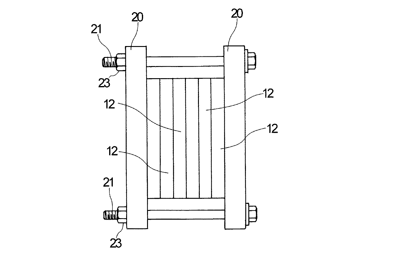
表1に示す結果から明らかなように、実施例で得られた電池は、比較例で得られた電池に比べて充電時の膨張率が小さいことが判る。特に、比較例で得られた電池では、充放電のサイクルを繰り返すと、膨張率の増加率が非常に大きくなるのに対し、実施例で得られた電池では、充放電のサイクルを繰り返しても、膨張率の増加率が小さい範囲にとどまることが判る。 As is clear from the results shown in Table 1, it can be seen that the battery obtained in the example has a smaller expansion coefficient at the time of charging than the battery obtained in the comparative example. In particular, in the battery obtained in the comparative example, when the charge / discharge cycle is repeated, the rate of increase in the expansion rate becomes very large, whereas in the battery obtained in the example, the charge / discharge cycle is repeated. It can be seen that the rate of increase of the expansion rate remains in a small range.
10 捲回体
12 電池缶
20 プレス部材
24 補助プレス部材
10
Claims (7)
充電に起因する捲回体の膨張体積に見合った分の余剰スペースを有する電池缶内に該捲回体を装填し、
次いで該捲回体の膨張に起因する電池缶の変形を規制した状態下に充電を行うことを特徴とする非水電解液二次電池の製造方法。 A positive electrode and a negative electrode containing an active material capable of reversibly occluding and releasing lithium ions, and a wound body in which a separator interposed between them is wound together are loaded into a battery can, and then charged. In the method for producing a non-aqueous electrolyte secondary battery having a step of performing,
The winding body is loaded into a battery can having a surplus space corresponding to the expansion volume of the winding body due to charging,
Next, charging is performed in a state where deformation of the battery can due to expansion of the wound body is restricted, and a method for manufacturing a nonaqueous electrolyte secondary battery.
Priority Applications (1)
| Application Number | Priority Date | Filing Date | Title |
|---|---|---|---|
| JP2007275763A JP2009104902A (en) | 2007-10-23 | 2007-10-23 | Method for producing non-aqueous electrolyte secondary battery |
Applications Claiming Priority (1)
| Application Number | Priority Date | Filing Date | Title |
|---|---|---|---|
| JP2007275763A JP2009104902A (en) | 2007-10-23 | 2007-10-23 | Method for producing non-aqueous electrolyte secondary battery |
Publications (1)
| Publication Number | Publication Date |
|---|---|
| JP2009104902A true JP2009104902A (en) | 2009-05-14 |
Family
ID=40706372
Family Applications (1)
| Application Number | Title | Priority Date | Filing Date |
|---|---|---|---|
| JP2007275763A Withdrawn JP2009104902A (en) | 2007-10-23 | 2007-10-23 | Method for producing non-aqueous electrolyte secondary battery |
Country Status (1)
| Country | Link |
|---|---|
| JP (1) | JP2009104902A (en) |
Cited By (22)
| Publication number | Priority date | Publication date | Assignee | Title |
|---|---|---|---|---|
| JP2011530784A (en) * | 2008-08-05 | 2011-12-22 | シオン・パワー・コーポレーション | Force application in electrochemical cells |
| CN102593520A (en) * | 2012-02-20 | 2012-07-18 | 宁德新能源科技有限公司 | Method for improving hardness of lithium ion cell |
| JP2014035928A (en) * | 2012-08-09 | 2014-02-24 | Sanyo Electric Co Ltd | Non-aqueous electrolyte secondary battery |
| JP2014116237A (en) * | 2012-12-11 | 2014-06-26 | Sei Kk | Electrochemical device |
| US9040197B2 (en) | 2011-10-13 | 2015-05-26 | Sion Power Corporation | Electrode structure and method for making the same |
| KR20160050839A (en) * | 2014-10-31 | 2016-05-11 | 주식회사 엘지화학 | Battery module and coupling means having reinforcing structure for swelling of battery cell |
| CN105762405A (en) * | 2016-05-20 | 2016-07-13 | 宁德时代新能源科技股份有限公司 | Battery cell and forming method thereof |
| US9548492B2 (en) | 2011-06-17 | 2017-01-17 | Sion Power Corporation | Plating technique for electrode |
| US9577267B2 (en) | 2012-12-19 | 2017-02-21 | Sion Power Corporation | Electrode structure and method for making same |
| KR101798708B1 (en) * | 2015-04-09 | 2017-11-16 | 주식회사 엘지화학 | Charging and Discharging Device of Battery Cell |
| CN109148935A (en) * | 2013-03-14 | 2019-01-04 | 新强能电池公司 | Chucking device for electrochemical cell stack |
| US10319988B2 (en) | 2014-05-01 | 2019-06-11 | Sion Power Corporation | Electrode fabrication methods and associated systems and articles |
| US10629947B2 (en) | 2008-08-05 | 2020-04-21 | Sion Power Corporation | Electrochemical cell |
| JPWO2021065128A1 (en) * | 2019-09-30 | 2021-04-08 | ||
| US11791511B2 (en) | 2019-11-19 | 2023-10-17 | Sion Power Corporation | Thermally insulating compressible components for battery packs |
| US11824228B2 (en) | 2019-11-19 | 2023-11-21 | Sion Power Corporation | Compression systems for batteries |
| US11923495B2 (en) | 2020-03-13 | 2024-03-05 | Sion Power Corporation | Application of pressure to electrochemical devices including deformable solids, and related systems |
| US11978917B2 (en) | 2019-11-19 | 2024-05-07 | Sion Power Corporation | Batteries with components including carbon fiber, and associated systems and methods |
| US11984575B2 (en) | 2019-11-19 | 2024-05-14 | Sion Power Corporation | Battery alignment, and associated systems and methods |
| JP2024070095A (en) * | 2022-11-10 | 2024-05-22 | プライムプラネットエナジー&ソリューションズ株式会社 | Secondary battery control method |
| DE102022126117B4 (en) | 2022-01-24 | 2025-02-13 | GM Global Technology Operations LLC | Battery-powered electrical device for use with an electrical consumer |
| US12394817B2 (en) | 2019-06-21 | 2025-08-19 | Sion Power Corporation | Methods, systems, and devices for applying forces to electrochemical devices |
-
2007
- 2007-10-23 JP JP2007275763A patent/JP2009104902A/en not_active Withdrawn
Cited By (40)
| Publication number | Priority date | Publication date | Assignee | Title |
|---|---|---|---|---|
| US11108076B2 (en) | 2008-08-05 | 2021-08-31 | Sion Power Corporation | Application of force in electrochemical cells |
| JP2011530784A (en) * | 2008-08-05 | 2011-12-22 | シオン・パワー・コーポレーション | Force application in electrochemical cells |
| US10629947B2 (en) | 2008-08-05 | 2020-04-21 | Sion Power Corporation | Electrochemical cell |
| US10312545B2 (en) | 2008-08-05 | 2019-06-04 | Sion Power Corporation | Application of force in electrochemical cells |
| US11108077B2 (en) | 2008-08-05 | 2021-08-31 | Sion Power Corporation | Application of force in electrochemical cells |
| US9105938B2 (en) | 2008-08-05 | 2015-08-11 | Sion Power Corporation | Application of force in electrochemical cells |
| US10320027B2 (en) | 2008-08-05 | 2019-06-11 | Sion Power Corporation | Application of force in electrochemical cells |
| US11735761B2 (en) | 2008-08-05 | 2023-08-22 | Sion Power Corporation | Application of force in electrochemical cells |
| US11121397B2 (en) | 2008-08-05 | 2021-09-14 | Sion Power Corporation | Application of force in electrochemical cells |
| US9780404B2 (en) | 2008-08-05 | 2017-10-03 | Sion Power Corporation | Application of force in electrochemical cells |
| US9548492B2 (en) | 2011-06-17 | 2017-01-17 | Sion Power Corporation | Plating technique for electrode |
| US11456459B2 (en) | 2011-06-17 | 2022-09-27 | Sion Power Corporation | Plating technique for electrode |
| US9040197B2 (en) | 2011-10-13 | 2015-05-26 | Sion Power Corporation | Electrode structure and method for making the same |
| CN102593520A (en) * | 2012-02-20 | 2012-07-18 | 宁德新能源科技有限公司 | Method for improving hardness of lithium ion cell |
| JP2014035928A (en) * | 2012-08-09 | 2014-02-24 | Sanyo Electric Co Ltd | Non-aqueous electrolyte secondary battery |
| JP2014116237A (en) * | 2012-12-11 | 2014-06-26 | Sei Kk | Electrochemical device |
| US9577267B2 (en) | 2012-12-19 | 2017-02-21 | Sion Power Corporation | Electrode structure and method for making same |
| JP2019140115A (en) * | 2013-03-14 | 2019-08-22 | エネヴェート・コーポレーション | Clamping device for electrochemical cell stack |
| CN109148935A (en) * | 2013-03-14 | 2019-01-04 | 新强能电池公司 | Chucking device for electrochemical cell stack |
| JP2021099998A (en) * | 2013-03-14 | 2021-07-01 | エネヴェート・コーポレーション | Clamping device for electrochemical cell stack |
| US10319988B2 (en) | 2014-05-01 | 2019-06-11 | Sion Power Corporation | Electrode fabrication methods and associated systems and articles |
| KR20160050839A (en) * | 2014-10-31 | 2016-05-11 | 주식회사 엘지화학 | Battery module and coupling means having reinforcing structure for swelling of battery cell |
| KR101696913B1 (en) | 2014-10-31 | 2017-01-16 | 주식회사 엘지화학 | Battery module and coupling means having reinforcing structure for swelling of battery cell |
| KR101798708B1 (en) * | 2015-04-09 | 2017-11-16 | 주식회사 엘지화학 | Charging and Discharging Device of Battery Cell |
| CN105762405A (en) * | 2016-05-20 | 2016-07-13 | 宁德时代新能源科技股份有限公司 | Battery cell and forming method thereof |
| US12394817B2 (en) | 2019-06-21 | 2025-08-19 | Sion Power Corporation | Methods, systems, and devices for applying forces to electrochemical devices |
| WO2021065128A1 (en) * | 2019-09-30 | 2021-04-08 | 三洋電機株式会社 | Method for producing nonaqueous electrolyte secondary battery, and nonaqueous electrolyte secondary battery |
| US12388121B2 (en) | 2019-09-30 | 2025-08-12 | Sanyo Electric Co., Ltd. | Method for producing nonaqueous electrolyte secondary battery, and nonaqueous electrolyte secondary battery |
| JPWO2021065128A1 (en) * | 2019-09-30 | 2021-04-08 | ||
| JP7621265B2 (en) | 2019-09-30 | 2025-01-24 | 三洋電機株式会社 | Method for manufacturing non-aqueous electrolyte secondary battery and non-aqueous electrolyte secondary battery |
| US11824228B2 (en) | 2019-11-19 | 2023-11-21 | Sion Power Corporation | Compression systems for batteries |
| US11929523B2 (en) | 2019-11-19 | 2024-03-12 | Sion Power Corporation | Batteries, and associated systems and methods |
| US11978917B2 (en) | 2019-11-19 | 2024-05-07 | Sion Power Corporation | Batteries with components including carbon fiber, and associated systems and methods |
| US11984575B2 (en) | 2019-11-19 | 2024-05-14 | Sion Power Corporation | Battery alignment, and associated systems and methods |
| US12051829B2 (en) | 2019-11-19 | 2024-07-30 | Sion Power Corporation | Systems and methods for applying and maintaining compression pressure on electrochemical cells |
| US11791511B2 (en) | 2019-11-19 | 2023-10-17 | Sion Power Corporation | Thermally insulating compressible components for battery packs |
| US11923495B2 (en) | 2020-03-13 | 2024-03-05 | Sion Power Corporation | Application of pressure to electrochemical devices including deformable solids, and related systems |
| DE102022126117B4 (en) | 2022-01-24 | 2025-02-13 | GM Global Technology Operations LLC | Battery-powered electrical device for use with an electrical consumer |
| JP7710426B2 (en) | 2022-11-10 | 2025-07-18 | プライムプラネットエナジー&ソリューションズ株式会社 | Secondary battery control method |
| JP2024070095A (en) * | 2022-11-10 | 2024-05-22 | プライムプラネットエナジー&ソリューションズ株式会社 | Secondary battery control method |
Similar Documents
| Publication | Publication Date | Title |
|---|---|---|
| JP2009104902A (en) | Method for producing non-aqueous electrolyte secondary battery | |
| JP5182477B2 (en) | Non-aqueous secondary battery | |
| US9312559B2 (en) | Nonaqueous electrolyte secondary battery provided with a wound electrode body | |
| JP6448336B2 (en) | Method for producing lithium ion secondary battery | |
| JP7170330B2 (en) | Negative electrode for secondary battery and secondary battery | |
| KR102146360B1 (en) | Hybrid carbon nanotube and graphene nanostructures | |
| CN101405898B (en) | Non-aqueous electrolyte secondary battery | |
| JP5260887B2 (en) | Nonaqueous electrolyte secondary battery | |
| US20170170467A1 (en) | All-solid-state battery and method for producing all-solid-state battery | |
| JP2017010878A (en) | Nonaqueous electrolyte solution secondary battery | |
| US12095074B2 (en) | Nonaqueous electrolyte secondary battery | |
| JP2016062738A (en) | Nonaqueous electrolyte secondary battery and method for manufacturing the same | |
| JP2012174434A (en) | Method for manufacturing battery | |
| KR20100107027A (en) | Nonaqueous electrolyte secondary battery | |
| WO2023145674A1 (en) | Cylindrical nonaqueous electrolyte secondary battery | |
| CN116344833B (en) | Positive electrode sheet and its preparation method, electrode assembly, battery | |
| JP2008243828A (en) | Method for manufacturing negative electrode and secondary battery | |
| JP4779633B2 (en) | Secondary battery | |
| JP2018160379A (en) | Negative electrode for lithium ion secondary battery and lithium ion secondary battery | |
| JP7003775B2 (en) | Lithium ion secondary battery | |
| JP7330177B2 (en) | Electrodes for lithium-ion secondary batteries | |
| JP2006302801A (en) | Winding type secondary battery | |
| EP4287303B1 (en) | Negative electrode with single walled carbon nanotube and secondary battery comprising the same | |
| US11949111B2 (en) | Lithium ion secondary battery | |
| JP2012160371A (en) | Lithium ion secondary battery |
Legal Events
| Date | Code | Title | Description |
|---|---|---|---|
| A621 | Written request for application examination |
Free format text: JAPANESE INTERMEDIATE CODE: A621 Effective date: 20100909 |
|
| A761 | Written withdrawal of application |
Free format text: JAPANESE INTERMEDIATE CODE: A761 Effective date: 20120521 |