JP2009106145A - Power supply device with voltage converter circuit - Google Patents

Power supply device with voltage converter circuit Download PDF

Info

Publication number
JP2009106145A
JP2009106145A JP2008226124A JP2008226124A JP2009106145A JP 2009106145 A JP2009106145 A JP 2009106145A JP 2008226124 A JP2008226124 A JP 2008226124A JP 2008226124 A JP2008226124 A JP 2008226124A JP 2009106145 A JP2009106145 A JP 2009106145A
Authority
JP
Japan
Prior art keywords
voltage
power supply
supply device
circuit
electrically connected
Prior art date
Legal status (The legal status is an assumption and is not a legal conclusion. Google has not performed a legal analysis and makes no representation as to the accuracy of the status listed.)
Pending
Application number
JP2008226124A
Other languages
Japanese (ja)
Inventor
Wen-Hsing Chang
文星 張
Ming-Yao Dong
敏耀 董
Current Assignee (The listed assignees may be inaccurate. Google has not performed a legal analysis and makes no representation or warranty as to the accuracy of the list.)
Syspotek Corp
Original Assignee
Syspotek Corp
Priority date (The priority date is an assumption and is not a legal conclusion. Google has not performed a legal analysis and makes no representation as to the accuracy of the date listed.)
Filing date
Publication date
Application filed by Syspotek Corp filed Critical Syspotek Corp
Publication of JP2009106145A publication Critical patent/JP2009106145A/en
Pending legal-status Critical Current

Links

Images

Classifications

    • HELECTRICITY
    • H02GENERATION; CONVERSION OR DISTRIBUTION OF ELECTRIC POWER
    • H02MAPPARATUS FOR CONVERSION BETWEEN AC AND AC, BETWEEN AC AND DC, OR BETWEEN DC AND DC, AND FOR USE WITH MAINS OR SIMILAR POWER SUPPLY SYSTEMS; CONVERSION OF DC OR AC INPUT POWER INTO SURGE OUTPUT POWER; CONTROL OR REGULATION THEREOF
    • H02M3/00Conversion of DC power input into DC power output
    • H02M3/02Conversion of DC power input into DC power output without intermediate conversion into AC
    • H02M3/04Conversion of DC power input into DC power output without intermediate conversion into AC by static converters
    • H02M3/10Conversion of DC power input into DC power output without intermediate conversion into AC by static converters using discharge tubes with control electrode or semiconductor devices with control electrode
    • H02M3/145Conversion of DC power input into DC power output without intermediate conversion into AC by static converters using discharge tubes with control electrode or semiconductor devices with control electrode using devices of a triode or transistor type requiring continuous application of a control signal
    • H02M3/155Conversion of DC power input into DC power output without intermediate conversion into AC by static converters using discharge tubes with control electrode or semiconductor devices with control electrode using devices of a triode or transistor type requiring continuous application of a control signal using semiconductor devices only
    • H02M3/156Conversion of DC power input into DC power output without intermediate conversion into AC by static converters using discharge tubes with control electrode or semiconductor devices with control electrode using devices of a triode or transistor type requiring continuous application of a control signal using semiconductor devices only with automatic control of output voltage or current, e.g. switching regulators
    • H02M3/158Conversion of DC power input into DC power output without intermediate conversion into AC by static converters using discharge tubes with control electrode or semiconductor devices with control electrode using devices of a triode or transistor type requiring continuous application of a control signal using semiconductor devices only with automatic control of output voltage or current, e.g. switching regulators including plural semiconductor devices as final control devices for a single load
    • H02M3/1582Buck-boost converters

Landscapes

  • Engineering & Computer Science (AREA)
  • Power Engineering (AREA)
  • Dc-Dc Converters (AREA)
  • Control Of Electrical Variables (AREA)

Abstract

<P>PROBLEM TO BE SOLVED: To provide a power supply device with a voltage converter circuit. <P>SOLUTION: The power supply device with the voltage converter circuit comprises a power supply device, a boosting circuit, a step-down circuit, and a control unit. The power supply device supplies power by any means. The boosting circuit is used to step up the voltage of power output by the power supply device. The step-down circuit is used to step down the voltage of power output by the power supply device. The boosting and step-down circuits are electrically connected in parallel. The control unit selects the use of boosting or step-down circuit for the voltage conversion of the power supply device. The control unit monitors the power output of the power supply device and controls the action of the boosting or step-down circuit such that the power supply device can output a voltage desired by the system via voltage conversion. <P>COPYRIGHT: (C)2009,JPO&INPIT

Description

本発明は、一種の電圧変換回路を具備する電源供給装置に関り、特に、電源供給装置、更には燃料電池が並列接続の昇圧回路及び降圧回路と電気的に接続することを提供することで、該電源供給装置の出力電圧を調整することに関る。 The present invention relates to a power supply device including a kind of voltage conversion circuit, and in particular, by providing that the power supply device, and further, the fuel cell is electrically connected to a parallel-connected booster circuit and a step-down circuit. And adjusting the output voltage of the power supply device.

現在の電子回路技術は、常に各種異なるシステムとモジュールを組み合わせることにより機能が更に複雑となることで、動作も更に効率的と機能の多様化という特性を具える。しかしながら異なるシステムとモジュールの間が同じ動作電圧であるとは限らず、ある特定システム或いはモジュールがその特定目的を達成するため、昇圧或いは降圧するという動作を行う必要があり、本発明の電圧変調技術により、この電圧変調を各種システムとモジュールの間に簡単に運用することができる。その他にも本発明では異なる制御ユニットを介して、更に効率的な制御電圧変換器の作動を制御し、電圧の変換について更に効率を持たせることができる。 The current electronic circuit technology is characterized by the fact that the functions become more complicated by always combining various different systems and modules, so that the operation is more efficient and the functions are diversified. However, it is not always the same operating voltage between different systems and modules, and a specific system or module needs to perform an operation of stepping up or down in order to achieve its specific purpose. Thus, this voltage modulation can be easily operated between various systems and modules. In addition, in the present invention, it is possible to control the operation of the control voltage converter more efficiently through different control units, and to further increase the efficiency of voltage conversion.

これにより、本発明の発明者は、従来の出力電圧変調の欠陥に鑑み、一種の効率性と利便性を兼ね備えた電圧変調方法を提供することをその課題としている。 Accordingly, the inventors of the present invention have an object to provide a voltage modulation method having a kind of efficiency and convenience in view of the defects of the conventional output voltage modulation.

本発明は、主に昇圧回路と降圧回路を提供し、制御ユニットにより電圧変換ユニットの電子スイッチを制御し、出力側において定電圧電流を得ることができる電圧変換回路を具備する電源供給装置を提供することにある。 The present invention mainly provides a step-up circuit and a step-down circuit, and provides a power supply device including a voltage conversion circuit capable of obtaining a constant voltage current on the output side by controlling an electronic switch of the voltage conversion unit by a control unit. There is to do.

上述の目的を達するため、本発明では電源供給装置、昇圧回路、降圧回路及び制御ユニットを提供する。電源供給装置は、各種電力供給方式とすることができる。昇圧回路は該電源供給装置が出力した電力の電圧を上昇させることに用いる。降圧回路は、該電源供給装置が出力した電力の電圧を降下させることに用いる。該制御ユニットは該電源供給装置が該昇圧回路或いは該降圧回路で電圧変換を行うかの選択に用いる。 In order to achieve the above object, the present invention provides a power supply device, a booster circuit, a step-down circuit, and a control unit. The power supply device can be various power supply methods. The booster circuit is used to increase the voltage of the power output from the power supply device. The step-down circuit is used to drop the voltage of the power output from the power supply device. The control unit is used to select whether the power supply device performs voltage conversion in the booster circuit or the step-down circuit.

前述の該昇圧回路と該降圧回路は、電気的に並列接続する。該制御ユニットが各々該昇圧回路と該降圧回路に電気的に接続し、該制御ユニットを通じて該電源供給装置の出力電源を監視制御し、並びに該升降圧の並列接続回路の作動を制御し、該電源供給装置が電圧変換を経た後で、出力した電圧がシステムの要求を満たさせる。 The step-up circuit and the step-down circuit are electrically connected in parallel. The control units are electrically connected to the booster circuit and the step-down circuit, respectively, and monitor and control the output power of the power supply device through the control unit, and control the operation of the parallel connection circuit of the step-down converter, After the power supply device undergoes voltage conversion, the output voltage satisfies the system requirements.

当該技術を熟知する者に本発明の目的、特徴及び効果について理解していただくため、下記の具体的な実施例を介し図面を組み合わせることで、本発明に対する詳細な説明を後記のとおり行うものである。 In order for those skilled in the art to understand the objects, features, and effects of the present invention, the following detailed description of the present invention will be given by combining the drawings through the following specific embodiments. is there.

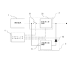
図1で示すものは、本発明の電圧変換回路を具備する電源供給装置の具体的な実施例のデバイス関係図である。本発明の電圧変換回路を具備する電源供給装置は、電源供給装置1、昇圧回路2、降圧回路3及び制御ユニット4からなる。該電源供給装置1が該昇圧回路2に電気的に接続し、且つ該降圧回路3と該昇圧回路2が電気的に並列接続することで、該電源供給装置1が発生した電力はこれを介してデフォルト電圧の電力出力を達成させることができる。 FIG. 1 is a device relationship diagram of a specific embodiment of a power supply apparatus including the voltage conversion circuit of the present invention. The power supply device including the voltage conversion circuit according to the present invention includes a power supply device 1, a booster circuit 2, a step-down circuit 3, and a control unit 4. The power supply device 1 is electrically connected to the booster circuit 2, and the step-down circuit 3 and the booster circuit 2 are electrically connected in parallel, so that the power generated by the power supply device 1 is passed through this. The power output of the default voltage can be achieved.

前述本発明の電圧変換回路を具備する電源供給装置において、該電源供給装置1は電力を供給できる態様のいずれかとすることができる。直接メタノール型燃料電池の具体的な実施例から言うと、これはメタノール燃料と酸素を利用して電気化学反応を行うと共にこれにより直流電力を発生させるものである。該昇圧回路2は直流昇圧変換器21及び第1電気スイッチ22を含み、且つ該直流昇圧変換器21と該第1電気スイッチ22が電気的に直列接続し、該電源供給装置1の出力電力の電圧を比較的高い電圧の電力出力に変換することに用いる。該第1電気スイッチ22は該昇圧回路2の電気伝送ルートのオン或いはオフの選択に用い、且つ該第1電気スイッチ22はダイオードのスイッチング素子、金属酸化膜半導体電界効果トランジスタのスイッチング素子及び電気信号による制御の他電気スイッチング素子の中から選ばれて達成できる。該降圧回路3は直流降圧変換器31及びダイオード32を含み、且つ該直流降圧変換器31と該ダイオード32が電気的に直列接続し、該電源供給装置1の出力電力の電圧を比較的低い電圧の電力出力に変換することに用い、及び該制御ユニット4は参照電圧発生器41と電圧比較器42を含む。該制御ユニット4は該昇圧回路2及び該降圧回路3内のいずれか電圧変換回路を選択して電圧変換を行うことで、該電源供給装置1の出力電力を設定した電圧のある出力電力に調整することに用いる。 In the power supply device including the voltage conversion circuit of the present invention, the power supply device 1 can be any one of the modes that can supply power. Speaking from a specific example of a direct methanol fuel cell, this performs an electrochemical reaction using methanol fuel and oxygen and thereby generates DC power. The booster circuit 2 includes a DC boost converter 21 and a first electrical switch 22, and the DC boost converter 21 and the first electrical switch 22 are electrically connected in series so that the output power of the power supply device 1 can be reduced. Used to convert the voltage to a relatively high voltage power output. The first electric switch 22 is used to select on or off of the electric transmission route of the booster circuit 2, and the first electric switch 22 is a diode switching element, a metal oxide semiconductor field effect transistor switching element, and an electric signal. Other than the control by the electric switching element, it can be selected and achieved. The step-down circuit 3 includes a DC step-down converter 31 and a diode 32, and the DC step-down converter 31 and the diode 32 are electrically connected in series, and the voltage of the output power of the power supply device 1 is set to a relatively low voltage. The control unit 4 includes a reference voltage generator 41 and a voltage comparator 42. The control unit 4 adjusts the output power of the power supply device 1 to a set output power having a set voltage by selecting one of the voltage conversion circuits in the booster circuit 2 and the step-down circuit 3 and performing voltage conversion. Used to do.

前述の制御ユニット4は、参照電圧発生器41と電圧比較器42を含み、該参照電圧発生器41が参照電圧値を提供し、且つ該電圧比較器42は該電源供給装置1の出力電圧と該参照電圧発生器41が提供する参照電圧値を比較し、並びに対応する電気信号を出力することで、該第1電気スイッチ22のオン或いはオフを選択し、またこれにより昇圧回路2または該降圧回路3内のいずれか電圧変換回路を選択して該電源供給装置1の出力電力の電圧変換を行う。 The aforementioned control unit 4 includes a reference voltage generator 41 and a voltage comparator 42, the reference voltage generator 41 provides a reference voltage value, and the voltage comparator 42 is connected to the output voltage of the power supply device 1. The reference voltage value provided by the reference voltage generator 41 is compared, and a corresponding electric signal is output to select whether the first electric switch 22 is turned on or off. One of the voltage conversion circuits in the circuit 3 is selected and voltage conversion of the output power of the power supply device 1 is performed.

前述の該電源供給装置1は、該直流昇圧変換器21と該第1電気スイッチ22が形成する回路に電気的に直列接続する。該直流昇圧変換器21と該第1電気スイッチ22の電気を少なくとも切り換えることができるよう設置するが、該昇圧回路2はやはり等価の機能を具備する。該降圧回路3内の該直流降圧変換器31の一端が該電源供給装置1の電力出力側と電気的に接続し、且つ該直流降圧変換器31の他端が該ダイオード32に電気的に接続する。該ダイオード32と該昇圧回路2の電力出力側が電気的に接続することで、該昇圧回路2が比較的高い電位の電力を出力し、該降圧回路3に入らない。及び該制御ユニット4内部の該電圧比較器42と該第1電気スイッチ22が電気的に接続し、該電圧比較器42の正接点が参照電圧発生器41に接続し、負接点がVin電圧接点43に接続する。該Vin電圧接点43の電圧値と該電源供給装置1の出力電圧が等電位し、該参照電圧発生器41と該Vin電圧接点43との比較を利用して、該電圧比較器42が該第1電気スイッチ22に対してオンとオフの制御を行うことができる。 The aforementioned power supply device 1 is electrically connected in series to the circuit formed by the DC boost converter 21 and the first electrical switch 22. The DC boost converter 21 and the first electric switch 22 are installed so that they can be switched at least, but the booster circuit 2 also has an equivalent function. One end of the DC step-down converter 31 in the step-down circuit 3 is electrically connected to the power output side of the power supply device 1, and the other end of the DC step-down converter 31 is electrically connected to the diode 32. To do. Since the diode 32 and the power output side of the booster circuit 2 are electrically connected, the booster circuit 2 outputs power having a relatively high potential and does not enter the step-down circuit 3. And the voltage comparator 42 in the control unit 4 and the first electrical switch 22 are electrically connected, the positive contact of the voltage comparator 42 is connected to the reference voltage generator 41, and the negative contact is the Vin voltage contact. 43. The voltage value of the Vin voltage contact 43 and the output voltage of the power supply device 1 are equipotential. Using the comparison between the reference voltage generator 41 and the Vin voltage contact 43, the voltage comparator 42 One electrical switch 22 can be turned on and off.

上述の該参照電圧発生器41の出力電圧と該電源供給装置1の出力電圧を比較し、該電圧比較器42を利用して該第1電気スイッチ22に対し制御を行い、該電源供給装置1の出力電圧が該参照電圧発生器41の出力電圧より小さい場合、該第1電気スイッチ22がオンになることで、該昇圧回路2を利用して電圧を上昇させる。逆の場合、該第1電気スイッチ22がオフとなることで、該降圧回路3が該電源供給装置1の電圧を所要電圧値まで降下する。 The output voltage of the reference voltage generator 41 and the output voltage of the power supply device 1 are compared, the first electric switch 22 is controlled using the voltage comparator 42, and the power supply device 1 Is smaller than the output voltage of the reference voltage generator 41, the first electrical switch 22 is turned on, and the voltage is raised using the booster circuit 2. In the opposite case, when the first electrical switch 22 is turned off, the step-down circuit 3 drops the voltage of the power supply device 1 to a required voltage value.

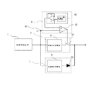
図2に示されるのは、本発明の電圧変換回路を具備する電源供給装置の別の具体的な実施例のデバイス関係図である。前述本発明の実施例に基づき、本発明の電圧変換回路を具備する電源供給装置において、該制御ユニット4の参照電圧発生器41はデジタル−アナログ変換器44とデジタル信号発生器45からなる電圧信号供給装置で代替することができる。 FIG. 2 is a device relationship diagram of another specific example of the power supply apparatus including the voltage conversion circuit of the present invention. In the power supply apparatus having the voltage conversion circuit of the present invention based on the embodiment of the present invention, the reference voltage generator 41 of the control unit 4 is a voltage signal comprising a digital-analog converter 44 and a digital signal generator 45. It can be replaced by a feeding device.

前述制御ユニット4の電圧比較器42の電気信号出力側は、該第1電気スイッチ22に電気的に接続し、且つ該電圧比較器42入力側の正接点が該デジタル−アナログ変換器44に接続する。該デジタル−アナログ変換器44のもう一つ接点が該デジタル信号発生器45に電気的に接続する。該電圧比較器42入力側の負接点がVin電圧接点43に接続し、該Vin電圧接点43の電圧値と該電源供給装置1出力電圧が等電位し、該デジタル信号発生器45を利用してデジタル信号を発生させ、該デジタル−アナログ変換器44を経由して信号を電圧値に変換して該Vin電圧接点43と比較し、Vin電圧接点43電圧の大きさの差異によって該電圧比較器42が該第1電気スイッチ22に対しオンとオフの制御を行う。 The electrical signal output side of the voltage comparator 42 of the control unit 4 is electrically connected to the first electrical switch 22, and the positive contact on the input side of the voltage comparator 42 is connected to the digital-analog converter 44. To do. Another contact of the digital-analog converter 44 is electrically connected to the digital signal generator 45. The negative contact on the input side of the voltage comparator 42 is connected to the Vin voltage contact 43, the voltage value of the Vin voltage contact 43 and the output voltage of the power supply device 1 are equipotential, and the digital signal generator 45 is used. A digital signal is generated, the signal is converted into a voltage value via the digital-analog converter 44 and compared with the Vin voltage contact 43, and the voltage comparator 42 is determined by the difference in the voltage of the Vin voltage contact 43. Controls on and off of the first electrical switch 22.

該デジタル信号発生器45を利用してデジタル信号を発生させ、該デジタル−アナログ変換器44を経由して信号を電圧値に変換してから該電源供給装置1の出力電圧と比較し、該電圧比較器42を利用して該第1電気スイッチ22に対し制御を行い、該電源供給装置1の出力電圧が該参照電圧発生器41の出力電圧より小さい場合、該第1電気スイッチ22がオンになることで、該昇圧回路2を利用して電圧を上昇させる。逆の場合、該第1電気スイッチ22がオフとなることで、該降圧回路3が該電源供給装置1の電圧を所要電圧値まで降下する。 The digital signal generator 45 is used to generate a digital signal, the signal is converted into a voltage value via the digital-analog converter 44, and then compared with the output voltage of the power supply device 1, and the voltage When the comparator 42 is used to control the first electrical switch 22 and the output voltage of the power supply device 1 is smaller than the output voltage of the reference voltage generator 41, the first electrical switch 22 is turned on. Thus, the voltage is raised using the booster circuit 2. In the opposite case, when the first electrical switch 22 is turned off, the step-down circuit 3 drops the voltage of the power supply device 1 to a required voltage value.

図3に示されるのは、本発明の電圧変換回路を具備する電源供給装置の更なる具体的な実施例のデバイス関係図である、これは電源供給装置1、昇圧回路2、降圧回路3及び制御ユニット4からなる。該電源供給装置1が該昇圧回路2に電気的に接続し、且つ該降圧回路3と該昇圧回路2が並列接続し、該電源供給装置1がこの回路を通じて接続し、該電源供給装置1が発生した電力をこれによりデフォルト電圧の電力方式を達成する。 FIG. 3 is a device relationship diagram of a further specific embodiment of the power supply device having the voltage conversion circuit of the present invention, which is a power supply device 1, a booster circuit 2, a step-down circuit 3 and It consists of a control unit 4. The power supply device 1 is electrically connected to the booster circuit 2, the step-down circuit 3 and the booster circuit 2 are connected in parallel, the power supply device 1 is connected through this circuit, and the power supply device 1 The generated power thereby achieves the default voltage power scheme.

前述本発明の電圧変換回路を具備する電源供給装置において、該制御ユニット4は電圧比較器42と電圧出力装置46を含む。該制御ユニット4は該電源供給装置1が該昇圧回路2或いは該降圧回路3で電圧変換するかを選択することに用いる。 In the power supply device having the voltage conversion circuit of the present invention, the control unit 4 includes a voltage comparator 42 and a voltage output device 46. The control unit 4 is used to select whether the power supply device 1 performs voltage conversion in the booster circuit 2 or the step-down circuit 3.

前述の該電源供給装置1は該直流昇圧変換器21と電気的に接続し、該直流昇圧変換器21の他端が該第1電気スイッチ22と電気的に接続し、且つ該直流昇圧変換器21と該第1電気スイッチ22との接続方法の切り換えも該昇圧回路2の働きを達成できる。その他該降圧回路3内の該直流降圧変換器31の一端と該電源供給装置1が電気的に接続し、他端が該ダイオード32に接続する。該制御ユニット4内部の電圧比較器42が該第1電気スイッチ22と電気的に接続し、該電圧比較器42入力側の正接点が電圧出力装置46と電気的に接続する。該電圧比較器42入力側の負接点がVin電圧接点43に電気的に接続し、該Vin電圧接点43の電圧値と該電源供給装置1出力電圧が等電位し、該電圧出力装置46を利用して電圧値を発生して該Vin電圧接点43の電圧と比較し、Vin電圧接点43電圧の大きさによって該電圧比較器42の出力電圧を決定することで該第1電気スイッチ22に対しオンとオフの制御を行う。 The power supply device 1 is electrically connected to the DC boost converter 21, the other end of the DC boost converter 21 is electrically connected to the first electrical switch 22, and the DC boost converter Switching of the connection method between the first electric switch 22 and the first electric switch 22 can also achieve the function of the booster circuit 2. In addition, one end of the DC step-down converter 31 in the step-down circuit 3 and the power supply device 1 are electrically connected, and the other end is connected to the diode 32. A voltage comparator 42 in the control unit 4 is electrically connected to the first electrical switch 22, and a positive contact on the input side of the voltage comparator 42 is electrically connected to a voltage output device 46. The negative contact on the input side of the voltage comparator 42 is electrically connected to the Vin voltage contact 43, the voltage value of the Vin voltage contact 43 and the output voltage of the power supply device 1 are equipotential, and the voltage output device 46 is used. Then, a voltage value is generated and compared with the voltage of the Vin voltage contact 43, and the output voltage of the voltage comparator 42 is determined according to the magnitude of the Vin voltage contact 43 voltage, so that the first electric switch 22 is turned on. And off control.

電圧出力装置46が動的に電圧を発生するため、該電圧と該電源供給装置1の出力電圧を比較し、該電圧比較器42を利用して該第1電気スイッチ22に対し制御を行い、該電源供給装置1の出力電圧が該電圧出力装置46の出力電圧より小さい場合、該第1電気スイッチ22がオンになることで、該昇圧回路2を利用して電圧を上昇させる。逆の場合、該第1電気スイッチ22がオフとなることで、該降圧回路3が該電源供給装置1の電圧を所要電圧値まで降下する。 Since the voltage output device 46 dynamically generates a voltage, the voltage is compared with the output voltage of the power supply device 1 and the first electric switch 22 is controlled using the voltage comparator 42. When the output voltage of the power supply device 1 is smaller than the output voltage of the voltage output device 46, the first electric switch 22 is turned on, and the voltage is increased using the booster circuit 2. In the opposite case, when the first electrical switch 22 is turned off, the step-down circuit 3 drops the voltage of the power supply device 1 to a required voltage value.

図4に示されるのは、本発明の電圧変換回路を具備する電源供給装置の更なる具体的な実施例のデバイス関係図である。本発明の電圧変換回路を具備する電源供給装置は、電源供給装置1、昇圧回路2、降圧回路3及び制御ユニット4からなる。該電源供給装置1が該昇圧回路2に電気的に接続し、且つ該降圧回路3と該昇圧回路2が並列接続し、該電源供給装置1がこの回路を通じて接続し、該電源供給装置1が発生した電力をこれによりデフォルト電圧の電力方式を達成する。 FIG. 4 is a device relationship diagram of a further specific embodiment of the power supply apparatus including the voltage conversion circuit of the present invention. The power supply device including the voltage conversion circuit according to the present invention includes a power supply device 1, a booster circuit 2, a step-down circuit 3, and a control unit 4. The power supply device 1 is electrically connected to the booster circuit 2, the step-down circuit 3 and the booster circuit 2 are connected in parallel, the power supply device 1 is connected through this circuit, and the power supply device 1 The generated power thereby achieves the default voltage power scheme.

前述本発明の電圧変換回路を具備する電源供給装置において、該制御ユニット4は参照電圧発生器41、電圧比較器42、デジタル−アナログ変換器44、デジタル信号発生器45及び電圧調整器48を含む。該制御ユニット4は該電源供給装置1が該昇圧回路2或いは該降圧回路3で電圧変換を行なうかの選択に用いる。 In the power supply apparatus having the voltage conversion circuit of the present invention, the control unit 4 includes a reference voltage generator 41, a voltage comparator 42, a digital-analog converter 44, a digital signal generator 45, and a voltage regulator 48. . The control unit 4 is used to select whether the power supply device 1 performs voltage conversion in the booster circuit 2 or the step-down circuit 3.

前述の該電源供給装置1は該直流昇圧変換器21と電気的に接続し、該直流昇圧変換器21の他端が該第1電気スイッチ22と電気的に接続し、且つ該直流昇圧変換器21と該第1電気スイッチ22との接続方法の切り換えも該昇圧回路2の働きを達成できる。その他該降圧回路3内の該直流降圧変換器31の一端と該電源供給装置1が電気的に接続し、他端が該ダイオード32に接続する。該制御ユニット4内部の電圧比較器42が該第1電気スイッチ22と電気的に接続し、該電圧比較器42入力側の正接点が参照電圧発生器41に電気的に接続し、負接点が該電圧調整器48に接続する。該電圧調整器48のいずれか一端が該デジタル−アナログ変換器44に電気的に接続し、他端が該電源供給装置1の出力電圧に電気的に接続する。該デジタル−アナログ変換器44の他端が該デジタル信号発生器45と電気的に接続し、該デジタル信号発生器45を利用してデジタル信号を発生させ、該デジタル−アナログ変換器44を介して電圧値に変換してから、該電圧調整器48を通じて該参照電圧発生器41の出力電圧と電圧の比較を行うことで、該電圧比較器42該第1電気スイッチ22に対しオンとオフの制御を行う。その他該デジタル信号発生器45が該デジタル−アナログ変換器44を通じて発生した電圧信号は、電気を通じて該直流昇圧変換器21と該直流降圧変換器31に接続するため、該デジタル信号発生器45を介して該直流昇圧変換器21と該直流降圧変換器31の電圧変換状況を制御できる。 The power supply device 1 is electrically connected to the DC boost converter 21, the other end of the DC boost converter 21 is electrically connected to the first electrical switch 22, and the DC boost converter Switching of the connection method between the first electric switch 22 and the first electric switch 22 can also achieve the function of the booster circuit 2. In addition, one end of the DC step-down converter 31 in the step-down circuit 3 and the power supply device 1 are electrically connected, and the other end is connected to the diode 32. A voltage comparator 42 in the control unit 4 is electrically connected to the first electrical switch 22, a positive contact on the input side of the voltage comparator 42 is electrically connected to a reference voltage generator 41, and a negative contact is Connect to the voltage regulator 48. One end of the voltage regulator 48 is electrically connected to the digital-analog converter 44, and the other end is electrically connected to the output voltage of the power supply device 1. The other end of the digital-analog converter 44 is electrically connected to the digital signal generator 45, generates a digital signal using the digital signal generator 45, and passes through the digital-analog converter 44. After the voltage value is converted, the output voltage of the reference voltage generator 41 is compared with the voltage through the voltage regulator 48 to control the voltage comparator 42 to turn on and off the first electrical switch 22. I do. In addition, the voltage signal generated by the digital signal generator 45 through the digital-analog converter 44 is connected to the DC step-up converter 21 and the DC step-down converter 31 through electricity. Thus, the voltage conversion status of the DC step-up converter 21 and the DC step-down converter 31 can be controlled.

該デジタル信号発生器45を利用してデジタル信号を発生させ、該デジタル−アナログ変換器44と該電圧調整器48を経由して信号を電圧値に変換して該参照電圧発生器41の出力電圧と電圧の比較を行う。該電圧比較器42を利用して該第1電気スイッチ22に対して制御を行い、該デジタル信号発生器45が発生した信号は該デジタル−アナログ変換器44と該電圧調整器48を経由して変換した後の出力電圧が該参照電圧発生器41の出力電圧より小さい場合、該第1電気スイッチ22がオンになることで、該電源供給装置1の出力電力が該昇圧回路2を通じて電圧を上昇させる。逆の場合、該第1電気スイッチ22がオフとなることで、該降圧回路3が該電源供給装置1の電圧を所要電圧値まで降下する。該デジタル信号発生器45が動的にそのデジタル信号の発生を調整するため、該電源供給装置1の電圧変換を動的に調整することを達成できる。 The digital signal generator 45 is used to generate a digital signal, the signal is converted into a voltage value via the digital-analog converter 44 and the voltage regulator 48, and the output voltage of the reference voltage generator 41 is converted. And compare the voltage. The voltage comparator 42 is used to control the first electrical switch 22, and the signal generated by the digital signal generator 45 passes through the digital-analog converter 44 and the voltage regulator 48. When the output voltage after conversion is smaller than the output voltage of the reference voltage generator 41, the first electric switch 22 is turned on, so that the output power of the power supply device 1 increases the voltage through the booster circuit 2. Let In the opposite case, when the first electrical switch 22 is turned off, the step-down circuit 3 drops the voltage of the power supply device 1 to a required voltage value. Since the digital signal generator 45 dynamically adjusts the generation of the digital signal, the voltage conversion of the power supply device 1 can be adjusted dynamically.

図5に示されるものは、本発明の電圧変換回路を具備する電源供給装置の更なる具体的な実施例のデバイス関係図である。本発明の電圧変換回路を具備する電源供給装置は、電源供給装置1、昇圧回路2、降圧回路3及び制御ユニット4からなる。該電源供給装置1が該昇圧回路2に電気的に接続し、且つ該降圧回路3と該昇圧回路2が並列接続し、該電源供給装置1がこの回路を通じて接続し、該電源供給装置1が発生した電力をこれによりデフォルト電圧の電力方式を達成する。 What is shown in FIG. 5 is a device relationship diagram of a further specific embodiment of the power supply apparatus including the voltage conversion circuit of the present invention. The power supply device including the voltage conversion circuit according to the present invention includes a power supply device 1, a booster circuit 2, a step-down circuit 3, and a control unit 4. The power supply device 1 is electrically connected to the booster circuit 2, the step-down circuit 3 and the booster circuit 2 are connected in parallel, the power supply device 1 is connected through this circuit, and the power supply device 1 The generated power thereby achieves the default voltage power scheme.

前述本発明の電圧変換回路を具備する電源供給装置において、該制御ユニット4は参照電圧発生器41、電圧比較器42、電圧出力装置46と電圧調整器48を含む。該制御ユニット4は該電源供給装置1が該昇圧回路2或いは該降圧回路3で電圧変換を行うかの選択に用いる。 In the power supply apparatus having the voltage conversion circuit of the present invention, the control unit 4 includes a reference voltage generator 41, a voltage comparator 42, a voltage output apparatus 46, and a voltage regulator 48. The control unit 4 is used to select whether the power supply device 1 performs voltage conversion in the booster circuit 2 or the step-down circuit 3.

前述の該電源供給装置1は該直流昇圧変換器21と電気的に接続し、該直流昇圧変換器21の他端が該第1電気スイッチ22と電気的に接続し、且つ該直流昇圧変換器21と該第1電気スイッチ22との接続方法の切り換えも該昇圧回路2の働きを達成できる。その他該降圧回路3内の該直流降圧変換器31の一端と該電源供給装置1が電気的に接続し、他端が該ダイオード32に電気的に接続する。該制御ユニット4内部の電圧比較器42が該第1電気スイッチ22と電気的に接続し、該電圧比較器42入力側の正接点が参照電圧発生器41に電気的に接続し、該電圧比較器42入力側の負接点が該電圧調整器48に電気的に接続する。該電圧調整器48のいずれか一端が該電圧出力装置46と電気的に接続し、他端が該電源供給装置1の出力電圧に電気的に接続し、該電圧出力装置46が発生した電圧は該電圧調整器48と該参照電圧発生器41の出力電圧を通じて電圧の比較を行い、該電圧比較器42が比較結果により該第1電気スイッチ22をオン状態或いはオフ状態にすることを選択することで、更に該直流昇圧変換器21或いは該直流降圧変換器31を選択して電圧変換を行い、並びに該電圧出力装置46が出力した電力の電圧変換を制御できる。 The power supply device 1 is electrically connected to the DC boost converter 21, the other end of the DC boost converter 21 is electrically connected to the first electrical switch 22, and the DC boost converter Switching of the connection method between the first electric switch 22 and the first electric switch 22 can also achieve the function of the booster circuit 2. In addition, one end of the DC step-down converter 31 in the step-down circuit 3 and the power supply device 1 are electrically connected, and the other end is electrically connected to the diode 32. A voltage comparator 42 in the control unit 4 is electrically connected to the first electrical switch 22, and a positive contact on the input side of the voltage comparator 42 is electrically connected to a reference voltage generator 41. The negative contact on the input side of the regulator 42 is electrically connected to the voltage regulator 48. One end of the voltage regulator 48 is electrically connected to the voltage output device 46, the other end is electrically connected to the output voltage of the power supply device 1, and the voltage generated by the voltage output device 46 is The voltage is compared through the output voltage of the voltage regulator 48 and the reference voltage generator 41, and the voltage comparator 42 selects to turn on or off the first electrical switch 22 according to the comparison result. Thus, the DC step-up converter 21 or the DC step-down converter 31 is further selected to perform voltage conversion, and the voltage conversion of the power output from the voltage output device 46 can be controlled.

前述の実施例において、該電圧出力装置46が発生した電圧を利用し、更に該電圧調整器48と該参照電圧発生器41の出力電圧を通じて電圧の比較を行い、該電圧比較器42が該第1電気スイッチ22を制御できる。これにより、該電圧出力装置46の出力電圧は更に該電圧調整器48を通じて変換した電圧が該参照電圧発生器41の出力電圧より小さい場合、該第1電気スイッチ22がオンになることで、該昇圧回路2を利用して電圧を上昇させる。逆の場合、該第1電気スイッチ22がオフとなることで、該降圧回路3が該電源供給装置1の電圧を所要電圧値まで降下する。該電圧出力装置46が動的にその電圧値を調整できるため、該電源供給装置1の電圧変換を動的に調整することを達成できる。 In the above-described embodiment, the voltage generated by the voltage output device 46 is used to compare the voltages through the output voltages of the voltage regulator 48 and the reference voltage generator 41, and the voltage comparator 42 1 The electric switch 22 can be controlled. Accordingly, when the voltage converted through the voltage regulator 48 is smaller than the output voltage of the reference voltage generator 41, the output voltage of the voltage output device 46 is turned on by the first electrical switch 22 being turned on. The voltage is raised using the booster circuit 2. In the opposite case, when the first electrical switch 22 is turned off, the step-down circuit 3 drops the voltage of the power supply device 1 to a required voltage value. Since the voltage output device 46 can dynamically adjust the voltage value, the voltage conversion of the power supply device 1 can be adjusted dynamically.

図6に示されるものは、本発明の電圧変換回路を具備する電源供給装置の更なる具体的な実施例のデバイス関係図である。本発明の電圧変換回路を具備する電源供給装置は、電源供給装置1、昇圧回路2、降圧回路3及びマイクロコントロールユニット47からなる。該電源供給装置1が該昇圧回路2に電気的に接続し、且つ該降圧回路3と該昇圧回路2が並列接続し、該電源供給装置1がこの回路を通じて接続し、該電源供給装置1が発生した電力をこれによりデフォルト電圧の電力方式を達成する。 What is shown in FIG. 6 is a device relationship diagram of a further specific embodiment of the power supply apparatus including the voltage conversion circuit of the present invention. The power supply device including the voltage conversion circuit of the present invention includes a power supply device 1, a booster circuit 2, a step-down circuit 3, and a micro control unit 47. The power supply device 1 is electrically connected to the booster circuit 2, the step-down circuit 3 and the booster circuit 2 are connected in parallel, the power supply device 1 is connected through this circuit, and the power supply device 1 The generated power thereby achieves the default voltage power scheme.

前述の該電源供給装置1は該直流昇圧変換器21と電気的に接続し、該直流昇圧変換器21の他端が該第1電気スイッチ22と電気的に接続し、且つ該第1電気スイッチ22と該直流昇圧変換器21との接続方法の切り換えも該昇圧回路2の働きを達成できる。該降圧回路3内の該直流降圧変換器31の一端と該電源供給装置1が電気的に接続し、他端が該ダイオード32に接続する。及び該マイクロコントロールユニット47が該昇圧回路2の第1電気スイッチ22と電気的に接続し、並びにマイクロコントロールユニット47を通じて電気信号を発することで該第1電気スイッチ22の作動を制御できる。 The power supply device 1 is electrically connected to the DC boost converter 21, the other end of the DC boost converter 21 is electrically connected to the first electrical switch 22, and the first electrical switch. Switching of the connection method between the step-up converter 22 and the DC step-up converter 21 can also achieve the function of the step-up circuit 2. One end of the DC step-down converter 31 in the step-down circuit 3 and the power supply device 1 are electrically connected, and the other end is connected to the diode 32. The micro control unit 47 is electrically connected to the first electric switch 22 of the booster circuit 2, and the operation of the first electric switch 22 can be controlled by generating an electric signal through the micro control unit 47.

該システムのデフォルト電圧の要求が該電源供給装置1の出力電圧より高い時、該マイクロコントロールユニット47は該昇圧回路2の該第1電気スイッチ22が該昇圧回路2のオンを選択することを制御すると、該電源供給装置1の出力電力は該昇圧回路2を通じて電圧変換を行い、システムが要求する電圧の電力を出力できる。及びシステムのデフォルト電圧の要求が該電源供給装置1の出力電圧より低い時、該マイクロコントロールユニット47は該昇圧回路2の該第1電気スイッチ22が該昇圧回路2のオフを選択することを制御すると、該電源供給装置1の出力電力が該降圧回路3を通じて電圧変換を行い、システムが要求する電圧の電力を出力できる。 When the default voltage requirement of the system is higher than the output voltage of the power supply device 1, the micro control unit 47 controls that the first electrical switch 22 of the booster circuit 2 selects the booster circuit 2 to be turned on. Then, the output power of the power supply device 1 undergoes voltage conversion through the booster circuit 2 and can output the power of the voltage required by the system. When the default voltage requirement of the system is lower than the output voltage of the power supply device 1, the micro control unit 47 controls that the first electrical switch 22 of the booster circuit 2 selects the booster circuit 2 to be turned off. Then, the output power of the power supply device 1 performs voltage conversion through the step-down circuit 3 and can output the power of the voltage required by the system.

図7に示されるものは、本発明の電圧変換回路を具備する電源供給装置の更なる具体的な実施例のデバイス関係図である。本発明の電圧変換回路を具備する電源供給装置は、電源供給装置1、昇圧回路2、降圧回路3、制御ユニット4及び逆変換器5からなる。該電源供給装置1が該昇圧回路2に電気的に接続し、且つ該降圧回路3と該昇圧回路2が並列接続し、該電源供給装置1がこの回路を通じて接続し、該電源供給装置1が発生した電力をこれによりデフォルト電圧の電力方式を達成する。 What is shown in FIG. 7 is a device relationship diagram of a further specific embodiment of the power supply apparatus including the voltage conversion circuit of the present invention. The power supply device including the voltage conversion circuit of the present invention includes a power supply device 1, a booster circuit 2, a step-down circuit 3, a control unit 4, and an inverse converter 5. The power supply device 1 is electrically connected to the booster circuit 2, the step-down circuit 3 and the booster circuit 2 are connected in parallel, the power supply device 1 is connected through this circuit, and the power supply device 1 The generated power thereby achieves the default voltage power scheme.

前述の該電源供給装置1は該直流昇圧変換器21と電気的に接続し、該直流昇圧変換器21の他端が該第1電気スイッチ22と電気的に接続し、且つ該直流昇圧変換器21と該第1電気スイッチ22との接続方法の切り換えも該昇圧回路2の働きを達成できる。該降圧回路3内の該直流降圧変換器31の一端と該電源供給装置1が電気的に接続し、該直流降圧変換器31の他端が第2電気スイッチ33に電気的に接続する。該制御ユニット4内部の電圧比較器42が該第1電気スイッチ22と電気的に接続し、該電圧比較器42の出力側が該逆変換器5に電気的に接続し、並びに更に該逆変換器5を通じて該第2電気スイッチ33の制御側に電気的に接続する。該電圧比較器42の入力側の正接点が参照電圧発生器41に電気的に接続し、該電圧比較器42の入力側の負接点がVin電圧接点43に接続し、該Vin電圧接点43の電圧値と該電源供給装置1の出力電圧が等電位し、該参照電圧発生器41の出力電圧と該Vin電圧接点43の比較を通じ、該電圧比較器42が正方向及び逆方向の信号を出力することで該第1電気スイッチ22をオン或いはオフ状態とし、且つ該第2電気スイッチ33が該第1電気スイッチ22と逆の状態となることを各々選択する。 The power supply device 1 is electrically connected to the DC boost converter 21, the other end of the DC boost converter 21 is electrically connected to the first electrical switch 22, and the DC boost converter Switching of the connection method between the first electric switch 22 and the first electric switch 22 can also achieve the function of the booster circuit 2. One end of the DC step-down converter 31 in the step-down circuit 3 and the power supply device 1 are electrically connected, and the other end of the DC step-down converter 31 is electrically connected to the second electrical switch 33. A voltage comparator 42 in the control unit 4 is electrically connected to the first electrical switch 22, an output side of the voltage comparator 42 is electrically connected to the inverse converter 5, and further, the inverse converter 5 is electrically connected to the control side of the second electrical switch 33. The positive contact on the input side of the voltage comparator 42 is electrically connected to the reference voltage generator 41, the negative contact on the input side of the voltage comparator 42 is connected to the Vin voltage contact 43, and the Vin voltage contact 43 A voltage value and the output voltage of the power supply device 1 are equipotential, and the voltage comparator 42 outputs signals in the forward and reverse directions through a comparison of the output voltage of the reference voltage generator 41 and the Vin voltage contact 43. Thus, the first electrical switch 22 is turned on or off, and the second electrical switch 33 is selected to be in the opposite state to the first electrical switch 22.

前述の該参照電圧発生器41の出力電圧と該電源供給装置1の出力電圧の比較を利用し、且つ該電圧比較器42を通じて該第1電気スイッチ22と該第2電気スイッチ33を制御する。これにより、該電源供給装置1の出力電圧が該参照電圧発生器41の出力電圧より小さい場合、該電圧比較器42が出力した電気信号は該第1電気スイッチ22をオン状態に選択し、同時に該電気信号が該逆変換器5を通じて逆位相信号となって該第2電気スイッチ33をオフ状態になるよう選択することで、該昇圧回路2の作動により、該電源供給装置1の出力電力の電圧を定格電圧にまで上昇する。別の面で、該電源供給装置1の出力電圧が該参照電圧発生器41の出力電圧より大きくなった場合、該電圧比較器42が出力した電気信号は該第1電気スイッチ22をオフ状態になるよう選択し、同時に該電気信号が該逆変換器5を通じて逆位相信号となって該第2電気スイッチ33をオン状態に選択することで、該降圧回路3の作動を通じ、該電源供給装置1の出力電力の電圧を定格電圧にまで降下する。 The first electric switch 22 and the second electric switch 33 are controlled through the voltage comparator 42 using the comparison between the output voltage of the reference voltage generator 41 and the output voltage of the power supply device 1 described above. As a result, when the output voltage of the power supply device 1 is smaller than the output voltage of the reference voltage generator 41, the electrical signal output from the voltage comparator 42 selects the first electrical switch 22 in the ON state, and at the same time By selecting the second electric switch 33 to be in an OFF state, the electric signal becomes a reverse phase signal through the inverse converter 5, so that the output power of the power supply device 1 is controlled by the operation of the booster circuit 2. Increase the voltage to the rated voltage. In another aspect, when the output voltage of the power supply device 1 becomes larger than the output voltage of the reference voltage generator 41, the electrical signal output from the voltage comparator 42 turns the first electrical switch 22 off. At the same time, the electric signal becomes an antiphase signal through the inverse converter 5 and the second electric switch 33 is selected to be in an ON state, so that the power supply device 1 is activated through the operation of the step-down circuit 3. Reduce the output power voltage to the rated voltage.

図8に示されるものは、本発明の電圧変換回路を具備する電源供給装置の更なる具体的な実施例のデバイス関係図である。本発明の電圧変換回路を具備する電源供給装置は、電源供給装置1、昇圧回路2、降圧回路3、制御ユニット4及び逆変換器5からなる。該電源供給装置1が該昇圧回路2に電気的に接続し、且つ該降圧回路3と該昇圧回路2が並列接続し、該電源供給装置1がこの回路を通じて接続し、該電源供給装置1が発生した電力をこれによりデフォルト電圧の電力方式を達成する。 What is shown in FIG. 8 is a device relationship diagram of a further specific embodiment of the power supply apparatus including the voltage conversion circuit of the present invention. The power supply device including the voltage conversion circuit of the present invention includes a power supply device 1, a booster circuit 2, a step-down circuit 3, a control unit 4, and an inverse converter 5. The power supply device 1 is electrically connected to the booster circuit 2, the step-down circuit 3 and the booster circuit 2 are connected in parallel, the power supply device 1 is connected through this circuit, and the power supply device 1 The generated power thereby achieves the default voltage power scheme.

前述の該昇圧回路2は、直流昇圧変換器21及び電気スイッチ22を含む。該降圧回路3が直流降圧変換器31及び背合わせ(back-to-back)接続の金属酸化膜半導体の電気スイッチセット34を含み、該背合わせ接続の金属酸化膜半導体の電気スイッチセット34が2個の金属酸化膜半導体の電気スイッチが電気的に直列接続し、且つ2個の金属酸化膜半導体の電気スイッチの寄生ダイオードの方向が逆となり、これにより該背合わせ接続の金属酸化膜半導体の電気スイッチセット34を通じて関閉該降圧回路3の作動をオフにすることができると共に有効的に逆電流の発生を防止できる。 The booster circuit 2 described above includes a DC boost converter 21 and an electrical switch 22. The step-down circuit 3 includes a DC step-down converter 31 and a back-to-back connected metal oxide semiconductor electrical switch set 34, and the back-to-back connected metal oxide semiconductor electrical switch set 34 includes 2 The two metal oxide semiconductor electrical switches are electrically connected in series, and the direction of the parasitic diodes of the two metal oxide semiconductor electrical switches is reversed. It is possible to turn off the operation of the step-down circuit 3 through the switch set 34 and effectively prevent the generation of a reverse current.

前述の該電源供給装置1は該直流昇圧変換器21と電気的に接続し、該直流昇圧変換器21の他端が該第1電気スイッチ22と電気的に接続し、且つ該直流昇圧変換器21と該第1電気スイッチ22との接続方法の切り換えも該昇圧回路2の働きを達成できる。該降圧回路3内の該直流降圧変換器31の一端が該電源供給装置1と電気的に接続し、該直流降圧変換器31の他端が該背合わせ接続の金属酸化膜半導体の電気スイッチセット34に電気的に接続する。該制御ユニット4内部の電圧比較器42と該第1電気スイッチ22が電気的に接続する。その他該電圧比較器42の出力側が該逆変換器5に接続し、該逆変換器5を通じて該背合わせ接続の金属酸化膜半導体の電気スイッチセット34に電気的に接続する。該電圧比較器42の正接点が参照電圧発生器41に接続し、負接点がVin電圧接点43に接続し、該Vin電圧接点43の電圧値と該電源供給装置1の出力電圧が等電位し、該参照電圧発生器41の出力電圧と該Vin電圧接点43の比較を利用し、該電圧比較器42が該第1電気スイッチ22と該背合わせ接続の金属酸化膜半導体の電気スイッチセット34に対してオンとオフの制御を行う。 The power supply device 1 is electrically connected to the DC boost converter 21, the other end of the DC boost converter 21 is electrically connected to the first electrical switch 22, and the DC boost converter Switching of the connection method between the first electric switch 22 and the first electric switch 22 can also achieve the function of the booster circuit 2. One end of the DC step-down converter 31 in the step-down circuit 3 is electrically connected to the power supply device 1, and the other end of the DC step-down converter 31 is a back-to-back metal oxide semiconductor electrical switch set. 34 is electrically connected. The voltage comparator 42 in the control unit 4 and the first electric switch 22 are electrically connected. In addition, the output side of the voltage comparator 42 is connected to the inverse converter 5, and is electrically connected to the back-to-back metal oxide semiconductor switch 34 through the inverter 5. The positive contact of the voltage comparator 42 is connected to the reference voltage generator 41, the negative contact is connected to the Vin voltage contact 43, and the voltage value of the Vin voltage contact 43 and the output voltage of the power supply device 1 are equipotential. Using the comparison between the output voltage of the reference voltage generator 41 and the Vin voltage contact 43, the voltage comparator 42 is connected to the first electrical switch 22 and the back-connected metal oxide semiconductor electrical switch set 34. On and off control is performed.

前述の該電圧比較器42を利用して該参照電圧発生器41の出力電圧と該電源供給装置1の出力電圧を比較し、且つ該電圧比較器42は該第1電気スイッチ22と該背合わせ接続の金属酸化膜半導体の電気スイッチセット34を制御できる。該電源供給装置1の出力電圧が該参照電圧発生器41の出力電圧より小さい場合、該参照電圧発生器41が電気信号を出力して該第1電気スイッチ22をオン状態になるよう選択し、且つ該電気信号も該逆変換器5を通じて逆位相信号を形成し、且つ逆位相信号が該背合わせ接続の金属酸化膜半導体の電気スイッチセット34をオフ状態になるよう選択することで、該昇圧回路2の作動を通じて、該電源供給装置1の出力電力の電圧を定格電圧にまで上昇する。別の面において、該電源供給装置1の出力電圧が該参照電圧発生器41の出力電圧より大きい場合、該参照電圧発生器41が電気信号を出力して該第1電気スイッチ22をオフ状態になるよう選択し、且つ該電気信号も該逆変換器5を通じて逆位相信号を形成し、且つ逆位相信号が該背合わせ接続の金属酸化膜半導体の電気スイッチセット34をオン状態になるよう選択することで、該降圧回路3の作動を通じ、該電源供給装置1の出力電力の電圧を定格電圧にまで降下する。 The voltage comparator 42 is used to compare the output voltage of the reference voltage generator 41 and the output voltage of the power supply device 1, and the voltage comparator 42 is back-to-back with the first electrical switch 22. The electrical switch set 34 of the connected metal oxide semiconductor can be controlled. When the output voltage of the power supply device 1 is smaller than the output voltage of the reference voltage generator 41, the reference voltage generator 41 outputs an electrical signal and selects the first electrical switch 22 to be turned on, In addition, the electric signal also forms an antiphase signal through the inverse converter 5, and the antiphase signal selects the electric switch set 34 of the back-to-back metal oxide semiconductor to turn off the boosting step. Through the operation of the circuit 2, the voltage of the output power of the power supply device 1 is increased to the rated voltage. In another aspect, when the output voltage of the power supply device 1 is greater than the output voltage of the reference voltage generator 41, the reference voltage generator 41 outputs an electrical signal to turn off the first electrical switch 22. And the electrical signal also forms an antiphase signal through the inverse converter 5, and the antiphase signal selects the electrical switch set 34 of the back-to-back metal oxide semiconductor to be in an ON state. Thus, the voltage of the output power of the power supply device 1 is lowered to the rated voltage through the operation of the step-down circuit 3.

以上本発明につき好適な実施例を挙げて種々説明したが、本発明はこの具体的な実施例に限定されるものではなく、本発明の精神を逸脱しない範囲内において種々の改良変更をなし得ることは、添付されている特許請求の範囲内に含めるものであるのが勿論である。 Although the present invention has been described in detail with reference to preferred embodiments, the present invention is not limited to these specific embodiments, and various improvements and modifications can be made without departing from the spirit of the present invention. Is, of course, included within the scope of the appended claims.

本発明の電圧変換回路を具備する電源供給装置の具体的な実施例のデバイス関係図である。FIG. 3 is a device relationship diagram of a specific example of a power supply device including the voltage conversion circuit of the present invention. 本発明の電圧変換回路を具備する電源供給装置の別の具体的な実施例のデバイス関係図である。It is a device related figure of another specific Example of the power supply device which comprises the voltage conversion circuit of this invention. 本発明の電圧変換回路を具備する電源供給装置の更なる具体的な実施例のデバイス関係図である。FIG. 6 is a device relationship diagram of a further specific example of a power supply device including the voltage conversion circuit of the present invention. 本発明の電圧変換回路を具備する電源供給装置の更なる具体的な実施例のデバイス関係図である。FIG. 6 is a device relationship diagram of a further specific example of a power supply device including the voltage conversion circuit of the present invention. 本発明の電圧変換回路を具備する電源供給装置の更なる具体的な実施例のデバイス関係図である。FIG. 6 is a device relationship diagram of a further specific example of a power supply device including the voltage conversion circuit of the present invention. 本発明の電圧変換回路を具備する電源供給装置の更なる具体的な実施例のデバイス関係図である。FIG. 6 is a device relationship diagram of a further specific example of a power supply device including the voltage conversion circuit of the present invention. 本発明の電圧変換回路を具備する電源供給装置の更なる具体的な実施例のデバイス関係図、及び、FIG. 5 is a device relationship diagram of a further specific embodiment of the power supply apparatus including the voltage conversion circuit of the present invention; 本発明の電圧変換回路を具備する電源供給装置の更なる具体的な実施例のデバイス関係図である。FIG. 6 is a device relationship diagram of a further specific example of a power supply device including the voltage conversion circuit of the present invention.

符号の説明Explanation of symbols

1 電源供給装置
2 昇圧回路
3 降圧回路
4 制御ユニット
5 逆変換器
21 直流昇圧変換器
22 第1電気スイッチ
31 直流降圧変換器
32 ダイオード
33 第2電気スイッチ
34 背合わせ接続の金属酸化膜半導体の電気スイッチセット
41 参照電圧発生器
42 電圧比較器
43 Vin電圧接点
44 デジタル−アナログ変換器
45 デジタル信号発生器
46 電圧出力装置
47 マイクロコントロールユニット
48 電圧調整器
DESCRIPTION OF SYMBOLS 1 Power supply device 2 Booster circuit 3 Buck circuit 4 Control unit 5 Inverter 21 DC boost converter 22 1st electric switch 31 DC buck converter 32 Diode
33 Second electrical switch 34 Back-to-back metal oxide semiconductor electrical switch set
41 Reference Voltage Generator 42 Voltage Comparator 43 Vin Voltage Contact 44 Digital-Analog Converter 45 Digital Signal Generator 46 Voltage Output Device 47 Micro Control Unit 48 Voltage Regulator

Claims (15)

電圧変換回路を具備する電源供給装置であって、
各種電力供給方式とすることができる電源供給装置と、
直流昇圧変換器と電気スイッチを含み、前記直流昇圧変換器が前記電気スイッチに電気的に直列接続し、且つ、前記直流昇圧変換器が入力電力の電圧を上昇させる昇圧回路と、
直流降圧変換器とダイオードを含み、前記直流降圧変換器が前記ダイオードに電気的に直列接続し、且つ、前記直流降圧変換器が入力電力の電圧を降下させる降圧回路、及び、
前記電源供給装置が前記昇圧回路、或いは、前記降圧電気回で電圧変換を行うかの選択に用いる制御ユニットを含み、
前記昇圧回路と前記降圧回路が電気的に並列接続し、前記制御ユニットが前記昇圧回路の電気スイッチに電気的に接続し、並びに、前記制御ユニットが前記昇圧回路のオン状態、または、オフ状態のいずれかの状態になるよう選択することを特徴とする、電圧変換回路を具備する電源供給装置。
A power supply device comprising a voltage conversion circuit,
A power supply device capable of various power supply methods;
A boosting circuit including a DC boost converter and an electrical switch, wherein the DC boost converter is electrically connected in series to the electrical switch, and the DC boost converter increases the voltage of input power;
A step-down circuit including a DC step-down converter and a diode, the DC step-down converter being electrically connected in series to the diode, and the DC step-down converter dropping a voltage of input power; and
A control unit used to select whether the power supply device performs voltage conversion in the booster circuit or the step-down electrical circuit;
The step-up circuit and the step-down circuit are electrically connected in parallel, the control unit is electrically connected to an electric switch of the step-up circuit, and the control unit is in an on state or an off state of the step-up circuit. A power supply device comprising a voltage conversion circuit, wherein the power supply device is selected to be in any state.
請求項1記載の電圧変換回路を具備する電源供給装置において、前記制御ユニットは、電圧比較器と参照電圧発生器を更に含み、前記電圧比較器の入力側が前記参照電圧発生器に電気的に接続し、前記電圧比較器の別の入力側が前記電源供給装置の出力側に電気的に接続し、前記制御ユニットの電圧比較器の電気信号出力側が前記電気スイッチの制御側に電気的に接続し、並びに、前記電気スイッチをオン状態、または、オフ状態のいずれかの状態になるよう選択し、且つ、前記昇圧回路がオン状態、または、オフ状態のいずれかの状態に対応することを特徴とする、電圧変換回路を具備する電源供給装置。 2. The power supply apparatus comprising the voltage conversion circuit according to claim 1, wherein the control unit further includes a voltage comparator and a reference voltage generator, and an input side of the voltage comparator is electrically connected to the reference voltage generator. And another input side of the voltage comparator is electrically connected to an output side of the power supply device, and an electric signal output side of the voltage comparator of the control unit is electrically connected to a control side of the electric switch, In addition, the electrical switch is selected to be in an on state or an off state, and the booster circuit corresponds to either the on state or the off state. A power supply device comprising a voltage conversion circuit. 請求項2記載の電圧変換回路を具備する電源供給装置において、前記電気スイッチが金属酸化膜半導体スイッチング素子で、且つ、前記制御ユニットは前記電気スイッチのゲート電極側に電気的に接続することを特徴とする、電圧変換回路を具備する電源供給装置。 3. The power supply device comprising the voltage conversion circuit according to claim 2, wherein the electrical switch is a metal oxide semiconductor switching element, and the control unit is electrically connected to a gate electrode side of the electrical switch. A power supply device including a voltage conversion circuit. 請求項1記載の電圧変換回路を具備する電源供給装置において、前記制御ユニットはデジタル信号発生器とデジタル−アナログ変換器を更に含み、前記デジタル信号発生器はデジタル信号発生装置で、且つ、前記デジタル信号発生器が前記デジタル−アナログ変換器の入力側に電気的に接続し、及び、前記デジタル−アナログ変換器はデジタル信号をアナログ信号に変換する装置で、且つ、前記デジタル−アナログ変換器の出力側が前記電圧比較器に電気的に接続し、前記電源供給装置の出力電圧と比較に用いるため、参照電圧を提供することを特徴とする、電圧変換回路を具備する電源供給装置。 2. The power supply apparatus comprising the voltage conversion circuit according to claim 1, wherein the control unit further includes a digital signal generator and a digital-analog converter, and the digital signal generator is a digital signal generator and the digital signal generator. A signal generator is electrically connected to an input side of the digital-analog converter, and the digital-analog converter is a device for converting a digital signal into an analog signal, and an output of the digital-analog converter A power supply device comprising a voltage conversion circuit, wherein a side is electrically connected to the voltage comparator and provides a reference voltage for comparison with the output voltage of the power supply device. 請求項1記載の電圧変換回路を具備する電源供給装置において、前記制御ユニットはパルス信号発生装置とパルス信号の電圧信号変換回路を更に含み、前記パルス信号発生装置は特定動作周期のあるパルス信号を発生する電気装置、及び、前記パルス信号の電圧信号変換回路はパルス信号を電圧の電気信号に変換する装置、且つ、前記パルス信号の電圧信号変換回路が出力した電圧の電気信号が前記パルス信号発生装置のパルス信号に対応することを特徴とする、電圧変換回路を具備する電源供給装置。 2. The power supply apparatus comprising the voltage conversion circuit according to claim 1, wherein the control unit further includes a pulse signal generation device and a pulse signal voltage signal conversion circuit, and the pulse signal generation device receives a pulse signal having a specific operation cycle. An electric device for generating the voltage signal conversion circuit for the pulse signal is a device for converting the pulse signal into an electric signal for voltage, and the electric signal of the voltage output from the voltage signal conversion circuit for the pulse signal is the pulse signal generation A power supply device comprising a voltage conversion circuit, which corresponds to a pulse signal of the device. 請求項5記載の電圧変換回路を具備する電源供給装置において、前記制御ユニットの電圧出力装置内のパルス信号の電圧信号変更回路は、電圧フォロワを含むことを特徴とする、電圧変換回路を具備する電源供給装置。 6. The power supply apparatus comprising the voltage conversion circuit according to claim 5, wherein the voltage signal change circuit for the pulse signal in the voltage output apparatus of the control unit includes a voltage follower. Power supply device. 請求項1記載の電圧変換回路を具備する電源供給装置において、前記制御ユニットは、デジタル信号発生器、デジタル−アナログ変換器、及び、電圧調整器を更に含み、前記デジタル信号発生器が前記デジタル−アナログ変換器を通じて電気信号を発生させて前記電圧調整器を制御し、また、前記電源供給装置が出力した電圧信号は前記電圧調整器を経由して出力した電圧と前記参照電圧発生器の出力電圧を前記電圧比較器により判断することを特徴とする、電圧変換回路を具備する電源供給装置。 2. The power supply apparatus comprising the voltage conversion circuit according to claim 1, wherein the control unit further includes a digital signal generator, a digital-analog converter, and a voltage regulator, wherein the digital signal generator is the digital- The voltage regulator is controlled by generating an electrical signal through an analog converter, and the voltage signal output from the power supply device includes the voltage output via the voltage regulator and the output voltage of the reference voltage generator. A power supply device comprising a voltage conversion circuit, wherein the voltage comparator determines the above. 請求項7記載の電圧変換回路を具備する電源供給装置において、前記デジタル−アナログ変換器は前記昇圧回路の直流昇圧変換器と前記降圧回路の直流降圧変換器に電気的に接続し、且つ、前記デジタル信号発生器の前記デジタル−アナログ変換器を経由して発生した電気信号により、前記直流昇圧変換器と前記直流降圧変換器の作動を制御することを特徴とする、電圧変換回路を具備する電源供給装置。 8. The power supply apparatus comprising the voltage conversion circuit according to claim 7, wherein the digital-analog converter is electrically connected to a direct current step-up converter of the step-up circuit and a direct-current step-down converter of the step-down circuit, and A power supply comprising a voltage conversion circuit, wherein the operation of the DC step-up converter and the DC step-down converter is controlled by an electrical signal generated via the digital-analog converter of a digital signal generator Feeding device. 請求項1記載の電圧変換回路を具備する電源供給装置において、前記制御ユニットは電圧出力装置と電圧調整器を更に含み、前記電圧出力装置が電気信号を発生させて前記電圧調整器を制御し、また、前記電源供給装置が出力した電圧信号は前記電圧調整器を経由して出力した電圧と前記参照電圧発生器の出力電圧を前記電圧比較器により判断することを特徴とする、電圧変換回路を具備する電源供給装置。 The power supply device comprising the voltage conversion circuit according to claim 1, wherein the control unit further includes a voltage output device and a voltage regulator, and the voltage output device generates an electrical signal to control the voltage regulator, In addition, the voltage signal output from the power supply device is determined by the voltage comparator based on the voltage output via the voltage regulator and the output voltage of the reference voltage generator. A power supply device provided. 請求項9記載の電圧変換回路を具備する電源供給装置において、前記制御ユニットの電圧出力装置が前記昇圧回路の直流昇圧変換器と前記降圧回路の直流降圧変換器に電気的に接続し、且つ、前記電圧出力装置が発生した電気信号により、前記直流昇圧変換器と前記直流降圧変換器の作動を制御することを特徴とする、電圧変換回路を具備する電源供給装置。 The power supply device comprising the voltage conversion circuit according to claim 9, wherein the voltage output device of the control unit is electrically connected to a DC boost converter of the boost circuit and a DC buck converter of the step-down circuit, and A power supply apparatus comprising a voltage conversion circuit, wherein the operation of the DC step-up converter and the DC step-down converter is controlled by an electrical signal generated by the voltage output apparatus. 請求項1記載の電圧変換回路を具備する電源供給装置において、前記制御ユニットはマイクロコントロールユニットで、前記電源供給装置の電圧を検出することに用い、並びに、論理演算と論理制御の手段を通じて、前記昇圧回路と前記降圧回路の作動を制御することを特徴とする、電圧変換回路を具備する電源供給装置。 2. The power supply device comprising the voltage conversion circuit according to claim 1, wherein the control unit is a micro control unit, used for detecting the voltage of the power supply device, and through the means of logic operation and logic control, A power supply apparatus comprising a voltage conversion circuit, wherein the operation of the step-up circuit and the step-down circuit is controlled. 電圧変換回路を具備する電源供給装置であって、
各種電力供給方式とすることができる電源供給装置と、
直流昇圧変換器と第1電気スイッチを含み、前記直流昇圧変換器が前記第1電気スイッチに電気的に直列接続し、且つ、前記直流昇圧変換器が入力電力の電圧を上昇させる昇圧回路と、
直流降圧変換器と第2電気スイッチを含み、前記直流降圧変換器が前記第2電気スイッチに電気的に直列接続し、且つ、前記直流降圧変換器が入力電力の電圧を降下させる降圧回路、及び、
前記電源供給装置が前記昇圧回路、或いは、前記降圧電気回で電圧変換を行うかの選択に用いる制御ユニットを含み、
前記昇圧回路と前記降圧回路が電気的に並列接続し、前記制御ユニットが前記昇圧回路の電気スイッチに電気的に接続し、並びに、前記制御ユニットが前記昇圧回路のオン状態、または、オフ状態のいずれかの状態になるよう選択することを特徴とする、電圧変換回路を具備する電源供給装置。
A power supply device comprising a voltage conversion circuit,
A power supply device capable of various power supply methods;
A booster circuit including a DC boost converter and a first electrical switch, wherein the DC boost converter is electrically connected in series to the first electrical switch, and the DC boost converter increases the voltage of input power;
A step-down circuit including a DC step-down converter and a second electric switch, the DC step-down converter being electrically connected in series to the second electric switch, and the DC step-down converter dropping a voltage of input power; and ,
A control unit used to select whether the power supply device performs voltage conversion in the booster circuit or the step-down electrical circuit;
The step-up circuit and the step-down circuit are electrically connected in parallel, the control unit is electrically connected to an electric switch of the step-up circuit, and the control unit is in an on state or an off state of the step-up circuit. A power supply device comprising a voltage conversion circuit, wherein the power supply device is selected to be in any state.
請求項12記載の電圧変換回路を具備する電源供給装置において、前記制御ユニットは、電圧比較器と参照電圧発生器を更に含み、前記電圧比較器の入力側が前記参照電圧発生器に電気的に接続し、前記電圧比較器の別の入力側が前記電源供給装置の出力側に電気的に接続し、前記制御ユニットの電圧比較器の電気信号出力側が前記第1電気スイッチの制御側に電気的に接続し、並びに、前記第1電気スイッチをオン状態、または、オフ状態のいずれかの状態になるよう選択し、且つ、前記昇圧回路がオン状態、または、オフ状態のいずれかの状態に対応することを特徴とする、電圧変換回路を具備する電源供給装置。 13. The power supply apparatus comprising the voltage conversion circuit according to claim 12, wherein the control unit further includes a voltage comparator and a reference voltage generator, and an input side of the voltage comparator is electrically connected to the reference voltage generator. And the other input side of the voltage comparator is electrically connected to the output side of the power supply device, and the electrical signal output side of the voltage comparator of the control unit is electrically connected to the control side of the first electrical switch. In addition, the first electrical switch is selected to be in an on state or an off state, and the booster circuit corresponds to either the on state or the off state. A power supply device comprising a voltage conversion circuit. 請求項13記載の電圧変換回路を具備する電源供給装置において、前記制御ユニット内の電圧比較器の電気信号出力側が更に逆変換器の入力側に電気的に接続し、前記逆変換器の出力側が前記降圧回路の第2電気スイッチ制御側に電気的に接続することを特徴とする、電圧変換回路を具備する電源供給装置。 14. The power supply apparatus comprising the voltage conversion circuit according to claim 13, wherein an electric signal output side of the voltage comparator in the control unit is further electrically connected to an input side of the inverse converter, and an output side of the inverse converter is A power supply device comprising a voltage conversion circuit, wherein the power supply device is electrically connected to a second electric switch control side of the step-down circuit. 請求項14記載の電圧変換回路を具備する電源供給装置において、前記降圧回路の第2電気スイッチが背合わせ接続の金属酸化膜半導体の電気スイッチセットで、前記背合わせ接続の金属酸化膜半導体の電気スイッチセットが電気的な直列接続の2個の金属酸化膜半導体の電気スイッチを含み、且つ、この2個の金属酸化膜半導体の電気スイッチの寄生ダイオードの方向は逆となり、及び、前記逆変換器の出力側が各々前記背合わせ接続の金属酸化膜半導体の電気スイッチセット内の2個の金属酸化膜半導体電気スイッチに電気的に接続することを特徴とする、電圧変換回路を具備する電源供給装置。 15. The power supply apparatus comprising the voltage conversion circuit according to claim 14, wherein the second electric switch of the step-down circuit is a back-to-back metal oxide semiconductor electrical switch set, and the back-to-back metal oxide semiconductor electrical switch set. The switch set includes two metal oxide semiconductor electrical switches connected in series electrically, and the direction of the parasitic diode of the two metal oxide semiconductor electrical switches is reversed, and the inverter A power supply device comprising a voltage conversion circuit, wherein the output side of each of the two is electrically connected to two metal oxide semiconductor electrical switches in the back-to-back metal oxide semiconductor electrical switch set.
JP2008226124A 2007-10-19 2008-09-03 Power supply device with voltage converter circuit Pending JP2009106145A (en)

Applications Claiming Priority (1)

Application Number Priority Date Filing Date Title
TW096139215A TW200919917A (en) 2007-10-19 2007-10-19 Power supply device with voltage conversion circuit

Publications (1)

Publication Number Publication Date
JP2009106145A true JP2009106145A (en) 2009-05-14

Family

ID=40562833

Family Applications (1)

Application Number Title Priority Date Filing Date
JP2008226124A Pending JP2009106145A (en) 2007-10-19 2008-09-03 Power supply device with voltage converter circuit

Country Status (4)

Country Link
US (1) US20090102449A1 (en)
JP (1) JP2009106145A (en)
DE (1) DE102008042688A1 (en)
TW (1) TW200919917A (en)

Cited By (4)

* Cited by examiner, † Cited by third party
Publication number Priority date Publication date Assignee Title
JP2011139622A (en) * 2009-12-28 2011-07-14 Samsung Sdi Co Ltd Battery pack and charging method thereof
JP2014532920A (en) * 2011-10-27 2014-12-08 ローズマウント インコーポレイテッド Power supplies for industrial process field devices
US9674976B2 (en) 2009-06-16 2017-06-06 Rosemount Inc. Wireless process communication adapter with improved encapsulation
US10761524B2 (en) 2010-08-12 2020-09-01 Rosemount Inc. Wireless adapter with process diagnostics

Families Citing this family (12)

* Cited by examiner, † Cited by third party
Publication number Priority date Publication date Assignee Title
CN101989812B (en) * 2009-07-31 2013-06-26 晨星软件研发(深圳)有限公司 DC power conversion circuit and method
TWI404315B (en) * 2009-08-10 2013-08-01 Mstar Semiconductor Inc Dc converting circuit and method
CN101834539B (en) * 2010-05-27 2012-07-04 浙江大学 High-efficiency AC/DC combined converter with wide output voltage range
CN102185472B (en) * 2011-05-18 2013-11-06 上海交通大学 Indirect switching power supply with high and wide input voltage
AU2014344411B2 (en) * 2013-10-28 2017-12-07 Edge Electrons Limited High frequency series AC voltage regulator
US9614442B2 (en) 2014-04-16 2017-04-04 The Regents Of The University Of Colorado, A Body Corporate Modular DC-DC Converter including a DC transformer module
CN104218649B (en) * 2014-09-28 2017-01-18 湖南金杯新能源发展有限公司 Battery charging and discharging device and management circuit
JP6466761B2 (en) * 2015-03-31 2019-02-06 ラピスセミコンダクタ株式会社 Semiconductor device and power supply method
KR20170114579A (en) * 2016-04-05 2017-10-16 주식회사 만도 Voltage control method and system thereof
JP6669968B2 (en) * 2016-06-27 2020-03-18 富士通株式会社 Voltage control device and information processing device
CN108768188B (en) * 2018-07-30 2023-09-26 宁波通导电子有限公司 Intelligent marine voltage-stabilized source
CN112152456A (en) * 2020-10-20 2020-12-29 成都通用整流电器研究所 A bidirectional isolated DC-DC buck-boost rectifier power supply module

Citations (13)

* Cited by examiner, † Cited by third party
Publication number Priority date Publication date Assignee Title
JPS63168512U (en) * 1987-04-15 1988-11-02
JPH01157265A (en) * 1987-09-02 1989-06-20 Fuji Electric Co Ltd Dc/dc power converting device
JPH0543787U (en) * 1991-11-13 1993-06-11 三洋電機株式会社 Electronic equipment power supply
JPH066969A (en) * 1992-06-15 1994-01-14 Fukushima Nippon Denki Kk Constant voltage power supply
JPH08279640A (en) * 1995-04-04 1996-10-22 Miyachi Technos Corp Laser equipment
JPH113125A (en) * 1997-06-12 1999-01-06 Nec Ic Microcomput Syst Ltd Power supply circuit
JPH118932A (en) * 1997-06-13 1999-01-12 Dx Antenna Co Ltd Device driven by electric double-layer capacitor
JPH11355053A (en) * 1998-06-12 1999-12-24 Sanyo Electric Co Ltd Amplifier circuit
JP2000293241A (en) * 1999-04-09 2000-10-20 Matsushita Electric Ind Co Ltd Voltage supply device and voltage supply method
JP2004144783A (en) * 2002-10-21 2004-05-20 Canon Inc Image forming device
JP2005312183A (en) * 2004-04-21 2005-11-04 Pentax Corp Power supply circuit that can supply a constant voltage
JP2007189871A (en) * 2006-01-16 2007-07-26 Mitsubishi Electric Corp Power control device
JP2007228784A (en) * 2006-01-26 2007-09-06 Ricoh Co Ltd Constant voltage control device and image recording device

Family Cites Families (4)

* Cited by examiner, † Cited by third party
Publication number Priority date Publication date Assignee Title
US6208896B1 (en) * 1998-11-13 2001-03-27 Agilent Technologies, Inc. Method and apparatus for providing variable defibrillation waveforms using switch-mode amplification
JP2007097361A (en) * 2005-09-30 2007-04-12 Matsushita Electric Ind Co Ltd Buck-boost converter
US7336056B1 (en) * 2007-01-04 2008-02-26 Rf Micro Devices, Inc. Switching power converter that supports both a boost mode of operation and a buck mode of operation using a common duty-cycle timing signal
US7701179B2 (en) * 2007-06-11 2010-04-20 Faraday Technology Corp. Control circuit and method for multi-mode buck-boost switching regulator

Patent Citations (13)

* Cited by examiner, † Cited by third party
Publication number Priority date Publication date Assignee Title
JPS63168512U (en) * 1987-04-15 1988-11-02
JPH01157265A (en) * 1987-09-02 1989-06-20 Fuji Electric Co Ltd Dc/dc power converting device
JPH0543787U (en) * 1991-11-13 1993-06-11 三洋電機株式会社 Electronic equipment power supply
JPH066969A (en) * 1992-06-15 1994-01-14 Fukushima Nippon Denki Kk Constant voltage power supply
JPH08279640A (en) * 1995-04-04 1996-10-22 Miyachi Technos Corp Laser equipment
JPH113125A (en) * 1997-06-12 1999-01-06 Nec Ic Microcomput Syst Ltd Power supply circuit
JPH118932A (en) * 1997-06-13 1999-01-12 Dx Antenna Co Ltd Device driven by electric double-layer capacitor
JPH11355053A (en) * 1998-06-12 1999-12-24 Sanyo Electric Co Ltd Amplifier circuit
JP2000293241A (en) * 1999-04-09 2000-10-20 Matsushita Electric Ind Co Ltd Voltage supply device and voltage supply method
JP2004144783A (en) * 2002-10-21 2004-05-20 Canon Inc Image forming device
JP2005312183A (en) * 2004-04-21 2005-11-04 Pentax Corp Power supply circuit that can supply a constant voltage
JP2007189871A (en) * 2006-01-16 2007-07-26 Mitsubishi Electric Corp Power control device
JP2007228784A (en) * 2006-01-26 2007-09-06 Ricoh Co Ltd Constant voltage control device and image recording device

Cited By (6)

* Cited by examiner, † Cited by third party
Publication number Priority date Publication date Assignee Title
US9674976B2 (en) 2009-06-16 2017-06-06 Rosemount Inc. Wireless process communication adapter with improved encapsulation
JP2011139622A (en) * 2009-12-28 2011-07-14 Samsung Sdi Co Ltd Battery pack and charging method thereof
US8633677B2 (en) 2009-12-28 2014-01-21 Samsung Sdi Co., Ltd. Battery pack and method of charging battery pack
US10761524B2 (en) 2010-08-12 2020-09-01 Rosemount Inc. Wireless adapter with process diagnostics
JP2014532920A (en) * 2011-10-27 2014-12-08 ローズマウント インコーポレイテッド Power supplies for industrial process field devices
US9310794B2 (en) 2011-10-27 2016-04-12 Rosemount Inc. Power supply for industrial process field device

Also Published As

Publication number Publication date
TW200919917A (en) 2009-05-01
US20090102449A1 (en) 2009-04-23
DE102008042688A1 (en) 2009-07-30

Similar Documents

Publication Publication Date Title
JP2009106145A (en) Power supply device with voltage converter circuit
EP2579688B1 (en) Constant-current led driver circuit and output voltage adjustable circuit and method thereof
CN101425747A (en) Power supply device with voltage conversion circuit
US20100097045A1 (en) Single inductor multiple output power supply
JP2009232665A (en) Power supply device and power supply control method
TW201220661A (en) Voltage regulator and control circuit and method therefor
US20120062189A1 (en) Switching regulator and control circuit and control method thereof
JP5082339B2 (en) Power converter
JP6151649B2 (en) Power conversion device and power conversion method
WO2011135658A1 (en) System interconnection inverter
US20170033678A1 (en) Power converter for eliminating ripples
KR20230006275A (en) power converting apparatus having multi-level structure
KR101886053B1 (en) Buck boost converter
JP7312088B2 (en) Power conversion device and power conversion control device
KR101737461B1 (en) System for obtaining a driving power source to the power generation of the solar cell and method therefor
KR100978509B1 (en) DC / DC converter
JP6378549B2 (en) Charge / discharge device
EP2421134A1 (en) Current-fed quadratic buck converter
JP6171180B2 (en) Power converter
JP4832240B2 (en) Multi-output power supply
JP2005124269A (en) Highly efficient power supply system
CN118611427B (en) DC converter and circuit breaker
JP2016152634A (en) Power conversion apparatus
TWI784695B (en) Multi-input converter
US20180309361A1 (en) Power converter predriver system with multiple power modes

Legal Events

Date Code Title Description
A131 Notification of reasons for refusal

Free format text: JAPANESE INTERMEDIATE CODE: A131

Effective date: 20110301

A02 Decision of refusal

Free format text: JAPANESE INTERMEDIATE CODE: A02

Effective date: 20110823