JP2009106921A - Photocatalytic filter - Google Patents
Photocatalytic filter Download PDFInfo
- Publication number
- JP2009106921A JP2009106921A JP2007306503A JP2007306503A JP2009106921A JP 2009106921 A JP2009106921 A JP 2009106921A JP 2007306503 A JP2007306503 A JP 2007306503A JP 2007306503 A JP2007306503 A JP 2007306503A JP 2009106921 A JP2009106921 A JP 2009106921A
- Authority
- JP
- Japan
- Prior art keywords
- photocatalyst
- light energy
- filter material
- shape
- diffusion film
- Prior art date
- Legal status (The legal status is an assumption and is not a legal conclusion. Google has not performed a legal analysis and makes no representation as to the accuracy of the status listed.)
- Pending
Links
- 230000001699 photocatalysis Effects 0.000 title claims description 9
- 239000011941 photocatalyst Substances 0.000 claims abstract description 45
- 239000000463 material Substances 0.000 claims abstract description 36
- 238000009792 diffusion process Methods 0.000 claims abstract description 25
- 229920005989 resin Polymers 0.000 claims abstract description 6
- 239000011347 resin Substances 0.000 claims abstract description 6
- 230000001172 regenerating effect Effects 0.000 claims abstract description 5
- 229910000831 Steel Inorganic materials 0.000 claims abstract description 4
- 239000010959 steel Substances 0.000 claims abstract description 4
- 239000002657 fibrous material Substances 0.000 claims abstract description 3
- 230000001678 irradiating effect Effects 0.000 claims abstract description 3
- 238000001179 sorption measurement Methods 0.000 abstract description 16
- 230000008929 regeneration Effects 0.000 abstract description 7
- 238000011069 regeneration method Methods 0.000 abstract description 7
- 239000000126 substance Substances 0.000 abstract description 6
- 238000000034 method Methods 0.000 abstract description 4
- 238000011084 recovery Methods 0.000 abstract description 3
- 238000000354 decomposition reaction Methods 0.000 abstract description 2
- 239000007789 gas Substances 0.000 description 23
- 239000000919 ceramic Substances 0.000 description 4
- 238000009423 ventilation Methods 0.000 description 3
- GWEVSGVZZGPLCZ-UHFFFAOYSA-N Titan oxide Chemical compound O=[Ti]=O GWEVSGVZZGPLCZ-UHFFFAOYSA-N 0.000 description 2
- 230000007423 decrease Effects 0.000 description 2
- 238000010586 diagram Methods 0.000 description 2
- 230000000694 effects Effects 0.000 description 2
- OGIDPMRJRNCKJF-UHFFFAOYSA-N titanium oxide Inorganic materials [Ti]=O OGIDPMRJRNCKJF-UHFFFAOYSA-N 0.000 description 2
- 239000002341 toxic gas Substances 0.000 description 2
- 238000011144 upstream manufacturing Methods 0.000 description 2
- 239000004698 Polyethylene Substances 0.000 description 1
- 239000002440 industrial waste Substances 0.000 description 1
- 229910010272 inorganic material Inorganic materials 0.000 description 1
- 239000011147 inorganic material Substances 0.000 description 1
- 238000004519 manufacturing process Methods 0.000 description 1
- 239000004417 polycarbonate Substances 0.000 description 1
- 229920005668 polycarbonate resin Polymers 0.000 description 1
- 239000004431 polycarbonate resin Substances 0.000 description 1
- 229920013716 polyethylene resin Polymers 0.000 description 1
- 238000009751 slip forming Methods 0.000 description 1
- 238000013022 venting Methods 0.000 description 1
- 238000003466 welding Methods 0.000 description 1
Images

Landscapes
- Disinfection, Sterilisation Or Deodorisation Of Air (AREA)
- Exhaust Gas Treatment By Means Of Catalyst (AREA)
- Catalysts (AREA)
Abstract
Description
本発明は、大気中の有害ガス・悪臭ガス成分を吸着除去後に吸着した有害物質を再生するための紫外線等の光エネルギーを利用して有害物質の分解再生を可能とした光触媒等の機能回復、吸着性能を向上させた光触媒フィルタに関するものである。 The present invention recovers the function of a photocatalyst and the like that enables the decomposition and regeneration of harmful substances using light energy such as ultraviolet rays for regenerating the harmful substances adsorbed after the adsorption and removal of harmful gas and malodorous gas components in the atmosphere, The present invention relates to a photocatalytic filter having improved adsorption performance.
従来、光触媒の機能回復方法としては、ブラックライト等の紫外線領域の波長を発生する光源を利用して光触媒の再生を図っていた。
しかし、この方法では、再生に必要な紫外線光を、光触媒を担持させたフィルタ素材、たとえば、セラミック等の無機材料等に照射して再生を図るが光はセラミック等の表面にしか照射せず、フィルタ素材内部に十分に照射することが困難であった。
そのためにセラミック等のフィルタ素材の空隙率を高めて照射深度域を増やしたり、光源の出力を向上させる等の方法により光触媒の機能回復を図る必要があった。
前者の場合には、空隙率が大きくなることで有害ガス等の接触効率が低下し、十分な吸着効率が得られなくなり、後者の場合には紫外線光源の出力をアップさせるために電気容量等を増加せざるを得なくなるなどの問題があった。
また、セラミック等に光触媒を均一に担持させることは相応の費用が発生しコスト的にも問題があった。
さらに、紫外線光源の出力増加は、光源の肥大化を招くため省エネルギーの観点からも看過できないものであり、製品寿命時には産業廃棄物量も相当な量となっていた。Conventionally, as a method for recovering the function of a photocatalyst, regeneration of the photocatalyst has been attempted by using a light source that generates a wavelength in the ultraviolet region such as black light.
However, in this method, the ultraviolet light necessary for regeneration is irradiated to a filter material carrying a photocatalyst, for example, an inorganic material such as ceramic, and reproduction is attempted, but light is irradiated only to the surface of the ceramic, It was difficult to sufficiently irradiate the inside of the filter material.
Therefore, it has been necessary to restore the function of the photocatalyst by increasing the porosity of the filter material such as ceramic to increase the irradiation depth range or improving the output of the light source.
In the former case, the contact efficiency of harmful gas etc. decreases due to the increase in porosity, and sufficient adsorption efficiency cannot be obtained. In the latter case, the electric capacity etc. is increased in order to increase the output of the ultraviolet light source. There were problems such as being forced to increase.
Further, evenly supporting the photocatalyst on the ceramic or the like has a corresponding cost and has a problem in terms of cost.
Furthermore, the increase in the output of the ultraviolet light source leads to the enlargement of the light source, which cannot be overlooked from the viewpoint of energy saving, and the amount of industrial waste has become a considerable amount at the product lifetime.
従来は、次のような欠点があった。
酸化チタン等の光触媒は、紫外線領域の光照射により機能回復をさせるためフィルタ素材に担持させた光触媒に効果的に光エネルギーを照射する必要があった。
しかしながら光エネルギーは、フィルタ素材内面に担持された光触媒に到達せず機能回復させることができなかった。
担持された光触媒に効果的に光エネルギーを照射するためには薄いフィルタ素材に光触媒を担持させれば可能であるがそれでは有害物質を含むガスの吸着効率・処理風量等の処理能力に限界があった。
単位面積当たりの光触媒担持量を増やせば、それに比例して、ガスの通気抵抗が増加し単位処理風量あたりの装置コストも厖大になる。
有害ガスの処理能力を向上させるためには、薄いフィルタ素材をプリーツ状に折り込み、面積を増やすことで吸着効率・処理風量等を向上させることができるが折り込みの高さに比例して、光源と光触媒フィルタ素材面との距離が遠くなるために光エネルギーの照射効率が著しく低下するためプリーツ加工されたフィルタ素材表面に効果的に光照射するには距離を近くにする必要がありプリーツ折山高さに限界があった。
有害ガスは、光触媒を担持したフィルタ素材のガス流入側濃度が最も高く、光触媒機能再生用の紫外線光源は、この上流側に設置しなければならずガスによる光源使用部品への影響をも考慮しなければならなかった。
光触媒を担持したフィルタ素材への光照射を効果的にするには、上流及び下流側に光源を配置する必要があり装置コストが厖大になる。
光触媒を担持したフィルタ素材の吸着効率を高めるには、有害ガスとの接触時間を長くとるための奥行きが必要であり再生するための光エネルギーを奥行き方向全ての光触媒に効果的に照射することと相反するために性能向上が図れなかった。
本発明は、上記欠点を解決しようとするものである。Conventionally, there are the following drawbacks.
The photocatalyst such as titanium oxide needs to effectively irradiate the photocatalyst supported on the filter material with light energy in order to recover the function by light irradiation in the ultraviolet region.
However, the light energy did not reach the photocatalyst supported on the inner surface of the filter material, and the function could not be recovered.
In order to effectively irradiate the supported photocatalyst with light energy, it is possible to support the photocatalyst on a thin filter material, but there are limits to the processing capacity such as adsorption efficiency of gas containing harmful substances and processing air volume. It was.
If the amount of the photocatalyst supported per unit area is increased, the gas ventilation resistance is increased in proportion thereto, and the apparatus cost per unit processing air volume is also increased.
In order to improve the processing capacity of harmful gases, the thin filter material can be folded into a pleat shape, and the area can be increased to improve the adsorption efficiency and processing air volume. As the distance from the photocatalyst filter material surface is increased, the light energy irradiation efficiency is remarkably reduced, so it is necessary to make the distance close to effectively irradiate the surface of the pleated filter material surface. There was a limit.
Toxic gas has the highest concentration on the gas inflow side of the filter material carrying the photocatalyst, and the UV light source for regeneration of the photocatalyst function must be installed upstream of this, taking into account the effects of the gas on the light source components I had to.
In order to effectively irradiate the filter material carrying the photocatalyst with light, it is necessary to dispose light sources upstream and downstream, which increases the cost of the apparatus.
In order to increase the adsorption efficiency of the filter material carrying the photocatalyst, it is necessary to have a depth to increase the contact time with the harmful gas, and to effectively irradiate all the photocatalyst with light energy for regeneration. Because of the conflict, the performance could not be improved.
The present invention seeks to solve the above disadvantages.
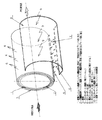
上記欠点を解消するため本発明は、図1に示すように螺旋状、または、同心円状に巻いたPET、PC等の各種樹脂材料からなる平面、あるいは、プリーツ状等に加工した光触媒担持フィルタ(2)に効果的に光エネルギーを照射するための拡散フィルム(1)、螺旋状に同様に巻いた光触媒を繊維状素材等に担持したフィルタ素材(2)、光触媒の機能を再生するための紫外線等の光エネルギーを供給する光源部等の光エネルギー供給端面部(4)これらを保持するための樹脂製あるいは鋼板製の筐体(3)とからなる光触媒フィルタである。
拡散フィルムは、フィルム端面から入力された光エネルギーがフィルムの表裏全面より光エネルギーを拡散させる機能を有しているもので、この面上から出力される光エネルギーを効果的に受光できるように拡散フィルム(1)と共に同心円状または、螺旋状に一体化された光触媒担持フィルタ(2)を配置することで光触媒担持フィルタ(2)に担持された酸化チタン等の光触媒に有効に光エネルギーを照射することを可能とする。
光エネルギーは光エネルギー供給端面部(4)の全体あるいは一部から光源等より入力することで光エネルギー入力端面(5)より光エネルギーが拡散フィルム内に入力され光エネルギー出力面(6)より均一に光エネルギーが照射されるため拡散フィルム(1)と同心円状、または、螺旋状に配置された光触媒担持フィルタ面に光エネルギーが均一に照射され光触媒担持フィルタ(2)に担持された光触媒機能を回復させることができる。In order to eliminate the above drawbacks, the present invention is a photocatalyst-carrying filter processed into a flat or pleated form made of various resin materials such as PET and PC wound spirally or concentrically as shown in FIG. 2) A diffusion film (1) for effectively irradiating light energy, a filter material (2) carrying a photocatalyst wound in a spiral manner on a fibrous material, etc., and an ultraviolet ray for regenerating the function of the photocatalyst It is a photocatalytic filter comprising a light energy supply end face part (4) such as a light source part for supplying light energy such as a resin or steel casing (3) for holding them.
The diffusion film has the function of diffusing light energy from the front and back of the film, so that the light energy input from the film end face is diffused so that the light energy output from this surface can be received effectively. The photocatalyst carrying filter (2) integrated concentrically or spirally with the film (1) is arranged to effectively irradiate the photocatalyst such as titanium oxide carried on the photocatalyst carrying filter (2) with light energy. Make it possible.
When light energy is input from the light source or the like from all or part of the light energy supply end face (4), the light energy is input from the light energy input end face (5) into the diffusion film and is more uniform than the light energy output face (6). The photocatalyst function that is supported on the photocatalyst-carrying filter (2) by uniformly radiating light energy onto the photocatalyst-carrying filter surface arranged concentrically with the diffusion film (1) or in a spiral shape Can be recovered.
以下本発明の実施形態を図面について説明する。
光触媒機能を最大限に利用するには、有害ガスとの接触効率をフィルタ素材表面で行うことが光エネルギーを最も効果的に光触媒を担持したフィルタ素材に照射することを可能にする。
したがい、図1にあるように螺旋状、または、円筒上に加工できる程度の柔軟性と強度を有する。
たとえば、ポリエチレン・ポリカーボネート樹脂等を基材とする拡散フィルム(1)を利用し光触媒を担持したプリーツ状に折り加工されたフィルタ素材(2)と共に螺旋状に連続して形成すれば良い。
この時に、拡散フィルム(1)とフィルタ素材(2)の接触面は、溶着あるいは接着により形状保持しても良い。
拡散フィルム(1)は、その端面から入力した光エネルギーをフィルムの両表面から放出する性能を有している。
この拡散フィルム(1)と一体に連続的に巻かれた光触媒フィルタ(2)は、拡散フィルムの両面から放出される光エネルギーにより光触媒機能を回復させることが可能となる。
螺旋状に形成された拡散フィルム(1)と光触媒が担持されたフィルタ素材(2)は、その断面方向より有害ガスを取り込むことで吸着処理するので、この断面方向の厚さである気流通過距離(7)を任意に調整することで吸着効率を高くすることもできる。
光触媒を担持されプリーツ状に折り加工されたフィルタ素材(1)は、任意の折り山高さにすることで表面積の増減が容易であり光触媒担持量も容易に調整可能である。
有害ガスの処理能力の一つである吸着効率については、プリーツ折り加工の山高さによりフィルタ素材の面積を増加することで吸着能力を向上させることもできる。
あるいは、断面方向の奥行き(7)を増加させることで有害ガスとの接触時間を容易に増加させることもできるので同様に吸着効率が向上する。
処理能力のもう一つは、処理風量であるがこれには有害ガスを通気する際の通気抵抗なるものを考慮しなければならないが、この様な場合でもプリーツ折り山高さを増加させて螺旋状に形成する巻数を増加させれば容易に処理風量を増加させることもできる。
これらの形状にすることで光触媒を担持したフィルタ素材(2)は、拡散フィルム(1)両表面から照射される光エネルギーをフィルタ素材両表面より受けることになり有害物質を吸着した光触媒の機能回復に十分な光エネルギーを与えることができる。
以上のことから以下のような実施形態となる。
拡散フィルム(1)とフィルタ素材(2)は、螺旋状、または、同心円状に形成する。
フィルタ素材(2)は、光触媒担持量を増加させることで有害ガス吸着量が増加するのでプリーツ状等に折り加工することで面積を増加させ、拡散フィルム(1)と連続的に一体となるよう形成する。
プリーツ加工は、拡散フィルム(1)側でもフィルタ素材(2)側どちらでも良い。
プリーツ状に形成した拡散フィルム(1)あるいは、フィルタ素材(2)は、プリーツ折り山高さを任意に変更することが可能であり、必要な有害ガス通気抵抗とすることができる。
螺旋状に形成された拡散フィルム(1)とフィルタ素材(2)は、有害ガス流路方向の厚さ(7)を任意に変更することで必要な有害ガス吸着効率を得ることができる。
螺旋状に形成された拡散フィルム(1)の端面は、筐体(3)のたとえば外側に取出し、その端面と光触媒の機能回復に必要な光源部(4)とを接続する。
光源部は、ブラックライト等の紫外線ランプあるいはLEDを通常使用するが図2にあるような集光フィルム(8)を利用することで、自然光である太陽光にさらすこととしても良い。
光触媒の機能回復のための光源部は、螺旋状に形成された光触媒を担持したフィルタ素材の下流側であれば有害ガス吸着処理後のガスであるので下流側の接ガス部に設置しても良い。Embodiments of the present invention will be described below with reference to the drawings.
In order to make the best use of the photocatalytic function, the contact efficiency with harmful gas is performed on the surface of the filter material, so that the light energy can be irradiated to the filter material carrying the photocatalyst most effectively.
Therefore, as shown in FIG. 1, it has flexibility and strength enough to be processed into a spiral or cylinder.
For example, a diffusion film (1) based on polyethylene / polycarbonate resin or the like may be used and continuously formed in a spiral shape together with a filter material (2) folded into a pleat shape carrying a photocatalyst.
At this time, the contact surface between the diffusion film (1) and the filter material (2) may be held in shape by welding or adhesion.
The diffusion film (1) has a capability of emitting light energy input from its end face from both surfaces of the film.
The photocatalytic filter (2) continuously wound integrally with the diffusion film (1) can recover the photocatalytic function by light energy emitted from both sides of the diffusion film.
Since the spirally formed diffusion film (1) and the filter material (2) carrying the photocatalyst are adsorbed by taking in harmful gas from the cross-sectional direction, the airflow passage distance which is the thickness in the cross-sectional direction Adsorption efficiency can also be increased by arbitrarily adjusting (7).
The filter material (1) carrying the photocatalyst and folded into a pleat shape can easily increase or decrease the surface area and can easily adjust the amount of the photocatalyst carried by adjusting the fold height to an arbitrary level.
As for the adsorption efficiency, which is one of the toxic gas processing capabilities, the adsorption capability can be improved by increasing the area of the filter material according to the height of the pleated folds.
Alternatively, by increasing the depth (7) in the cross-sectional direction, it is possible to easily increase the contact time with the harmful gas, so that the adsorption efficiency is similarly improved.
Another processing capacity is the processing air volume, which must be considered as resistance to ventilation when venting harmful gases, but even in such a case, the pleat fold height is increased to form a spiral. If the number of turns formed is increased, the processing air volume can be easily increased.
With these shapes, the filter material (2) carrying the photocatalyst receives the light energy irradiated from both surfaces of the diffusion film (1) from both surfaces of the filter material, and the function of the photocatalyst that adsorbs harmful substances is restored. Can provide sufficient light energy.
From the above, the following embodiment is obtained.
The diffusion film (1) and the filter material (2) are formed in a spiral shape or a concentric shape.
The filter material (2) increases the amount of harmful gas adsorbed by increasing the amount of photocatalyst supported, so the area of the filter material (2) is increased by folding it into a pleated shape, etc., so that it is continuously integrated with the diffusion film (1). Form.
The pleating may be performed on either the diffusion film (1) side or the filter material (2) side.
The diffusion film (1) or the filter material (2) formed in a pleat shape can arbitrarily change the height of the pleat folds, and can provide a necessary harmful gas ventilation resistance.
The diffusion film (1) and the filter material (2) formed in a spiral shape can obtain the necessary harmful gas adsorption efficiency by arbitrarily changing the thickness (7) in the harmful gas flow path direction.
The end surface of the diffusion film (1) formed in a spiral shape is taken out, for example, to the outside of the housing (3), and the end surface is connected to the light source part (4) necessary for the functional recovery of the photocatalyst.
The light source unit normally uses an ultraviolet lamp such as a black light or an LED, but may be exposed to sunlight, which is natural light, by using a condensing film (8) as shown in FIG.
The light source part for recovering the function of the photocatalyst is a gas after the harmful gas adsorption treatment as long as it is downstream of the filter material carrying the photocatalyst formed in a spiral shape. good.
拡散フィルムによりプリーツ加工等されたフィルタ素材の深部(奥行き方向ならびに両表面)にも光エネルギーを照射可能となり再生効率が高いため光触媒をフィルタ素材表面へ担持する最も容易な工法で有害ガス吸着に必要な面積を十分にとることができる。
有害ガスの吸着処理能力である吸着効率並びに処理風量において光触媒機能回復可能な条件で必要な吸着効率・処理風量を容易にかつ安価に製作できる。
光触媒機能回復のために必要な光源を気流内部である接ガス部におく必要がなく装置構造が簡単になる。
自然光である太陽光を利用することで装置がさらに簡素化できる。Necessary for adsorbing harmful gases with the simplest method of supporting a photocatalyst on the filter material surface because light energy can be irradiated to the deep part (depth direction and both surfaces) of the filter material that has been pleated by a diffusion film and the regeneration efficiency is high. A sufficient area can be taken.
It is possible to easily and inexpensively manufacture the necessary adsorption efficiency and treatment air volume under the conditions that the photocatalytic function can be recovered in the adsorption efficiency and the treatment air quantity that are adsorption treatment ability of harmful gas.
It is not necessary to place a light source required for recovery of the photocatalytic function in the gas contact part inside the air stream, and the structure of the apparatus is simplified.
The apparatus can be further simplified by using sunlight, which is natural light.
1 拡散フィルム
2 光触媒担持フィルタ
3 筐体
4 光エネルギー供給部(光源部接続部:拡散フィルム)
5 光エネルギー入力端面(拡散フィルム)
6 光エネルギー出力面(拡散フィルム)
7 気流通過距離(接ガス距離)
8 集光フィルム
9 光エネルギー入力面(集光フィルム)
10 光エネルギー出力端面(集光フィルム)DESCRIPTION OF SYMBOLS 1 Diffusion film 2 Photocatalyst carrying filter 3 Case 4 Light energy supply part (light source part connection part: Diffusion film)
5 Light energy input end face (diffusion film)
6 Light energy output surface (diffusion film)
7 Airflow passage distance (gas contact distance)
8 Condensing
10 Light energy output end face (light collecting film)
Claims (1)
Priority Applications (1)
| Application Number | Priority Date | Filing Date | Title |
|---|---|---|---|
| JP2007306503A JP2009106921A (en) | 2007-10-30 | 2007-10-30 | Photocatalytic filter |
Applications Claiming Priority (1)
| Application Number | Priority Date | Filing Date | Title |
|---|---|---|---|
| JP2007306503A JP2009106921A (en) | 2007-10-30 | 2007-10-30 | Photocatalytic filter |
Publications (1)
| Publication Number | Publication Date |
|---|---|
| JP2009106921A true JP2009106921A (en) | 2009-05-21 |
Family
ID=40776045
Family Applications (1)
| Application Number | Title | Priority Date | Filing Date |
|---|---|---|---|
| JP2007306503A Pending JP2009106921A (en) | 2007-10-30 | 2007-10-30 | Photocatalytic filter |
Country Status (1)
| Country | Link |
|---|---|
| JP (1) | JP2009106921A (en) |
Cited By (3)
| Publication number | Priority date | Publication date | Assignee | Title |
|---|---|---|---|---|
| CN104984661A (en) * | 2015-06-26 | 2015-10-21 | 中冶南方工程技术有限公司 | Photocatalyst reactor, photocatalyst reaction tower and flue gas purification system |
| JP2016530918A (en) * | 2012-07-27 | 2016-10-06 | ディ. クロスニィー マーク | Air sterilization and disinfection equipment |
| CN107098542A (en) * | 2017-06-22 | 2017-08-29 | 广西国宏智鸿环境科技发展有限公司 | A kind of solar energy domestic sewage processing system |
-
2007
- 2007-10-30 JP JP2007306503A patent/JP2009106921A/en active Pending
Cited By (4)
| Publication number | Priority date | Publication date | Assignee | Title |
|---|---|---|---|---|
| JP2016530918A (en) * | 2012-07-27 | 2016-10-06 | ディ. クロスニィー マーク | Air sterilization and disinfection equipment |
| CN104984661A (en) * | 2015-06-26 | 2015-10-21 | 中冶南方工程技术有限公司 | Photocatalyst reactor, photocatalyst reaction tower and flue gas purification system |
| CN104984661B (en) * | 2015-06-26 | 2017-04-05 | 中冶南方工程技术有限公司 | Photocatalyst reaction device, photocatalyst reaction tower and flue gas purification system |
| CN107098542A (en) * | 2017-06-22 | 2017-08-29 | 广西国宏智鸿环境科技发展有限公司 | A kind of solar energy domestic sewage processing system |
Similar Documents
| Publication | Publication Date | Title |
|---|---|---|
| JP6730272B2 (en) | Small air purifier using UV LED and photocatalytic filter | |
| CN104955490B (en) | Air Purifier Using UV Light Emitting Diodes | |
| EP1601916B1 (en) | Unit for filtering and treatment of organic compounds, method for production thereof and air-conditioning unit provided with such a unit | |
| CN103611418B (en) | Joint treatment device and method for organic waste gas | |
| JP2002238981A (en) | Air purification equipment | |
| CN113613756A (en) | Filter part and air purifier | |
| CN201012627Y (en) | A car air purifier | |
| KR100807152B1 (en) | Filter of polluted air | |
| JPH1147635A (en) | Air purifying device | |
| JP2004305436A (en) | Photocatalytic deodorization system | |
| JP2002306587A (en) | Air purification device and air purification filter | |
| CN114183874A (en) | Purification device and air conditioner | |
| KR20130024642A (en) | Deodorizing apparatus | |
| JP4834911B2 (en) | Air purification device | |
| KR200340227Y1 (en) | Air strilization apparatus using photo catalyst | |
| JPH0360720A (en) | Air purifier | |
| KR20220049123A (en) | Air purifier | |
| US8440144B2 (en) | Metallic photocatalytic oxidation reflector coated with titanium dioxide | |
| CN108626831A (en) | Air-purifying module and air cleaning unit containing it | |
| CN204543809U (en) | Special-purpose air clarifier | |
| CN211988008U (en) | A new type of ion catalytic equipment for treating odor and waste gas | |
| KR20050031331A (en) | Cylindrical uv+tio2 air cleaner | |
| TWM539352U (en) | Photoioncatalytic reactor | |
| TWI634916B (en) | Photoioncatalytic reactor | |
| KR20040019426A (en) | air cleaning apparatus using the light catalyzer filter |