JP2009106962A - Press machine - Google Patents
Press machine Download PDFInfo
- Publication number
- JP2009106962A JP2009106962A JP2007280913A JP2007280913A JP2009106962A JP 2009106962 A JP2009106962 A JP 2009106962A JP 2007280913 A JP2007280913 A JP 2007280913A JP 2007280913 A JP2007280913 A JP 2007280913A JP 2009106962 A JP2009106962 A JP 2009106962A
- Authority
- JP
- Japan
- Prior art keywords
- slide
- setup position
- setup
- molding operation
- position stop
- Prior art date
- Legal status (The legal status is an assumption and is not a legal conclusion. Google has not performed a legal analysis and makes no representation as to the accuracy of the status listed.)
- Pending
Links
- 230000033001 locomotion Effects 0.000 claims abstract description 19
- 238000001514 detection method Methods 0.000 claims abstract description 3
- 238000000465 moulding Methods 0.000 claims description 59
- 230000007246 mechanism Effects 0.000 claims description 20
- 101100477823 Mus musculus Smtn gene Proteins 0.000 description 11
- 230000007274 generation of a signal involved in cell-cell signaling Effects 0.000 description 7
- 101000710013 Homo sapiens Reversion-inducing cysteine-rich protein with Kazal motifs Proteins 0.000 description 6
- 210000004247 hand Anatomy 0.000 description 6
- 101000661807 Homo sapiens Suppressor of tumorigenicity 14 protein Proteins 0.000 description 4
- 230000000694 effects Effects 0.000 description 4
- 238000004519 manufacturing process Methods 0.000 description 4
- 238000000034 method Methods 0.000 description 4
- 101000661816 Homo sapiens Suppression of tumorigenicity 18 protein Proteins 0.000 description 3
- 101000585359 Homo sapiens Suppressor of tumorigenicity 20 protein Proteins 0.000 description 3
- 102100029860 Suppressor of tumorigenicity 20 protein Human genes 0.000 description 3
- 238000012790 confirmation Methods 0.000 description 3
- 230000006872 improvement Effects 0.000 description 3
- 230000008569 process Effects 0.000 description 3
- 230000001133 acceleration Effects 0.000 description 2
- 230000009471 action Effects 0.000 description 2
- 230000008859 change Effects 0.000 description 2
- 108090000237 interleukin-24 Proteins 0.000 description 2
- 230000003287 optical effect Effects 0.000 description 2
- 230000002093 peripheral effect Effects 0.000 description 2
- 230000009467 reduction Effects 0.000 description 2
- 230000000630 rising effect Effects 0.000 description 2
- 101000760620 Homo sapiens Cell adhesion molecule 1 Proteins 0.000 description 1
- 101000911772 Homo sapiens Hsc70-interacting protein Proteins 0.000 description 1
- 101001139126 Homo sapiens Krueppel-like factor 6 Proteins 0.000 description 1
- 125000002066 L-histidyl group Chemical group [H]N1C([H])=NC(C([H])([H])[C@](C(=O)[*])([H])N([H])[H])=C1[H] 0.000 description 1
- 239000012141 concentrate Substances 0.000 description 1
- 230000007423 decrease Effects 0.000 description 1
- 230000003247 decreasing effect Effects 0.000 description 1
- 238000010586 diagram Methods 0.000 description 1
- 230000006870 function Effects 0.000 description 1
- 210000000707 wrist Anatomy 0.000 description 1
Images





Landscapes
- Control Of Presses (AREA)
Abstract
Description
スライド駆動制御装置を備え、成形動作情報に基づきモータを回転駆動制御しかつスライド駆動機構を介してモータの回転運動をスライドの昇降運動に変換しつつ設定領域内でプレス成形可能に形成されたプレス機械に関する。 A press that is equipped with a slide drive control device and that controls the rotation of the motor based on molding operation information, and that is capable of press molding within the set area while converting the rotary motion of the motor to the slide up / down motion via the slide drive mechanism Related to machinery.
サーボモータを用いたプレス機械は、各種スライドモーションを容易に設定(選択)変更可能である(例えば、特許文献1)。スライドを一時停止、低速下降さらには昇降反転等もできるから、プレス成形態様に対する適応性を拡大できかつ高品質製品を生産できる。 A press machine using a servo motor can easily set (select) and change various slide motions (for example, Patent Document 1). Since the slide can be temporarily stopped, lowered at a low speed, and reversed up and down, the adaptability to the press molding mode can be expanded and a high-quality product can be produced.
かかるプレス機械では、スライド駆動制御装置(モータ回転制御部)が、予め設定された成形動作情報(成形動作指令信号)にしたがってモータを回転制御する。スライド駆動機構部は、モータ回転により発生されるモータ回転動力を入力として、スライドを駆動する。スライド駆動機構部としては、クランク機構、リンク機構あるいはねじ機構が知られているが、いずれのスライド駆動機構の場合でも、成形動作情報は、工程(時間、角度等)ごとのスライド位置として規定(作成)される。 In such a press machine, the slide drive control device (motor rotation control unit) controls the rotation of the motor in accordance with preset molding operation information (molding operation command signal). The slide drive mechanism unit drives the slide by using the motor rotation power generated by the motor rotation as an input. As the slide drive mechanism, a crank mechanism, a link mechanism or a screw mechanism is known, but in any slide drive mechanism, the molding operation information is defined as a slide position for each process (time, angle, etc.) Created).
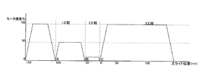
図8、図9は、スライド駆動機構部がクランク機構とされた場合の、プレス成形(生産)用のスライドモーションとモータ速度の一例を示す。図8の1工程(時間t1〜t2)は、最下位置(下死点)をゼロ(0mm)としたとき、スライドはA点高さ(100)からB点(50)まで下降される。2工程(時間t2〜t3)では、B点(50)からC点(0)まで下降される。3工程はスライドを最上位置(上死点…図示省略)まで上昇させる。スライド速度は、加減速域を除き一定である。 8 and 9 show an example of slide motion and motor speed for press molding (production) when the slide drive mechanism is a crank mechanism. In one step (time t1 to t2) in FIG. 8, when the lowest position (bottom dead center) is set to zero (0 mm), the slide is lowered from the point A height (100) to the point B (50). In 2 steps (time t2-t3), it falls from B point (50) to C point (0). In step 3, the slide is raised to the uppermost position (top dead center: not shown). The slide speed is constant except for the acceleration / deceleration range.
ところで、最初のプレス生産前には、実際プレス運転と同様な試運転によりスライド駆動を行ないつつ、いわゆる段取作業(例えば、A点で金型や周辺機器との干渉が生じるか否かをチェックする。B点で成形状態に関する予測確認をする。)が行なわれている。 By the way, before the first press production, a slide drive is performed by a trial operation similar to an actual press operation, and a so-called setup operation (for example, whether or not interference with a mold or peripheral equipment occurs at point A is checked. Prediction confirmation regarding the molding state is performed at point B).
A点にスライドを一旦停止させるには、いわゆる寸動モードでスライドを下降させている。なお、実際プレス運転が寸動モード、安全一行程モードあるいは連続モードのいずれで行なわれる場合でも、段取作業に限っては寸動モードと同じ運転態様でスライドを下降させている。 In order to temporarily stop the slide at the point A, the slide is lowered in a so-called inching mode. Whether the actual press operation is performed in the inching mode, the safe one-stroke mode, or the continuous mode, the slide is lowered in the same operation mode as in the inching mode only in the setup operation.
つまり、A点の手前に来ると、運転ボタンを極短時間だけ押下してスライド下降量を小さくし、この繰返しによりスライドを次第にA点(100mm)に近づけつつ、その位置で停止させている。B点に停止させる場合も同様である。したがって、慎重な作業が求められ、長時間を要する。作業者の経験と慣れによるところが大きいので、作業時間にバラツキが多い。 That is, when it comes before point A, the operation button is pressed for an extremely short time to reduce the slide lowering amount. By repeating this operation, the slide is gradually brought closer to point A (100 mm) and stopped at that position. The same applies when stopping at point B. Therefore, careful work is required and it takes a long time. There is a lot of variation in working hours because it depends largely on the experience and familiarity of the workers.
サーボプレスの優位性を十二分に発揮させかつ一段の普及拡大を図るには、生産に先立つ段取作業のために必要とするスライド位置決め停止の容易化と時間短縮化が重要である。 In order to make full use of the advantages of servo presses and to further spread and expand, it is important to make it easy to stop the slide positioning and shorten the time required for the setup work prior to production.
ここに、実際プレス運転用の成形動作情報にスライドをA点、B点で自動的に停止させるための情報を予め組込んでおく。そして、段取作業用の一定時間が経過すると、成形動作情報に基づく実際プレス運転に自動復帰させるという考え方がある。
しかし、かかる考え方は、段取作業位置(例えば、A点)におけるスライドの停止時間を設定しておくことになる。これを経験と慣れに任せると、設定時間が短く設定された場合は段取作業が未完成になる事態を招き易く、長く設定された場合は無駄時間を費やすことになるで生産性を低下させる虞が強い。 However, this idea is to set a slide stop time at the setup work position (for example, point A). If this is left to the experience and familiarity, if the set time is set short, the setup work tends to be unfinished, and if it is set long, it wastes time and decreases productivity. There is a strong fear.
また、自動的に発せられる電気信号(例えば、搬送終了信号)により、自動復帰させる方法がとられる。つまり、段取作業中にスライドが突然に動き出してしまう事態が発生する。危険極まりない。 Further, a method of automatically returning by an electric signal (for example, a conveyance end signal) that is automatically issued is used. That is, a situation occurs in which the slide suddenly starts during the setup work. There is no danger.
さらに、起動(立ち上げ)の度に、スライドが必ず停止することになる。その停止時間が無駄であるケースもある。生産性向上に反すると指摘されている。 Furthermore, the slide is always stopped every time it is activated (started up). In some cases, the stop time is wasted. It is pointed out that it goes against productivity improvement.
特に、作業要員の人材不足等との関係も相俟って、作業性と生産性との観点から段取作業についての運用上の実務的観点から、見直しが求められている。 In particular, a review is required from the practical point of view of the setup work from the viewpoint of workability and productivity, in combination with the relationship between the shortage of work personnel and the like.
本発明の目的は、作業者の安全を確実に担保した上で、段取作業を迅速かつ容易に行えるプレス機械を提供することにある。 The objective of this invention is providing the press machine which can perform a setup operation | work quickly and easily, ensuring a worker's safety reliably.
請求項1の発明に係るプレス機械は、成形動作情報に基づきモータを回転駆動制御するスライド駆動制御装置を備え、スライド駆動機構を介してモータの回転運動をスライドの昇降運動に変換しつつ設定領域内でプレス成形可能に形成されたプレス機械において、作業者の成形動作指令操作が継続している限りにおいて前記回転駆動制御を継続実行可能に形成し、段取位置停止実行宣言が成されかつスライド位置と予め設定された段取位置とが等しいと判別されたことを条件に成形動作指令操作が継続されているにも拘らず前記モータ回転駆動制御を強制的に中断させてスライドを設定段取位置に停止させる段取位置停止制御に切換可能に形成し、段取位置停止制御中に成形動作指令操作が一旦解除されかつその後に再び成されたことを条件に段取位置停止制御を解除しかつ中断されていた前記回転駆動制御に戻し切換可能に形成されている。 The press machine according to the first aspect of the present invention includes a slide drive control device that rotationally controls the motor based on the molding operation information, and converts the rotational motion of the motor into a lift motion of the slide via the slide drive mechanism. In the press machine formed so as to be capable of being press-formed, the rotation drive control can be continuously executed as long as the operator continues the forming operation command operation, the setup position stop execution declaration is made, and the slide The slide is set by forcibly interrupting the motor rotation drive control even though the molding operation command operation is continued on the condition that the position is determined to be equal to the preset setup position. It is possible to switch to the setup position stop control to stop at the position, and the molding operation command operation is once canceled during the setup position stop control, and then it is performed again. Back to release to the rotation drive control and had been interrupted setup position stop control is switchable formed.
また、請求項2に係るプレス機械は、成形動作情報に基づきモータを回転駆動制御するスライド駆動制御装置を備え、スライド駆動機構を介してモータの回転運動をスライドの昇降運動に変換しつつ設定領域内でプレス成形可能に形成されたプレス機械において、作業者の成形動作指令操作が成されている場合に成形動作指令信号を発生する成形動作指令信号発生手段を設けかつ前記スライド駆動制御装置を成形動作指令信号が継続して発生されている限りにおいて前記回転駆動制御を継続実行可能に形成し、段取位置を設定する段取位置設定手段と、設定された段取位置を記憶する記憶手段と、段取位置停止実行宣言を成すための段取位置停止実行宣言手段と、検出されたスライド位置と記憶手段に記憶された設定段取位置とが等しいか否かを判別可能な判別手段と、段取位置停止実行宣言が成されかつ判別手段により検出スライド位置と記憶設定段取位置とが等しいと判別されたことを条件に成形動作指令信号が継続して発生されているにも拘らず前記スライド駆動制御装置の前記モータ回転駆動制御を強制的に中断させてスライドを記憶設定段取位置に停止させるための段取位置停止制御を行なう段取位置停止制御手段と、段取位置停止制御中に成形動作指令信号が一旦消滅しかつその後に再び発生されたことを条件に段取位置停止解除信号を発生する段取位置停止解除信号発生手段と、段取位置停止解除信号が発生された場合に段取位置停止制御を解除しかつ中断されていた前記回転駆動制御に戻し切換する戻し切換制御手段と、を設けてなる。 The press machine according to claim 2 is provided with a slide drive control device that rotationally controls the motor based on the molding operation information, and converts the rotational motion of the motor into a lifting motion of the slide via the slide drive mechanism. In a press machine formed so as to be capable of being press-molded, a molding operation command signal generating means for generating a molding operation command signal is provided when an operator performs a molding operation command operation, and the slide drive control device is molded. As long as the operation command signal is continuously generated, the rotation drive control is formed so as to be continuously executable, a setup position setting means for setting the setup position, and a storage means for storing the set setup position Whether the setup position stop execution declaration means for making the setup position stop execution declaration is equal to the detected slide position and the set setup position stored in the storage means The molding operation command signal is continuously generated on the condition that the determination means capable of discriminating and the setup position stop execution declaration have been made and the discrimination means has determined that the detected slide position is equal to the stored set setup position. A setup position stop control means for performing setup position stop control for forcibly interrupting the motor rotation drive control of the slide drive control apparatus and stopping the slide at the storage set setup position despite being performed. And a setup position stop release signal generating means for generating a setup position stop release signal on condition that the molding operation command signal once disappears during setup position stop control and is then generated again, and a setup position. Return switching control means for canceling the setup position stop control and switching back to the interrupted rotation drive control when the stop cancellation signal is generated is provided.
また、請求項3の発明は、前記成形動作指令信号発生手段が、2つの押しボタンを両手で同時に押下操作されていることを条件に前記成形動作指令信号を発生可能に形成されている。さらに、請求項4の発明は、前記記憶手段が、複数段階の設定段取位置を記憶可能に形成されている。 According to a third aspect of the present invention, the molding operation command signal generating means is configured to be able to generate the molding operation command signal on condition that two push buttons are simultaneously pressed with both hands. Furthermore, in the invention of claim 4, the storage means is formed so as to be capable of storing a plurality of stages of set-up positions.
請求項1の発明によれば、作業者の安全を確実に担保した上で、段取作業を迅速かつ容易に行なうことができる。段取作業の時間短縮を促進できるので生産性を大幅に向上できる。 According to the first aspect of the invention, the setup work can be performed quickly and easily while ensuring the safety of the worker. Productivity can be greatly improved because the time required for setup work can be reduced.
請求項2の発明よれば、請求項1の発明の場合と同様な効果を奏することができることに加え、作業者の意思確認が反映されるので、適応性が広くかつ取扱いが容易である。 According to the invention of claim 2, in addition to being able to achieve the same effects as those of the invention of claim 1, since the operator's intention confirmation is reflected, the adaptability is wide and the handling is easy.
また、請求項3の発明によれば、請求項2の発明の場合と同様な効果を奏することができることに加え、作業者の上半身の安全確保が完璧となる。さらに、請求項4の発明によれば、請求項2および3の発明の場合と同様な効果を奏することができることに加え、さらに運用上の適応性が広い。 Further, according to the invention of claim 3, in addition to achieving the same effect as that of the invention of claim 2, ensuring the safety of the upper body of the worker is perfect. Furthermore, according to the invention of claim 4, in addition to being able to achieve the same effects as those of the inventions of claims 2 and 3, the operational flexibility is wide.
以下、本発明を実施するための最良の形態について、図面を参照して詳細に説明する。 Hereinafter, the best mode for carrying out the present invention will be described in detail with reference to the drawings.
(第1の実施の形態)
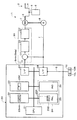
本プレス機械1は、図1〜図6に示す如く、スライド駆動制御装置30を成形動作指令信号Sが継続して発生されている限りにおいて回転駆動制御を継続実行可能に形成し、成形動作指令信号発生手段10(10L,10R)と段取位置設定手段25Pと記憶手段23Pと段取位置停止実行宣言手段25Dと判別手段(21,22,23)と段取位置停止制御手段(21,22,23)と段取位置停止解除信号発生手段(10)と戻し切換制御手段(21,22,23)とを設け、段取位置停止実行宣言が成されかつ検出されたスライド位置と予め設定された段取位置とが等しいと判別されたことを条件に成形動作指令操作が継続されているにも拘らずモータ回転駆動制御を強制的に中断させて段取位置停止制御に切換可能で、成形動作指令操作が一旦解除されかつその後に再び成されたことを条件に、段取位置停止制御を解除しかつ中断されていた回転駆動制御に戻し切換可能に形成されている。
(First embodiment)
As shown in FIGS. 1 to 6, the press machine 1 forms the slide
確認的に、プレス機械1は、成形動作情報に基づきモータ7を回転駆動制御するスライド駆動制御装置30を備え、スライド駆動機構(2)を介してモータの回転運動をスライド6の昇降運動に変換しつつ設定領域内でプレス成形可能に形成されている。
To be sure, the press machine 1 includes a slide
図1において、スライド駆動機構は、クランク軸3(クランク部4)を含むクランク機構2から構成されている。このクランク軸3は、軸受に回転自在に支持されかつ直接連結されたAC(交流)サーボモータ7の回転制御により可逆回転(正回転,逆回転)駆動制御可能である。サーボモータ7はDC(直流)サーボモータやリアクタンスモータとしてもよい。 In FIG. 1, the slide drive mechanism is composed of a crank mechanism 2 including a crankshaft 3 (crank portion 4). The crankshaft 3 can be reversibly rotated (forward rotation, reverse rotation) by rotation control of an AC (alternating current) servomotor 7 that is rotatably supported by a bearing and directly connected thereto. The servo motor 7 may be a DC (direct current) servo motor or a reactance motor.
なお、クランク軸3とモータ7とは、ギヤ(減速機)を介して間接的に連結させてもよい。ギヤ(減速機)を介せば、一段と高い加圧力を得ることができる。また、スライド駆動機構は、リンク機構やボールねじ機構から形成しても実施することができる。 In addition, you may connect the crankshaft 3 and the motor 7 indirectly via a gear (reduction gear). A higher pressurizing force can be obtained through a gear (reduction gear). Further, the slide drive mechanism can be implemented even when formed from a link mechanism or a ball screw mechanism.
スライド6は、フレーム本体に上下方向に摺動自在に装着され、バランス装置に係合されている。クランク軸3を回転駆動すれば、コネクティングロッド5を介してスライド6を昇降駆動することができる。金型はスライド6側の上型とボルスタ(図示省略)側の下型とからなる。 The slide 6 is mounted on the frame body so as to be slidable in the vertical direction, and is engaged with the balance device. If the crankshaft 3 is rotationally driven, the slide 6 can be driven up and down via the connecting rod 5. The mold is composed of an upper mold on the slide 6 side and a lower mold on the bolster (not shown) side.
ACサーボモータ7に連結されたエンコーダ8は、原理的には多数の光学的スリットと光学式検出器とを有し、モータ7(クランク軸3)の回転角度(クランク角度)θを出力するが、この実施形態では、回転角度(パルス信号)をスライド6の上下方向位置(パルス信号)に変換して出力する信号変換器(図示省略)を含むものとされている。 The encoder 8 connected to the AC servomotor 7 has in principle a large number of optical slits and optical detectors, and outputs the rotation angle (crank angle) θ of the motor 7 (crankshaft 3). In this embodiment, a signal converter (not shown) that converts the rotation angle (pulse signal) into the vertical position (pulse signal) of the slide 6 and outputs it is included.
図1において、プレス制御盤20は、CPU21,不揮発性のメモリ(ROMやHDD等)22,電源断でもデータを記憶保持可能なメモリ(フラッシュRAM等)23,タッチパネル24(操作部25および表示部26)およびインターフェース27・28を含み、メモリ22に格納されたプレス運転プログラムによりスライド駆動制御装置(モータ回転制御部)30にスライド駆動制御指令信号Smtnを生成出力してサーボモータ7を回転制御し、スライド6を昇降運動させることができる。なお、図1ではワーク搬送装置等に関する事項は記載省略している。
In FIG. 1, a
スライド6の成形動作情報(モーション軌跡)は、図5に示すように経過時間t(あるいは角度θとしてもよい。)とスライド位置Pとを対応させたデータであり、操作部25を用いて設定できる。設定された成形動作情報は、不揮発性メモリ22内の成形動作情報エリア22mtnに後で選択利用可能に記憶される。プレス運転に先立ち選択された成形動作情報は、記憶保持可能なメモリ23に展開される。
The forming operation information (motion trajectory) of the slide 6 is data in which the elapsed time t (or may be an angle θ) and the slide position P are associated with each other as shown in FIG. it can. The set molding operation information is stored in the molding operation information area 22mtn in the
プレス運転に際して、操作部25を用いて希望の成形動作情報を選択すると、位置パルスの払出し方式構造のスライド駆動制御指令部(21,22,23)は、メモリ22mtnに格納されたプレス運転プログラム(駆動制御指令信号生成出力制御プログラム)に従いスライド駆動制御指令信号Smtnをスライド駆動制御装置30に出力する。
When the desired forming operation information is selected using the
例えば、モータ回転速度が120RPMで、エンコーダ8から1回転(360度)当りに出力されるパルス数が100万パルスで、払出しサイクルタイムが5mSである場合は、1サイクル(5mS)毎に出力されるパルス数は、10000パルス[=(1000000×120)/(60×0.005)]となる。 For example, if the motor rotation speed is 120 RPM, the number of pulses output from the encoder 8 per rotation (360 degrees) is 1 million pulses, and the payout cycle time is 5 mS, it is output every cycle (5 mS). The number of pulses is 10,000 pulses [= (1000000 × 120) / (60 × 0.005)].
なお、急激なトルク変化を防止する策として、図6に示す如く起動直後に加速区間(出力パルス数を漸次増加)を、停止直前に減速区間(出力パルス数を漸次減少)を設けている。 As a measure for preventing a sudden torque change, an acceleration section (the number of output pulses is gradually increased) is provided immediately after startup, and a deceleration section (the number of output pulses is gradually decreased) immediately before stop as shown in FIG.
このスライド駆動制御指令信号Smtnを受けたスライド駆動制御装置30では、位置比較器31が目標値であるスライド駆動制御指令信号Smtnとエンコーダ8で検出された実際のスライド位置信号(フィードバック信号f)とを比較して位置偏差信号を生成出力する。位置速度制御部(位置制御部)32は、入力された位置偏差信号を累積し、それに位置ループゲインを乗じ、速度信号を生成出力する。速度比較器(図示省略)は速度信号と速度検出器(エンコーダ8)からの速度信号(この場合は信号fの速度成分)とを比較して速度偏差信号を生成出力する。
In the slide
速度制御部は、入力された速度偏差信号に速度ループゲインを乗じ電流指令信号を電流制御部(アンプ33)に生成出力する。この電流指令信号は、実質的にはトルク信号である。 The speed control unit multiplies the input speed deviation signal by a speed loop gain and generates and outputs a current command signal to the current control unit (amplifier 33). This current command signal is substantially a torque signal.
アンプ33は、各相目標電流信号を生成しかつ電流偏差信号を生成出力する。引続き、PWM制御、パルス幅変調により各相の電流偏差信号からPWM信号が生成される。最終的には、各PWM信号でスイッチング(ON/OFF)制御され、各相モータ駆動電流U,V,Wを出力することができる。かくして、サーボモータ7を回転駆動制御することができる。
The
ここに、成形動作指令信号発生手段10は、作業者の成形動作指令操作が成されている場合に、成形動作指令信号Sを発生する手段である。この手段としては、両手で押える1つの押しボタン型,ナイフスイッチ型やフートスイッチ型など種々あるが、この実施の形態では作業者の作業性と上半身(主に、手首)の保護との観点から、図1に示す2つの押しボタン10L,10Rから形成してある。
Here, the molding operation command signal generating means 10 is a means for generating the molding operation command signal S when the molding operation command operation of the operator is performed. As this means, there are various types such as one push button type that can be pressed with both hands, knife switch type and foot switch type. In this embodiment, from the viewpoint of workability of the operator and protection of the upper body (mainly wrist). The two
すなわち、両手で左右の押しボタン10L,10Rを同時に押し続けている間は、成形動作指令信号Sを継続して発生することができる。スライド駆動制御装置30は、成形動作指令信号Sが継続して発生されている限りにおいて、スライド駆動制御指令信号Smtnに従う回転駆動制御を継続実行可能に形成されている。
That is, the molding operation command signal S can be continuously generated while the left and
次に、段取位置設定手段は、段取位置(スライド位置)を設定する手段であり、操作部25内の置数キー等25Pから形成され、段取位置(例えば、図5の“A点”,“B点”,“C点”の各スライド位置)を設定することができる。この設定段取位置は、図2に示す如く記憶手段(メモリ23P)に記憶保持される。この実施の形態では、速度もリンクさせて記憶する。
Next, the setup position setting means is a means for setting a setup position (sliding position), and is formed from a numeric key 25P or the like in the
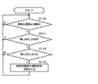
段取位置停止実行宣言手段は、宣言キー25Dから形成され、設定段取位置においてスライド6を強制的に停止させるための実行宣言を成す(図3のST15でYES)ために供される。この実行宣言は、プレスサイクルに1回で済むように形成することができるが、この実施の形態では、設定段取位置(Pin)ごとに宣言可能である(図3のST15で、YESまたはNO)。
The setup position stop execution declaration means is formed from a
判別手段(21,22,23)は、判別制御プログラムを格納させたメモリ22および展開用のメモリ23と当該プログラムを実行するCPU21とから形成され、検出されたスライド位置Piと記憶手段23Pに記憶された設定段取位置(例えば、“A点=100”、“B点=50”、“C点=0”mm)とが等しいか否かを判別(図3のST16〜ST18)する。
The discriminating means (21, 22, 23) is formed from the
段取位置停止制御手段(21,22,23…判別手段の場合と同様である。以下、同様。)は、段取位置停止実行宣言が成され(ST15でYES)かつ判別手段により検出スライド位置Piと記憶設定段取位置(Pin)とが等しいと判別されたことを条件(ST18でYES)に、段取位置停止制御を行なう。 The setup position stop control means (21, 22, 23... Is the same as in the case of the discrimination means. The same applies hereinafter) is made when the setup position stop execution declaration is made (YES in ST15) and the slide position detected by the discrimination means. The setup position stop control is performed on the condition that it is determined that Pi and the stored setting setup position (Pin) are equal (YES in ST18).
スライド6を記憶設定段取位置(Pin)に停止させるための段取位置停止制御は、成形動作指令信号発生手段(21,22,23)から成形動作指令信号Sが継続して発生されているにも拘らず、強制停止信号Sstpを出力してスライド駆動制御装置30のモータ回転駆動制御を強制的に中断させかつ停止させる。作業者の経験や慣れに優先する。中断停止は、位置速度制御部32に入力される位置偏差をゼロ(モータロック)とする状態である。
In the setup position stop control for stopping the slide 6 at the memory setting setup position (Pin), the molding operation command signal S is continuously generated from the molding operation command signal generating means (21, 22, 23). Nevertheless, the forced stop signal SStp is output to forcibly interrupt and stop the motor rotation drive control of the slide
段取位置停止解除信号発生手段(21,22,23)は、段取位置停止制御中(図4のST30でYES)に、成形動作指令信号Sが一旦消滅(ST31でYES)しかつその後に再び発生(ST32でYES)されたことを条件に段取位置停止解除信号(S)を発生する(ST33、図3のST20でYES)。一旦消滅から再びの発生までの許容時間(例えば、1秒以内)を管理するのが好ましい。 During the setup position stop control (YES in ST30 in FIG. 4), the setup position stop release signal generating means (21, 22, 23) once extinguishes (YES in ST31) and thereafter A setup position stop release signal (S) is generated on the condition that it is generated again (YES in ST32) (ST33, YES in ST20 of FIG. 3). It is preferable to manage an allowable time (for example, within 1 second) from once disappearing to reoccurring.
戻し切換制御手段(21,22,23)は、段取位置停止解除信号が発生された場合(ST20でYES)に、段取位置停止制御を解除しかつ中断されていたスライド駆動制御指令信号Smtnに基づく回転駆動制御に戻し切換する(ST21)。 The return switching control means (21, 22, 23) cancels the setup position stop control and interrupts the slide drive control command signal Smtn when the setup position stop release signal is generated (YES in ST20). Switch back to the rotational drive control based on (ST21).
なお、図3のST14に記載した“Pin”は、最終の設定段取位置を示す。設定段取位置が3つ場合(一番目のA点と二番目のB点と三番目のC点)は、Pinは三番目のC点(0)である。 Note that “Pin” described in ST14 of FIG. 3 indicates the final set-up position. When there are three set-up positions (first A point, second B point, and third C point), Pin is the third C point (0).
但し、ST22の場合は、任意の設定段取位置を示す。一番目の動作(ST10〜ST21)が終了した時に次は二番目と更新(Pin=Pin+1)させる。二番目から三番目への更新(歩進)も同じである。 However, in the case of ST22, an arbitrary set-up position is indicated. When the first operation (ST10 to ST21) is completed, the next operation is updated to the second operation (Pin = Pin + 1). The update from the second to the third (stepping) is the same.
この実施の形態では、現在のスライド位置Piが三番目の設定段取位置(C=0)以上でない場合(ST14でNO)は、段取位置停止制御動作(ST15〜ST22)には進まず、通常運転側(ST10)に戻す。 In this embodiment, when the current slide position Pi is not equal to or higher than the third set setup position (C = 0) (NO in ST14), the setup position stop control operation (ST15 to ST22) does not proceed. Return to the normal operation side (ST10).
なお、スライド上昇中のスライド位置Piは取扱い便宜上、マイナス(−)の位置とする。 It should be noted that the slide position Pi while the slide is rising is set to a minus (−) position for convenience of handling.
かかる構成の実施の形態では、成形動作指令信号発生手段10を形成する押しボタン10L,10Rを両手で同時に押下すると、成形動作指令信号Sが発生される(図3のST10でYES)。すると、スライド駆動制御指令部(21,22,23)が、スライド駆動制御指令信号Smtnをスライド駆動制御装置30に出力する。
In the embodiment having such a configuration, when the
かくして、モータ7の回転駆動制御が開始される(ST11でNO、ST12、ST13)。スライド6は図5に示すA点に向かって下降する。モータ速度は、図6に示す台形状である。回転駆動制御(ST11でYES)中の場合は、ST14へ進む。なお、途中に、押しボタン10L,10Rから片手または両手を離せば、回転駆動制御は停止される(ST10でNO、ST23)。
Thus, the rotational drive control of the motor 7 is started (NO in ST11, ST12, ST13). The slide 6 descends toward the point A shown in FIG. The motor speed is trapezoidal as shown in FIG. If the rotation drive control is being performed (YES in ST11), the process proceeds to ST14. In the middle, if one hand or both hands are released from the
検出スライド位置Piが一番目(A点)の設定段取位置Pin(=100mm)である場合(ST14でYES)でかつ段取位置停止実行宣言手段(25D)を用いた段取位置停止実行宣言が成されている場合(ST15でYES)は、スライド下降中に、判別手段がスライド6の検出(読取り)位置Piと一番目の設定段取位置Pinとが等しいと判別する(ST16、ST17、ST18でYES)。 When the detected slide position Pi is the first (A) set setup position Pin (= 100 mm) (YES in ST14), the setup position stop execution declaration using the setup position stop execution declaration means (25D) Is established (YES in ST15), the determination means determines that the detection (reading) position Pi of the slide 6 is equal to the first set-up position Pin during the slide lowering (ST16, ST17, YES at ST18).
すると、段取位置停止制御手段(21,22,23)は、段取位置停止制御により成形動作指令信号Sが継続して発生されているにも拘らずモータ回転駆動制御を強制的に中断させて、スライド6を記憶設定段取位置(A点…100mm)に停止(ST19)させる。経過時間はt1である。 Then, the setup position stop control means (21, 22, 23) forcibly interrupts the motor rotation drive control even though the molding operation command signal S is continuously generated by the setup position stop control. Then, the slide 6 is stopped (ST19) at the storage setting setup position (A point... 100 mm). The elapsed time is t1.
つまり、作業者が、スライド6の現在位置Piを目視確認し、経験と慣れにより押しボタン10L,10Rの押下、手放しを頻繁に繰り返しつつ、スライド6を一番目の段取位置(A点)に位置決めする手動運転をする必要がなくなる。手間と時間を大幅に削減できる。精神的肉体的にも解放されるので、本来的目的(段取作業)に集中できる。
In other words, the operator visually confirms the current position Pi of the slide 6 and frequently pushes and releases the
この強制的な中断・停止は、スライド駆動制御装置30内の偏差をゼロとするモータロック状態であるから、スライド6を確実に固定化できる。作業の安全を確約できる。
Since this forcible interruption / stop is a motor lock state in which the deviation in the slide
一方において、強制的な中断・停止時間の長短は、作業者の熟練度に応じて選択(指定)ができるように形成されている。すなわち、作業者が、自ら段取作業が完璧であると信じられるタイミングにおいて、自らの意思により作業終了宣言およびスライド下降許可宣言を行なう。 On the other hand, the length of the forced interruption / stop time is formed so that it can be selected (designated) according to the skill level of the operator. That is, the worker makes a work end declaration and a slide lowering permission declaration according to his / her own intention at the timing when the setup work is believed to be perfect.
スライド6が停止された図5に示すA点から停止解除点(A1点)までの停止継続時間は、作業者の総合能力によって決まる。つまり、熟練度の低い作業者(者)には慎重作業(比較的に長時間)を許し、高い者には生産性向上(短時間化)に対する貢献度を認める運用ができる。極めて、現実的で適応性の広いものであると理解できる。 The stop duration from the point A shown in FIG. 5 where the slide 6 is stopped to the stop release point (point A1) is determined by the operator's total ability. In other words, it is possible to allow a worker (person) with a low skill level to be cautious (relatively long time), and allow a high person to appreciate the contribution to productivity improvement (short time). It can be understood that it is extremely realistic and adaptable.
そして、押しボタン10L,10Rから手を離すと、成形動作指令信号Sが一旦消滅(図4のST31でYES)する。その後(例えば、1秒以内)に、再び押しボタン10L,10Rを押下すると、再び成形動作指令信号Sが発生(ST32でYES)される。これらの宣言行為が成されたことを条件に、段取位置停止解除信号(S)が発生される(ST33、図3のST20でYES)。作業者(人身)の安全も担保される。
Then, when the hand is released from the
かくして、段取位置停止制御が解除されかつスライド駆動制御指令信号Smtnに基づくスライド駆動(下降)に戻る(ST21)。点Bに向かって下降する。この際、Pin(一番目A点=100)を次のPin(二番目B点=50)に更新(Pin→Pin+1)しておく(ST22)。 Thus, the setup position stop control is canceled and the process returns to the slide drive (down) based on the slide drive control command signal Smtn (ST21). Go down to point B. At this time, Pin (first A point = 100) is updated to the next Pin (second B point = 50) (Pin → Pin + 1) (ST22).
以下、図5に示す二番目(B−B1点)、三番目(C−C1点)に関しても、一番目(A−A1点)の場合と同様に実行される。なお、停止実行宣言をしない(ST15でNO)ことにより、3つの設定段取位置の一部について、段取停止制御を実行しないことも、選択できる。生産プレス運転では、全部について停止実行宣言をしない。 Thereafter, the second (B-B1 point) and third (C-C1 point) shown in FIG. 5 are executed in the same manner as in the first (A-A1 point). Note that by not declaring stop execution (NO in ST15), it is possible to select not to execute the setup stop control for a part of the three set setup positions. In production press operation, stop execution declaration is not made for all.
しかして、この実施の形態によれば、成形動作指令信号発生手段10(10L,10R)と段取位置設定手段25Pと記憶手段23Pと段取位置停止実行宣言手段25Dと判別手段(21,22,23)と段取位置停止制御手段(21,22,23)と段取位置停止解除信号発生手段(10)と戻し切換制御手段(21,22,23)とを設け、段取位置停止実行宣言が成されかつ検出スライド位置と設定段取位置とが等しいと判別されたことを条件に成形動作指令操作が継続されているにも拘らず段取位置停止制御に切換可能で、成形動作指令操作が一旦解除されかつその後に再び成されたことを条件に回転駆動制御に戻し切換可能であるから、作業者の安全を確実に担保した上で、段取作業を迅速かつ容易に行なうことができる。段取作業の時間短縮を促進できるので生産性を大幅に向上できる。 Thus, according to this embodiment, the molding operation command signal generation means 10 (10L, 10R), the setup position setting means 25P, the storage means 23P, the setup position stop execution declaration means 25D, and the discrimination means (21, 22) 23), setup position stop control means (21, 22, 23), setup position stop release signal generation means (10), and return switching control means (21, 22, 23) are provided to execute setup position stop execution. Even if the molding operation command operation is continued on the condition that the declaration is made and it is determined that the detected slide position is equal to the set setup position, it is possible to switch to the setup position stop control. Since it is possible to switch back to rotational drive control on the condition that the operation is once canceled and then performed again, it is possible to perform setup work quickly and easily while ensuring the safety of the operator. it can. Productivity can be greatly improved because the time required for setup work can be reduced.
段取位置停止実行宣言をしておけば、成形動作指令操作が継続中でもスライド6を設定位置に正確に停止できので、金型や周辺機器との干渉を容易に確認できる。すなわち、作業者の経験と慣れによる技量にのみ左右されることがなく、安定した段取作業を行えかつ作業時間を短縮できる。スライドを加圧位置で停止させれば、停留時間の検証も可能である。 If the setup position stop execution declaration is made, the slide 6 can be accurately stopped at the set position even if the molding operation command operation is continued, so that interference with the mold and peripheral devices can be easily confirmed. That is, it is possible to perform stable setup work and shorten the work time without being affected only by the skill of the worker and experience. If the slide is stopped at the pressurizing position, the stopping time can be verified.
また、段取位置停止実行宣言手段25Dを用いた段取位置停止実行宣言と、成形動作指令信号発生手段10(10L,10R)を用いた段取位置停止解除宣言という形で、作業者の意思確認を反映することができるから、適応性が広くかつ取扱いが容易である。 In addition, the operator's intention in the form of a setup position stop execution declaration using the setup position stop execution declaration means 25D and a setup position stop release declaration using the molding operation command signal generation means 10 (10L, 10R). Since confirmation can be reflected, it is flexible and easy to handle.
また、成形動作指令信号発生手段が、2つの押しボタン10L、10Rを両手で同時に押下操作されていることを条件に成形動作指令信号を発生可能に形成されているので、作業者の上半身の安全確保が完璧となる。
Further, since the molding operation command signal generating means is formed so as to be able to generate the molding operation command signal on condition that the two
さらに、記憶手段23Pが、複数段階の設定段取位置を記憶可能であるから、運用上の適応性が広い。 Furthermore, since the storage means 23P can store a plurality of setting setup positions, the applicability in operation is wide.
(第2の実施の形態)
この実施の形態は、基本的な構成・機能が第1の実施形態の場合と同様とされているが、第1の実施形態の場合(エンコーダ8を用いたスライド6の検出位置と記憶手段23Pを用いた設定段取位置とを比較してスライド停止制御を実行可能に構築されている。)と異なり、電子カムを用いて設定記憶させた段取位置においてスライド停止制御を実行可能に形成されている。
(Second Embodiment)
In this embodiment, the basic configuration and function are the same as in the case of the first embodiment, but in the case of the first embodiment (the detected position of the slide 6 using the encoder 8 and the storage means 23P). It is constructed so that the slide stop control can be executed by comparing with the set setup position using the.), And the slide stop control can be executed at the setup position stored using the electronic cam. ing.
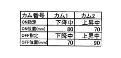
電子カムに設定した位置で発生される信号により、当該スライド位置で停止制御させることができる。図7の場合は、スライドの下降中にスライド位置が80mmとなったときにONとなりかつ70mmでOFFとなる信号を発する。つまり、スライド下降中は、80mmと70mmの2段階で停止制御可能である。 The stop control can be performed at the slide position by a signal generated at the position set in the electronic cam. In the case of FIG. 7, a signal that is turned on when the slide position becomes 80 mm while the slide is lowered and is turned off at 70 mm is generated. That is, the stop control can be performed in two stages of 80 mm and 70 mm while the slide is descending.
また、上昇中にスライド位置が70mmでONとなり90mmでOFFとなる信号を発する。つまり、スライド上昇中は、70mmと90mmの2段階で停止制御可能である。 Further, during the ascent, a signal is issued that turns ON when the slide position is 70 mm and OFF when it is 90 mm. That is, stop control is possible in two stages of 70 mm and 90 mm while the slide is rising.
なお、その他の構成・動作については、第1の実施の形態から容易に理解できるので、説明を省略する。 Since other configurations and operations can be easily understood from the first embodiment, description thereof will be omitted.
しかして、この実施の形態によれば、第1の実施の形態の場合と同様な効果を奏することができる。また、電子カムの取り扱いを熟知する者に対する本発明の利用性を高められる。 Thus, according to this embodiment, the same effects as those of the first embodiment can be obtained. In addition, the utility of the present invention for those who are familiar with the handling of electronic cams can be enhanced.
本発明は、段取作業の迅速・容易化並びに人身安全担保の確実化を企図する各種のプレス機械として利用できかつ生産性の向上に大きく貢献できる。 INDUSTRIAL APPLICABILITY The present invention can be used as various press machines intended to speed up and facilitate setup work and ensure personal safety, and can greatly contribute to improvement of productivity.
1 サーボプレス
2 クランク機構
6 スライド
7 サーボモータ
10 成形動作指令信号発生手段(段取位置停止解除信号発生手段)
10L,10R 押しボタン
20 プレス制御盤
21 CPU(判別手段、段取位置停止制御手段、戻し切換制御手段)
22 不揮発性メモリ(判別手段、段取位置停止制御手段、戻し切換制御手段)
23 記憶保持可能なメモリ(判別手段、段取位置停止制御手段、戻し切換制御手段)
23P 記憶手段
24 タッチパネル
25 操作部
25D 段取位置停止実行宣言手段
25P 段取位置設定手段
30 スライド駆動制御装置(モータ回転制御部)
32 位置速度制御部
DESCRIPTION OF SYMBOLS 1 Servo press 2 Crank mechanism 6 Slide 7
10L,
22 Non-volatile memory (discriminating means, setup position stop control means, return switching control means)
23 Memory that can be stored (discriminating means, setup position stop control means, return switching control means)
23P storage means 24
32 Position speed controller
Claims (4)
作業者の成形動作指令操作が継続している限りにおいて前記回転駆動制御を継続実行可能に形成し、
段取位置停止実行宣言が成されかつスライド位置と予め設定された段取位置とが等しいと判別されたことを条件に成形動作指令操作が継続されているにも拘らず前記モータ回転駆動制御を強制的に中断させてスライドを設定段取位置に停止させる段取位置停止制御に切換可能に形成し、
段取位置停止制御中に成形動作指令操作が一旦解除されかつその後に再び成されたことを条件に段取位置停止制御を解除しかつ中断されていた前記回転駆動制御に戻し切換可能に形成された、プレス機械。 A press machine that is provided with a slide drive control device that rotationally controls a motor based on molding operation information, and that is capable of press molding within a set region while converting the rotary motion of the motor into a lift motion of the slide via a slide drive mechanism In
As long as the molding operation command operation of the operator is continued, the rotation drive control is formed so as to be continuously executable,
The motor rotation drive control is performed in spite of the molding operation command operation being continued on the condition that the setup position stop execution declaration is made and it is determined that the slide position and the preset setup position are equal. It is possible to switch to setup position stop control that forcibly interrupts the slide and stops the slide at the set setup position.
The setup position stop control is canceled on the condition that the molding operation command operation is once canceled during the setup position stop control and then re-executed, and can be switched back to the interrupted rotation drive control. Press machine.
作業者の成形動作指令操作が成されている場合に成形動作指令信号を発生する成形動作指令信号発生手段を設けかつ前記スライド駆動制御装置を成形動作指令信号が継続して発生されている限りにおいて前記回転駆動制御を継続実行可能に形成し、
段取位置を設定する段取位置設定手段と、
設定された段取位置を記憶する記憶手段と、
段取位置停止実行宣言を成すための段取位置停止実行宣言手段と、
検出されたスライド位置と記憶手段に記憶された設定段取位置とが等しいか否かを判別可能な判別手段と、
段取位置停止実行宣言が成されかつ判別手段により検出スライド位置と記憶設定段取位置とが等しいと判別されたことを条件に成形動作指令信号が継続して発生されているにも拘らず前記スライド駆動制御装置の前記モータ回転駆動制御を強制的に中断させてスライドを記憶設定段取位置に停止させるための段取位置停止制御を行なう段取位置停止制御手段と、
段取位置停止制御中に成形動作指令信号が一旦消滅しかつその後に再び発生されたことを条件に段取位置停止解除信号を発生する段取位置停止解除信号発生手段と、
段取位置停止解除信号が発生された場合に段取位置停止制御を解除しかつ中断されていた前記回転駆動制御に戻し切換する戻し切換制御手段と、
を設けたプレス機械。 A press machine that is provided with a slide drive control device that rotationally controls a motor based on molding operation information, and that is capable of press molding within a set region while converting the rotary motion of the motor into a lift motion of the slide via a slide drive mechanism In
As long as a molding operation command signal generating means for generating a molding operation command signal is provided when an operator performs a molding operation command operation, and the molding operation command signal is continuously generated in the slide drive control device, Forming the rotational drive control to be continuously executable;
A setup position setting means for setting the setup position;
Storage means for storing the set setup position;
A setup position stop execution declaration means for making a setup position stop execution declaration;
Discriminating means capable of discriminating whether or not the detected slide position is equal to the set setup position stored in the storage means;
The molding operation command signal is continuously generated on the condition that the setup position stop execution declaration is made and the detection means determines that the detected slide position is equal to the stored setting setup position. Setup position stop control means for performing setup position stop control for forcibly interrupting the motor rotation drive control of the slide drive control device and stopping the slide at the storage setting setup position;
A setup position stop release signal generating means for generating a setup position stop release signal on the condition that the molding operation command signal once disappears during the setup position stop control and is then generated again;
A return switching control means for releasing the setup position stop control when the setup position stop release signal is generated and switching back to the interrupted rotation drive control;
Press machine.
Priority Applications (1)
| Application Number | Priority Date | Filing Date | Title |
|---|---|---|---|
| JP2007280913A JP2009106962A (en) | 2007-10-29 | 2007-10-29 | Press machine |
Applications Claiming Priority (1)
| Application Number | Priority Date | Filing Date | Title |
|---|---|---|---|
| JP2007280913A JP2009106962A (en) | 2007-10-29 | 2007-10-29 | Press machine |
Publications (1)
| Publication Number | Publication Date |
|---|---|
| JP2009106962A true JP2009106962A (en) | 2009-05-21 |
Family
ID=40776068
Family Applications (1)
| Application Number | Title | Priority Date | Filing Date |
|---|---|---|---|
| JP2007280913A Pending JP2009106962A (en) | 2007-10-29 | 2007-10-29 | Press machine |
Country Status (1)
| Country | Link |
|---|---|
| JP (1) | JP2009106962A (en) |
Cited By (3)
| Publication number | Priority date | Publication date | Assignee | Title |
|---|---|---|---|---|
| JP2011188579A (en) * | 2010-03-05 | 2011-09-22 | Hitachi Ltd | Permanent magnet synchronous machine |
| CN102208852A (en) * | 2010-03-30 | 2011-10-05 | 株式会社日立制作所 | Permanent magnet synchronous machine, and pressing or extrusion machine including permanent magnet synchronous machine |
| WO2019064693A1 (en) * | 2017-09-26 | 2019-04-04 | コマツ産機株式会社 | Press system and method for controlling press system |
Citations (2)
| Publication number | Priority date | Publication date | Assignee | Title |
|---|---|---|---|---|
| JPH115129A (en) * | 1997-06-12 | 1999-01-12 | Fuji Heavy Ind Ltd | Means and equipment to set up mold in press machine |
| JPH1158092A (en) * | 1997-08-07 | 1999-03-02 | Komatsu Ltd | Servo press position setting device and method |
-
2007
- 2007-10-29 JP JP2007280913A patent/JP2009106962A/en active Pending
Patent Citations (2)
| Publication number | Priority date | Publication date | Assignee | Title |
|---|---|---|---|---|
| JPH115129A (en) * | 1997-06-12 | 1999-01-12 | Fuji Heavy Ind Ltd | Means and equipment to set up mold in press machine |
| JPH1158092A (en) * | 1997-08-07 | 1999-03-02 | Komatsu Ltd | Servo press position setting device and method |
Cited By (7)
| Publication number | Priority date | Publication date | Assignee | Title |
|---|---|---|---|---|
| JP2011188579A (en) * | 2010-03-05 | 2011-09-22 | Hitachi Ltd | Permanent magnet synchronous machine |
| CN102208852A (en) * | 2010-03-30 | 2011-10-05 | 株式会社日立制作所 | Permanent magnet synchronous machine, and pressing or extrusion machine including permanent magnet synchronous machine |
| JP2011211819A (en) * | 2010-03-30 | 2011-10-20 | Hitachi Ltd | Permanent magnet synchronous machine and press machine or injection molding machine using the same |
| US8729762B2 (en) | 2010-03-30 | 2014-05-20 | Hitachi, Ltd. | Permanent magnet synchronous machine, and pressing or extrusion machine including permanent magnet synchronous machine |
| WO2019064693A1 (en) * | 2017-09-26 | 2019-04-04 | コマツ産機株式会社 | Press system and method for controlling press system |
| JP2019058921A (en) * | 2017-09-26 | 2019-04-18 | コマツ産機株式会社 | Press system and press system control method |
| CN110520286A (en) * | 2017-09-26 | 2019-11-29 | 小松产机株式会社 | Press system and control method for press system |
Similar Documents
| Publication | Publication Date | Title |
|---|---|---|
| JP5560356B1 (en) | Press machine and control method of press machine | |
| CN102958632B (en) | Tailstock device | |
| JP4969049B2 (en) | Bending machine | |
| JP2009142941A (en) | Control apparatus and control method | |
| JP5196566B2 (en) | Bending method and apparatus by robot | |
| KR100823407B1 (en) | Machine control, control method and foot stand | |
| TW200508445A (en) | Sewing machine | |
| JP2014097234A (en) | sewing machine | |
| JP4270497B2 (en) | Press machine | |
| JP4958726B2 (en) | Press machine | |
| JP2004025287A (en) | Pressing machine | |
| JP4084025B2 (en) | Sewing machine lifter | |
| JP2003260530A (en) | Pressing machine | |
| JP4843477B2 (en) | Brake control method for press and mechanical press | |
| CN100548522C (en) | Bending device | |
| JPH11192598A (en) | Press device | |
| JP2009160619A (en) | Servo press machine | |
| CN105134224B (en) | The control method of rectangular shield assembling machine | |
| JPH09201632A (en) | Material feeding device for press machine | |
| JPH11347634A (en) | Bending system | |
| JP2003211298A (en) | Press machine | |
| CN110520286B (en) | Stamping system and control method of stamping system | |
| JP2004174572A (en) | Bending device | |
| JP3789459B2 (en) | Sewing machine with automatic controller operation function | |
| JP3813620B2 (en) | Sewing machine with automatic controller operation function |
Legal Events
| Date | Code | Title | Description |
|---|---|---|---|
| RD04 | Notification of resignation of power of attorney |
Free format text: JAPANESE INTERMEDIATE CODE: A7424 Effective date: 20090213 |
|
| A621 | Written request for application examination |
Free format text: JAPANESE INTERMEDIATE CODE: A621 Effective date: 20100216 |
|
| A977 | Report on retrieval |
Free format text: JAPANESE INTERMEDIATE CODE: A971007 Effective date: 20120315 |
|
| A131 | Notification of reasons for refusal |
Free format text: JAPANESE INTERMEDIATE CODE: A131 Effective date: 20120321 |
|
| A02 | Decision of refusal |
Free format text: JAPANESE INTERMEDIATE CODE: A02 Effective date: 20120711 |