JP2009121237A - Kick starter motorcycle - Google Patents
Kick starter motorcycle Download PDFInfo
- Publication number
- JP2009121237A JP2009121237A JP2007292594A JP2007292594A JP2009121237A JP 2009121237 A JP2009121237 A JP 2009121237A JP 2007292594 A JP2007292594 A JP 2007292594A JP 2007292594 A JP2007292594 A JP 2007292594A JP 2009121237 A JP2009121237 A JP 2009121237A
- Authority
- JP
- Japan
- Prior art keywords
- kick
- pedal
- main stand
- kick pedal
- engine
- Prior art date
- Legal status (The legal status is an assumption and is not a legal conclusion. Google has not performed a legal analysis and makes no representation as to the accuracy of the status listed.)
- Pending
Links
Images


Landscapes
- Automatic Cycles, And Cycles In General (AREA)
Abstract
Description
本発明は、キック始動式自動二輪車の改良に関するものである。 The present invention relates to an improvement of a kick start type motorcycle.
無段変速機が搭載され、エンジンをキックペダルで始動する形式の自動二輪車が知られている(例えば、特許文献1、特許文献2参照。)。
このような自動二輪車では、キック始動時に後輪が接地していると、スロットルグリップの回動位置によってはエンジンが始動した際に後輪に大きな駆動力が伝わることがある。
2. Description of the Related Art A motorcycle equipped with a continuously variable transmission and starting an engine with a kick pedal is known (see, for example, Patent Document 1 and Patent Document 2).
In such a motorcycle, if the rear wheel is grounded at the time of kick start, depending on the rotation position of the throttle grip, a large driving force may be transmitted to the rear wheel when the engine is started.
このときの自動二輪車の運転者が意図しない発進を防止するために、特許文献1においては、後輪を接地させた状態、即ちメインスタンドを跳ね上げて格納した状態では、キックされたキックペダルがメインスタンドに係合し、キックペダルの回動を阻止している。
特許文献1の第2図、第4図を以下に説明する。
縦に延びるエンジン9の後部に自動無段変速機ケース10が一体的に連結されてスイング式エンジンユニット8が構成され、自動変速機ケース10の後端に後輪11が取付けられ、エンジン9の左側にキックアーム40、エンジン9の下部にメインスタンド25がそれぞれ回動自在に取付けられている。
2 and 4 of Patent Document 1 will be described below.
An automatic continuously
メインスタンド25の脚部26,26の一方に側方に延びる足掛け突起31が設けられ、キックアーム40にキックペダル41及び下方に突出する係合突起42が設けられている。
A
メインスタンド25が格納された状態では、キックアーム40のキックペダル41を踏み込んでエンジン25を始動させようとすると、キックペダル41の係合突起42がメインスタンド25の足掛け突起31に係合し、キックアーム40の回動が阻止され、エンジン9が始動できなくなる。
In the state where the
特許文献2の第1図〜第3図を以下に説明する。
自動二輪車のメインフレーム7の下部には、シリンダブロック22及びシリンダヘッド23がほぼ水平まで前傾姿勢にされたエンジンEと、無段変速機からなる動力伝達装置Tとで構成されたパワーユニットPが取付けられ、このパワーユニットPの後端部に回動自在にスイングアーム12が取付けられ、このスイングアーム12の後端部に後輪WRが取付けられている。
動力伝達装置Tの後部右側からキック軸95が突出し、このキック軸95にキックペダル96が取付けられている。
1 to 3 of Patent Document 2 will be described below.
Below the main frame 7 of the motorcycle, there is a power unit P composed of an engine E in which the cylinder block 22 and the cylinder head 23 are inclined forward to a substantially horizontal position and a power transmission device T composed of a continuously variable transmission. The
A kick shaft 95 projects from the rear right side of the power transmission device T, and a
特許文献1のようなスクータ型の自動二輪車では、スイング式エンジンユニット8の後端に後輪11が取付けられているため、エンジン9から後輪11までの距離が短くなり、メインスタンド25は、後輪11との干渉を防ぐためにスイング式パワーユニット8の前端寄りに設けられる。
In a scooter type motorcycle such as Patent Document 1, since the
この結果、メインスタンド25と、エンジン9の左側方に設けられたキックアーム40との前後方向の位置が近くなり、インスタンド25の足掛け突起31とキックアーム40とを係合させることは容易であるが、特許文献2のような自動二輪車では、後輪WRがパワーユニットPの後端部にスイングアーム12を介して取付けられているために、メインスタンドは車体の前後をバランス良く支持するためにより後輪WR側に配置されるので、メインスタンドとキックペダル96とが前後方向に大きく離れることになる。
As a result, the position in the front-rear direction of the
更に、メインスタンドとキックペダル96との間にサイドスタンドが配置されている場合には、メインスタンドとキックペダル96とが前後方向に加えて車幅方向にも大きく離れることになり、メインスタンドでキックペダル96の回動を阻止することが難しくなる。
Further, when a side stand is disposed between the main stand and the
本発明の目的は、無段変速機又は車体フレームにスイングアームを介して後輪が取付けられたキック始動式自動二輪車において、メインスタンドを格納した状態でのキックペダルによるエンジン始動を防止することにある。 An object of the present invention is to prevent engine start by a kick pedal in a state where a main stand is stored in a continuously variable transmission or a kick start type motorcycle in which a rear wheel is attached to a body frame via a swing arm. is there.
請求項1に係る発明は、車体フレームに、エンジン及びこのエンジンの後部に一体的に連結された無段変速機からなるパワーユニットが支持され、車体フレームにスイングアームを介して支持される後輪とメインスタンドとが取付けられ、パワーユニットの側部にキックペダルが取付けられ、平面視でこれらのメインスタンド及びキックペダルのそれぞれの間にサイドスタンドが配置され、メインスタンドに、車体フレームに回動自在に支持された軸支部とこの軸支部から延ばされた脚部とこの脚部から車体側方に延びる足掛け部とを備え、キックペダルに、パワーユニット側の回動軸に取付けられたアーム部とこのアーム部に取付けられたペダル部とを備えたキック始動式自動二輪車において、キックペダルに、アーム部に対してペダル部とは反対方向に延びる当接部が設けられ、メインスタンドを立てて車体を支持した状態から跳ね上げた状態にして、エンジンで駆動される後輪を接地させたときに、キックされたキックペダルの当接部がメインスタンドの一部と当たるようにしたことを特徴とする。 According to a first aspect of the present invention, there is provided a rear wheel supported on a vehicle body frame via a swing arm, wherein the vehicle body frame supports a power unit including an engine and a continuously variable transmission integrally connected to a rear portion of the engine. A main stand is attached, a kick pedal is attached to the side of the power unit, and a side stand is disposed between each of the main stand and the kick pedal in a plan view, and the main stand is rotatably supported by the body frame. And a leg portion extending from the shaft support portion and a footrest portion extending from the leg portion to the side of the vehicle body. The arm portion attached to the rotating shaft on the power unit side and the arm In a kick starter type motorcycle equipped with a pedal portion attached to the arm portion, the pedal portion relative to the arm portion against the kick pedal Is provided with an abutting portion extending in the opposite direction, and when the rear wheel driven by the engine is grounded from the state where the main stand is raised and supported from the vehicle body, the kicked kick pedal is It is characterized in that the abutting part comes into contact with a part of the main stand.
作用として、車体フレームに取付けられたメインスタンドと、パワーユニットの側部に取付けられたキックペダルとの距離が大きく離れ、且つメインスタンドとキックペダルとの間にサイドスタンドが配置されたレイアウトを有する自動二輪車において、キックペダルに、アーム部に対してペダル部とは反対方向に延びる当接部を設けることで、運転者がペダル部に足を掛けてキックペダルをキックするときに、当接部が車体内方に突出し、当接部をメインスタンドの一部に当てることが可能になる。 As a function, the motorcycle has a layout in which the distance between the main stand attached to the vehicle body frame and the kick pedal attached to the side of the power unit is large and the side stand is disposed between the main stand and the kick pedal. The kick pedal is provided with a contact portion that extends in a direction opposite to the pedal portion with respect to the arm portion, so that when the driver steps on the pedal portion and kicks the kick pedal, the contact portion is It protrudes toward the inside of the body, and the contact part can be applied to a part of the main stand.
請求項2に係る発明は、メインスタンドの脚部に当接部が当接可能な枝部を備えることを特徴とする。
作用として、メインスタンドの脚部に枝部を設けることで、キックペダルをキックするときにキックペダルの当接部を枝部に容易に当てることが可能になる。
The invention according to claim 2 is characterized in that a branch portion is provided on which a contact portion can contact the leg portion of the main stand.
As an operation, by providing the branch portion on the leg portion of the main stand, it is possible to easily apply the abutting portion of the kick pedal to the branch portion when kicking the kick pedal.
請求項3に係る発明は、運転者が足を掛けるためにエンジンの下部から側方に延びるステップバーが設けられ、アーム部に、キックペダルをキックしたときにステップバーとの干渉を避けるための屈曲部が設けられていることを特徴とする。
作用として、キックペダルをキックして、キックペダルが回動範囲の終点に達した場合でも、アーム部に設けられた屈曲部はステップバーに干渉しない。
The invention according to claim 3 is provided with a step bar that extends laterally from the lower part of the engine so that the driver can step on, and avoids interference with the step bar when the kick pedal is kicked on the arm part. A bent portion is provided.
As an effect, even when the kick pedal is kicked and the kick pedal reaches the end of the rotation range, the bent portion provided in the arm portion does not interfere with the step bar.
請求項4に係る発明は、屈曲部が、ステップバーに掛けた運転者の足を避けるように曲げられていることを特徴とする。
作用として、アーム部の屈曲部を、側面視で回動軸から斜め上方に延ばし、途中で折り曲げて後方に延びるようにキック方向に開く「くの字」状に形成すれば、アーム部の高さが抑えられ、アーム部が、ステップバーに掛けた運転者の足に干渉しない。
The invention according to claim 4 is characterized in that the bent portion is bent so as to avoid a driver's foot hung on the step bar.
As an action, if the bent part of the arm part is formed in a “U” shape that extends obliquely upward from the rotating shaft in a side view and is bent in the middle and opened in the kick direction so as to extend backward, the height of the arm part is increased. Therefore, the arm part does not interfere with the driver's foot on the step bar.
請求項5に係る発明は、キックペダルの回動軸が、無段変速機の左側に突出するとともに無段変速機に設けられた従動軸の下方に設けられていることを特徴とする。
作用として、無段変速機の従動軸の下方にキックペダルの回動軸を設けることで、キックペダルのペダル部の位置をより低くすることが可能になり、運転者がペダル部に足を掛けやすくなり、更に、キックしやすくなる。
The invention according to claim 5 is characterized in that the pivot shaft of the kick pedal protrudes to the left of the continuously variable transmission and is provided below the driven shaft provided in the continuously variable transmission.
As an action, by providing the pivot shaft of the kick pedal below the driven shaft of the continuously variable transmission, it becomes possible to lower the position of the pedal portion of the kick pedal, so that the driver can step on the pedal portion. It becomes easier, and it becomes easier to kick.
請求項1に係る発明では、キックペダルに、アーム部に対してペダル部とは反対方向に延びる当接部が設けられ、メインスタンドを立てて車体を支持した状態から跳ね上げた状態にして、エンジンで駆動される後輪を接地させたときに、キックされたキックペダルの当接部がメインスタンドの一部と当たるようにしたので、レイアウト上、メインスタンドとキックペダルとの位置が車両前後方向に大きく離れ、且つメインスタンドとキックペダルとの間にサイドスタンドが配置されている場合でも、跳ね上げて格納状態にされたメインスタンドの一部にキックペダルの当接部を当てるようにして、キックペダルの回動を阻止することができ、キックによるエンジン始動を防止し、自動二輪車の意図せぬ発進を回避することができる。 In the invention according to claim 1, the kick pedal is provided with an abutting portion that extends in the opposite direction to the pedal portion with respect to the arm portion, and is in a state in which the main stand is lifted from a state of supporting the vehicle body, When the rear wheel driven by the engine is grounded, the kicked kick pedal abuts against a part of the main stand, so the layout of the main stand and the kick pedal is Even if a side stand is arranged between the main stand and the kick pedal, the kick pedal abutment part is applied to a part of the main stand that is flipped up and stored, The kick pedal can be prevented from rotating, the engine can be prevented from being started by the kick, and the unintended start of the motorcycle can be avoided.
請求項2に係る発明では、メインスタンドの脚部に当接部が当接可能な枝部を備えるので、メインスタンドとキックペダルとが離れていても、当接部と枝部とでメインスタンドの跳ね上げ時にキックペダルによる始動を容易に防止することができる。 In the invention according to claim 2, since the leg portion of the main stand is provided with the branch portion with which the abutting portion can come into contact, the main stand is separated by the abutting portion and the branch portion even if the main stand and the kick pedal are separated. It is possible to easily prevent the kick pedal from starting when the robot is flipped up.
請求項3に係る発明では、運転者が足を掛けるためにエンジンの下部から側方に延びるステップバーが設けられ、アーム部に、キックペダルをキックしたときにステップバーとの干渉を避けるための屈曲部が設けられているので、キックペダルの十分な回動範囲を確保しつつステップバーとキックペダルとの干渉を避けることができる。 In the invention which concerns on Claim 3, the step bar extended from a lower part of an engine to a side is provided in order for a driver | operator to step on, and when a kick pedal is kicked in an arm part, in order to avoid interference with a step bar Since the bent portion is provided, it is possible to avoid interference between the step bar and the kick pedal while ensuring a sufficient rotation range of the kick pedal.
請求項4に係る発明では、屈曲部が、ステップバーに掛けた運転者の足を避けるように曲げられているので、キックペダルの十分な回動範囲を確保しつつキックペダルが乗車した運転者の足に当たらないようにすることができる。 In the invention according to claim 4, since the bent portion is bent so as to avoid the driver's feet hung on the step bar, the driver on which the kick pedal gets on while securing a sufficient rotation range of the kick pedal You can avoid hitting your feet.
請求項5に係る発明では、キックペダルの回動軸が、無段変速機の左側に突出するとともに無段変速機に設けられた従動軸の下方に設けられているので、キックペダルの回動軸が無段変速機の従動軸の下方に設けられることで、キックペダルの位置をより低くすることができ、キックを容易に行うことができる。 In the invention according to claim 5, the pivot shaft of the kick pedal protrudes to the left of the continuously variable transmission and is provided below the driven shaft provided in the continuously variable transmission. By providing the shaft below the driven shaft of the continuously variable transmission, the position of the kick pedal can be lowered and kicking can be easily performed.
本発明を実施するための最良の形態を添付図に基づいて以下に説明する。なお、図面は符号の向きに見るものとする。
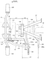
図1は本発明に係る自動二輪車の側面図であり、自動二輪車10に骨格となる車体フレーム11を備え、車体フレーム11は、前端を構成するヘッドパイプ12と、このヘッドパイプ12から後方斜め下方に延びるメインフレーム13と、このメインフレーム13の後部から後方斜め上方に延びる左右一対のシートレール14,16(手前側の符号14のみ示す。)と、メインフレーム13の後端及びシートレール14,16の後端のそれぞれを連結する左右一対のサブフレーム17,18(手前側の符号17のみ示す。)と、メインフレーム13の後端部(シートレール14,16及びサブフレーム17,18のそれぞれとメインフレーム13との連結部の間の部分)から下方に延びるピボットプレート21とからなる。
The best mode for carrying out the present invention will be described below with reference to the accompanying drawings. The drawings are viewed in the direction of the reference numerals.
FIG. 1 is a side view of a motorcycle according to the present invention. A
自動二輪車10は、上記車体フレーム11と、ヘッドパイプ12に回転自在に支持されたステアリング軸25と、このステアリング軸25の上端に取付けられたバーハンドル26と、ステアリング軸25の下端に取付けられたフロンとフォーク27と、このフロンとフォーク27の下端に取付けられた前輪28と、メインフレーム13の下部及びピボットプレート21の前部で支持されたパワーユニット30と、ピボットプレート21にピボット軸32を介してスイング自在に取付けられたスイングアーム33と、このスイングアーム33の後端部に回転自在に取付けられた後輪34と、サブフレーム17,18のシートレール14,16への接続部とスイングアーム33とに渡して取付けられた左右一対のリヤクッションユニット36,36(手前側の符号36のみ示す。)と、ピボットプレート21の下端部に回動自在に取付けられたメインスタンド37と、パワーユニット30の下部左側に回動自在に取付けられたサイドスタンド38と、パワーユニット30の底部に取付けられたステップバー41とからなる。
The
パワーユニット30は、エンジン31と、このエンジン31の後部に一体的に連結された無段変速機43とからなる駆動源であり、エンジン31は、前方にほぼ水平に延びるシリンダ部44を備え、このシリンダ部44の一部を構成するシリンダヘッド45の上部に吸気装置46が接続され、シリンダヘッド45の下部に排気装置47が接続されている。
The
無段変速機43の側方には、エンジン31を始動させるキックペダル51が配置されている。
吸気装置46は、シリンダヘッド45側から順に接続された吸気マニホールド53、スロットルボディ54、コネクティングチューブ55、エアクリーナ56からなる。
排気装置47は、シリンダヘッド45側から順に接続された排気管57、マフラ58からなる。
A
The
The
図中の符号65はハンドルカバー、66は車体前部カバー、67はヘッドランプ、68はフロントフェンダ、71はシート、72はサイドカバー、73はテールランプ、74はリヤフェンダ、76は同乗者用ステップである。
In the figure,
図2は本発明に係る自動二輪車の要部を示す側面図であり、メインフレーム13に左右一対のエンジンハンガ81,81(手前側の符号81のみ示す。)が取付けられ、パワーユニット30に備えるクランクケース83の上部及び後部にそれぞれパワーユニット側取付部83a,83b,83cが形成され、これらのパワーユニット側取付部83a,83b,83cがエンジンハンガ81,81及びピボットプレート21に取付けられている。
FIG. 2 is a side view showing a main part of the motorcycle according to the present invention. A pair of left and right engine hangers 81 (81 only shown) is attached to the
無段変速機43は、エンジン31のクランク軸85に取付けられた駆動プーリ86と、クランクケース83に回転自在に取付けられた従動軸87と、この従動軸87に取付けられた従動プーリ88と、これらの駆動プーリ86及び従動プーリ88のそれぞれに渡して掛けられたベルト91と、従動軸87に減速ギヤ(不図示)を介して連結された出力軸92とからなる。
The continuously
出力軸92にはドライブギヤ93が取付けられ、このドライブギヤ93と後輪34(図1参照)に一体的に設けられたドリブンギヤ94(図1参照)とにチェーン96(図1参照)が掛け渡されている。
A
メインスタンド37は、ピボットプレート21の下端部に支軸101を介して取付けられた筒状の軸支部102と、この軸支部102から延ばされた左右一対の脚部103,104(手前側の符号103のみ示す。)と、一方の脚部103にほぼ側方に延びるように取付けられた足掛け部106及び枝部107と、脚部103,104を立てられた状態又は跳ね上げて格納された状態に付勢するためにピボットプレート21側と脚部104とに掛け渡された引張コイルばね(不図示)とからなり、図2では、メインスタンド37が立てられた状態を示している。このとき、図1に示すように、後輪34は地面110から浮いた状態になっている。図2に戻って、符号111,112は左右の脚部103,104を連結する連結板及び連結パイプ、113は脚部103と足掛け部106とに渡された補強板である。
The
サイドスタンド38は、クランクケース83の左側下部に取付けられたベース部材115に支軸116を介して回動自在に取付けられた軸支部117と、この軸支部117に取付けられたアーム部118と、ベース部材115に設けられたピン121及びアーム部118に設けられたばね掛け部122のそれぞれに掛け渡された引張コイルばね123とからなり、図2では、サイドスタンド38が跳ね上げられて格納された状態を示している。なお、118aはアーム部118の先端に設けられた折曲げ部であり、接地する部分である。
The side stand 38 includes a
ステップバー41は、その両端部に、運転者が足を載せる左右一対のゴム製のステップ本体125,125(手前側の符号125のみ示す。)を備える。
キックペダル51は、クランクケース83の内側から延びてクランクケース83の左方に突出するキック軸127に取付けられたアーム部131と、このアーム部131に所定の角度範囲で回動自在に取付けられたペダル部132と、このペダル部132に一体に且つアーム部131に対してペダル部132とは反対の側に設けられた当接部133とからなる。
The
The
キック軸127は、複数のギヤを介してクランク軸85に連結され、キックペダル51を踏み込むことで、キック軸127が回動し、この回動により複数のギヤを介してクランク軸85が回転し、エンジン31が始動する。
The
キックペダル51のアーム部131は、キック軸127に近い位置に設けられた第1屈曲部131aと、この第1屈曲部131aよりもキック軸127から遠い位置に設けられた第2屈曲部131bとを備える。
The
第1屈曲部131aは、運転者がステップバー41、詳しくは、ステップバー41のステップ本体125に足を載せたときに足がアーム部131に干渉しないように折り曲げられた部分である。
第2屈曲部131bは、ペダル部132の位置を調整するために設けられた部分である。
The first
The second
当接部133は、ペダル部132の延長線上に形成された延長部133aと、この延長部133aからアーム部131に沿うようにキック軸127側にほぼ直角に曲げられた第1曲げ部133bと、この第1曲げ部133bからアーム部131に接近するように斜めに曲げられた第2曲げ部133cとからなる。
The
ペダル部132及び当接部133は、エンジン始動時以外は、運転者の邪魔にならないように図に示したようにキック軸127に直交する平面にほぼ沿うように格納されている。
The
以上に述べたキック始動式自動二輪車の作用を次に説明する。
図3は本発明に係るキック始動式自動二輪車のキックペダルの作用を示す第1作用図である。
エンジンを始動する場合には、キックペダル51のペダル部132を手前側に回動させてペダル部132が水平になるようにし、ペダル部132に足135を掛け、図の矢印の向きに踏み降ろす。図中の51Aは踏み降ろされる途中のキックペダル、51Bは踏み降ろされて回動範囲の終点に達したキックペダルを示している。(キックペダル51A,51Bはキックペダル51と同一のものであるが、説明の都合上、符号を変えている。)
このとき、キックペダル51は、メインスタンド37、サイドスタンド38の手前側を干渉なく踏み降ろされる。
Next, the operation of the kick start type motorcycle described above will be described.
FIG. 3 is a first operation diagram showing the operation of the kick pedal of the kick start type motorcycle according to the present invention.
When starting the engine, the
At this time, the
このときにエンジンが始動しても、図1に示したように、メインスタンド37が起立した状態にあり、後輪34は接地していないため、エンジン31から無段変速機43を介して後輪34に駆動力が伝わっても、後輪34は空転するだけであり、車両が発進することはない。
Even if the engine is started at this time, as shown in FIG. 1, the
図4は本発明に係るキック始動式自動二輪車の作用を示す第2作用図であり、図2でエンジン31が始動した後に、メインスタンド37を跳ね上げて所定位置に格納させた状態を示している。これで、自動二輪車10の走行状態に移ることができる。
FIG. 4 is a second operation diagram showing the operation of the kick start type motorcycle according to the present invention. FIG. 4 shows a state where the
図5は本発明に係るキック始動式自動二輪車のメインスタンド及びキックペダルの作用を示す第3作用図である。
例えば、キックによるエンジン始動時にメインスタンド37が跳ね上げられた状態にあると、矢印で示すように、足135でキックペダル51を踏んだときに、キックペダル51の当接部133が図の51Cの位置でメインスタンド37の枝部107に干渉する。(キックペダル51Cはキックペダル51と同一のものであるが、説明の都合上、符号を変えている。)
この状態を次図で詳細に説明する。
FIG. 5 is a third operation view showing the operation of the main stand and kick pedal of the kick start type motorcycle according to the present invention.
For example, when the
This state will be described in detail with reference to the next figure.
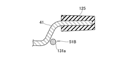
図6は本発明に係るキック始動式自動二輪車のキックペダルの作用を示す第4作用図(平面図)である。
踏み降ろした直後のキックペダル51の当接部133は、メインスタンド37の枝部107の先端部に当たる。この結果、キックペダル51の回動が阻止されるとともに、キックペダル51を踏み降ろすときの抵抗感によってメインスタンド37が格納状態にあることが運転者に認識される。
FIG. 6 is a fourth action diagram (plan view) showing the action of the kick pedal of the kick start type motorcycle according to the present invention.
The
このように、メインスタンド37とキックペダル51とが前後方向に大きく離れ、即ち、キック軸127に対してメインスタンド37が車両後方に大きい距離L1(L1はメインスタンド37の支軸101とキック軸127との距離)だけ離れ、キックペダル51のペダル部132よりも車両後方に後輪34の前端34aが位置し、更に、メインスタンド37とキックペダル51との間にサイドスタンド38が配置されることでメインスタンド37とキックペダル51とが車幅方向に大きく離れ、メインスタンド37の足掛け部106とキックペダル51とが前後方向に離れているような自動二輪車10(図1参照)では、従来のように、メインスタンドの足掛け部にキックペダルを当てることは難しい。
In this way, the
そこで、本発明では、スクータ型自動二輪車とは異なる自動二輪車10において、メインスタンド37に側方にほぼ直線状に延びる枝部107を設け、キックペダル51に当接部133を設けることで、当接部133を枝部107に当てて、キックペダル51の回動をメインスタンド37で容易に阻止することができる。
Therefore, in the present invention, in the
しかも、枝部107の先端部107aが当接部133に当たる位置とメインスタンド37の支軸101との距離L2は、足掛け部106の先端部106aと支軸101との距離L3よりも短いため、メインスタンド37を格納状態へ付勢する引張コイルばねの弾性力に抗して当接部133を押し下げる際に、足掛け部106でメインスタンド37を回動させるために必要なモーメントよりも、枝部107でメインスタンド37を回動させるために必要なモーメントの方が大きくなり、キックペダル51の回動をメインスタンド37でより確実に阻止することができる。
Moreover, since the distance L2 between the position where the
また、当接部133は、アーム部131に対してペダル部132とは反対方向に延びるため、ペダル部132に足を掛けるときには当接部133が車体内方を向くため、特別に当接部133を車体内方に向ける操作を必要としない。
更に、当接部133に第2曲げ部133cを形成することで、当接部133と、格納状態にあるサイドスタンド38の折曲げ部118aとの干渉を防止することができる。
Further, since the abutting
Furthermore, by forming the second
図7は本発明に係るキック始動式自動二輪車のキックペダルの作用を示す第5作用図であり、図3に示されたキックペダル51Bとステップバー41との位置関係を示している。即ち、回動範囲の終点までキックされたキックペダル51Bには第1屈曲部131aが設けられることで、キックペダル51Bとステップバー41との干渉を防止することができる。
FIG. 7 is a fifth action diagram showing the action of the kick pedal of the kick start type motorcycle according to the present invention, and shows the positional relationship between the
以上の図2、図6に示したように、本発明は、車体フレーム11に、エンジン31及びこのエンジン31の後部に一体的に連結された無段変速機43からなるパワーユニット30が支持され、車体フレーム11にスイングアーム33を介して支持される後輪34(図1参照)とメインスタンド37とが取付けられ、パワーユニット30の側部にキックペダル51が取付けられ、平面視でこれらのメインスタンド37及びキックペダル51のそれぞれの間にサイドスタンド38が配置され、メインスタンド37に、車体フレーム11に回動自在に支持された軸支部102とこの軸支部102から延ばされた脚部103,104とこれらの脚部103,104から車体側方に延びる足掛け部106とを備え、キックペダル51に、パワーユニット30側の回動軸としてのキック軸127に取付けられたアーム部131とこのアーム部131に取付けられたペダル部132とを備えたキック始動式自動二輪車10(図1参照)において、キックペダル51に、アーム部131に対してペダル部132とは反対方向に延びる当接部133が設けられ、メインスタンド37を立てて車体を支持した状態から跳ね上げた状態にして、エンジン31で駆動される後輪34を接地させたときに、キックされたキックペダル51の当接部133がメインスタンド37の一部と当たるようにしたので、レイアウト上、メインスタンド37とキックペダル51との位置が車両前後方向に大きく離れ、且つメインスタンド37とキックペダル51との間にサイドスタンド38が配置されている場合でも、跳ね上げて格納状態にされたメインスタンド37の一部にキックペダル51の当接部133を当てるようにして、キックペダル51の回動を阻止することができ、キックによるエンジン始動を防止し、自動二輪車10の運転者が意図せぬ発進を回避することができる。
As shown in FIGS. 2 and 6, in the present invention, the
また本発明は、メインスタンド37の脚部103に当接部133が当接可能な枝部107を備えるので、メインスタンド37とキックペダル51とが離れていても、当接部133と枝部107とでメインスタンド37の跳ね上げ時にキックペダル51による始動を容易に防止することができる。
Moreover, since the present invention includes the
更に本発明は、図2及び図7に示したように、運転者が足135を掛けるためにエンジン31の下部から側方に延びるステップバー41が設けられ、アーム部131に、キックペダル51をキックしたときにステップバー41との干渉を避けるための屈曲部としての第1屈曲部131aが設けられているので、キックペダル51の十分な回動範囲を確保しつつステップバー41とキックペダル51との干渉を避けることができる。
Furthermore, as shown in FIGS. 2 and 7, the present invention is provided with a
また本発明は、図2に示したように、第1屈曲部131aが、ステップバー41に掛けた運転者の足135を避けるように曲げられているので、キックペダル51の十分な回動範囲を確保しつつキックペダル51が乗車した運転者の足135に当たらないようにすることができる。
Further, in the present invention, as shown in FIG. 2, the first
更に、キックペダル51のキック軸127が、無段変速機43の左側に突出するとともに無段変速機43に設けられた従動軸87の下方に設けられているので、キックペダル51の位置をより低くすることができ、キックを容易に行うことができる。
Further, since the
尚、本実施形態では、図2に示したように、キックペダル51の当接部133をペダル部132に一体に形成したが、これに限らず、キックペダル51のアーム部131に車体内方に突出するように設けてもよい。
In the present embodiment, as shown in FIG. 2, the
本発明は、スクータ型以外の自動二輪車に好適である。 The present invention is suitable for motorcycles other than the scooter type.
10…自動二輪車、11…車体フレーム、30…パワーユニット、31…エンジン、33…スイングアーム、34…後輪、37…メインスタンド、38…サイドスタンド、41…ステップバー、43…無段変速機、51…キックペダル、87…従動軸、102…軸支部、103,104…脚部、106…足掛け部、107…枝部、131…アーム部、131a…屈曲部(第1屈曲部)、132…ペダル部、133…当接部。
DESCRIPTION OF
Claims (5)
前記キックペダルに、前記アーム部に対して前記ペダル部とは反対方向に延びる当接部が設けられ、
前記メインスタンドを立てて前記車体を支持した状態から跳ね上げた状態にして、前記エンジンで駆動される後輪を接地させたときに、キックされた前記キックペダルの前記当接部が前記メインスタンドの一部と当たるようにしたことを特徴とするキック始動式自動二輪車。 A power unit composed of an engine and a continuously variable transmission integrally connected to a rear portion of the engine is supported on the body frame, and a rear wheel and a main stand supported on the body frame via a swing arm are attached. A kick pedal is attached to a side portion of the power unit, a side stand is disposed between each of the main stand and the kick pedal in a plan view, and a shaft support portion rotatably supported by the body frame on the main stand. And a leg portion extending from the shaft support portion and a footrest portion extending from the leg portion toward the vehicle body, and an arm portion attached to the pivot shaft on the power unit side and the arm portion on the kick pedal In a kick starter motorcycle with an attached pedal part,
The kick pedal is provided with an abutting portion extending in a direction opposite to the pedal portion with respect to the arm portion,
When the rear stand driven by the engine is grounded from the state where the main stand is raised and the vehicle body is supported, the contact portion of the kick pedal kicked is the main stand. A kick starter motorcycle characterized in that it hits a part of the motorcycle.
Priority Applications (1)
| Application Number | Priority Date | Filing Date | Title |
|---|---|---|---|
| JP2007292594A JP2009121237A (en) | 2007-11-09 | 2007-11-09 | Kick starter motorcycle |
Applications Claiming Priority (1)
| Application Number | Priority Date | Filing Date | Title |
|---|---|---|---|
| JP2007292594A JP2009121237A (en) | 2007-11-09 | 2007-11-09 | Kick starter motorcycle |
Publications (1)
| Publication Number | Publication Date |
|---|---|
| JP2009121237A true JP2009121237A (en) | 2009-06-04 |
Family
ID=40813677
Family Applications (1)
| Application Number | Title | Priority Date | Filing Date |
|---|---|---|---|
| JP2007292594A Pending JP2009121237A (en) | 2007-11-09 | 2007-11-09 | Kick starter motorcycle |
Country Status (1)
| Country | Link |
|---|---|
| JP (1) | JP2009121237A (en) |
Cited By (2)
| Publication number | Priority date | Publication date | Assignee | Title |
|---|---|---|---|---|
| JP2010236373A (en) * | 2009-03-30 | 2010-10-21 | Honda Motor Co Ltd | Motorcycle |
| JP2014162433A (en) * | 2013-02-27 | 2014-09-08 | Honda Motor Co Ltd | Saddle-riding type vehicle |
-
2007
- 2007-11-09 JP JP2007292594A patent/JP2009121237A/en active Pending
Cited By (2)
| Publication number | Priority date | Publication date | Assignee | Title |
|---|---|---|---|---|
| JP2010236373A (en) * | 2009-03-30 | 2010-10-21 | Honda Motor Co Ltd | Motorcycle |
| JP2014162433A (en) * | 2013-02-27 | 2014-09-08 | Honda Motor Co Ltd | Saddle-riding type vehicle |
Similar Documents
| Publication | Publication Date | Title |
|---|---|---|
| US7802646B2 (en) | Snow vehicle | |
| US20090212532A1 (en) | Side stand attaching structure for motorcycle, motorcycle and method for attaching levelable side stand to motorcycle | |
| JP2008296658A (en) | Vehicle | |
| JP4755637B2 (en) | Kick starter motorcycle | |
| TWI330157B (en) | ||
| JP2009121237A (en) | Kick starter motorcycle | |
| CN102001383B (en) | Protection cover of an engine shell for a straddle type vehicle | |
| JP4499620B2 (en) | Speed change operation device for vehicle | |
| CN109689486B (en) | Battery box for saddle-ride type vehicle | |
| JP5027025B2 (en) | Saddle riding | |
| JP2007106221A (en) | Motorcycle with pillion step and mudguard | |
| JP2009073308A (en) | Motorcycle exhaust system | |
| JP6534776B2 (en) | Saddle-ride type vehicle | |
| JP2009119924A (en) | bicycle | |
| JP2010159042A (en) | Motorcycle | |
| JP2019023018A (en) | Vehicle speed change mechanism | |
| JP2012206537A (en) | Footrest structure of motorcycle | |
| JPWO2019064514A1 (en) | Exhaust gas sensor mounting structure | |
| JP5246422B2 (en) | Motorcycle | |
| JP6166333B2 (en) | Harness guide structure for saddle-ride type vehicles | |
| JP4130005B2 (en) | Step bracket device for motorcycles | |
| JP2011202548A (en) | Kick pedal mechanism for saddle type vehicle | |
| JP4431107B2 (en) | Center stand mounting structure for motorcycles | |
| JP2009119914A (en) | Recumbent bicycle | |
| JP2015068420A (en) | Gear shifting operation mechanism for saddle-type vehicle-mounted power unit |