JP2009122402A - Improved LED display - Google Patents
Improved LED display Download PDFInfo
- Publication number
- JP2009122402A JP2009122402A JP2007296308A JP2007296308A JP2009122402A JP 2009122402 A JP2009122402 A JP 2009122402A JP 2007296308 A JP2007296308 A JP 2007296308A JP 2007296308 A JP2007296308 A JP 2007296308A JP 2009122402 A JP2009122402 A JP 2009122402A
- Authority
- JP
- Japan
- Prior art keywords
- light source
- light
- liquid crystal
- led display
- crystal cell
- Prior art date
- Legal status (The legal status is an assumption and is not a legal conclusion. Google has not performed a legal analysis and makes no representation as to the accuracy of the status listed.)
- Pending
Links
Images


Landscapes
- Liquid Crystal (AREA)
- Planar Illumination Modules (AREA)
Abstract
【課題】
赤色(R)、緑色(G)、青色(B)の三原色からなるLED素子を1ピクセル単位の光源として適宜配列した光源用基板とを備え、前記光源を点灯した状態で液晶セルによって各ピクセルの発光を制御するようにして、上記従来のLEDディスプレイの問題点を解消しようとするものである。
【解決手段】
表面に所定の間隔で縦もしくは横にストライプ状光源を配列した光源用基板と、少なくともその片面に配置した液晶セルとを備え、ストライプ状光源の端面から赤色(R)、緑色(G)、青色(B)の三原色の光を入光させ、かつストライプ状光源の外周面から光を放射させて、液晶セルを用いて制御するLEDディスプレイであって、
前記光源を全点灯しておき、その状態で液晶セルを駆動して光源からの光を通過または遮断することによって各ピクセルの発光を制御するようにしたことを特徴とする改良型LEDディスプレイ。
【選択図】 図4【Task】
A light source substrate in which LED elements composed of the three primary colors of red (R), green (G), and blue (B) are appropriately arranged as a light source in units of one pixel. The present invention intends to solve the problems of the conventional LED display by controlling the light emission.
[Solution]
A light source substrate on which a striped light source is arranged vertically or horizontally at a predetermined interval on the surface, and a liquid crystal cell disposed on at least one side thereof, and red (R), green (G), and blue from the end surface of the striped light source (B) an LED display that receives light of the three primary colors and controls the liquid crystal cell to emit light from the outer peripheral surface of the stripe light source,
An improved LED display characterized in that the light source is fully lit and the liquid crystal cell is driven in that state to control the light emission of each pixel by passing or blocking the light from the light source.
[Selection] Figure 4
Description
この発明は、液晶テレビジョンや液晶モニタ等として利用することができる改良型LED(発光ダイオード)ディスプレイに関するものである。 The present invention relates to an improved LED (light emitting diode) display that can be used as a liquid crystal television, a liquid crystal monitor, or the like.
従来のLEDディスプレイは、通常砲弾型等の単品の赤色(R)、緑色(G)、青色(B)の三原色からなるLEDを、電流の供給を制御することによって駆動させ、所定の発色を得るようになっている。 A conventional LED display is driven by controlling the supply of electric current to obtain a predetermined color by a single red (R), green (G), or blue (B) LED, which is usually a single bullet type. It is like that.
そのため、細密なドットのLEDパネルディスプレイを実現しようとすると、多数のLEDを搭載する基板が多層の回路基板となってしまう。また前記多層基板に接続するコントロール用基板に形成するパターンおよび回路が極めて複雑なものとなるという問題があった。
上述のような欠点は、砲弾型の単品の赤色(R)、緑色(G)、青色(B)の三原色からなるLEDを、より小型のチップLEDで構成した場合においても、同様に抱えているものであった。
また、単品のLEDを利用した場合には、そのサイズは赤色(R)、緑色(G)、青色(B)1パッケイジの最小LEDでも3ミリ角程度の小型化が限界であり、電流調整回路のパターンが必要上、ピクセル単位を10mm角程度とする粗いLEDディスプレイしか作ることはできなかった。
Therefore, if an LED panel display with fine dots is to be realized, a board on which a large number of LEDs are mounted becomes a multilayer circuit board. In addition, there is a problem that a pattern and a circuit formed on the control substrate connected to the multilayer substrate are extremely complicated.
The above-mentioned drawbacks are similarly held even when a single bullet-type LED made of red (R), green (G), and blue (B) is composed of smaller chip LEDs. It was a thing.
In addition, when a single LED is used, the size of red (R), green (G), and blue (B) 1-package minimum LEDs is limited to downsizing by about 3 mm square. Therefore, only a rough LED display having a pixel unit of about 10 mm square can be produced.
そこで本発明者は先に特願2006−325024号において、上述した欠点を解消するために、赤色(R)、緑色(G)、青色(B)の三原色からなるLED素子を1ピクセル単位の光源として適宜配列した光源用基板と、少なくともその片面に配置した液晶セルとを備え、前記光源を全点灯しておき、その状態で液晶セルによって各ピクセルの発光を制御するようにして、上記従来の問題点を解消したLEDディスプレイを提案した。
しかしながら前記特願2006−325024号の発明においては、前記赤色(R)、緑色(G)、青色(B)の三原色からなるLED素子を1ピクセル単位の光源として適宜配列した光源用基板を使用しているため、LED素子が多数必要であり、また各素子間の接続等にも手間がかかってコスト低減が図り難いという問題があった。 However, in the invention of the Japanese Patent Application No. 2006-325024, a light source substrate in which LED elements composed of the three primary colors of red (R), green (G), and blue (B) are appropriately arranged as a light source in units of one pixel is used. Therefore, a large number of LED elements are required, and there is a problem that it is difficult to reduce costs because it takes time to connect the elements.
そこでこの発明は、表面に所定の間隔で縦もしくは横にストライプ状光源を配列した光源用基板と、少なくともその片面に配置した液晶セルとを備え、ストライプ状光源の端面から赤色(R)、緑色(G)、青色(B)の三原色の光を入光させ、かつストライプ状光源の外周面から光を放射させて、液晶セルを用いて制御するLEDディスプレイであって、
前記光源を全点灯しておき、その状態で液晶セルを駆動して光源からの光を通過または遮断することによって各ピクセルの発光を制御するようにして、より改良されたLEDディスプレイを提案しようとするものである。
こうすることによって、
1) より小さいサイズのピクセルをカバーすることができる
2) 大幅なコストダウンを図ることができる
顕著な効果を奏する改良型LEDディスプレイが達成できたのである。
Accordingly, the present invention includes a light source substrate in which stripe light sources are arranged vertically or horizontally at predetermined intervals on the surface, and a liquid crystal cell disposed on at least one surface thereof, and red (R) and green colors are formed from the end surfaces of the stripe light sources. (G), an LED display that controls the liquid crystal cell by making light of three primary colors of blue (B) incident and emitting light from the outer peripheral surface of the stripe light source,
In order to propose a more improved LED display, the light source is fully lit and the light emission of each pixel is controlled by driving the liquid crystal cell in that state to pass or block the light from the light source. To do.
By doing this,
1) It is possible to cover smaller sized pixels. 2) An improved LED display with a significant effect that can achieve a significant cost reduction has been achieved.
すなわち、この発明における改良型LEDディスプレイは、表面に所定の間隔で縦もしくは横にストライプ状光源を配列した光源用基板と、少なくともその片面に配置した液晶セルとを備え、ストライプ状光源の端面から赤色(R)、緑色(G)、青色(B)の三原色の光を入光させ、かつストライプ状光源の外周面から光を放射させて、液晶セルを用いて制御するLEDディスプレイであって、
前記光源を全点灯しておき、その状態で液晶セルを駆動して光源からの光を通過または遮断することによって各ピクセルの発光を制御するようにしたことを特徴とするものである。
That is, the improved LED display according to the present invention comprises a light source substrate in which striped light sources are arranged vertically or horizontally at predetermined intervals on the surface, and a liquid crystal cell disposed on at least one surface thereof, from the end surface of the striped light source. An LED display in which light of three primary colors of red (R), green (G), and blue (B) is incident, and light is emitted from the outer peripheral surface of the stripe light source, and is controlled using a liquid crystal cell,
The light source is fully lit, and the liquid crystal cell is driven in this state to control the light emission of each pixel by passing or blocking the light from the light source.
この発明における改良型LEDディスプレイは、前記ストライプ状光源の外周面に長さ方向に沿って所定の間隔で所定角度の切込みを形成することにより、ストライプ状光源を経由して該切込みに反射した光を前記ストライプ状光源の外周面から液晶セルに照射させる構造を採用したことをも特徴とするものである。 In the improved LED display according to the present invention, the light reflected by the cut light source via the stripe light source is formed by forming cuts of a predetermined angle at predetermined intervals along the length direction on the outer peripheral surface of the stripe light source. Further, the present invention is characterized by adopting a structure in which the liquid crystal cell is irradiated from the outer peripheral surface of the stripe light source.
この発明における改良型LEDディスプレイは、前記ストライプ状光源が光ファイバからなることをも特徴とするものである。 The improved LED display according to the present invention is characterized in that the striped light source is made of an optical fiber.
この発明における改良型LEDディスプレイは、前記ストライプ状光源が線状の光導波路からなることをも特徴とするものである。 The improved LED display according to the present invention is also characterized in that the striped light source comprises a linear optical waveguide.
この発明における改良型LEDディスプレイは、表面に所定の間隔で縦もしくは横にストライプ状光源を配列した光源用基板と、少なくともその片面に配置した液晶セルとを備え、ストライプ状光源の端面から赤色(R)、緑色(G)、青色(B)の三原色の光を入光させ、かつその外周面から光を放射させて、液晶セルを用いて制御するLEDディスプレイであって、前記光源を全点灯しておき、その状態で液晶セルによって各ピクセルの発光を制御するようにしたことにより、次のような効果を奏するものとなった。
1:液晶セルを用いているため、LCD製造インフラが利用でき、現状のコントロール用基板を流用できるので、部材のコストが非常に低廉である。
2:LEDディスプレイはストライプ状光源で赤色(R)、緑色(G)、青色(B)の三原色を実現して1ピクセル単位の光源とし、その外周面から光を放射させて、液晶セルを用いて制御するLEDディスプレイであって、ストライプ状光源に所定の間隔で切込みを入れて点発光させる点発光型ストライプ状光源を用いているので、単品のLEDを利用した場合のようなサイズ上の問題がなく、大幅な小型化を可能とすることができる。
3:液晶セル部分にカラーフィルターを使用しないので光の透過率が高く、駆動方式がカラーフィルターを使用する場合と同じであり、色割れが生じない。
4:単品のLEDを利用した場合に比べ、低温特性が確保できる。
5:光源を全点灯しておき、その状態で液晶セルを駆動して光源からの光を通過または遮断することによって各ピクセルの発光を制御するようにしたので、光を透過させない領域の光をカットし、使っている領域に光を際立たせることにより、光利用効率が大幅に向上する。
6:1ピクセルごとに必要であった高価なLED素子を大幅に削減することができるので、顕著なコストダウンを図ることができる。
The improved LED display according to the present invention includes a light source substrate in which stripe light sources are arranged vertically or horizontally at predetermined intervals on a surface, and a liquid crystal cell disposed on at least one surface thereof. An LED display that uses a liquid crystal cell to input light of the three primary colors of R), green (G), and blue (B) and emit light from the outer peripheral surface of the LED. In addition, since the light emission of each pixel is controlled by the liquid crystal cell in that state, the following effects can be obtained.
1: Since the liquid crystal cell is used, the LCD manufacturing infrastructure can be used, and the current control substrate can be used, so the cost of the member is very low.
2: The LED display is a striped light source that realizes the three primary colors of red (R), green (G), and blue (B) to form a light source in units of one pixel, and emits light from its outer peripheral surface, using a liquid crystal cell The LED display is controlled by a point light emitting stripe light source that makes point emission by cutting the stripe light source at a predetermined interval. Therefore, there is a size problem when using a single LED. There can be no significant downsizing.
3: Since a color filter is not used in the liquid crystal cell portion, the light transmittance is high, and the driving method is the same as when a color filter is used, and color breakup does not occur.
4: Low temperature characteristics can be ensured as compared to the case of using a single LED.
5: Since the light source is fully lit and the liquid crystal cell is driven in that state to control the light emission of each pixel by passing or blocking the light from the light source. By cutting and highlighting the light in the area where it is used, the light utilization efficiency is greatly improved.
Since expensive LED elements required for every 6: 1 pixel can be greatly reduced, a significant cost reduction can be achieved.
以下、この発明のLEDディスプレイの実施の形態について、図面に基づいて詳細に説明する。
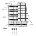
図1は、本発明のLEDディスプレイの参考例を示す平面図、図2は本発明のLEDディスプレイの第1実施例を示す斜視図、図3は本発明のLEDディスプレイの第2実施例を示す斜視図、図4は光ファイバもしくは光導波路の光照射部を形成した状態の概略説明図である。
Hereinafter, embodiments of the LED display of the present invention will be described in detail with reference to the drawings.
FIG. 1 is a plan view showing a reference example of the LED display of the present invention, FIG. 2 is a perspective view showing a first embodiment of the LED display of the present invention, and FIG. 3 shows a second embodiment of the LED display of the present invention. FIG. 4 is a schematic explanatory view of a state in which a light irradiation part of an optical fiber or an optical waveguide is formed.
図1の参考例において、11は赤色(R)、緑色(G)、青色(B)の三原色からなるLED素子を1ピクセル単位の光源として適宜配列した光源用基板である。また12は、少なくとも光源用基板11の片面に配置した液晶セルであり、前記光源を全点灯しておき、その状態で液晶セル12によって各ピクセルの発光を制御するようになっている。
その際、前記光源を全点灯しておき、その状態で液晶セル12によって各ピクセルの発光を制御するようにすれば、電流制御の場合のような複雑な回路や制御のための機構を不要とすることができる。
前記液晶セル12の駆動は、液晶セル12の画素の1つ1つにスイッチング素子と付加容量を接続し、これを介して各画素を制御するアクティブマトリックス駆動とすることが望ましい。すなわち、前記液晶セル12は赤色(R)、緑色(G)、青色(B)の三原色からなる各画素ごとに開閉可能となっており、開閉部位を制御することによって所定の発色を得るようにしたものである。
もちろん、他の駆動方式であっても良い。
In the reference example of FIG. 1, reference numeral 11 denotes a light source substrate in which LED elements composed of the three primary colors of red (R), green (G), and blue (B) are appropriately arranged as a light source in units of one pixel. Reference numeral 12 denotes a liquid crystal cell disposed on at least one surface of the light source substrate 11. The light source is fully lit, and the light emission of each pixel is controlled by the liquid crystal cell 12 in this state.
At that time, if the light source is fully turned on and the light emission of each pixel is controlled by the liquid crystal cell 12 in that state, a complicated circuit and a control mechanism as in the case of current control are unnecessary. can do.
The liquid crystal cell 12 is preferably driven by active matrix driving in which a switching element and an additional capacitor are connected to each pixel of the liquid crystal cell 12 and each pixel is controlled via the switching element. That is, the liquid crystal cell 12 can be opened and closed for each pixel composed of the three primary colors of red (R), green (G), and blue (B), and a predetermined color can be obtained by controlling the opening and closing parts. It is a thing.
Of course, other driving methods may be used.
図2の第1実施例において、21は合成樹脂材料22を基体とし、光ファイバを光導波路23として内部に位置決めした光源用基板である。図示した例では光導波路23として光ファイバを用いており、例えば所定の間隔で治具等により金型内に光ファイバを整列しておき、その上で金型内に合成樹脂を射出して成形することにより、光源用基板21内に所定の間隔で光ファイバをストライプ状に埋設した光源用基板21を得ることができる。 In FIG. 2, reference numeral 21 denotes a light source substrate having a synthetic resin material 22 as a base and an optical fiber as an optical waveguide 23 positioned inside. In the illustrated example, an optical fiber is used as the optical waveguide 23. For example, optical fibers are aligned in a mold with a jig or the like at a predetermined interval, and then a synthetic resin is injected into the mold and molded. By doing so, it is possible to obtain the light source substrate 21 in which the optical fibers are embedded in stripes in the light source substrate 21 at a predetermined interval.
前記光源用基板21に所定の間隔で配設した光ファイバからなる光導波路23には、それぞれ順次その片側もしくは両側の端面から赤色(R)、緑色(G)、青色(B)の三原色の光を入光させる。24は、少なくとも光源用基板21の片面に配置した液晶セルであり、前記光源を点灯しておき、その状態で液晶セル24によって各ピクセルの発光を制御するようになっている。
なお、光ファイバからなる光導波路23の片側から赤色(R)、緑色(G)、青色(B)の三原色の光を入光させる場合には、他端には反射面を形成しておけばよい。
The light guides 23 made of optical fibers disposed on the light source substrate 21 at predetermined intervals sequentially receive light of three primary colors of red (R), green (G), and blue (B) from the end surfaces on one side or both sides. Light up. Reference numeral 24 denotes a liquid crystal cell disposed on at least one surface of the light source substrate 21. The light source is turned on, and the light emission of each pixel is controlled by the liquid crystal cell 24 in this state.
If light of the three primary colors red (R), green (G), and blue (B) is incident from one side of the optical waveguide 23 made of an optical fiber, a reflection surface should be formed at the other end. Good.
前記入光部25の構造は、光ファイバを用いて前記光源用基板21に所定の間隔で配設した光導波路23にコネクタや接着剤で接続しても、またそれ以外の方法で入光部25を形成してもよいことはもちろんである。
ちなみに、入光部25においては、赤色(R)、緑色(G)、青色(B)の三原色の光は1つの光源を分岐させた上、前記各光ファイバまたは光導波路23に入光させることができる。
The structure of the light incident part 25 is such that the light incident part 25 can be connected to the optical waveguide 23 disposed at a predetermined interval on the light source substrate 21 using an optical fiber, or by other methods. Of course, 25 may be formed.
Incidentally, in the light incident part 25, the light of the three primary colors of red (R), green (G), and blue (B) is made to enter each optical fiber or optical waveguide 23 after branching one light source. Can do.
入光部25から入射した光は、光源用基板21において所定の間隔で配設した光ファイバからなる光導波路23の外周部分において、光源用基板21の面からそれぞれ放散され、赤色(R)、緑色(G)、青色(B)の三原色の光をストライプ状に発光させるようになるのである。
その際、前記ストライプ状光源を点灯しておき、その状態で液晶セル24によって各ピクセルの発光を制御するようにすれば、電流制御の場合のような複雑な回路や制御のための機構を不要とすることができる。
The light incident from the light incident portion 25 is diffused from the surface of the light source substrate 21 at the outer peripheral portion of the optical waveguide 23 made of optical fibers disposed at a predetermined interval in the light source substrate 21, and red (R), The light of the three primary colors of green (G) and blue (B) is emitted in stripes.
At that time, if the stripe light source is turned on and the light emission of each pixel is controlled by the liquid crystal cell 24 in that state, a complicated circuit and a control mechanism as in the case of current control are unnecessary. It can be.
図3の第2実施例において、31はガラス材料32を基体とし、レーザ光の集光照射によって屈折率を変化させた部分を光導波路33として内部に形成した光源用基板である。
前記光導波路33を用いる場合には、光導波路の外周面をレンズ状に形成し、そのレンズ部分を光源用基板31の表面に所定の間隔で配列すればよい。
In the second embodiment of FIG. 3, reference numeral 31 denotes a light source substrate having a glass material 32 as a base and a portion whose refractive index is changed by condensing irradiation of laser light as an optical waveguide 33.
When the optical waveguide 33 is used, the outer peripheral surface of the optical waveguide may be formed in a lens shape, and the lens portions may be arranged on the surface of the light source substrate 31 at a predetermined interval.
34は、少なくとも光源用基板31の片面に配置した液晶セルであり、前記光導波路33を点灯しておき、その状態で液晶セル34によって各ピクセルの発光を制御するようになっている。
そうすることにより、電流制御の場合のような複雑な回路や制御のための機構を不要とすることができる。
Reference numeral 34 denotes a liquid crystal cell disposed on at least one surface of the light source substrate 31. The light guide 33 is turned on, and the light emission of each pixel is controlled by the liquid crystal cell 34 in this state.
By doing so, a complicated circuit and a mechanism for control as in the case of current control can be eliminated.
なお、上記第2実施例および第3実施例においては、光ファイバからなる光導波路23,光導波路33の径によって単位ピクセルのサイズも変わることになり、光導波路23,33を細くすることによって単位ピクセルの大きさを飛躍的に小さくすることができるようになる。 In the second and third embodiments, the size of the unit pixel also changes depending on the diameters of the optical waveguide 23 and the optical waveguide 33 made of optical fibers. The pixel size can be dramatically reduced.
図4(a)および(b)は、入光部45から入射した光を、光源用基板41に所定の間隔で配設したストライプ状光源を構成する光ファイバ等からなる光導波路42の外周部分を経由して、光源用基板41の表面からそれぞれ放散させる具体的な構造を説明するためのものである。
すなわち、光導波路42に、その長さ方向に沿って所定の間隔で所定角度の切込み43を形成することにより、該切込み43において反射した光を前記切込み43とは反対側の光導波路42の外周面から液晶セル44に向けて照射させるようになっている。
この切込み43のV字形の角度や、ストライプ状光源を構成する光ファイバ等からなる光導波路42内における切込み深さ等は、それらに採用された素材の光の屈折率や光ファイバ等からなる光導波路42の径等に応じて適宜決定することができる。
4 (a) and 4 (b) show an outer peripheral portion of an
That is, the
The V-shaped angle of the
以上述べた構成のLEDディスプレイ、また該LEDディスプレイを適用した液晶テレビジョンや液晶モニタの作用・効果について説明する。
1:液晶セルを用いているため、LCD製造インフラが利用でき、現状のコントロール用基板を流用できるので、部材のコストが非常に低廉である。
2:赤色(R)、緑色(G)、青色(B)の三原色からなるLED素子を1ピクセル単位の光源として所定の間隔で配列した光源用基板を用いているので、単品のLEDを利用した場合のようなサイズ上の問題がなく、大幅な小型化を可能とすることができる。
3:液晶セル部分にカラーフィルターを使用しないので光の透過率が高く、駆動方式がカラーフィルターを使用する場合と同じであり、色割れが生じない。
4:単品のLEDを利用した場合に比べ、色再現性が高い。
5:単品のLEDを利用した場合に比べ、低温特性が確保できる。
6:光源を全点灯しておき、その状態で液晶セルを駆動して光源からの光を通過または遮断することによって各ピクセルの発光を制御するようにしたので、光を透過させない領域の光をカットし、使っている領域に光を集中させることにより、光利用効率が大幅に向上する。
The operation and effect of the LED display having the above-described configuration, and a liquid crystal television and a liquid crystal monitor to which the LED display is applied will be described.
1: Since the liquid crystal cell is used, the LCD manufacturing infrastructure can be used, and the current control substrate can be used, so the cost of the member is very low.
2: Since a light source substrate in which LED elements composed of three primary colors of red (R), green (G), and blue (B) are arranged at predetermined intervals as a light source in units of one pixel is used, a single LED is used. There is no problem in size as in the case, and a significant reduction in size can be achieved.
3: Since a color filter is not used in the liquid crystal cell portion, the light transmittance is high, and the driving method is the same as when a color filter is used, and color breakup does not occur.
4: Color reproducibility is higher than when single LED is used.
5: Low temperature characteristics can be secured as compared with the case of using a single LED.
6: Since the light source is fully lit and the liquid crystal cell is driven in that state to control the light emission of each pixel by passing or blocking the light from the light source. By cutting and concentrating the light on the used area, the light utilization efficiency is greatly improved.
この発明のLEDディスプレイは以上のように構成したので、液晶テレビジョンや液晶モニタ等の代わりとしてのみならず、その他の液晶表示用のディスプレイの代わりとして幅広く利用することができる。 Since the LED display of the present invention is configured as described above, it can be widely used not only as a substitute for a liquid crystal television or a liquid crystal monitor but also as a substitute for other liquid crystal display.
11 光源用基板
12 液晶セル
21 光源用基板
22 ガラス材料
23 光導波路
24 液晶セル
25 入光部
31 光源用基板
32 ガラス材料
33 光導波路
34 液晶セル
41 光源用基板
42 光導波路
43 切込み
44 液晶セル
45 入光部
DESCRIPTION OF SYMBOLS 11 Light source substrate 12 Liquid crystal cell 21 Light source substrate 22 Glass material 23 Optical waveguide 24 Liquid crystal cell 25 Light receiving part 31 Light source substrate 32 Glass material 33 Optical waveguide 34
Claims (4)
前記光源を全点灯しておき、その状態で液晶セルを駆動して光源からの光を通過または遮断することによって各ピクセルの発光を制御するようにしたことを特徴とする改良型LEDディスプレイ。 A light source substrate on which a striped light source is arranged vertically or horizontally at a predetermined interval on the surface, and a liquid crystal cell disposed on at least one side thereof, and red (R), green (G), and blue from the end surface of the striped light source (B) an LED display that receives light of the three primary colors and controls the liquid crystal cell to emit light from the outer peripheral surface of the stripe light source,
An improved LED display characterized in that the light source is fully lit and the liquid crystal cell is driven in that state to control the light emission of each pixel by passing or blocking the light from the light source.
Priority Applications (2)
| Application Number | Priority Date | Filing Date | Title |
|---|---|---|---|
| JP2007296308A JP2009122402A (en) | 2007-11-15 | 2007-11-15 | Improved LED display |
| PCT/JP2007/001332 WO2008065758A1 (en) | 2006-11-30 | 2007-11-30 | Improved type led display |
Applications Claiming Priority (1)
| Application Number | Priority Date | Filing Date | Title |
|---|---|---|---|
| JP2007296308A JP2009122402A (en) | 2007-11-15 | 2007-11-15 | Improved LED display |
Publications (1)
| Publication Number | Publication Date |
|---|---|
| JP2009122402A true JP2009122402A (en) | 2009-06-04 |
Family
ID=40814616
Family Applications (1)
| Application Number | Title | Priority Date | Filing Date |
|---|---|---|---|
| JP2007296308A Pending JP2009122402A (en) | 2006-11-30 | 2007-11-15 | Improved LED display |
Country Status (1)
| Country | Link |
|---|---|
| JP (1) | JP2009122402A (en) |
Citations (4)
| Publication number | Priority date | Publication date | Assignee | Title |
|---|---|---|---|---|
| JPS62227118A (en) * | 1986-03-28 | 1987-10-06 | Biimu Soken:Kk | Thin type color display device |
| JPH10288782A (en) * | 1997-03-10 | 1998-10-27 | Nec Corp | Optical back light module for color display |
| JP2002196332A (en) * | 2000-12-01 | 2002-07-12 | Lumileds Lighting Us Llc | Color isolate backlight for lcd |
| JP2007156475A (en) * | 2006-11-30 | 2007-06-21 | E Image Technology Kk | LED display |
-
2007
- 2007-11-15 JP JP2007296308A patent/JP2009122402A/en active Pending
Patent Citations (4)
| Publication number | Priority date | Publication date | Assignee | Title |
|---|---|---|---|---|
| JPS62227118A (en) * | 1986-03-28 | 1987-10-06 | Biimu Soken:Kk | Thin type color display device |
| JPH10288782A (en) * | 1997-03-10 | 1998-10-27 | Nec Corp | Optical back light module for color display |
| JP2002196332A (en) * | 2000-12-01 | 2002-07-12 | Lumileds Lighting Us Llc | Color isolate backlight for lcd |
| JP2007156475A (en) * | 2006-11-30 | 2007-06-21 | E Image Technology Kk | LED display |
Similar Documents
| Publication | Publication Date | Title |
|---|---|---|
| US7708428B2 (en) | Backlight assembly and display device having the same | |
| KR100574206B1 (en) | Lighting device and liquid crystal display device | |
| JP4256738B2 (en) | Planar light source device and display device using the same | |
| KR101081171B1 (en) | Device for producing a bundled light flux | |
| JP2010021131A (en) | Display device and backlight unit used for the same | |
| US7708444B2 (en) | Surface light source device | |
| JP2010067439A (en) | Surface light-emitting device, and display device | |
| JP2012003263A (en) | Backlight unit and display device including the same | |
| JP6358894B2 (en) | Surface light source device and liquid crystal display device | |
| KR20080038925A (en) | Backlight source and lens for light source and backlight assembly comprising the same | |
| JP2006286906A (en) | Light emitting diode device, backlight device using the same, and liquid crystal display device | |
| EP2280217B1 (en) | Light unit with light guide plate and display apparatus having the same | |
| KR20170004205A (en) | Light guide plate and plane light source device having the same | |
| WO2012011304A1 (en) | Light guiding body, light source unit, illumination device, and display device | |
| WO2011111270A1 (en) | Light guide set, illumination device, and display device | |
| JP2012018308A (en) | Liquid crystal display device | |
| KR20070020725A (en) | Color filter-free liquid crystal display device | |
| CN1996129B (en) | Light source device and liquid crystal display device using the same | |
| US9989689B2 (en) | Backlight unit capable of local dimming | |
| TW201629551A (en) | Display device with directional control of the output, and a backlight for such a display device | |
| US20080291694A1 (en) | Planar light source device and display device | |
| KR100433218B1 (en) | Backlight unit | |
| JP4122503B2 (en) | LED display | |
| JP2009122402A (en) | Improved LED display | |
| KR101054385B1 (en) | Light guide plate and backlight unit having same |
Legal Events
| Date | Code | Title | Description |
|---|---|---|---|
| A621 | Written request for application examination |
Free format text: JAPANESE INTERMEDIATE CODE: A621 Effective date: 20101115 |
|
| A131 | Notification of reasons for refusal |
Free format text: JAPANESE INTERMEDIATE CODE: A131 Effective date: 20120605 |
|
| A521 | Written amendment |
Free format text: JAPANESE INTERMEDIATE CODE: A523 Effective date: 20120803 |
|
| A131 | Notification of reasons for refusal |
Free format text: JAPANESE INTERMEDIATE CODE: A131 Effective date: 20120822 |
|
| A02 | Decision of refusal |
Free format text: JAPANESE INTERMEDIATE CODE: A02 Effective date: 20121211 |