JP2009138580A - 燃料噴射弁及びそれを備えた燃料噴射装置 - Google Patents
燃料噴射弁及びそれを備えた燃料噴射装置 Download PDFInfo
- Publication number
- JP2009138580A JP2009138580A JP2007314267A JP2007314267A JP2009138580A JP 2009138580 A JP2009138580 A JP 2009138580A JP 2007314267 A JP2007314267 A JP 2007314267A JP 2007314267 A JP2007314267 A JP 2007314267A JP 2009138580 A JP2009138580 A JP 2009138580A
- Authority
- JP
- Japan
- Prior art keywords
- fuel
- pressure
- flow path
- valve
- fuel injection
- Prior art date
- Legal status (The legal status is an assumption and is not a legal conclusion. Google has not performed a legal analysis and makes no representation as to the accuracy of the status listed.)
- Pending
Links
Images




Classifications
-
- F—MECHANICAL ENGINEERING; LIGHTING; HEATING; WEAPONS; BLASTING
- F02—COMBUSTION ENGINES; HOT-GAS OR COMBUSTION-PRODUCT ENGINE PLANTS
- F02D—CONTROLLING COMBUSTION ENGINES
- F02D41/00—Electrical control of supply of combustible mixture or its constituents
- F02D41/30—Controlling fuel injection
- F02D41/3011—Controlling fuel injection according to or using specific or several modes of combustion
- F02D41/3017—Controlling fuel injection according to or using specific or several modes of combustion characterised by the mode(s) being used
- F02D41/3035—Controlling fuel injection according to or using specific or several modes of combustion characterised by the mode(s) being used a mode being the premixed charge compression-ignition mode
- F02D41/3041—Controlling fuel injection according to or using specific or several modes of combustion characterised by the mode(s) being used a mode being the premixed charge compression-ignition mode with means for triggering compression ignition, e.g. spark plug
- F02D41/3047—Controlling fuel injection according to or using specific or several modes of combustion characterised by the mode(s) being used a mode being the premixed charge compression-ignition mode with means for triggering compression ignition, e.g. spark plug said means being a secondary injection of fuel
-
- F—MECHANICAL ENGINEERING; LIGHTING; HEATING; WEAPONS; BLASTING
- F02—COMBUSTION ENGINES; HOT-GAS OR COMBUSTION-PRODUCT ENGINE PLANTS
- F02D—CONTROLLING COMBUSTION ENGINES
- F02D19/00—Controlling engines characterised by their use of non-liquid fuels, pluralities of fuels, or non-fuel substances added to the combustible mixtures
- F02D19/06—Controlling engines characterised by their use of non-liquid fuels, pluralities of fuels, or non-fuel substances added to the combustible mixtures peculiar to engines working with pluralities of fuels, e.g. alternatively with light and heavy fuel oil, other than engines indifferent to the fuel consumed
- F02D19/0602—Control of components of the fuel supply system
- F02D19/0607—Control of components of the fuel supply system to adjust the fuel mass or volume flow
- F02D19/061—Control of components of the fuel supply system to adjust the fuel mass or volume flow by controlling fuel injectors
-
- F—MECHANICAL ENGINEERING; LIGHTING; HEATING; WEAPONS; BLASTING
- F02—COMBUSTION ENGINES; HOT-GAS OR COMBUSTION-PRODUCT ENGINE PLANTS
- F02D—CONTROLLING COMBUSTION ENGINES
- F02D19/00—Controlling engines characterised by their use of non-liquid fuels, pluralities of fuels, or non-fuel substances added to the combustible mixtures
- F02D19/06—Controlling engines characterised by their use of non-liquid fuels, pluralities of fuels, or non-fuel substances added to the combustible mixtures peculiar to engines working with pluralities of fuels, e.g. alternatively with light and heavy fuel oil, other than engines indifferent to the fuel consumed
- F02D19/0626—Measuring or estimating parameters related to the fuel supply system
- F02D19/0628—Determining the fuel pressure, temperature or flow, the fuel tank fill level or a valve position
- F02D19/0631—Determining the fuel pressure, temperature or flow, the fuel tank fill level or a valve position by estimation, i.e. without using direct measurements of a corresponding sensor
-
- F—MECHANICAL ENGINEERING; LIGHTING; HEATING; WEAPONS; BLASTING
- F02—COMBUSTION ENGINES; HOT-GAS OR COMBUSTION-PRODUCT ENGINE PLANTS
- F02D—CONTROLLING COMBUSTION ENGINES
- F02D19/00—Controlling engines characterised by their use of non-liquid fuels, pluralities of fuels, or non-fuel substances added to the combustible mixtures
- F02D19/06—Controlling engines characterised by their use of non-liquid fuels, pluralities of fuels, or non-fuel substances added to the combustible mixtures peculiar to engines working with pluralities of fuels, e.g. alternatively with light and heavy fuel oil, other than engines indifferent to the fuel consumed
- F02D19/0663—Details on the fuel supply system, e.g. tanks, valves, pipes, pumps, rails, injectors or mixers
- F02D19/0673—Valves; Pressure or flow regulators; Mixers
- F02D19/0676—Multi-way valves; Switch-over valves
-
- F—MECHANICAL ENGINEERING; LIGHTING; HEATING; WEAPONS; BLASTING
- F02—COMBUSTION ENGINES; HOT-GAS OR COMBUSTION-PRODUCT ENGINE PLANTS
- F02D—CONTROLLING COMBUSTION ENGINES
- F02D19/00—Controlling engines characterised by their use of non-liquid fuels, pluralities of fuels, or non-fuel substances added to the combustible mixtures
- F02D19/06—Controlling engines characterised by their use of non-liquid fuels, pluralities of fuels, or non-fuel substances added to the combustible mixtures peculiar to engines working with pluralities of fuels, e.g. alternatively with light and heavy fuel oil, other than engines indifferent to the fuel consumed
- F02D19/0663—Details on the fuel supply system, e.g. tanks, valves, pipes, pumps, rails, injectors or mixers
- F02D19/0686—Injectors
- F02D19/0694—Injectors operating with a plurality of fuels
-
- F—MECHANICAL ENGINEERING; LIGHTING; HEATING; WEAPONS; BLASTING
- F02—COMBUSTION ENGINES; HOT-GAS OR COMBUSTION-PRODUCT ENGINE PLANTS
- F02D—CONTROLLING COMBUSTION ENGINES
- F02D19/00—Controlling engines characterised by their use of non-liquid fuels, pluralities of fuels, or non-fuel substances added to the combustible mixtures
- F02D19/06—Controlling engines characterised by their use of non-liquid fuels, pluralities of fuels, or non-fuel substances added to the combustible mixtures peculiar to engines working with pluralities of fuels, e.g. alternatively with light and heavy fuel oil, other than engines indifferent to the fuel consumed
- F02D19/08—Controlling engines characterised by their use of non-liquid fuels, pluralities of fuels, or non-fuel substances added to the combustible mixtures peculiar to engines working with pluralities of fuels, e.g. alternatively with light and heavy fuel oil, other than engines indifferent to the fuel consumed simultaneously using pluralities of fuels
- F02D19/10—Controlling engines characterised by their use of non-liquid fuels, pluralities of fuels, or non-fuel substances added to the combustible mixtures peculiar to engines working with pluralities of fuels, e.g. alternatively with light and heavy fuel oil, other than engines indifferent to the fuel consumed simultaneously using pluralities of fuels peculiar to compression-ignition engines in which the main fuel is gaseous
- F02D19/105—Controlling engines characterised by their use of non-liquid fuels, pluralities of fuels, or non-fuel substances added to the combustible mixtures peculiar to engines working with pluralities of fuels, e.g. alternatively with light and heavy fuel oil, other than engines indifferent to the fuel consumed simultaneously using pluralities of fuels peculiar to compression-ignition engines in which the main fuel is gaseous operating in a special mode, e.g. in a liquid fuel only mode for starting
-
- F—MECHANICAL ENGINEERING; LIGHTING; HEATING; WEAPONS; BLASTING
- F02—COMBUSTION ENGINES; HOT-GAS OR COMBUSTION-PRODUCT ENGINE PLANTS
- F02D—CONTROLLING COMBUSTION ENGINES
- F02D41/00—Electrical control of supply of combustible mixture or its constituents
- F02D41/0025—Controlling engines characterised by use of non-liquid fuels, pluralities of fuels, or non-fuel substances added to the combustible mixtures
-
- F—MECHANICAL ENGINEERING; LIGHTING; HEATING; WEAPONS; BLASTING
- F02—COMBUSTION ENGINES; HOT-GAS OR COMBUSTION-PRODUCT ENGINE PLANTS
- F02D—CONTROLLING COMBUSTION ENGINES
- F02D41/00—Electrical control of supply of combustible mixture or its constituents
- F02D41/30—Controlling fuel injection
- F02D41/38—Controlling fuel injection of the high pressure type
- F02D41/40—Controlling fuel injection of the high pressure type with means for controlling injection timing or duration
- F02D41/402—Multiple injections
-
- F—MECHANICAL ENGINEERING; LIGHTING; HEATING; WEAPONS; BLASTING
- F02—COMBUSTION ENGINES; HOT-GAS OR COMBUSTION-PRODUCT ENGINE PLANTS
- F02B—INTERNAL-COMBUSTION PISTON ENGINES; COMBUSTION ENGINES IN GENERAL
- F02B1/00—Engines characterised by fuel-air mixture compression
- F02B1/12—Engines characterised by fuel-air mixture compression with compression ignition
-
- Y—GENERAL TAGGING OF NEW TECHNOLOGICAL DEVELOPMENTS; GENERAL TAGGING OF CROSS-SECTIONAL TECHNOLOGIES SPANNING OVER SEVERAL SECTIONS OF THE IPC; TECHNICAL SUBJECTS COVERED BY FORMER USPC CROSS-REFERENCE ART COLLECTIONS [XRACs] AND DIGESTS
- Y02—TECHNOLOGIES OR APPLICATIONS FOR MITIGATION OR ADAPTATION AGAINST CLIMATE CHANGE
- Y02T—CLIMATE CHANGE MITIGATION TECHNOLOGIES RELATED TO TRANSPORTATION
- Y02T10/00—Road transport of goods or passengers
- Y02T10/10—Internal combustion engine [ICE] based vehicles
- Y02T10/30—Use of alternative fuels, e.g. biofuels
-
- Y—GENERAL TAGGING OF NEW TECHNOLOGICAL DEVELOPMENTS; GENERAL TAGGING OF CROSS-SECTIONAL TECHNOLOGIES SPANNING OVER SEVERAL SECTIONS OF THE IPC; TECHNICAL SUBJECTS COVERED BY FORMER USPC CROSS-REFERENCE ART COLLECTIONS [XRACs] AND DIGESTS
- Y02—TECHNOLOGIES OR APPLICATIONS FOR MITIGATION OR ADAPTATION AGAINST CLIMATE CHANGE
- Y02T—CLIMATE CHANGE MITIGATION TECHNOLOGIES RELATED TO TRANSPORTATION
- Y02T10/00—Road transport of goods or passengers
- Y02T10/10—Internal combustion engine [ICE] based vehicles
- Y02T10/40—Engine management systems
Landscapes
- Engineering & Computer Science (AREA)
- Chemical & Material Sciences (AREA)
- Combustion & Propulsion (AREA)
- Mechanical Engineering (AREA)
- General Engineering & Computer Science (AREA)
- Oil, Petroleum & Natural Gas (AREA)
- Fuel-Injection Apparatus (AREA)
- Output Control And Ontrol Of Special Type Engine (AREA)
Abstract
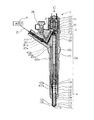
【解決手段】燃料噴射弁10は、高圧気体燃料GFの導入される高圧気体燃料導入流路362と、高圧液体燃料LFの導入される高圧液体燃料導入流路250と、ノズル部11内に設けた燃料室408と、高圧気体燃料導入流路362と燃料室408とを連通せしめる第1の流路と、高圧液体燃料導入流路250と燃焼室408とを連通せしめる第2の流路と、第1の流路と第2の流路とを切換える流路切換弁400とを具備する。
【選択図】図4
Description
燃料噴射装置1は、1つの燃料噴射弁10を気体燃料GFの噴射を担う気体燃料噴射系(GFIS)と液体燃料LFの噴射を担う液体燃料噴射系(LFIS)とによって共用している。
燃料噴射弁10は、燃料を筒内に直接噴射する多気筒圧内燃機関用の燃料噴射弁として構成され、1気筒当たりに1つの燃料噴射弁10が設けられている。
LFISは、LFタンク20、給液管21、23、高圧ポンプ22、LFコモンレール24、LF供給管25、LF圧力センサ26、安全弁27、LF回収管28、燃料噴射弁10、ECU40、EDU41によって構成されている。
LFタンク20から高圧ポンプ22によって汲み上げられた液体燃料LFは、LFコモンレール24に蓄圧され、複数の燃料噴射弁10に供給されている。
高圧GFタンク30から調圧弁32を介してGFコモンレール35に蓄圧された高圧気体燃料GFが複数の燃料噴射弁10に供給されている。燃料噴射弁10から液体燃料LFの一部がLF回収管28を介してLFタンク20に還流されている。
液体燃料LFは、着火性の低い気体燃料の着火性を向上する助燃料として用いられるだけでなく、燃料噴射弁10の駆動力を伝達する圧力伝達媒体並びに潤滑油としても用いられる。
ノズル部基体110は、中心に軸方向に伸びる縦穴がニードル摺動穴111として形成され、軸状に伸びるニードル120の摺動部121を摺動自在に保持し、底部114には、ニードル120の先端に設けられた弁部124離着座によって開閉する噴孔115が形成されている。
更に、ノズル部基体110には、一端がニードル摺動穴111に開口し、他端がノズル部基体110の上端面において開口しつつ、燃料供給流路405に連通する潤滑油供給流路406が穿設されている。
更に、ニードル120の基端側には、ニードル120と一体的に連動する制御ピストン126が燃料噴射弁基体100に形成された制御ピストン摺動穴101に摺動自在に配設されている。
ニードル摺動部121と同様に、制御ピストン126の摺動部127の外周には、複数の環状溝部212が形成され、気体燃料GFが環状溝部128に滞留して摺動部211を潤滑可能となっている。
背圧制御室130には、高圧の液体燃料LFが絞り流路131を介して導入され、高圧液体燃料LFの圧力が制御ピストン126の背面にニードル弁部124の閉弁方向に作用している。
制御ピストン126には、背圧制御室130内の液体燃料によって閉弁方向の圧力と、燃料室408内の燃料によってニードル120を介して開弁方向の圧力とが作用している。更に、制御ピストン126の中腹部外周に設けたスプリング室に配設されるリターンスプリングにより閉弁方向に付勢されている。
従って、制御ピストン126とニードル120とは、背圧制御室130内の液体燃料LFの圧力を増減することによって、上下動するようになっている。 なお、制御ピストン126のピストン軸部の周りに形成されたノズル基体100の内周壁との空隙には、カウンタバランス圧力を生む圧力伝達媒体として液体燃料LFが導入されている。
非通電時には、付勢バネ152によってアーマチャ151が閉弁方向に付勢され、アーマチャ151の先端に固定された制御弁体140によって、制御背圧室出口流路132が閉弁されている。一方、通電時にはソレノイド150が励磁され、アーマチャ151が付勢バネ152のバネ圧に抗して引き上げられ、制御背圧室出口流路132が開弁される。
なお、アーマチャ151の上下の空間にはカウンタバランス圧力を作用させるために開放流路281と連通した状態で液体燃料LFが導入されている。
ECU40から指令に従って、ソレノイド150に通電されると、ソレノイド150が励磁し、付勢バネ152のバネ力に抗して、アーマチャ151が引き上げられる。これに連動して制御弁体140が引き上げられ、背圧制御室130の出口流路131が開口し、背圧制御室130内の気体燃料GFが、出口流路131を通って、開放流路281、280から流出され、背圧制御室130内の圧力が下がり、制御ピストン126及びニードル120が上昇し、噴孔115が開口し、燃料室408から高圧の燃料が噴射される。
切換弁位置1では、第1の流路として、第1のポートP1と第3のポートP3とが連通し、高圧GF導入流路362と燃料室408とが連通し、第2の切換弁位置では、第2の流路として、第2のポートP2と第3のポートP3とが連通し、高圧LF導入流路260と燃料室408とが連通する。
本図(b)に示すように、ソレノイド410が励磁されていない切換弁位置1の場合には、バネ411が、弁体413を第2のポートP2の閉弁方向に付勢し、第1のポートP1と第3のポートP3とが切換弁室363、連通路364、切換弁室365を介して連通状態となり、燃料室408には高圧の気体燃料GFが供給されている。
本図(c)に示すように、ソレノイド410が励磁された切換弁位置2の場合には、バネ412のバネ力に抗してアーマチャ412がソレノイド410に引き上げられ、弁体413によって、連通路364が封止され、第2のポートP2と第3のポートP3とが切換弁室365を介して連通状態となり、燃料室408には、高圧の液体燃料LFが供給されている。
ECU40からの通電指令に従って、切換弁位置1と切換弁位置2とを切換ることによって、第1の流路と第2の流路とが切換えられ、燃料室408に供給される燃料が切換えられる。
この様な制御を行うことにより、気体燃料GFの残量が十分有る間で、液体燃料LFのみによる燃焼では、燃焼排気中の有害エミッションが増加する低負荷領域において、気体燃料GFの燃焼による燃焼排気中のエミッションの低減を図り、液体燃料LFのみによる燃焼でも、燃焼排気中の有害エミッションが比較的少ない高負荷領域においては、液体燃料LFのみによる燃焼を行い、気体燃料GFの使用量を抑制することができる。
又、気体燃料GFの残量が所定値以下となった場合には、緊急避難的に全負荷領域において液体燃料LFのみの燃焼によって、運行を継続することができる。
先ず、制御のメインルーチンについて図7を参照して説明する。S100において、運転目標の取り込みを行う。次いで、S110において、機関の運転状態を取り込むと同時に、気体燃料GFと液体燃料GFとの残量を取り込む。
次いで、S120において、運転目標、運転状態、燃料残量に応じた最適の燃料選択を行い、流路切換弁400の切換弁位置を決定し、燃料切換制御を行う。
次いで、S130において、運転目標、運転状態、燃料残量、選定燃料に応じた、制御目標値を設定する。具体的には、制御対象として、気体燃料GFを噴射する場合には、噴射時期TGFと噴射量QGFを決定し、液体燃料LFを噴射する場合には、噴射圧力Pcと噴射時期TLFと噴射量QLFとを決定する。
次いで、S140にて、制御目標値に応じた制御出力を行い、アクチュエータ15を所定の条件で駆動し、燃料噴射弁10から所定の燃料噴射を実施する。
尚、メインルーチンでは、気体燃料GFの噴射を基本とし、運転状況に応じて、以下に述べる、燃料選定及び噴射方法の選定を行う。
先ずS200において、運転目標の取り込みを行う。次いで、S210において、機関の運転状態を取り込むと同時に、気体燃料GFと液体燃料GFとの残量を取り込む。気体燃料GFの残量が所定値以上の場合は、S230に進み流路切換弁400を切換弁位置1に設定し、メインルーチンに従って、所定の気体燃料GLの噴射を行う。
気体燃料GFを消費して、気体燃料GFの残量が所定値以下となった場合には、S240に進み、流路切換弁400を切換弁位置2に設定し、液体燃料LFに固定した燃料噴射を行う。
更に、液体燃料LFの残量が所定値以下の場合にはS260に進み、警告信号を発信し、運転者に注意を促すことができる。
図9(a)に示すように、パイロット噴射においては、着火性に悪い気体燃料GFの着火の点火源として、液体燃料LFを予め少量噴射(本図中LFIと表示)し、次いで気体燃料GFを噴射(本図中GFIと表示)するように流路切換弁400を制御することもできる。
又、図9(b)に、HCCI噴射においては、予め気体燃料を気筒内に噴射(本図中GFIと表示)して空気との均質な混合気を形成した後、点火源として液体燃料LFを少量噴射(本図中LFIと表示)するように流路切換弁400を制御することもできる。
パイロット噴射制御ルーチンでは、S300において、運転目標の取り込みを行う。次いで、S310において、機関の運転状態を取り込む。S320にて、運転条件の判定を行う。運転条件が所定値以上、例えば、エンジン回転数Neが高い場合には、燃料噴射開始から上死点到達までの時間が短くなり、高負荷領域では、燃料噴射量を増加する必要があり、噴射時間が長くなる。
従って、高回転領域、高負荷領域においては、着火性を向上すべく、S340に進み、流路切換弁400を切換弁位置2に設定し、S350にて所定量の液体燃料LFをパイロット噴射として所定のタイミングで噴射し、次いでメインルーチンに戻り、所定量の気体燃料GFを噴射することとなる。
一方、運転条件が所定値以下、例えば、低回転領域、低負荷領域の場合には、S330に進み、流路切換弁400を切換弁位置1に設定した状態でメインルーチンに戻り、所定量の気体燃料GFを噴射することとなる。
一方、運転条件が所定値以上、例えば、高回転領域、高負荷領域の場合には、S430に進み、流路切換弁400を切換弁位置1に設定した状態でメインルーチンに戻り、所定量の気体燃料GFを噴射することとなる。
図12、図13は本実施形態における燃料噴射弁10aの縦断面図である。
図14は、本実施形態に用いられる流路切換弁400aを示し、本図中、(a)は概念図、(b)は切換弁位置1の状態における流路切換弁400aの断面模式図、(c)は、切換弁位置2の状態における流路切換弁400aの断面模式図である。
流路切換弁400aは、第1の切換弁位置では、第1の流路として、第1のポートP1aと第3のポートP3aとを連通せしめ、第2の切換弁位置では、第2の流路として、第2のポートP2aと第4のポートP4aとを連通せしめる。
例えば、本発明の第1の実施形態に用いたアクチュエータ15を圧電素子を用いたピエゾアクチュエータに換えた構成としても良い。
又、上記実施形態においては、高圧気体燃料として気体燃料を用い、高圧液体燃料として液体燃料を用いた例について説明したが、高圧気体燃料として液化石油ガスを用い、高圧液体燃料として液体燃料用いた構成でも良いし、高圧気体燃料としてセタン価の低い燃料を用い、高圧液体燃料としてセタン価の高い燃料用いた構成でも同様の効果が得られる。
10 燃料噴射燃料噴射弁
11 ノズル部
115 噴孔
362 高圧気体燃料導入流路
250 高圧液体燃料導入流路
400 流路切換弁
408 燃料室
GF 高圧気体燃料
LF 高圧液体燃料
Claims (8)
- 高圧液体燃料を圧力伝達媒体として利用して、ノズル部の先端に設けられた噴孔の開閉を行い、高圧気体燃料を上記噴孔から機関燃焼室に噴射する燃料噴射弁であって、
上記燃料噴射弁は、
上記高圧気体燃料を導入する高圧気体燃料導入流路と、
上記高圧液体燃料を導入する高圧液体燃料導入流路と、
上記ノズル部内に設けた燃料室と、
上記高圧気体燃料導入流路と上記燃料室とを連通せしめる第1の流路と、
上記高圧液体燃料導入流路と上記燃焼室とを連通せしめる第2の流路と、
上記第1の流路と上記第2の流路とを切換える流路切換弁とを具備することを特徴とする燃料噴射弁。 - 上記流路切換弁は、上記高圧気体燃料の圧力と上記高圧液体燃料の圧力との圧力差で作動する差圧弁によって構成した請求項1に記載の燃料噴射弁。
- 上記流路切換弁は、ソレノイドの励磁で作動する電磁弁によって構成した請求項1に記載の燃料噴射弁。
- 上記噴孔を開閉する弁部を有するニードルと、該ニードルを摺動可能に保持する略筒状に形成された燃料噴射弁基体と、上記高圧液体燃料を圧力伝達媒体として上記ニードルに閉弁方向の圧力を作用せしめる背圧制御室と、該背圧制御室に設けた出口流路を開閉する背圧制御弁と、該背圧制御弁を駆動するアクチュエータとを具備し、上記流路切換弁の切換弁位置によって選択的に導入された上記燃料室内の高圧気体燃料と高圧液体燃料とのいずれかの高圧燃料を圧力伝達媒体として上記ニードルに開弁方向の圧力を作用せしめたことを特徴とする請求項1ないし3のいずれか1項に記載の燃料噴射弁。
- 請求項1ないし4のいずれか1項に記載の燃料噴射弁と電子制御装置とを有する燃料噴射装置であって、
上記電子制御装置は、機関の運転目標を読込む運転目標読込手段と、機関の運転状態を読込む運転状態読込手段と、上記高圧気体燃料の残量と上記高圧液体燃料の残量とを読込む燃料残量読込手段と、燃料の選択をする燃料選択手段と、上記燃料噴射弁の駆動制御を行う駆動制御手段とを具備することを特徴とする燃料噴射装置。 - 上記燃料選定手段は、上記高圧気体燃料の残量が所定値以下となった場合には、上記高圧液体燃料のみを上記燃料室に導入すべく上記流路切換弁を上記第2の流路位置に設定する切換制御を行う請求項5に記載の燃料噴射装置。
- 上記燃料選定手段は、上記高圧液体燃料の所定量を上記高圧気体燃料の噴射に先立って噴射すべく上記流路切換弁を上記第2の流路位置に設定した後、上記流路切換弁を上記第1の流路位置に設定する切換制御を行う請求項5又は6に記載の燃料噴射装置。
- 上記燃料選定手段は、上記高圧気体燃料を噴射した後、上記高圧液体燃料の所定量を点火時期に噴射すべく上記流路切換弁を上記第1の流路位置に設定した後、上記流路切換弁を上記第2の流路位置に設定する切換制御を行う請求項5又は6に記載の燃料噴射装置。
Priority Applications (2)
| Application Number | Priority Date | Filing Date | Title |
|---|---|---|---|
| JP2007314267A JP2009138580A (ja) | 2007-12-05 | 2007-12-05 | 燃料噴射弁及びそれを備えた燃料噴射装置 |
| US12/325,399 US20090150050A1 (en) | 2007-12-05 | 2008-12-01 | Fuel injector and fuel injection device having same |
Applications Claiming Priority (1)
| Application Number | Priority Date | Filing Date | Title |
|---|---|---|---|
| JP2007314267A JP2009138580A (ja) | 2007-12-05 | 2007-12-05 | 燃料噴射弁及びそれを備えた燃料噴射装置 |
Publications (1)
| Publication Number | Publication Date |
|---|---|
| JP2009138580A true JP2009138580A (ja) | 2009-06-25 |
Family
ID=40722472
Family Applications (1)
| Application Number | Title | Priority Date | Filing Date |
|---|---|---|---|
| JP2007314267A Pending JP2009138580A (ja) | 2007-12-05 | 2007-12-05 | 燃料噴射弁及びそれを備えた燃料噴射装置 |
Country Status (2)
| Country | Link |
|---|---|
| US (1) | US20090150050A1 (ja) |
| JP (1) | JP2009138580A (ja) |
Cited By (7)
| Publication number | Priority date | Publication date | Assignee | Title |
|---|---|---|---|---|
| WO2013096280A1 (en) * | 2011-12-23 | 2013-06-27 | Caterpillar Inc. | Dual fuel injector with crossover valve |
| WO2013096278A1 (en) * | 2011-12-23 | 2013-06-27 | Caterpillar Inc. | Dual fuel injector having fuel leak seals |
| JP2013545027A (ja) * | 2010-12-13 | 2013-12-19 | ロラーンジェ・ゲゼルシャフト・ミト・ベシュレンクテル・ハフツング | 液状燃料および/またはガス状燃料で運転される内燃機関 |
| JP2014020323A (ja) * | 2012-07-20 | 2014-02-03 | Denso Corp | 燃料噴射弁 |
| JP2016037890A (ja) * | 2014-08-07 | 2016-03-22 | 日野自動車株式会社 | 二元燃料エンジン及びその燃焼方法 |
| JP2016079973A (ja) * | 2014-10-17 | 2016-05-16 | エムエーエヌ・ディーゼル・アンド・ターボ・フィリアル・アフ・エムエーエヌ・ディーゼル・アンド・ターボ・エスイー・ティスクランド | 燃料バルブ及び内燃エンジンの燃料室にガス燃料を噴射する方法 |
| US12085216B2 (en) | 2022-02-17 | 2024-09-10 | Arctic Cat Inc. | Multi-use fuel filler tube |
Families Citing this family (25)
| Publication number | Priority date | Publication date | Assignee | Title |
|---|---|---|---|---|
| JP4848024B2 (ja) * | 2009-04-21 | 2011-12-28 | 本田技研工業株式会社 | 内燃機関の制御装置 |
| US8465277B2 (en) * | 2009-06-29 | 2013-06-18 | David Deng | Heat engine with nozzle |
| KR101079865B1 (ko) * | 2009-08-19 | 2011-11-03 | 주식회사 케피코 | 가솔린 및 엘피지 겸용 차량의 연료분사 제어 장치 및 방법 |
| NL2003753C2 (nl) * | 2009-11-04 | 2011-05-10 | Vialle Alternative Fuel Systems Bv | Koppellichaam voor gebruik in een brandstoftoevoersysteem, koppelhuis, koppelelement, brandstoftoevoersysteem voorzien van een dergelijk koppellichaam en voertuig voorzien van een dergelijk brandstoftoevoersysteem. |
| US9829195B2 (en) | 2009-12-14 | 2017-11-28 | David Deng | Dual fuel heating source with nozzle |
| EP2441941A3 (de) * | 2010-10-12 | 2013-09-18 | Alfred Trzmiel | Verbrennungsmotor sowie Nach/Umrüstsatz für einen solchen Verbrennungsmotor |
| US8683979B2 (en) | 2011-02-14 | 2014-04-01 | Caterpillar Inc. | Dual fuel common rail system and engine using same |
| WO2012157001A1 (en) * | 2011-05-13 | 2012-11-22 | Kad 3 Srl | Bi-fuel injector with a double sealing nozzle and two inlet fittings for two separate feeding lines |
| US9422899B2 (en) * | 2011-10-24 | 2016-08-23 | Caterpillar Inc. | Dual fuel injector with hydraulic lock seal and liquid leak purge strategy |
| US8919325B2 (en) * | 2012-02-08 | 2014-12-30 | Ford Global Technologies, Llc | Method and system for engine control |
| US9422900B2 (en) * | 2012-03-27 | 2016-08-23 | Ford Global Technologies, Llc | System and method for closing a tank valve |
| CN102748143B (zh) * | 2012-06-29 | 2015-02-25 | 北京工业大学 | 二甲醚/氢气内燃机动力系统的控制方法 |
| EP2848793A1 (de) * | 2013-09-16 | 2015-03-18 | Flamina Holding AG | Verfahren zum Betreiben einer Brennkraftmaschine und Brennkraftmaschine |
| DK178149B1 (en) * | 2013-10-30 | 2015-06-29 | Man Diesel & Turbo Deutschland | A Fuel Valve for Pilot Oil Injection and for Injecting Gaseous Fuel into the Combustion Chamber of a Self-Igniting Internal Combustion Engine |
| EP2915987B1 (en) * | 2014-03-07 | 2016-12-21 | Caterpillar Motoren GmbH & Co. KG | Evaluating gaseous fuel admission valve operability |
| CN104020753B (zh) * | 2014-06-24 | 2017-05-10 | 重庆耐德燃气设备有限公司 | 基于液压平推加气子站自适应兼容拖车类型的控制方法和控制装置 |
| DK178519B1 (en) * | 2014-10-17 | 2016-05-09 | Man Diesel & Turbo Deutschland | A fuel valve for injecting gaseous fuel into a combustion chamber of a self-igniting internal combustion engine and method |
| US11156188B2 (en) * | 2017-07-28 | 2021-10-26 | Ac S.A. | System for adapting an internal combustion engine to be powered by gaseous fuel in gas phase and by gaseous fuel in liquid phase |
| CN108798914A (zh) * | 2018-03-15 | 2018-11-13 | 江苏科技大学 | 一种双燃料发动机额定工况NOx排放及爆震燃烧控制策略 |
| CH717258A1 (de) * | 2020-03-24 | 2021-09-30 | Liebherr Machines Bulle Sa | Vorrichtung zum Zuführen eines gasförmigen Kraftstoffs an einen Motor. |
| US11384721B1 (en) | 2021-02-04 | 2022-07-12 | Caterpillar Inc. | Dual fuel system having dual fuel injector and engine operating method |
| EP4183998A1 (en) * | 2021-11-22 | 2023-05-24 | Volvo Truck Corporation | A system, a method of controlling a system, and a vehicle comprising a system |
| DE102021213604A1 (de) * | 2021-12-01 | 2023-06-01 | Robert Bosch Gesellschaft mit beschränkter Haftung | Brennkraftmaschine für gasförmige Brennstoffe |
| WO2025098592A1 (en) * | 2023-11-07 | 2025-05-15 | Wärtsilä Finland Oy | Direct injection valve, method of manufacturing a direct injection valve, internal combustion piston engine, method of operating an internal combustion piston engine and a computer control system for operating an internal combustion piston engine |
| US12486810B1 (en) * | 2024-06-04 | 2025-12-02 | Caterpillar Inc. | Dual fuel system and method feeding same fuel at two pressures to fuel injector |
Citations (11)
| Publication number | Priority date | Publication date | Assignee | Title |
|---|---|---|---|---|
| JPS6238867A (ja) * | 1985-08-13 | 1987-02-19 | Mitsui Eng & Shipbuild Co Ltd | 燃料噴射弁 |
| JPH02124259U (ja) * | 1989-03-24 | 1990-10-12 | ||
| JPH07259686A (ja) * | 1994-03-16 | 1995-10-09 | Unisia Jecs Corp | 気体−液体燃料噴射制御装置 |
| JPH0821332A (ja) * | 1994-07-08 | 1996-01-23 | Mitsubishi Motors Corp | 蓄圧式燃料噴射装置 |
| JPH11166432A (ja) * | 1997-12-02 | 1999-06-22 | Denso Corp | 内燃機関の二種燃料切換制御装置 |
| JP2004346842A (ja) * | 2003-05-22 | 2004-12-09 | Toyota Motor Corp | バイフューエルエンジンの始動制御方法 |
| JP2004353562A (ja) * | 2003-05-29 | 2004-12-16 | Toyota Motor Corp | ジメチルエーテル圧縮着火エンジン |
| JP2006104971A (ja) * | 2004-10-01 | 2006-04-20 | Toyota Motor Corp | 燃料噴射装置 |
| JP2006144750A (ja) * | 2004-11-24 | 2006-06-08 | Toyota Motor Corp | 圧縮着火内燃機関 |
| JP2007154797A (ja) * | 2005-12-06 | 2007-06-21 | Denso Corp | 燃料噴射装置 |
| JP2007211764A (ja) * | 2006-02-10 | 2007-08-23 | Masahiro Yuki | デュエルフューエルエンジンの燃料噴射装置で、バイオマスガスと化石燃料を単一のインジェクターノズルより、個別に制御された条件で2種類の燃料を爆発工程において個別噴射出来るデュエルフューエルインジェクターノズル及び制御装置。 |
-
2007
- 2007-12-05 JP JP2007314267A patent/JP2009138580A/ja active Pending
-
2008
- 2008-12-01 US US12/325,399 patent/US20090150050A1/en not_active Abandoned
Patent Citations (11)
| Publication number | Priority date | Publication date | Assignee | Title |
|---|---|---|---|---|
| JPS6238867A (ja) * | 1985-08-13 | 1987-02-19 | Mitsui Eng & Shipbuild Co Ltd | 燃料噴射弁 |
| JPH02124259U (ja) * | 1989-03-24 | 1990-10-12 | ||
| JPH07259686A (ja) * | 1994-03-16 | 1995-10-09 | Unisia Jecs Corp | 気体−液体燃料噴射制御装置 |
| JPH0821332A (ja) * | 1994-07-08 | 1996-01-23 | Mitsubishi Motors Corp | 蓄圧式燃料噴射装置 |
| JPH11166432A (ja) * | 1997-12-02 | 1999-06-22 | Denso Corp | 内燃機関の二種燃料切換制御装置 |
| JP2004346842A (ja) * | 2003-05-22 | 2004-12-09 | Toyota Motor Corp | バイフューエルエンジンの始動制御方法 |
| JP2004353562A (ja) * | 2003-05-29 | 2004-12-16 | Toyota Motor Corp | ジメチルエーテル圧縮着火エンジン |
| JP2006104971A (ja) * | 2004-10-01 | 2006-04-20 | Toyota Motor Corp | 燃料噴射装置 |
| JP2006144750A (ja) * | 2004-11-24 | 2006-06-08 | Toyota Motor Corp | 圧縮着火内燃機関 |
| JP2007154797A (ja) * | 2005-12-06 | 2007-06-21 | Denso Corp | 燃料噴射装置 |
| JP2007211764A (ja) * | 2006-02-10 | 2007-08-23 | Masahiro Yuki | デュエルフューエルエンジンの燃料噴射装置で、バイオマスガスと化石燃料を単一のインジェクターノズルより、個別に制御された条件で2種類の燃料を爆発工程において個別噴射出来るデュエルフューエルインジェクターノズル及び制御装置。 |
Cited By (10)
| Publication number | Priority date | Publication date | Assignee | Title |
|---|---|---|---|---|
| JP2013545027A (ja) * | 2010-12-13 | 2013-12-19 | ロラーンジェ・ゲゼルシャフト・ミト・ベシュレンクテル・ハフツング | 液状燃料および/またはガス状燃料で運転される内燃機関 |
| WO2013096280A1 (en) * | 2011-12-23 | 2013-06-27 | Caterpillar Inc. | Dual fuel injector with crossover valve |
| WO2013096278A1 (en) * | 2011-12-23 | 2013-06-27 | Caterpillar Inc. | Dual fuel injector having fuel leak seals |
| US8978623B2 (en) | 2011-12-23 | 2015-03-17 | Caterpillar Inc. | Dual fuel injector having fuel leak seals |
| US8997720B2 (en) | 2011-12-23 | 2015-04-07 | Caterpillar Inc. | Dual fuel injector with crossover valve |
| AU2012355404B2 (en) * | 2011-12-23 | 2016-11-24 | Caterpillar Inc. | Dual fuel injector with crossover valve |
| JP2014020323A (ja) * | 2012-07-20 | 2014-02-03 | Denso Corp | 燃料噴射弁 |
| JP2016037890A (ja) * | 2014-08-07 | 2016-03-22 | 日野自動車株式会社 | 二元燃料エンジン及びその燃焼方法 |
| JP2016079973A (ja) * | 2014-10-17 | 2016-05-16 | エムエーエヌ・ディーゼル・アンド・ターボ・フィリアル・アフ・エムエーエヌ・ディーゼル・アンド・ターボ・エスイー・ティスクランド | 燃料バルブ及び内燃エンジンの燃料室にガス燃料を噴射する方法 |
| US12085216B2 (en) | 2022-02-17 | 2024-09-10 | Arctic Cat Inc. | Multi-use fuel filler tube |
Also Published As
| Publication number | Publication date |
|---|---|
| US20090150050A1 (en) | 2009-06-11 |
Similar Documents
| Publication | Publication Date | Title |
|---|---|---|
| JP2009138580A (ja) | 燃料噴射弁及びそれを備えた燃料噴射装置 | |
| US7891579B2 (en) | Gaseous fuel injector using liquid fuel as lubricant and pressure-transmitting medium | |
| US9234452B2 (en) | Direct injection gas engine and method | |
| US9856837B2 (en) | Apparatus and method for fuelling a flexible-fuel internal combustion engine | |
| JP4185531B2 (ja) | Lpiエンジンシステム | |
| US9856835B1 (en) | Fuel supply system for an engine with an electric ignition power source | |
| JP5569644B2 (ja) | 多種燃料内燃機関の燃料供給制御システム | |
| EP2634401A1 (en) | Control system and method for dual fuel engines | |
| EP2912293B1 (en) | Fuel system protection in a multi-fuel engine | |
| CN103573516A (zh) | 用于双燃料喷射器的柴油泄漏控制系统 | |
| US20090188479A1 (en) | Arrangement and method to operate a combustion engine with two different types of fuel | |
| US20140025277A1 (en) | Control system for multi-fuel internal combustion engine | |
| JP4609563B2 (ja) | バイフューエル筒内直噴エンジンの気体燃料噴射弁の保護制御方法 | |
| KR20070107068A (ko) | 기체연료 직접 연료분사시스템 | |
| JP4742975B2 (ja) | エンジンの燃料噴射装置 | |
| US20060081722A1 (en) | Gaseous fuel injector for internal combustion engine | |
| JP2005307977A (ja) | ガス機関を運転する方法 | |
| KR100999613B1 (ko) | 엘피아이 엔진의 연료 공급시스템 | |
| JP6403302B2 (ja) | 燃料噴射装置及びそれを用いた陸舶産業用内燃機関 | |
| US11808201B2 (en) | System, a method of controlling a system, and a vehicle comprising a system | |
| JP2008223542A (ja) | 多種燃料内燃機関の燃料制御装置 | |
| JP4784431B2 (ja) | ガス燃料内燃機関の制御装置 | |
| US7793620B2 (en) | Integrated gaseous fuel delivery system | |
| US20190338713A1 (en) | Gas tank arrangement | |
| CN109328263B (zh) | 控制装置 |
Legal Events
| Date | Code | Title | Description |
|---|---|---|---|
| A621 | Written request for application examination |
Free format text: JAPANESE INTERMEDIATE CODE: A621 Effective date: 20090615 |
|
| A131 | Notification of reasons for refusal |
Free format text: JAPANESE INTERMEDIATE CODE: A131 Effective date: 20091027 |
|
| A977 | Report on retrieval |
Free format text: JAPANESE INTERMEDIATE CODE: A971007 Effective date: 20091029 |
|
| A521 | Written amendment |
Free format text: JAPANESE INTERMEDIATE CODE: A523 Effective date: 20091214 |
|
| A131 | Notification of reasons for refusal |
Free format text: JAPANESE INTERMEDIATE CODE: A131 Effective date: 20100302 |
|
| A02 | Decision of refusal |
Free format text: JAPANESE INTERMEDIATE CODE: A02 Effective date: 20100629 |