JP2009144902A - Expansion device - Google Patents
Expansion device Download PDFInfo
- Publication number
- JP2009144902A JP2009144902A JP2008143716A JP2008143716A JP2009144902A JP 2009144902 A JP2009144902 A JP 2009144902A JP 2008143716 A JP2008143716 A JP 2008143716A JP 2008143716 A JP2008143716 A JP 2008143716A JP 2009144902 A JP2009144902 A JP 2009144902A
- Authority
- JP
- Japan
- Prior art keywords
- rolling element
- rolling
- path
- load
- longitudinal direction
- Prior art date
- Legal status (The legal status is an assumption and is not a legal conclusion. Google has not performed a legal analysis and makes no representation as to the accuracy of the status listed.)
- Withdrawn
Links
- 238000005096 rolling process Methods 0.000 claims abstract description 529
- 230000004087 circulation Effects 0.000 claims description 83
- 230000008602 contraction Effects 0.000 description 15
- 230000002093 peripheral effect Effects 0.000 description 9
- 230000000694 effects Effects 0.000 description 7
- 239000000428 dust Substances 0.000 description 3
- 239000002699 waste material Substances 0.000 description 3
- 238000005520 cutting process Methods 0.000 description 2
- 238000006243 chemical reaction Methods 0.000 description 1
- 238000004519 manufacturing process Methods 0.000 description 1
- 239000000463 material Substances 0.000 description 1
- 238000000034 method Methods 0.000 description 1
- 238000012986 modification Methods 0.000 description 1
- 230000004048 modification Effects 0.000 description 1
- 230000000149 penetrating effect Effects 0.000 description 1
Images


Landscapes
- Bearings For Parts Moving Linearly (AREA)
Abstract
Description
本発明は、伸縮ガイドや伸縮スプライン等の伸縮装置に関する。 The present invention relates to a telescopic device such as a telescopic guide or a telescopic spline.
従来、家具、OA機器、工作機械などにおいては、その引き出しやツールをスライド移動させるためにスライドレール等の伸縮ガイドを配設したものが知られている。このような伸縮ガイドは、固定側及び移動側の2つのレール部材が互いに対面するようにして係合されており、これらの延在する長手方向に相対移動して伸縮するようになっている。この伸縮ガイドとしては、例えば特許文献1に開示されるものが知られている。 2. Description of the Related Art Conventionally, furniture, OA equipment, machine tools, and the like are known in which an extension guide such as a slide rail is provided to slide the drawer or tool. Such a telescopic guide is engaged so that the two rail members on the fixed side and the moving side face each other, and are relatively moved in the extending longitudinal direction to expand and contract. As this telescopic guide, for example, the one disclosed in Patent Document 1 is known.
特許文献1のスライドレールは、同一方向に延在し対向配置される固定側の外レールと移動側の外レールとの間に、板状の中間レールが設けられており、これら2つの外レールと中間レールとの間には、さらに複数のボールを保持する板状の保持器が夫々設けられている。 The slide rail of Patent Document 1 is provided with a plate-shaped intermediate rail between a fixed-side outer rail and a movable-side outer rail that extend in the same direction and are arranged to face each other. Further, a plate-like cage for holding a plurality of balls is provided between the intermediate rail and the intermediate rail.
そして、これらの部材が、その延在する長手方向に相対移動可能なように組み合わされて係合されている。すなわち、2つの外レールと中間レールとの夫々の間には、これらを互いに長手方向に相対移動させるための保持器が設けられているので、固定側の外レール及び中間レール、中間レール及び移動側の外レールが、夫々滑らかに相対移動されるようになっている。また、この中間レールの長手方向の外形寸法は、スライドレールのストローク長と略同一とされている。 These members are combined and engaged so as to be relatively movable in the extending longitudinal direction. In other words, a cage is provided between the two outer rails and the intermediate rail to move them relative to each other in the longitudinal direction, so that the outer rail and intermediate rail on the fixed side, the intermediate rail and the movement are fixed. The outer rails on the side are smoothly moved relative to each other. The outer dimension of the intermediate rail in the longitudinal direction is substantially the same as the stroke length of the slide rail.
また、特許文献2には、案内軸とこの案内軸に貫通された筒状のナットとを備え、これら案内軸とナットとの間に複数のボールを介在させ転走させることで軸線方向に相対移動する直線案内装置としての伸縮スプラインが開示されている。この伸縮スプラインには、ボールを転走させるためのループ状の無限軌道溝(無限循環路)が設けられており、この無限軌道溝にボールを充満して保持するとともに、負荷ボール案内溝(負荷循環路)と無負荷ボール案内溝(無負荷循環路)とに循環させるようにしている。
しかしながら、特許文献1に示される伸縮ガイドにおいては、ボールを保持する保持器と中間レールとが夫々別体として設けられており、またこれらが板状の部材で夫々形成されている。従って、伸縮ガイドを構成する部品点数が多く構造が複雑であり、また、この伸縮ガイドは捻り等のモーメントに対し充分な強度を確保することが難しかった。 However, in the telescopic guide shown in Patent Document 1, a cage for holding a ball and an intermediate rail are provided as separate bodies, and these are each formed of a plate-like member. Accordingly, the number of parts constituting the telescopic guide is large and the structure is complicated, and it is difficult for the telescopic guide to secure sufficient strength against moments such as twisting.
また、保持器は、ボールをほぼ剥き出しの状態で保持しているので、伸縮ガイドを運動させる際に騒音が発生しやすいという課題があった。また、この伸縮ガイドの伸長時には該保持器自体が露出された状態となるので、保持するボールに塵芥等が付着するなどして転走を妨げることがあった。
また中間レールは、ストローク長と略同一寸法が必要とされており、省スペース化が難しかった。
Further, since the cage holds the ball in a substantially bare state, there is a problem that noise is likely to occur when the telescopic guide is moved. In addition, since the cage itself is exposed when the telescopic guide is extended, rolling may be hindered by dust or the like adhering to the held ball.
In addition, the intermediate rail is required to have substantially the same dimensions as the stroke length, and it is difficult to save space.
また、特許文献2の伸縮スプラインにおいては、ボールを保持する無限循環路のうち、無負荷循環路に存在しているボールは、次の負荷循環路における転走のためにこの無負荷循環路内を循環されているのみであり、ナットと案内軸との相対移動のための転走には用いられていない。しかしながら、これらナットと案内軸との円滑な相対移動を行うためには、無限循環路の路内全体にボールを充満させて収納しておく必要があるため、この無負荷循環路内にもボールを存在させておかなければならず、使用するボールの数に無駄が生じていた。
Moreover, in the expansion / contraction spline of
本発明は、このような事情を考慮してなされたもので、部品点数が少なく構造が簡便であり、高強度を有し耐久性に優れた伸縮装置を提供することを目的とする。 The present invention has been made in view of such circumstances, and an object of the present invention is to provide a telescopic device having a small number of parts, a simple structure, high strength, and excellent durability.
前記目的を達成するために、本発明は以下の手段を提案している。すなわち本発明の伸縮装置は、第1延在部材と、この第1延在部材と同一方向に延在する第2延在部材と、これら第1延在部材及び第2延在部材の間に配設され前記延在する長手方向に相対移動させる移動体と、前記第1延在部材及び前記第2延在部材と前記移動体との間に配置される複数の転動体と、前記移動体の第1負荷転動体転走面と前記第1延在部材の転動体転走面とにより形成される第1負荷転動体転走路と、前記移動体の第2負荷転動体転走面と前記第2延在部材の転動体転走面とにより形成される第2負荷転動体転走路と、前記移動体の両端に形成され前記第1、第2負荷転動体転走路を繋ぐ転動体方向転換路と、を有することを特徴とする。 In order to achieve the above object, the present invention proposes the following means. That is, the telescopic device according to the present invention includes a first extending member, a second extending member extending in the same direction as the first extending member, and the first extending member and the second extending member. A movable body that is disposed and relatively moves in the extending longitudinal direction, a plurality of rolling elements that are disposed between the first and second extending members, and the movable body, and the movable body A first loaded rolling element rolling surface formed by the first loaded rolling element rolling surface and a rolling element rolling surface of the first extending member, a second loaded rolling element rolling surface of the movable body, and the The rolling body direction change formed between the rolling body rolling surface of the second extending member and the first and second loading rolling body rolling paths formed at both ends of the moving body. And a road.
また本発明の伸縮装置において、前記移動体には、前記第1、第2負荷転動体転走路及び前記転動体方向転換路が夫々2組設けられており、少なくとも一方側の前記転動体方向転換路が、前記長手方向から見て互いに交差するようにして配置されていることとしてもよい。 Further, in the telescopic device of the present invention, the moving body is provided with two sets of the first and second load rolling element rolling paths and the rolling element direction changing path, respectively, and the rolling element direction changing on at least one side. The roads may be arranged so as to intersect each other when viewed from the longitudinal direction.
また本発明の伸縮装置において、前記移動体には、前記第1、第2負荷転動体転走路及び前記転動体方向転換路が夫々2組設けられており、少なくとも一方側の前記転動体方向転換路が、前記長手方向から見て互いに交差しないようにして配置されていることとしてもよい。 Further, in the telescopic device of the present invention, the moving body is provided with two sets of the first and second load rolling element rolling paths and the rolling element direction changing path, respectively, and the rolling element direction changing on at least one side. The roads may be arranged so as not to cross each other when viewed from the longitudinal direction.
また、本発明の伸縮装置において、一方側の前記転動体方向転換路が、前記長手方向から見て互いに交差するようにして配置されているとともに、他方側の前記転動体方向転換路が、前記長手方向から見て互いに交差しないようにして配置されていることとしてもよい。 Further, in the telescopic device of the present invention, the rolling element direction changing path on one side is disposed so as to intersect each other when viewed from the longitudinal direction, and the rolling element direction changing path on the other side is It is good also as arrange | positioning so that it may not mutually cross | intersect seeing from a longitudinal direction.
また、本発明の伸縮装置において、前記移動体を前記長手方向に貫通して延びる軸体が配設されており、前記軸体が、前記移動体と前記長手方向に相対移動可能とされていることとしてもよい。 In the telescopic device according to the present invention, a shaft that extends through the moving body in the longitudinal direction is disposed, and the shaft is movable relative to the moving body in the longitudinal direction. It is good as well.
また、本発明の伸縮装置において、前記第1延在部材が、前記移動体を前記長手方向に貫通し、前記移動体が、前記長手方向に直交する向きの周囲を前記第2延在部材に囲繞されることとしてもよい。 Further, in the telescopic device of the present invention, the first extending member penetrates the moving body in the longitudinal direction, and the moving body serves as the second extending member around a direction perpendicular to the longitudinal direction. It may be surrounded.
また、本発明の伸縮装置において、前記第1負荷転動体転走路、前記第2負荷転動体転走路及び前記転動体方向転換路からなる無限循環路が複数組設けられるとともに、夫々の前記無限循環路が、前記移動体の前記第1延在部材周りに周方向に互いに間隔を開け配置されることとしてもよい。 In the telescopic device of the present invention, a plurality of infinite circulation paths including the first load rolling element rolling path, the second load rolling element rolling path, and the rolling element direction changing path are provided, and each of the infinite circulations is provided. The path may be arranged around the first extending member of the movable body with a space therebetween in the circumferential direction.
本発明に係る伸縮装置によれば、転動体の転走は、第1、第2負荷転動体転走路の路内で長手方向の往と復とで夫々行われるので、無駄がない。また、転動体は第1、第2負荷転動体転走路及び前記転動体方向転換路からなる無限循環路の路内に収納されているので、塵芥等が付着しにくく、かつ、運動時の騒音も低減される。また、移動体は転動体を保持する機能と第1、第2延在部材を相対移動させる機能とを兼ね備えており、部品点数が低減されて、構造が簡便に形成されている。また、モーメントに対する強度が充分に確保されており、伸縮装置の強度が向上されている。さらに、転動体を無限循環させるようになっているので、その長手方向の寸法を低減し省スペースに形成することができる。 According to the telescopic device according to the present invention, rolling of the rolling element is performed in the longitudinal direction in the first and second load rolling element rolling paths, so that there is no waste. In addition, since the rolling elements are housed in an infinite circulation path composed of the first and second load rolling element rolling paths and the rolling element direction changing path, dust or the like is difficult to adhere and noise during movement. Is also reduced. In addition, the moving body has a function of holding the rolling element and a function of moving the first and second extending members relative to each other, and the number of parts is reduced and the structure is easily formed. Moreover, the intensity | strength with respect to a moment is fully ensured and the intensity | strength of the expansion-contraction apparatus is improved. Furthermore, since the rolling elements are circulated infinitely, the dimension in the longitudinal direction can be reduced and the space can be saved.
以下、図面を参照し、本発明の実施の形態について説明する。
図1は本発明の第1の実施形態の伸縮装置としての伸縮ガイドを示す斜視図、図2は本発明の第1の実施形態の伸縮ガイドを長手方向から見た側面図、図3は本発明の第1の実施形態の伸縮ガイドの移動体を示す斜視図、図4は本発明の第1の実施形態の伸縮ガイドの移動体を示す分解斜視図である。
Embodiments of the present invention will be described below with reference to the drawings.
FIG. 1 is a perspective view showing a telescopic guide as the telescopic device of the first embodiment of the present invention, FIG. 2 is a side view of the telescopic guide of the first embodiment of the present invention viewed from the longitudinal direction, and FIG. The perspective view which shows the mobile body of the expansion-contraction guide of the 1st Embodiment of this invention, FIG. 4 is an exploded perspective view which shows the mobile body of the expansion-contraction guide of the 1st Embodiment of this invention.
図1に示すように、本実施形態の伸縮ガイド10は、延在する第1レール(第1延在部材)1と、この第1レール1に対し同一方向に延びる第2レール(第2延在部材)2とを有しており、これら第1レール1及び第2レール2は夫々断面略C字状に形成され、互いに対向配置されている。また、これら第1、第2レールの間には、略直方体状の移動体11が配置されている。
As shown in FIG. 1, the
図2に示すように、第1レール1は、その長手方向に直交する向きの両端部分に、凹状若しくは溝状の転動体転走面1a,1bを有している。転動体転走面1aは、前記両端部分のうち一端(図2における左側)に配置されており、転動体転走面1bは他端(図2における右側)に配置されている。また、第2レール2も、長手方向に直交する向きの両端部分に、転動体転走面2a,2bを有しており、転動体転走面2aは、前記両端部分のうち一端に配置されており、転動体転走面2bは他端に配置されている。
As shown in FIG. 2, the first rail 1 has concave or grooved rolling
また、図1及び図3に示すように、移動体11は、その長手方向の中央部分に本体部12を有しており、またこの本体部12を長手方向の両端側から挟むようにして、2つの内蓋体13が配設されている。また、これら内蓋体13の外方には、外蓋体14が夫々設けられており、これら本体部12、内蓋体13及び外蓋体14が一体とされて、移動体11を形成している。また、2つの内蓋体13は同一部材からなり、2つの外蓋体14も同一部材からなる。
Further, as shown in FIGS. 1 and 3, the
移動体11には、複数のボール(転動体)15を保持し、転走・循環させるための略ループ状の2つの無限循環路16,17が形成されている。またこれらボール15は、無限循環路16,17の路内を夫々充満させるようにして収納されている。
The moving
図2に示すように、無限循環路16は、前記長手方向に延びる略直線状の第1負荷転動体転走路26及び第2負荷転動体転走路36と、これら第1、第2負荷転動体転走路を滑らかに繋ぐようにして形成されるとともにボール15を方向転換させるための転動体方向転換路46,56とから形成されている。また、無限循環路17は、前記長手方向に延びる略直線状の第1負荷転動体転走路37及び第2負荷転動体転走路27と、これら第1、第2負荷転動体転走路を滑らかに繋ぐようにして形成されるとともにボール15を方向転換させるための転動体方向転換路47,57とから形成されている。
As shown in FIG. 2, the
移動体11の本体部12には、第1レール1の前記一端の転動体転走面1aに対向配置されるようにして前記長手方向に延びる凹状若しくは溝状の第1負荷転動体転走面12aが形成されており、これら転動体転走面1aと第1負荷転動体転走面12aとにより、その間にボール15を保持するようにして前記第1負荷転動体転走路26が形成されている。
The
また、第2レール2の前記他端の転動体転走面2bに対向配置されるようにして前記長手方向に延びる凹状若しくは溝状の第2負荷転動体転走面12bが形成されており、これら転動体転走面2bと第2負荷転動体転走面12bとにより、その間にボール15を保持するようにして前記第2負荷転動体転走路36が形成されている。
Further, a concave or groove-like second load rolling
また同様にして、第2レール2の前記一端の転動体転走面2aに対向配置されるようにして長手方向に延びる第2負荷転動体転走面12cが形成されており、これら転動体転走面2aと第2負荷転動体転走面12cとにより、その間にボール15を保持するようにして第2負荷転動体転走路27が形成されている。また、第1レール1の前記他端の転動体転走路1bに対向配置されるようにして長手方向に延びる第1負荷転動体転走面12dが形成されており、これら転動体転走面1bと第1負荷転動体転走面12dとにより、その間にボール15を保持するようにして第1負荷転動体転走路37が形成されている。
Similarly, a second load rolling
第1レール1と移動体11とは、このように第1負荷転動体転走路26,37にボール15を保持することによって互いに係合されており、前記長手方向のみに相対移動可能とされ、それ以外の方向には不可動とされている。また、第2レール2と移動体11とも、第2負荷転動体転走路27,36にボール15を保持することによって互いに係合されており、前記長手方向のみに相対移動可能とされ、それ以外の方向には不可動とされている。
The first rail 1 and the moving
また、図4に示すように、無限循環路16の2つの転動体方向転換路46,56のうち、長手方向の一方側(図4における左側)に設けられる転動体方向転換路56は、移動体11の2つの内蓋体13のうち一方側に設けられる内蓋体13bの溝状の方向転換案内部23と、この内蓋体13bの内方に隣接する本体部12の外面とにより形成されている。また、転動体方向転換路46は、他方側(図4における右側)の外蓋体14aの溝状の方向転換案内部24と、この外蓋体14aの内方に隣接する内蓋体13aの外面とにより形成されている。
Moreover, as shown in FIG. 4, the rolling element direction change
また、無限循環路17の2つの転動体方向転換路47,57のうち、長手方向の一方側に設けられる転動体方向転換路57は、一方側に設けられる外蓋体14bの溝状の方向転換案内部24と、この外蓋体14bの内方に隣接する内蓋体13bの外面とにより形成されている。また、転動体方向転換路47は、他方側の内蓋体13aの溝状の方向転換案内部23と、この内蓋体13aの内方に隣接する本体部12の外面とにより形成されている。
Of the two rolling element
ここで、無限循環路16の転動体方向転換路56と、無限循環路17の転動体方向転換路57とは、長手方向に互いに隣接するように、かつ、長手方向から見た側面視で互いに交差するようにして配置されている。また、無限循環路16の転動体方向転換路46と、無限循環路17の転動体方向転換路47とも、長手方向に互いに隣接するように、かつ、長手方向から見た側面視で互いに交差するようにして配置されている。
Here, the rolling element
次に、このように構成される伸縮ガイド10の動作について説明する。
まず、図1において、第1レール1と第2レール2とが互いに長手方向に離反するようにして移動され、伸縮ガイド10が伸長される際には、移動体11に対し第1レール1が他方側(図1における右側)に相対移動されるのにともなって、第1負荷転動体転走路26に保持されるボール15が、該第1負荷転動体転走路26内を前記他方側へと転走される。
Next, the operation of the
First, in FIG. 1, when the first rail 1 and the
また、移動体11に対し第2レール2が一方側(図1における左側)に相対移動されるのにともなって、第2負荷転動体転走路36に保持されるボール15が、該第2負荷転動体転走路36内を前記一方側へと転走される。
Further, as the
そして、これら第1、第2負荷転動体転走路に保持されるボール15の相反方向への転走にともない、転動体方向転換路46の路内のボール15が、第1負荷転動体転走路26の他方側の端部から第2負荷転動体転走路36の他方側の端部へ向けて方向転換されるようにして循環される。また、転動体方向転換路56の路内のボール15が、第2負荷転動体転走路36の一方側の端部から第1負荷転動体転走路26の一方側の端部へ向けて方向転換されるようにして循環される。
Then, as the
すなわち、このようにして無限循環路16の路内に保持されるボール15全体が循環されるようになっており、また、無限循環路17の路内に保持されるボール15も、同様にして循環されるようになっている。そしてこれら無限循環路16,17の路内のボール15が転走し循環されることによって、伸縮ガイド10は、第1レール1と第2レール2とを長手方向に滑らかに相対移動させ伸長するようになっている。
That is, the
また、第1レール1と第2レール2とが互いに長手方向に重なるようにして近接されるとともに、伸縮ガイド10が収縮される際には、これら無限循環路16,17の路内のボール15の循環する方向が、前述の伸長の際と夫々逆向きになる。そして伸縮ガイド10は、これら第1レール1と第2レール2とを長手方向に滑らかに相対移動させ収縮するようになっている。
Further, the first rail 1 and the
以上説明したように、本実施形態の伸縮ガイド10によれば、無限循環路16は、長手方向に延在して配置される第1負荷転動体転走路26及び第2負荷転動体転走路36を有しており、これらを繋ぐようにして、転動体方向転換路46,56が設けられている。また、無限循環路17は、長手方向に延在して配置される第1負荷転動体転走路37及び第2負荷転動体転走路27を有しており、これらを繋ぐようにして、転動体方向転換路47,57が設けられている。
As described above, according to the
そして、これら無限循環路16,17には、従来のように、ボール15の戻り通路とされる無負荷循環路は設けられておらず、ボール15が循環される長手方向の往と復とで、夫々の第1、第2負荷転動体転走路におけるボールの転走が行われて前記相対移動に利用されている。
The
従って、ボール15が前記相対移動のための転走に用いられない部分は、転動体方向転換路46,56,47,57の路内のみとされているので、従来のように、無限循環路の路内を充満させるためだけのために無負荷循環路に余分なボールを保持し収納する必要がなく、これらボール15が有効に利用されており、無駄がない。
Accordingly, since the portion where the
また、移動体11は、複数のボール15を保持する機能と第1、第2レールを相対移動させる機能とを兼ね備えており、またその保持するボール15を無限循環路16,17の路内で無限循環させることができるので、従来のように、例えば保持器と中間レールとを別体として設ける必要がなく、部品点数が低減され、構造が簡便に形成される。また、この移動体11は略直方体状に形成されているので、捻り等のモーメントに対する強度が充分に確保されており、伸縮ガイド10の強度が向上されている。
The moving
また、ボール15は、無限循環路16,17の路内に収納されているので、外部の塵芥等が付着しにくく、また運動時の騒音が低減される。
また、移動体11が無限循環路16,17の路内にボール15を無限循環させることにより、従来のように、例えば中間レールを用いて、該中間レールに伸縮ガイドのストローク長と略同一寸法を確保させるような必要がなく、よって移動体11の長手方向の寸法を低減でき、省スペースに形成することができる。
In addition, since the
Further, when the moving
また、この伸縮ガイド10は、第1レール1に係合する第1負荷転動体転走路が2つ、第2レール2に係合する第2負荷転動体転走路が2つ設けられており、夫々の第1、第2負荷転動体転走路においてボール15が転走するとともに、移動体11と、第1レール1及び第2レール2との相対移動を行うので、移動体11と各レールとの係合がより安定し、高強度を有しており、より確実で精度の高い伸縮が行われる。
The
また、転動体方向転換路46及び47、転動体方向転換路56及び57は、夫々長手方向から見た側面視において互いに交差させられるようにして配置されている。このようにして構成される転動体方向転換路は、限られたスペース内においてその曲率半径を比較的大きく形成することができるので、路内に保持するボール15の循環をよりスムースに行うことができる。従って、ボール15の運転時の騒音がより低減されるとともに、循環がさらに精度よく行われる。
Further, the rolling element
次に、本発明の第2の実施形態について説明する。
図5は本発明の第2の実施形態の伸縮装置としての伸縮ガイドを示す斜視図、図6は本発明の第2の実施形態の伸縮ガイドを長手方向から見た概略側面図、図7は第2の実施形態の伸縮ガイドの蓋体及び転動体の配置を示す説明図である。
尚、前述の第1の実施形態の伸縮ガイド10と同一部材には同一の符号を付し、その説明を省略する。
Next, a second embodiment of the present invention will be described.
FIG. 5 is a perspective view showing a telescopic guide as the telescopic device of the second embodiment of the present invention, FIG. 6 is a schematic side view of the telescopic guide of the second embodiment of the present invention viewed from the longitudinal direction, and FIG. It is explanatory drawing which shows arrangement | positioning of the cover body and rolling element of the expansion-contraction guide of 2nd Embodiment.
In addition, the same code | symbol is attached | subjected to the same member as the expansion-
図5、図6に示すように、本実施形態の伸縮ガイド20は、延在する第1レール1と該第1レール1に対し同一方向に延びる第2レール2との間に、略直方体状の移動体21を備えている。
As shown in FIGS. 5 and 6, the
図5に示すように、移動体21は、その長手方向の中央部分に本体部22を有しており、またこの本体部22を長手方向の両端側から挟むようにして、2つの蓋体25が配設されている。そして、これら本体部22及び蓋体25が一体とされて移動体21を形成している。また、2つの蓋体25は同一部材からなる。
As shown in FIG. 5, the moving
移動体21には、複数のボール15を保持し、転走・循環するための略ループ状の2つの無限循環路60,70が形成されている。またこれらボール15は、無限循環路60,70の路内を夫々充満させるようにして収納されている。
The moving
図6に示すように、無限循環路60は、前記長手方向に延びる略直線状の第1負荷転動体転走路61及び第2負荷転動体転走路62と、これら第1、第2負荷転動体転走路を滑らかに繋ぐようにして形成されるとともにボール15を方向転換させるための2つの転動体方向転換路63とから形成されている。また、無限循環路70は、前記長手方向に延びる略直線状の第1負荷転動体転走路71及び第2負荷転動体転走路72と、これら第1、第2負荷転動体転走路を滑らかに繋ぐようにして形成されるとともにボール15を方向転換させるための2つの転動体方向転換路73とから形成されている。
As shown in FIG. 6, the
移動体21の本体部22には、第1レール1の前記一端の転動体転走面1aに対向配置されるようにして前記長手方向に延びる凹状若しくは溝状の第1負荷転動体転走面22aが形成されており、これら転動体転走面1aと第1負荷転動体転走面22aとにより、その間にボール15を保持するようにして前記第1負荷転動体転走路61が形成されている。
The
また、第2レール2の前記一端の転動体転走面2aに対向配置されるようにして前記長手方向に延びる凹状若しくは溝状の第2負荷転動体転走面22bが形成されており、これら転動体転走面2aと第2負荷転動体転走面22bとにより、その間にボール15を保持するようにして前記第2負荷転動体転走路62が形成されている。
In addition, a concave or groove-like second load rolling
また同様にして、第1レール1の前記他端の転動体転走面1bに対向配置されるようにして長手方向に延びる第1負荷転動体転走面22cが形成されており、これら転動体転走面1bと第1負荷転動体転走面22cとにより、その間にボール15を保持するようにして第1負荷転動体転走路71が形成されている。また、第2レール2の前記他端の転動体転走路2bに対向配置されるようにして長手方向に延びる第2負荷転動体転走面22dが形成されており、これら転動体転走面2bと第2負荷転動体転走面22dとにより、その間にボール15を保持するようにして第2負荷転動体転走路72が形成されている。
Similarly, a first load rolling
第1レール1と移動体21とは、このように第1負荷転動体転走路61,71にボール15を保持することによって互いに係合されており、前記長手方向のみに相対移動可能とされ、それ以外の方向には不可動とされている。また、第2レール2と移動体21とも、第2負荷転動体転走路62,72にボール15を保持することによって互いに係合されており、前記長手方向のみに相対移動可能とされ、それ以外の方向には不可動とされている。
The first rail 1 and the moving
また、これら無限循環路60,70の長手方向の両端部分に設けられる転動体方向転換路63,73は、図7に示すように、移動体21の蓋体25の溝状の方向転換案内部25aと、この蓋体25の内方の本体部22の外面とにより形成されている。
Further, as shown in FIG. 7, the rolling element
このようにして形成される無限循環路60の転動体方向転換路63と無限循環路70の転動体方向転換路73とは、長手方向から見て互いに交差しないようにして配置されている。また、図5、図6に示すように、これら無限循環路60と無限循環路70との間には、移動体21を長手方向に貫通する貫通孔28が設けられており、この貫通孔28には、該貫通孔28を長手方向に挿通し延在する略棒状の軸体(不図示)が配設され、移動体21と該軸体とを長手方向に相対移動可能に構成するボールねじ機構(不図示)が形成される。
The rolling element
次に、このように構成される伸縮ガイド20の動作について説明する。
まず、第1レール1と第2レール2とが互いに長手方向に離反するようにして移動され、伸縮ガイド20が伸長される際には、移動体21に対し第1レール1が例えば他方側に相対移動されるのにともなって、第1負荷転動体転走路61に保持されるボール15が、該第1負荷転動体転走路61内を前記他方側へと転走される。
Next, operation | movement of the expansion-
First, when the first rail 1 and the
また、移動体21に対し第2レール2が一方側に相対移動されるのにともなって、第2負荷転動体転走路62に保持されるボール15が、該第2負荷転動体転走路62内を前記一方側へと転走される。
Further, as the
そして、これら第1、第2負荷転動体転走路に保持されるボール15の相反方向への転走にともない、長手方向の他方側の転動体方向転換路63の路内のボール15が、第1負荷転動体転走路61の他方側の端部から第2負荷転動体転走路62の他方側の端部へ向けて方向転換されるようにして循環される。また、一方側の転動体方向転換路63の路内のボール15が、第2負荷転動体転走路62の一方側の端部から第1負荷転動体転走路61の一方側の端部へ向けて方向転換されるようにして循環される。
As the
すなわち、このようにして無限循環路60の路内に保持されるボール15全体が循環されるようになっており、また、無限循環路70の路内に保持されるボール15も、同様にして循環されるようになっている。そしてこれら無限循環路60,70の路内のボール15が転走し循環されることによって、伸縮ガイド20は、第1レール1と第2レール2とを長手方向に滑らかに相対移動させ、伸長するようになっている。
In other words, the
また、第1レール1と第2レール2とが互いに長手方向に重なるようにして近接され、伸縮ガイド20が収縮される際には、これら無限循環路60,70の路内のボール15の循環する方向が、前述の伸長の際と夫々逆向きになる。そして伸縮ガイド20は、これら第1レール1と第2レール2とを長手方向に滑らかに相対移動させ、収縮するようになっている。
When the first rail 1 and the
以上説明したように、本実施形態の伸縮ガイド20によれば、前述の第1の実施形態の伸縮ガイド10において説明した効果を有するとともに、次のような効果を奏効する。
すなわち、無限循環路60,70の長手方向の両端部分は、本体部22の長手方向の両端に夫々配置される蓋体25に一体に形成されており、これら無限循環路60,70の夫々の転動体方向転換路63,73を別々の蓋体に形成させる必要がない。よって部品点数が低減され、コスト削減になるとともに組立の作業性が向上する。
As described above, according to the
That is, both end portions of the
また、この無限循環路60,70は、夫々その周長が比較的短く形成されるので、路内に保持するボール15の数量が低減され、材料費用が低減される。
また、移動体21の貫通孔28を用いて、軸体を備えてなるボールねじ機構を設けることができるので、さらに種々様々な要望・用途に対応可能な伸縮ガイド20を提供することができる。
In addition, since the
Moreover, since the ball screw mechanism provided with a shaft body can be provided using the through-
次に、本発明の第3の実施形態について説明する。
図8は本発明の第3の実施形態の伸縮装置としての伸縮ガイドを示す斜視図、図9は第3の実施形態の伸縮ガイドの蓋体及び転動体の配置を示す説明図である。
尚、前述の第1、第2の実施形態の伸縮ガイド10,20と同一部材には同一の符号を付し、その説明を省略する。
Next, a third embodiment of the present invention will be described.
FIG. 8 is a perspective view showing an extension guide as an extension device of the third embodiment of the present invention, and FIG. 9 is an explanatory view showing the arrangement of the lid and rolling elements of the extension guide of the third embodiment.
In addition, the same code | symbol is attached | subjected to the same member as the expansion-contraction guides 10 and 20 of above-mentioned 1st, 2nd embodiment, and the description is abbreviate | omitted.
図8に示すように、本実施形態の伸縮ガイド30は、延在する第1レール1と該第1レール1に対し同一方向に延びる第2レール2との間に、略直方体状の移動体31を備えている。
As shown in FIG. 8, the
移動体31は、その長手方向の中央部分に本体部12を有しており、この本体部12の長手方向の一方側(図8における左側)には蓋体25が配置され、他方側(図8における右側)には内蓋体13が配置され、内蓋体13の外方には外蓋体14が設けられている。そして、これら本体部12、蓋体25、内蓋体13及び外蓋体14が一体とされて、移動体31を形成している。
The
移動体31には、複数のボール15を保持し、転走・循環するための1条からなる無限循環路80が形成されている。またこれらボール15は、無限循環路80の路内を充満させるようにして収納されている。
The moving
図9に示すように、無限循環路80は、前記長手方向に延びる略直線状の2つの第1負荷転動体転走路26,37及び2つの第2負荷転動体転走路27,36と、これら第1、第2負荷転動体転走路を滑らかに繋ぐようにしてボール15を方向転換させる4つの転動体方向転換路46,47,63,73とから形成されている。
As shown in FIG. 9, the
次に、このように構成される伸縮ガイド30の動作について説明する。
まず、第1レール1と第2レール2とが互いに長手方向に離反するようにして移動され、伸縮ガイド30が伸長される際には、移動体31に対し第1レール1が例えば他方側に相対移動されるのにともなって、第1負荷転動体転走路26に保持されるボール15が、該第1負荷転動体転走路26の路内を前記他方側へと転走される。
Next, the operation of the
First, when the first rail 1 and the
また、移動体31に対し第2レール2が一方側に相対移動されるのにともなって、第2負荷転動体転走路36に保持されるボール15が、該第2負荷転動体転走路36の路内を前記一方側へと転走される。
Further, as the
そして、これら第1、第2負荷転動体転走路に保持されるボール15の相反方向への転走にともない、長手方向の他方側の転動体方向転換路46の路内のボール15が、第1負荷転動体転走路26の他方側の端部から第2負荷転動体転走路36の他方側の端部へ向けて方向転換されるようにして循環される。
As the
また、第1負荷転動体転走路37の路内のボール15は一方側から他方側へと向けて転走されており、第2負荷転動体転走路36及び第1負荷転動体転走路37に夫々保持されるボール15の相反方向への転走にともなって、転動体方向転換路73の路内のボール15が、第2負荷転動体転走路36の一方側の端部から第1負荷転動体転走路37の一方側の端部へ向けて方向転換されるようにして循環される。
Further, the
また、第2負荷転動体転走路27の路内のボール15は他方側から一方側へと向けて転走されているので、第1負荷転動体転走路37及び第2負荷転動体転走路27に夫々保持されるボール15の相反方向への転走にともない、転動体方向転換路47の路内のボール15が、第1負荷転動体転走路37の他方側の端部から第2負荷転動体転走路27の他方側の端部へ向けて方向転換されるようにして循環される。
Moreover, since the
さらに、第1負荷転動体転走路26の路内のボール15は一方側から他方側へと向けて転走されているので、第2負荷転動体転走路27及び第1負荷転動体転走路26に夫々保持されるボール15の相反方向への転走にともない、転動体方向転換路63の路内のボール15が、第2負荷転動体転走路27の一方側の端部から第1負荷転動体転走路26の一方側の端部へ向けて方向転換されるようにして循環される。
Furthermore, since the
すなわち、このようにして無限循環路80の路内に保持されるボール15全体が循環されるようになっており、循環されるボール15が2つの第1負荷転動体転走路26,37及び2つの第2負荷転動体転走路27,36を転走することによって、伸縮ガイド30は、第1レール1と第2レール2とを長手方向に滑らかに相対移動させ、伸長するようになっている。
That is, the
また、第1レール1と第2レール2とが互いに長手方向に重なるようにして近接され、伸縮ガイド30が収縮される際には、無限循環路80の路内のボール15の循環する方向が、前述の伸長の際と逆向きになる。そして伸縮ガイド30は、これら第1レール1と第2レール2とを長手方向に滑らかに相対移動させ、収縮するようになっている。
When the first rail 1 and the
以上説明したように、本実施形態の伸縮ガイド30によれば、前述の第1、第2の実施形態の伸縮ガイド10、20において説明した効果を有するとともに、次のような効果を奏効する。
すなわち、無限循環路80は、2つの第1負荷転動体転走路26,37、2つの第2負荷転動体転走路27,36及び4つの転動体方向転換路46,47,63,73がすべて連続するように繋げられて、1条で形成されている。このような構成によれば、例えば無限循環路が複数組設けられる構成に比べて、その収容するボール15の転走・循環が全体により均一に行われるので、精度の高い相対移動が期待できる。
As described above, according to the
That is, the
次に、本発明の第4の実施形態について説明する。
図10は本発明の第4の実施形態の伸縮装置としての伸縮スプラインを示す部分透過斜視図、図11は第4の実施形態の伸縮スプラインの移動体の概略構成を示す分解斜視図、図12は図11のA−A矢視を示す側断面図である。
Next, a fourth embodiment of the present invention will be described.
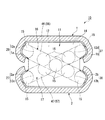
FIG. 10 is a partially transparent perspective view showing an expansion / contraction spline as an expansion / contraction device according to a fourth embodiment of the present invention, FIG. 11 is an exploded perspective view showing a schematic configuration of a movable body of the expansion / contraction spline of the fourth embodiment, and FIG. [FIG. 12] It is a sectional side view which shows the AA arrow of FIG.
図10乃至図12に示すように、本実施形態の伸縮スプライン40は、延在する略丸棒状の軌道体(第1延在部材)41と、この軌道体41に貫通され長手方向に延在するとともに、該軌道体41と長手方向の外形長さが略同一に設定される略円筒状の筒体(第2延在部材)42とを有している。また、軌道体41と筒体42との間には、該筒体42の筒内に収容されるように、略円筒状の移動体51が配設される。すなわち、筒状の移動体51に棒状の軌道体41が挿入され、筒状の筒体42に移動体51が挿入された構成とされている。
As shown in FIGS. 10 to 12, the expansion /
軌道体41の外周面には、長手方向に延びる凹溝状の複数の転動体転走面41aが形成される。また、筒体42の内周面には、長手方向に延びる凹溝状の複数の転動体転走面42aが形成される。
また、図11に示すように、移動体51は、その長手方向の中央部分に略円筒状の本体部52を有しており、またこの本体部52を長手方向の両端側から挟むようにして、略円環状の2つの蓋体53が対向配置される。これら蓋体53は、互いに面対称に形成される。
On the outer peripheral surface of the
Further, as shown in FIG. 11, the moving
移動体51の本体部52の内周面には、長手方向に沿って延びる凹溝状の複数の第1負荷転動体転走面52aが形成されている。これら第1負荷転動体転走面52aは、軌道体41の転動体転走面41aに夫々対向配置されて、夫々の第1負荷転動体転走路81を形成している。複数の第1負荷転動体転走面52aは、移動体51の内周面に互いに周方向等間隔に配置されている。
On the inner peripheral surface of the
また、移動体51の本体部52の外周面には、長手方向に沿って延びる凹溝状の複数の第2負荷転動体転走面52bが形成されている。これら第2負荷転動体転走面52bは、筒体42の転動体転走面42aに夫々対向配置され、夫々の第2負荷転動体転走路82を形成している。複数の第2負荷転動体転走面52bは、移動体51の外周面に互いに周方向等間隔に配置されている。
また、第1負荷転動体転走面52aと第2負荷転動体転走面52bとは、移動体51の周方向に互いに異なる位置に形成され、例えば軌道体41の中心軸を中心に45°程度ずらされるように配置される。
A plurality of second load rolling
Further, the first loaded rolling
また、第1負荷転動体転走面52aと第2負荷転動体転走面52bとを滑らかに繋ぐように、本体部52の長手方向の両端面から突出して複数の転動体方向転換内周案内部52cが形成されている。また、夫々の蓋体53の本体部52を向く面には、転動体方向転換内周案内部52cに対向して配置されるとともに、転動体方向転換内周案内部52cとの間に間隙を開けるように略凹溝状に形成される複数の転動体方向転換外周案内部53aが設けられている。
そして、これら転動体方向転換内周案内部52cと転動体方向転換外周案内部53aとに挟まれるように転動体方向転換路83が複数形成されている。
Moreover, it protrudes from the both end surfaces of the longitudinal direction of the main-
A plurality of rolling element
また、第1負荷転動体転走路81、第2負荷転動体転走路82及び転動体転走路83からなる長丸ループ状の複数の無限循環路90が形成されている。すなわち、長手方向に沿って互いに略平行に配置される第1負荷転動体転走路81と第2負荷転動体転走路82とを、2つの転動体転走路83が長手方向の一方側と他方側とで滑らかに繋ぐように無限循環路90を形成している。
また、移動体51には、これら無限循環路90の路内を充満させるように複数のボール(転動体)55が収納されて保持されており、夫々のボール55が路内を循環して転走可能とされている。
A plurality of
The moving
軌道体41と移動体51とは、第1負荷転動体転走路81にボール55を保持することで、周方向の相対的な移動を規制されており、またボール55の転走により長手方向に相対移動可能とされている。また、筒体42と移動体51とは、第2負荷転動体転走路82にボール55を保持することで、周方向の相対的な移動を規制されており、またボール55の転走により長手方向に相対移動可能とされている。
The
次に、このように構成される伸縮スプライン40の動作について説明する。
予め収縮状態にある伸縮スプライン40が、図10に示すように伸長する際には、軌道体41と筒体42とが長手方向に互いに離間する向きに移動する。この際、移動体51に対し軌道体41が他方側(図10における右側)に相対移動するのにともなって、第1負荷転動体転走路81に配置されるボール55が、該第1負荷転動体転走路81内を他方側へと転走する。
Next, the operation of the
When the
また、移動体51に対し筒体42が一方側(図10における左側)に相対移動するのにともなって、第2負荷転動体転走路82に配置されるボール55が、該第2負荷転動体転走路82内を一方側へと転走する。
Further, as the
また、これら第1、第2負荷転動体転走路81,82に配置される夫々のボール55の長手方向の逆方向への転走にともない、他方側の転動体方向転換路83に配置されるボール55は、第1負荷転動体転走路81の他方側の端部から第2負荷転動体転走路82の他方側の端部へ向け方向転換されるように転走する。また、一方側の転動体方向転換路83に配置されるボール55は、第2負荷転動体転走路82の一方側の端部から第1負荷転動体転走路81の一方側の端部へ向け方向転換されるように転走する。
Further, as the
すなわち、軌道体41、移動体51及び筒体42の長手方向の相対移動により、夫々の無限循環路90に保持される複数のボール55が、ループ状の路内全体に循環するようになっており、これらボール55が循環することによって、伸縮スプライン40は軌道体41と筒体42とを長手方向に滑らかに相対移動させ伸長する。
That is, due to the relative movement in the longitudinal direction of the
また、伸長状態にある伸縮スプライン40が収縮して、軌道体41と筒体42とが互いに長手方向の相対位置を重ねるように近接する際には、無限循環路90の路内の夫々のボール55が、前述の伸長の際のボール55の転走の向きとは逆向きに転走し循環する。そして、これらボール55が循環することによって、伸縮スプライン40は軌道体41と筒体42とを長手方向に滑らかに相対移動させ収縮する。
In addition, when the
以上説明したように、本実施形態の伸縮スプライン40によれば、前述の第1〜第3の実施形態の伸縮ガイド10,20,30において説明した効果と同様の効果を有している。
また、棒状の軌道体41が筒状の移動体51に囲繞され、移動体51が筒状の筒体42に囲繞されて、軌道体41、移動体51及び筒体42が長手方向に相対移動し伸縮運動が行われるので、この伸縮スプライン40を機器等に組み込むことで、種々様々な運動への要望・用途に対応できる。また、この移動体51は筒状に形成されているので、装置に掛かる捻り等のモーメントに対する強度が充分に確保されており、伸縮スプライン40の強度が向上している。
As described above, according to the expansion /
Further, the rod-
第1負荷転動体転走路81、第2負荷転動体転走路82及びこれらを繋ぐ2つの転動体方向転換路83からなるループ状の無限循環路90が形成されるので、従来のように、相対移動の転走に用いられたボール55を再び負荷転動体転走路に戻すために用いられる無負荷循環路は設けられない。従って、ボール55の転走が、その循環する長手方向の往と復とで無駄なく有効に行われる。
Since a loop-shaped
また、第1負荷転動体転走路81、第2負荷転動体転走路82及び転動体方向転換路83からなる無限循環路90が複数組設けられているとともに、これら無限循環路90が移動体51の軌道体41周りに周方向均等に互いに間隔を開け配置されているので、伸縮スプライン40の外周から装置に掛かる外力に対する機械的強度が増し、伸縮運動の精度が十分確保されている。尚、夫々の無限循環路90同士の周方向の配置間隔は、本実施形態の周方向均等に限定されるものではなく、例えば周方向に互いに不均等に間隔を開け配置することとしても構わない。
また、筒体42が略円筒状に形成されているので、装置の長手方向に直交する径方向の外形を小さく設定することができ、省スペース化が可能である。
In addition, a plurality of
Further, since the
次に、本発明の第5の実施形態について説明する。
図13は本発明の第5の実施形態の伸縮装置としての伸縮スプラインを示す部分透過斜視図、図14は第5の実施形態の伸縮スプラインの移動体の概略構成を示す分解斜視図、図15は図14のB−B矢視を示す側断面図である。
尚、前述の第4の実施形態の伸縮スプライン40と同一部材には同一の符号を付し、その説明を省略する。
Next, a fifth embodiment of the present invention will be described.
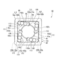
13 is a partially transparent perspective view showing a telescopic spline as a telescopic device according to a fifth embodiment of the present invention, FIG. 14 is an exploded perspective view showing a schematic configuration of a movable body of the telescopic spline of the fifth embodiment, and FIG. [FIG. 15] It is a sectional side view which shows the BB arrow of FIG.
In addition, the same code | symbol is attached | subjected to the same member as the expansion-
図13乃至図15に示すように、本実施形態の伸縮スプライン50は、軌道体41に貫通され長手方向に延在するとともに該軌道体41と長手方向の外形長さが略同一に設定される略角筒状の筒体(第2延在部材)92を有している。また、軌道体41と筒体92との間には、該筒体92の筒内に収容されるように、略角筒状の移動体101が配設される。すなわち、筒状の移動体101に棒状の軌道体41が挿入され、筒状の筒体92に移動体101が挿入された構成とされている。
As shown in FIGS. 13 to 15, the
筒体92の内周の四隅は、長手方向に延びる凹溝状に夫々形成されて転動体転走面92aとされている。
また、図14に示すように、移動体101は、その長手方向の中央部分に略角筒状の本体部102を有しており、本体部102の長手方向に直交する断面中央は、軌道体41が貫通可能な略円柱孔状に形成されている。また、この本体部102を長手方向の両端側から挟むように、略角板状の2つの蓋体103が対向配置されており、これら蓋体103の断面中央は、軌道体41が貫通可能な略円孔状に形成されている。これら蓋体103は、互いに面対称に形成される。
The four corners of the inner periphery of the
Further, as shown in FIG. 14, the moving
移動体101の本体部102の内周面には、長手方向に沿って延びる凹溝状の複数の第1負荷転動体転走面102aが形成されている。これら第1負荷転動体転走面102aは、軌道体41の転動体転走面41aに夫々対向配置されて、夫々の第1負荷転動体転走路111を形成している。複数の第1負荷転動体転走面102aは、移動体101の内周面に互いに周方向等間隔に配置されている。
On the inner peripheral surface of the
また、移動体101の本体部102の外周の四隅には、長手方向に沿って延びる凹溝状の複数の第2負荷転動体転走面102bが形成されている。これら第2負荷転動体転走面102bは、筒体92の転動体転走面92aに夫々対向配置され、夫々の第2負荷転動体転走路112を形成している。
また、第1負荷転動体転走面102aと第2負荷転動体転走面102bとは、移動体101の周方向に互いに異なる位置に形成され、例えば軌道体41の中心軸を中心に45°程度ずらされるように配置される。
In addition, a plurality of concave groove-shaped second load rolling
In addition, the first loaded rolling
また、第1負荷転動体転走面102aと第2負荷転動体転走面102bとを滑らかに繋ぐように、本体部102の長手方向の両端面から突出して複数の転動体方向転換内周案内部102cが形成されている。また、夫々の蓋体103の本体部102を向く面には、転動体方向転換内周案内部102cに対向して配置されるとともに、転動体方向転換内周案内部102cとの間に間隙を開けるように略凹溝状に形成される複数の転動体方向転換外周案内部103aが設けられている。
そして、これら転動体方向転換内周案内部102cと転動体方向転換外周案内部103aとに挟まれるように転動体方向転換路113が複数形成されている。
Also, a plurality of rolling element direction change inner peripheral guides projecting from both longitudinal end surfaces of the
A plurality of rolling element
また、第1負荷転動体転走路111、第2負荷転動体転走路112及び転動体転走路113からなる長丸ループ状の複数の無限循環路120が形成されている。すなわち、長手方向に沿って互いに略平行に配置される第1負荷転動体転走路111と第2負荷転動体転走路112とを、2つの転動体転走路113が長手方向の一方側と他方側とで滑らかに繋ぐように無限循環路120を形成している。
In addition, a plurality of
軌道体41と移動体101とは、第1負荷転動体転走路111にボール55を保持することで、周方向の相対的な移動を規制されており、またボール55の転走により長手方向に相対移動可能とされている。また、筒体92と移動体101とは、第2負荷転動体転走路112にボール55を保持すること及び筒体92の内周と移動体101の外周とが嵌め合わされるように係合していることで、周方向の相対的な移動を規制されており、また、第2負荷転動体転走路112のボール55の転走により、長手方向に相対移動可能とされている。
The
以上説明したように、本実施形態の伸縮スプライン50によれば、前述の第4の実施形態の伸縮スプライン40において説明した効果と同様の効果を有している。
また、筒体92が角筒状に形成され、筒体92の転動体転走面92aを内周の四隅の角部を用いて形成することができるので、転動体転走面92aを形成するために切削加工等を行う工程が削減でき、製作工程が削減可能で生産性が向上する。
As described above, according to the expansion /
Moreover, since the
尚、本発明は前述した第1〜第5の実施形態に限定されるものではなく、本発明の趣旨を逸脱しない範囲において種々の変更を加えることが可能である。
例えば、第1、第2の実施形態では、夫々無限循環路を2つ設けることとして説明したが、これに限らず、無限循環路を1つ或いは3つとして装置を構成してもよく、また4つ以上としても構わない。また、第4、第5の実施形態では、無限循環路を複数組設けることとして説明したが、無限循環路は1つであってもよい。ただし無限循環路を1つとする場合には、移動体と各レールとの間にさらにすべり案内機構を用いるなどして、これら移動体と各レール、軌道体又は筒体とを安定させ確実に係合させることが好ましい。
The present invention is not limited to the first to fifth embodiments described above, and various modifications can be made without departing from the spirit of the present invention.
For example, in the first and second embodiments, it has been described that two infinite circulation paths are provided. However, the present invention is not limited to this, and the apparatus may be configured with one or three infinite circulation paths. Four or more may be used. In the fourth and fifth embodiments, a plurality of infinite circulation paths are provided. However, one infinite circulation path may be provided. However, when there is one infinite circulation path, a sliding guide mechanism is further used between the moving body and each rail so that the moving body and each rail, track body or cylinder are stabilized and securely engaged. It is preferable to combine them.
また、第3の実施形態では、無限循環路80を1条設けることとして説明したが、これに限らず、例えばこの無限循環路80を移動体31の長手方向に隣接するようにして2つ以上並べて装置を構成しても構わない。
In the third embodiment, one
また、第4、第5の実施形態では、軌道体41が略丸棒状に形成されるとして説明したが、これに限らず、例えばその長手方向に直交する断面が略楕円形状、略三角形状、略四角形状又は略六角形状等、それ以外の棒状に形成されることとしてもよい。また、軌道体41を棒状に形成せずに、筒状や板状等それ以外の形状としても構わない。
また、第4、第5の実施形態では、移動体51,101及び筒体42,92が夫々略円筒状又は略角筒状に形成されることとして説明したが、これらの形状に限定されるものではなく、略楕円筒状、略三角筒状又は略六角筒状等それ以外の形状であっても構わない。また、移動体51,101及び筒体42,92を筒状に形成せずに、例えば周方向の一部を切り欠いて断面略C字状に形成する等、それ以外の形状としても構わない。
In the fourth and fifth embodiments, the
In the fourth and fifth embodiments, the
また、第1〜第5の実施形態では、転動体としてボール15,55を備えるものとして説明したが、これに限らず、例えばボール15,55の代わりに略円柱状のコロを用いて装置を構成しても構わない。
In the first to fifth embodiments, the
1…第1レール(第1延在部材)、 1a,1b,2a,2b,41a,42a,92a…転動体転走面、 2…第2レール(第2延在部材)、 10,20,30…伸縮ガイド(伸縮装置)、 11,21,31,51,101…移動体、 12a,12d,22a,22c,52a,102a…第1負荷転動体転走面、 12b,12c,22b,22d,52b,102b…第2負荷転動体転走面、 15,55…ボール(転動体)、 26,37,61,71,81,111…第1負荷転動体転走路、 27,36,62,72,82,112…第2負荷転動体転走路、 40,50…伸縮スプライン(伸縮装置)、 41…軌道体(第1延在部材)、 42,92…筒体(第2延在部材)、 46,47,56,57,63,73,83,113…転動体方向転換路。 DESCRIPTION OF SYMBOLS 1 ... 1st rail (1st extending member), 1a, 1b, 2a, 2b, 41a, 42a, 92a ... Rolling-element rolling surface, 2 ... 2nd rail (2nd extending member), 10, 20, 30 ... telescopic guide (extension device), 11, 21, 31, 51, 101 ... moving body, 12a, 12d, 22a, 22c, 52a, 102a ... first load rolling element rolling surface, 12b, 12c, 22b, 22d , 52b, 102b ... second load rolling element rolling surface, 15, 55 ... ball (rolling element), 26, 37, 61, 71, 81, 111 ... first load rolling element rolling path, 27, 36, 62, 72, 82, 112 ... second load rolling element rolling path, 40, 50 ... telescopic spline (extensible device), 41 ... raceway (first extending member), 42, 92 ... cylindrical body (second extending member) 46, 47, 56, 57, 63, 73, 83, 13 ... rolling element direction changing passage.
Claims (7)
この第1延在部材と同一方向に延在する第2延在部材と、
これら第1延在部材及び第2延在部材の間に配設され前記延在する長手方向に相対移動させる移動体と、
前記第1延在部材及び前記第2延在部材と前記移動体との間に配置される複数の転動体と、
前記移動体の第1負荷転動体転走面と前記第1延在部材の転動体転走面とにより形成される第1負荷転動体転走路と、
前記移動体の第2負荷転動体転走面と前記第2延在部材の転動体転走面とにより形成される第2負荷転動体転走路と、
前記移動体の両端に形成され前記第1、第2負荷転動体転走路を繋ぐ転動体方向転換路と、を有することを特徴とする伸縮装置。 A first extending member;
A second extending member extending in the same direction as the first extending member;
A movable body disposed between the first extending member and the second extending member and relatively moving in the extending longitudinal direction;
A plurality of rolling elements disposed between the first extending member and the second extending member and the moving body;
A first load rolling element rolling path formed by the first load rolling element rolling surface of the moving body and the rolling element rolling surface of the first extending member;
A second load rolling element rolling path formed by the second load rolling element rolling surface of the movable body and the rolling element rolling surface of the second extending member;
A telescopic device comprising: a rolling element direction changing path formed at both ends of the moving body and connecting the first and second load rolling element rolling paths.
前記移動体には、前記第1、第2負荷転動体転走路及び前記転動体方向転換路が夫々2組設けられており、
少なくとも一方側の前記転動体方向転換路が、前記長手方向から見て互いに交差するようにして配置されていることを特徴とする伸縮装置。 The telescopic device according to claim 1,
The moving body is provided with two sets of the first and second load rolling element rolling paths and the rolling element direction changing path, respectively.
A telescopic device, wherein the rolling element direction changing paths on at least one side are arranged so as to intersect each other when viewed from the longitudinal direction.
前記移動体には、前記第1、第2負荷転動体転走路及び前記転動体方向転換路が夫々2組設けられており、
少なくとも一方側の前記転動体方向転換路が、前記長手方向から見て互いに交差しないようにして配置されていることを特徴とする伸縮装置。 The telescopic device according to claim 1,
The moving body is provided with two sets of the first and second load rolling element rolling paths and the rolling element direction changing path, respectively.
The telescopic device, wherein the rolling element direction changing paths on at least one side are arranged so as not to cross each other when viewed from the longitudinal direction.
一方側の前記転動体方向転換路が、前記長手方向から見て互いに交差するようにして配置されているとともに、他方側の前記転動体方向転換路が、前記長手方向から見て互いに交差しないようにして配置されていることを特徴とする伸縮装置。 The telescopic device according to claim 2 or 3,
The rolling element direction changing paths on one side are arranged so as to intersect with each other when viewed from the longitudinal direction, and the rolling element direction changing paths on the other side do not intersect with each other when viewed from the longitudinal direction. A telescopic device characterized by being arranged as described above.
前記移動体を前記長手方向に貫通して延びる軸体が配設されており、
前記軸体が、前記移動体と前記長手方向に相対移動可能とされていることを特徴とする伸縮装置。 The telescopic device according to claim 3,
A shaft extending through the moving body in the longitudinal direction is disposed;
The telescopic device, wherein the shaft body is movable relative to the moving body in the longitudinal direction.
前記第1延在部材が、前記移動体を前記長手方向に貫通し、
前記移動体が、前記長手方向に直交する向きの周囲を前記第2延在部材に囲繞されることを特徴とする伸縮装置。 The telescopic device according to claim 1,
The first extending member penetrates the moving body in the longitudinal direction;
A telescopic device, wherein the movable body is surrounded by the second extending member in a direction perpendicular to the longitudinal direction.
前記第1負荷転動体転走路、前記第2負荷転動体転走路及び前記転動体方向転換路からなる無限循環路が複数組設けられるとともに、夫々の前記無限循環路が、前記移動体の前記第1延在部材周りに周方向に互いに間隔を開け配置されることを特徴とする伸縮装置。 The telescopic device according to claim 6,
A plurality of infinite circulation paths each including the first load rolling element rolling path, the second load rolling element rolling path, and the rolling element direction changing path are provided, and each of the infinite circulation paths is the first of the moving body. A telescopic device characterized in that it is disposed around the extending member in the circumferential direction with a space therebetween.
Priority Applications (1)
| Application Number | Priority Date | Filing Date | Title |
|---|---|---|---|
| JP2008143716A JP2009144902A (en) | 2007-11-21 | 2008-05-30 | Expansion device |
Applications Claiming Priority (2)
| Application Number | Priority Date | Filing Date | Title |
|---|---|---|---|
| JP2007302092 | 2007-11-21 | ||
| JP2008143716A JP2009144902A (en) | 2007-11-21 | 2008-05-30 | Expansion device |
Publications (1)
| Publication Number | Publication Date |
|---|---|
| JP2009144902A true JP2009144902A (en) | 2009-07-02 |
Family
ID=40915715
Family Applications (1)
| Application Number | Title | Priority Date | Filing Date |
|---|---|---|---|
| JP2008143716A Withdrawn JP2009144902A (en) | 2007-11-21 | 2008-05-30 | Expansion device |
Country Status (1)
| Country | Link |
|---|---|
| JP (1) | JP2009144902A (en) |
Cited By (3)
| Publication number | Priority date | Publication date | Assignee | Title |
|---|---|---|---|---|
| WO2017163867A1 (en) * | 2016-03-22 | 2017-09-28 | アイシン精機 株式会社 | Vehicular slide device, and rolling element circulation unit |
| EP3859176A1 (en) * | 2020-02-03 | 2021-08-04 | Liebherr-Verzahntechnik GmbH | Telescopic rail |
| CN116292616A (en) * | 2022-11-23 | 2023-06-23 | 柯拉思利工业科技(上海)有限公司 | A light-weight, long-life and high-load circulating roller bearing |
-
2008
- 2008-05-30 JP JP2008143716A patent/JP2009144902A/en not_active Withdrawn
Cited By (4)
| Publication number | Priority date | Publication date | Assignee | Title |
|---|---|---|---|---|
| WO2017163867A1 (en) * | 2016-03-22 | 2017-09-28 | アイシン精機 株式会社 | Vehicular slide device, and rolling element circulation unit |
| EP3859176A1 (en) * | 2020-02-03 | 2021-08-04 | Liebherr-Verzahntechnik GmbH | Telescopic rail |
| DE102020102644A1 (en) | 2020-02-03 | 2021-08-05 | Liebherr-Verzahntechnik Gmbh | Telescopic rail |
| CN116292616A (en) * | 2022-11-23 | 2023-06-23 | 柯拉思利工业科技(上海)有限公司 | A light-weight, long-life and high-load circulating roller bearing |
Similar Documents
| Publication | Publication Date | Title |
|---|---|---|
| CN103492758B (en) | Linear movement guide mechanism | |
| JP6092976B1 (en) | Actuator | |
| US8757024B2 (en) | Linear motion assembly with recirculation insert | |
| TWI651477B (en) | Motion guiding device | |
| JP5767561B2 (en) | Linear motion guidance unit | |
| JP6626162B2 (en) | Motorless actuator, actuator, and method of manufacturing motorless actuator | |
| JP5686910B2 (en) | Exercise guidance device | |
| JP2009144902A (en) | Expansion device | |
| US5228783A (en) | Stability enhanced linear motion guide unit | |
| JP2015206456A (en) | Rolling device | |
| JP4493103B2 (en) | Exercise guidance device | |
| JP2014149062A (en) | Motion guide device | |
| JP3214017U (en) | Roller spline assembly | |
| JP5169803B2 (en) | Linear motion guide device | |
| CN111065831B (en) | motion guide | |
| JP2011117593A (en) | Limited stroke motion guide apparatus | |
| EP1653097A1 (en) | Linear guide device with offset-load prevention mechanism | |
| JPS6037465Y2 (en) | Guide device for linear motion | |
| JP2008089004A (en) | Rolling guide device | |
| JP5425562B2 (en) | Rolling element screw device | |
| JP2013050148A (en) | Ball screw | |
| JP7079173B2 (en) | Exercise guidance device | |
| JP2008240882A (en) | Linear guide device | |
| JP2006077796A5 (en) | ||
| JP2016217484A (en) | Rolling bearing guide device |
Legal Events
| Date | Code | Title | Description |
|---|---|---|---|
| A300 | Withdrawal of application because of no request for examination |
Free format text: JAPANESE INTERMEDIATE CODE: A300 Effective date: 20110802 |