JP2009166830A - Electronic apparatus for bicycle - Google Patents
Electronic apparatus for bicycle Download PDFInfo
- Publication number
- JP2009166830A JP2009166830A JP2008323497A JP2008323497A JP2009166830A JP 2009166830 A JP2009166830 A JP 2009166830A JP 2008323497 A JP2008323497 A JP 2008323497A JP 2008323497 A JP2008323497 A JP 2008323497A JP 2009166830 A JP2009166830 A JP 2009166830A
- Authority
- JP
- Japan
- Prior art keywords
- electronic device
- bicycle electronic
- controller
- bicycle
- connector
- Prior art date
- Legal status (The legal status is an assumption and is not a legal conclusion. Google has not performed a legal analysis and makes no representation as to the accuracy of the status listed.)
- Pending
Links
- 230000015654 memory Effects 0.000 claims abstract description 62
- 238000012546 transfer Methods 0.000 claims abstract description 13
- 230000006854 communication Effects 0.000 claims description 78
- 238000004891 communication Methods 0.000 claims description 77
- 238000009413 insulation Methods 0.000 claims description 14
- 238000000034 method Methods 0.000 claims description 4
- 230000005540 biological transmission Effects 0.000 description 38
- 238000002955 isolation Methods 0.000 description 6
- 230000004044 response Effects 0.000 description 6
- 238000010586 diagram Methods 0.000 description 4
- 238000012217 deletion Methods 0.000 description 3
- 230000037430 deletion Effects 0.000 description 3
- 238000012790 confirmation Methods 0.000 description 2
- ATJFFYVFTNAWJD-UHFFFAOYSA-N Tin Chemical compound [Sn] ATJFFYVFTNAWJD-UHFFFAOYSA-N 0.000 description 1
- 230000002457 bidirectional effect Effects 0.000 description 1
- 230000015572 biosynthetic process Effects 0.000 description 1
- 230000001934 delay Effects 0.000 description 1
- 238000001514 detection method Methods 0.000 description 1
- 238000003745 diagnosis Methods 0.000 description 1
- 239000012777 electrically insulating material Substances 0.000 description 1
- 238000005516 engineering process Methods 0.000 description 1
- 238000011156 evaluation Methods 0.000 description 1
- 230000006870 function Effects 0.000 description 1
- 238000012986 modification Methods 0.000 description 1
- 230000004048 modification Effects 0.000 description 1
- 230000000737 periodic effect Effects 0.000 description 1
- 230000002093 peripheral effect Effects 0.000 description 1
- 230000008569 process Effects 0.000 description 1
- 230000001360 synchronised effect Effects 0.000 description 1
- 238000012549 training Methods 0.000 description 1
- 238000011144 upstream manufacturing Methods 0.000 description 1
Images

Classifications
-
- B—PERFORMING OPERATIONS; TRANSPORTING
- B62—LAND VEHICLES FOR TRAVELLING OTHERWISE THAN ON RAILS
- B62M—RIDER PROPULSION OF WHEELED VEHICLES OR SLEDGES; POWERED PROPULSION OF SLEDGES OR SINGLE-TRACK CYCLES; TRANSMISSIONS SPECIALLY ADAPTED FOR SUCH VEHICLES
- B62M25/00—Actuators for gearing speed-change mechanisms specially adapted for cycles
- B62M25/08—Actuators for gearing speed-change mechanisms specially adapted for cycles with electrical or fluid transmitting systems
-
- A—HUMAN NECESSITIES
- A63—SPORTS; GAMES; AMUSEMENTS
- A63B—APPARATUS FOR PHYSICAL TRAINING, GYMNASTICS, SWIMMING, CLIMBING, OR FENCING; BALL GAMES; TRAINING EQUIPMENT
- A63B24/00—Electric or electronic controls for exercising apparatus of preceding groups; Controlling or monitoring of exercises, sportive games, training or athletic performances
Landscapes
- Engineering & Computer Science (AREA)
- General Health & Medical Sciences (AREA)
- Combustion & Propulsion (AREA)
- Transportation (AREA)
- Mechanical Engineering (AREA)
- Health & Medical Sciences (AREA)
- Chemical & Material Sciences (AREA)
- Physical Education & Sports Medicine (AREA)
- Information Transfer Systems (AREA)
- Traffic Control Systems (AREA)
- Arrangements For Transmission Of Measured Signals (AREA)
- Small-Scale Networks (AREA)
- Automatic Cycles, And Cycles In General (AREA)
- Steering Devices For Bicycles And Motorcycles (AREA)
Abstract
Description
本発明は、自転車用電子装置に関する。 The present invention relates to a bicycle electronic device.
自転車用電子装置は公知であり、自転車に搭載されることができる様々な電子装置および/または電気機械装置を備え得る。 Bicycle electronic devices are well known and may comprise various electronic and / or electromechanical devices that can be mounted on a bicycle.
サイクルコンピュータと称される簡単な自転車用電子装置の場合、適切なセンサによって検出されて場合によっては適切に処理されている、走行時間、走行した距離、現在、平均および最大の速度、現在チェーンによって係合されている歯付きクラウンもしくはスプロケット、または変速比など、様々な走行パラメータすなわち走行データを運転者に表示するために、表示ユニットがハンドルバーに取り付けられていることがある。運転者は、通常、興味のあるデータを走行中に選択してディスプレイに読み出すことができる。さらに、典型的に、上記のようないくつかの走行データの1つ以上の数値、例えば、合計値または最小値および最大値が、後の参照のために(自転車を停止させて行う場合もある)サイクルコンピュータの不揮発性メモリに記憶されている。 In the case of a simple bicycle electronic device called a cycle computer, it is detected by a suitable sensor and possibly properly processed, depending on the travel time, distance traveled, current, average and maximum speed, current chain A display unit may be attached to the handlebar to display various driving parameters or driving data to the driver, such as a toothed crown or sprocket engaged, or a gear ratio. The driver can usually select the data of interest while driving and read it on the display. In addition, typically one or more values of some of the driving data as described above, for example total or minimum and maximum values, may be done with the bicycle stopped (for later reference). ) Stored in the non-volatile memory of the cycle computer.
ハンドルバーに固定された支持体に表示ユニットが取外し可能に取り付けられている場合、運転者は、自転車から離れても所望どおりに走行データを参照することができる。 When the display unit is detachably attached to the support body fixed to the handlebar, the driver can refer to the traveling data as desired even after leaving the bicycle.
公知の取外し可能なサイクルコンピュータには、コンピュータのようなデータ受信局へのデータの送信のために接続を可能にするものもあり、データは、自身の運転実績(パフォーマンス)を評価するために運転者によって読み出されることができる。適切なソフトウェアプログラムの使用により、解釈しやすくなるように、および/またはコンピュータに表示されるように、このようなデータの処理が可能になる。 Some known removable cycle computers allow connection for transmission of data to a data receiving station such as a computer, where the data is run to evaluate its own performance. Can be read by a person. The use of appropriate software programs allows such data to be processed for ease of interpretation and / or display on a computer.
公知のサイクルコンピュータの場合、コンピュータとの接続には、赤外線伝送または超音波伝送が用いられたり、さらには磁気伝達が用いられたりもする。この目的のため、いったん自転車から取り外された表示ユニットが、コンピュータのデータ受信周辺装置に近いコンピュータの近傍に配置される。いったんコンピュータが表示ユニットの存在を検知すると、公知のプロトコルに従いデータ転送が開始できる。 In the case of a known cycle computer, infrared transmission or ultrasonic transmission is used for connection with the computer, and magnetic transmission is also used. For this purpose, the display unit once removed from the bicycle is placed in the vicinity of the computer close to the computer's data receiving peripheral. Once the computer detects the presence of the display unit, data transfer can begin according to a known protocol.
例えば、本願と同一の出願人の特許文献1に記載された、より複雑な自転車用電子装置は、ハンドルバーに接続された制御装置に設けられる適切なスイッチによって制御される電気機械式(前側および後側)のディレイラも備えている。代替案として、またはこれに加えて、ディレイラは、走行状態の論理評価に基づいて、当該自転車用電子装置によって自動的に制御されることができるものであってもよい。 For example, a more complex bicycle electronic device described in the same Applicant's US Pat. No. 6,057,017 is applied to an electromechanical (front and rear) controlled by a suitable switch provided on a control device connected to the handlebar. It also has a rear derailleur. As an alternative or in addition, the derailleur may be one that can be automatically controlled by the bicycle electronic device based on a logical evaluation of the driving conditions.
自転車のギアシフトの管理用でもある上記のような自転車用電子装置の場合、上述したサイクルコンピュータと類似する表示ユニットが設けられ、上述した走行データと、電源バッテリーの状態のようなこの自転車用電子装置の状態に関するデータとを選択および参照することができ、また、この自転車用電子装置の様々なパラメータの調整、例えば、歯車の係合に対応するディレイラの論理的位置の調整も実行されることができる。さらにこの場合、運転者は、走行データ、装置の状態データおよび診断データを、走行時および停止時の両方において参照することができ、取外し可能な表示ユニットの場合、さらには自転車から離れても参照することができる。 In the case of the bicycle electronic device as described above, which is also used for managing the gear shift of the bicycle, a display unit similar to the cycle computer described above is provided, and the bicycle electronic device such as the above-described traveling data and the state of the power battery is provided. Data on the state of the vehicle can be selected and referenced, and adjustments of various parameters of the bicycle electronic device can be performed, for example, adjustment of the logical position of the derailleur corresponding to the engagement of the gears. it can. Furthermore, in this case, the driver can refer to the traveling data, the device status data and the diagnostic data both when traveling and when the vehicle is stopped. can do.
本願の第一出願の日に未だ公開されていなかった、本願と同一の出願人による伊国特許出願の特許文献2に記載された自転車用電子装置では、この自転車用電子装置を構成する様々なユニットが、例えば半二重非同期シリアル通信のような適切な通信プロトコルに従いデータが交換される通信チャネルによって互いに適切に接続されている。 The bicycle electronic device described in Patent Document 2 of the Italian patent application filed by the same applicant as the present application, which has not yet been published on the date of the first application of the present application, includes various types of electronic devices for the bicycle. The units are suitably connected to each other by a communication channel in which data is exchanged according to a suitable communication protocol, for example half-duplex asynchronous serial communication.
公知の自転車用電子装置の欠点は、データ送信のためにはコンピュータの存在が不可欠な点にある。即座にデータを転送する必要がある場合、例えば、表示ユニットのメモリがフルの場合、データのダウンロードは運転者が帰宅するまで、とにかく待たなければならず、フル状態のメモリが原因で新しい取得を損なうか、または新しいデータの記憶を可能にするために最も古いデータを削除しなければならない。 A disadvantage of known bicycle electronic devices is that the presence of a computer is essential for data transmission. If the data needs to be transferred immediately, for example if the display unit memory is full, the data download has to wait anyway until the driver returns home, and the full memory will cause a new acquisition. The oldest data must be deleted in order to damage or allow storage of new data.
公知の自転車用電子装置の他の欠点は、表示ユニットからコンピュータへの送信が遅くなり得る点にある。 Another disadvantage of the known bicycle electronic device is that transmission from the display unit to the computer can be slow.
さらなる欠点は、表示ユニットからコンピュータへの送信が、送信中のデータの損失により、またはこのようなデータを回復するための送信動作を繰り返す必要性により(これによって送信がさらに遅れる)、確実でないことがあり得る点にある。 A further disadvantage is that the transmission from the display unit to the computer is not assured due to the loss of data during transmission or the need to repeat the transmission operation to recover such data (which further delays the transmission) There is a possible point.
公知の自転車用電子装置の他の欠点は、表示ユニットが自転車から取り外されてコンピュータが存在する場所でデータ送信が行わなければならないため、自転車が停止した状態でのみ表示ユニットからコンピュータへの送信を行うことができる点にある。 Another drawback of the known bicycle electronic device is that the display unit must be removed from the bicycle and data must be transmitted where the computer is located, so transmission from the display unit to the computer is only possible when the bicycle is stopped. There is a point that can be done.
本発明の基礎をなす技術的課題は、場合により走行中においても、速くて確実なデータ送信を可能にする自転車用電子装置を提供することである。 The technical problem underlying the present invention is to provide an electronic device for bicycles that allows fast and reliable data transmission, even when traveling.
本発明は、少なくとも1つの不揮発性データメモリを備えた自転車用電子装置に関し、取外し自在な大容量記憶装置用のポートを備えていることを特徴とする。 The present invention relates to a bicycle electronic device having at least one non-volatile data memory, and is characterized by having a port for a removable mass storage device.
取外し自在な大容量記憶装置用のポートを設けることにより、運転者は、表示ユニットを取り外す必要なく不揮発性データメモリからこのような取外し自在な大容量記憶装置へのデータ転送および取外し自在な大容量記憶装置から不揮発性データメモリへのデータ転送をいつでも、さらには走行中でも容易に行うことができる。さらに、物理的接続を利用することにより、データ転送は速く確実である。 By providing a port for a removable mass storage device, the driver can transfer data from the non-volatile data memory to such a removable mass storage device and remove the large capacity without having to remove the display unit. Data transfer from the storage device to the non-volatile data memory can be easily performed at any time and even while traveling. Furthermore, data transfer is fast and reliable by utilizing physical connections.
好ましくは、上記ポートはフラッシュメモリ用のポートである。 Preferably, the port is a flash memory port.
より好ましくは、上記ポートはUSBポートである。 More preferably, the port is a USB port.
有利なことに、このようなUSBポートは、携帯性に極めて優れた装置であるUSBメモリキー用に使用される上に、コンピュータおよび充電器の接続用に使用されることができる。さらに、マウス、キーボード、ハードディスク大容量記憶装置、画像読取装置、デジタルカメラ、プリンタ、スピーカシステム、マイクロフォンおよびその他の接続のために使用されることができる。 Advantageously, such a USB port can be used for connecting a computer and a charger in addition to being used for a USB memory key, which is a highly portable device. In addition, it can be used for mouse, keyboard, hard disk mass storage, image reading device, digital camera, printer, speaker system, microphone and other connections.
代替案として、上記ポートは、MiniSDもしくはMicroSD、CompactFlash、SmartMedia(登録商標)、MultiMediaCard、Memory Stick、Secure Digital、およびxD−Picture memoryなど、メモリカード用のポートである。 Alternatively, the port is a memory card port such as MiniSD or MicroSD, CompactFlash, SmartMedia (registered trademark), MultiMediaCard, Memory Stick, Secure Digital, and xD-Picture memory.
好ましくは、さらに、自転車用電子装置は、上記少なくとも1つの不揮発性データメモリにアクセスする少なくとも1つのコントローラと、当該少なくとも1つのコントローラと上記ポートとの間のデータ転送を管理するさらなるコントローラとを備えている。 Preferably, the bicycle electronic device further comprises at least one controller for accessing the at least one non-volatile data memory, and a further controller for managing data transfer between the at least one controller and the port. ing.
好ましくは、上記少なくとも1つの不揮発性データメモリと上記取外し自在な大容量記憶装置との間で交換されるデータの一時的記憶のために、バッファメモリが上記さらなるコントローラに組み合わされている。 Preferably, a buffer memory is associated with the further controller for temporary storage of data exchanged between the at least one non-volatile data memory and the removable mass storage device.
より好ましくは、上記少なくとも1つのコントローラと上記さらなるコントローラとは、半二重非同期シリアル通信プロトコルによって通信を行う。 More preferably, the at least one controller and the further controller communicate via a half-duplex asynchronous serial communication protocol.
さらに好ましくは、上記少なくとも1つのコントローラと上記さらなるコントローラとは、2つの信号線を備えた通信チャネルを通して通信を行う。 More preferably, the at least one controller and the further controller communicate through a communication channel having two signal lines.
代替案として、この通信は無線(ワイヤレス)であってもよい。 As an alternative, this communication may be wireless.
好ましくは、さらに、上記ポートは、有利なことに低電力装置に電力供給するために利用されることができる電力供給端子を有するコネクタを備えている。 Preferably, the port further comprises a connector having a power supply terminal that can be advantageously used to power a low power device.
好ましくは、さらに、上記さらなるコントローラと上記ポートとは、上記自転車用電子装置に着脱自在に接続可能なインタフェースユニットの一部である。 Preferably, the further controller and the port are part of an interface unit that is detachably connectable to the bicycle electronic device.
このようにして、運転者は、データ転送が必要でないと確信すれば、インタフェースユニットを取り外し、自転車を軽量化することを決めることができる。 In this way, if the driver is convinced that no data transfer is necessary, he can decide to remove the interface unit and reduce the weight of the bicycle.
好ましくは、このインタフェースユニットは、さらに、その構成品および/またはコネクタ用の電力供給装置を備えている。 Preferably, the interface unit further comprises a power supply device for its components and / or connectors.
セルフパワーのインタフェースユニットを設けることにより、自転車用電子装置のインタフェースユニット以外の部分における着脱自在なコネクタに電圧が印加された状態の端子が存在することを避けられる。 By providing the self-powered interface unit, it is possible to avoid the presence of a terminal in which a voltage is applied to a detachable connector in a portion other than the interface unit of the bicycle electronic device.
好ましくは、上記電力供給装置は、必要なときにのみインタフェースユニットが電力供給されることを可能にするオン/オフスイッチを備えている。 Preferably, the power supply device comprises an on / off switch that allows the interface unit to be powered only when needed.
このオン/オフスイッチは、手動で作動されてもよいし、インタフェースユニットが接続されたときに自動的に接続される、例えば、磁気的に作動されるスイッチであってもよい。 The on / off switch may be manually operated or may be automatically connected when the interface unit is connected, for example, a magnetically operated switch.
より好ましくは、上記インタフェースユニットは、対応するコネクタと着脱自在に結合可能なさらなるコネクタを備えており、当該対応するコネクタが、このインタフェースユニットの上記電力供給装置によって駆動可能な絶縁装置を介して、上記自転車用電子装置の通信チャネルに接続されている。 More preferably, the interface unit includes a further connector that can be detachably coupled to a corresponding connector, and the corresponding connector is connected via an insulating device that can be driven by the power supply device of the interface unit. It is connected to the communication channel of the bicycle electronic device.
好ましくは、上記絶縁装置は、上記通信チャネルの通信線の数に等しい個数の絶縁スイッチを備えている。 Preferably, the insulation device includes a number of insulation switches equal to the number of communication lines of the communication channel.
好ましくは、これら絶縁スイッチはMOSFETで構成されるが、例えば、トランジスタまたは継電器で構成されてもよい。これら絶縁スイッチは、インタフェースユニットが接続されたときに自動的に作動されるスイッチであってもよく、例えば、磁気的に作動されるスイッチである。 Preferably, these isolation switches are composed of MOSFETs, but may be composed of transistors or relays, for example. These isolation switches may be switches that are automatically activated when the interface unit is connected, for example magnetically activated switches.
さらに好ましくは、上記対応するコネクタは、上記自転車用電子装置の表示ユニットを含むケーシングに設けられているか、または収容されている。 More preferably, the corresponding connector is provided in or accommodated in a casing including the display unit of the bicycle electronic device.
代替案として、上記対応するコネクタは、上記自転車用電子装置のギアシフトの駆動ユニットを含むケーシングに設けられているか、または収容されている。 As an alternative, the corresponding connector is provided or accommodated in a casing containing a gearshift drive unit of the bicycle electronic device.
本発明は、第2の構成において、USBポートを備えた自転車用電子装置に関する。 The present invention relates to a bicycle electronic device having a USB port in a second configuration.
好ましくは、さらに、この自転車用電子装置は、少なくとも1つのコントローラと、当該少なくとも1つのコントローラと上記USBポートとの間の通信を管理するさらなるコントローラとを備えている。 Preferably, the bicycle electronic device further comprises at least one controller and a further controller for managing communication between the at least one controller and the USB port.
本発明のさらなる特徴および利点は、添付された図面を参照して、好ましい実施形態の説明からより明らかになる。 Further features and advantages of the present invention will become more apparent from the description of preferred embodiments with reference to the accompanying drawings.
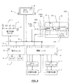
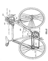
図1において、本発明の第1の実施形態による自転車用電子装置1は、電子制御ユニット2と、ペダルクランクの軸と組み合わされた歯車および/または自転車の後輪のハブと組み合わされた複数の歯車の間で伝動チェーンを移動させるためのチェーンガイド要素またはディレイラに接続された少なくとも1つのアクチュエータ3と、このアクチュエータ3に用いられる駆動ユニット4とを備えている。
In FIG. 1, a bicycle electronic device 1 according to a first embodiment of the present invention comprises an electronic control unit 2, a plurality of gears combined with a pedal crankshaft and / or a bicycle rear wheel hub. At least one
好ましくは、自転車用電子装置1は、さらに、アクチュエータ3の位置つまり間接的にディレイラの位置を検出する、またはディレイラの位置を直接検出するのに適した、ディレイラの移動の際に駆動ユニット4および/またはアクチュエータ3と協働する少なくとも1つの位置検出器5を備えている。
Preferably, the bicycle electronic device 1 further includes a
自転車用電子装置1において、運転者によってレバーまたはボタン(図10における符号401)を介して作動される、手動ギアシフトのリクエストを入力するためのノルマルオープン型の複数のスイッチ6、ならびに/または走行速度、クランクの回転速度、地形の傾きおよび運転者の心拍数などの走行パラメータの1つ以上のセンサ7が、電子制御ユニット2に組み合わされている。センサ7が設けられる場合、これらセンサ7は、当該センサの出力を前処理することができる第2の電子制御ユニット11の制御下にあるのが好ましい。
In the bicycle electronic device 1, a plurality of normally open type switches 6 for inputting a request for manual gear shift, which are operated by a driver via a lever or a button (
自転車用電子装置1は、さらに、運転者に情報を提供する表示ユニット8を備えており、好ましくは、表示されるデータの種類を選択する、ならびに/または他のパラメータおよび/または指令を入力するために、運転者によってボタンまたは多方向スイッチ(ジョイスティック)を介して作動されるさらなるスイッチ9がこの表示ユニット8に組み合わされている。好ましくは、グラフィカルユーザインタフェースの方法で表示ユニット8の表示の各箇所を選択することにより、表示されるデータの種類を選択する、ならびに/または他のパラメータおよび/または指令を入力する。 The bicycle electronic device 1 further comprises a display unit 8 for providing information to the driver, preferably selecting the type of data to be displayed and / or inputting other parameters and / or commands. For this purpose, a further switch 9 which is actuated by the driver via a button or a multidirectional switch (joystick) is associated with this display unit 8. Preferably, the type of data to be displayed is selected and / or other parameters and / or commands are entered by selecting each location of display on the display unit 8 in a graphical user interface manner.
好ましくは、電子制御ユニット2は、運転者によって作動されることができる制御部材(図10における符号402)の近傍、すなわちハンドルバーの近傍に配置されており、詳細には、ハンドルバーの中心部に固定された表示ユニット8のケーシング(図10における符号403)に収納されることができる。
Preferably, the electronic control unit 2 is arranged in the vicinity of a control member (
好ましくは、駆動ユニット4は、アクチュエータ3(図10では符号404,405)の近傍、例えば、自転車のボトルホルダ(図10における符号406)の近傍に配置されている。
Preferably, the
電子制御ユニット2、表示ユニット8、駆動ユニット4、および第2の電子制御ユニットすなわちセンサユニット11は、通信チャネル10を介して適切な通信プロトコルによって通信を行う。
The electronic control unit 2, the display unit 8, the
好ましくは、上記通信はケーブルを介したものであるが、代替案として無線(ワイヤレス)であってもよい。 Preferably, the communication is via a cable, but may alternatively be wireless.
図1は、さらに、自転車用電子装置1の構成品の電力供給線12を概略的に示している(電源については示されていない)。自転車用電子装置1は、典型的に充電池の形態である1つ以上の電源を備えていてもよく、好ましくは、電子制御ユニット2を含むケーシングに配置された第1の電源と、表示ユニット8を含む、または表示ユニット8を着脱自在に支持するケーシング(図10における符号403)に配置された第2の電源とを備えている。
FIG. 1 further schematically shows a
本発明による自転車用電子装置1は、さらに、着脱自在なインタフェースユニット50を備えている。
The bicycle electronic device 1 according to the present invention further includes a
インタフェースユニット50は、その第1のコネクタCN1を介して対応するコネクタCN1’に接続されることができ、このコネクタCN1’は自転車用電子装置1のコネクタCN1’以外の部分と組み合わされている。具体的には、このコネクタCN1’は、通信チャネル10の適切な物理的ポイント、例えば、表示ユニット8の近傍、つまりハンドルバーの近傍(図10におけるケーシング403に設けられているか、または収容されているコネクタCN1’もしくは図10における左側の制御部材402に示されたコネクタCN1’など)、または駆動ユニット4の近傍(図10における後側のディレイラ404の近傍もしくは図10における前側のディレイラ405の近傍に示されたコネクタCN1’など)、特に、ボトルホルダ部分(図10におけるボトルホルダ406に示されたコネクタCN1’など)で、自転車用電子装置1のコネクタCN1’以外の部分と組み合わされている。コネクタCN1’は、駆動ユニット4を含むケーシングに設けられてもよい。
The
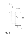
通信チャネル10とコネクタCN1’との間には、駆動可能な絶縁装置51が設けられている。図2で詳細に示される駆動可能な絶縁装置51は、通信チャネル10の通信線の数に等しい個数(図示の場合では2つ)の絶縁スイッチ51a,51bを備えており、この絶縁スイッチは、接続されると、インタフェースユニット50から配線52に沿って受信される制御信号によって駆動されることができる。
A
絶縁装置51の絶縁スイッチ51a,51bはノルマルオープン型であるため、インタフェースユニット50が接続されていないときのコネクタCN1’の端子の電気絶縁を可能にする。好ましくは、絶縁スイッチ51a,51bはMOSFETで構成されるが、例えば、トランジスタまたは継電器で構成されてもよい。絶縁スイッチ51a,51bは、インタフェースユニット50がコネクタCN1’に接続されたときに自動的に作動されるスイッチであってもよく、例えば、コネクタCN1における1つ以上の磁石に反応する磁気的に作動されるスイッチである。
Since the insulation switches 51a and 51b of the
インタフェースユニット50は、通信チャネル10への接続用のコネクタCN1に加えて、USBインタフェースが備えられた電子装置である取外し自在な大容量記憶装置99、例えば、USBメモリキー99への接続のために、トランシーバ54およびコネクタCN2を有するUSBポートを備えている。インタフェースユニット50は、さらに、USBポート54、CN2と通信チャネル10との間の通信の制御ユニット53を備えている。
The
コネクタCN2は、例えば、タイプA、タイプB、ミニAタイプ、ミニBタイプおよびマイクロタイプのような、公知のUSBタイプの1つであってもよい。 The connector CN2 may be one of known USB types such as, for example, type A, type B, mini A type, mini B type and micro type.
好ましくは、制御ユニット53およびUSBトランシーバ54は、マイクロコントローラ、例えば、米国アリゾナ州のMICROCHIP TECHNOLOGY INC.社による集積回路PIC18F87J50で構成されるマイクロコントローラに統合されている(図1において破線で示されている)。
Preferably, the
インタフェースユニット50は、さらに、バッテリー電源56と、好ましくはオン/オフスイッチ60とを有する電力供給遮断装置55を備えている。
The
オン/オフスイッチ60は、絶対に必要なとき、すなわちインタフェースユニット50がコネクタCN1’に接続されているときにのみインタフェースユニット50が電力供給されることを可能にする。このようなオン/オフスイッチ60は、手動で作動されてもよいし、インタフェースユニット50がコネクタCN1’に接続されたときに自動的に接続される、例えば、コネクタCN1’における磁石に反応する磁気的に作動されるスイッチであってもよい。
The on / off
電力供給遮断装置55は、USB装置である電子装置99がUSBメモリキーのように受動装置である場合にこれに電力供給を行うため、制御ユニット53、トランシーバ54、およびコネクタCN2の端子に適切な電力供給電圧を供給する。
The power
典型的に、コネクタCN2の端子に供給される電圧は+5Vである。 Typically, the voltage supplied to the terminal of connector CN2 is + 5V.
電力供給遮断装置55は、さらに、絶縁装置51のための制御信号、すなわち絶縁スイッチ51a,51bを閉じるための信号を配線52に供給する。
The power
インタフェースユニット50の制御ユニット53は、通信チャネル10における、自転車用電子装置1の残りの構成品との通信の管理と、USBトランシーバ54を介したUSB装置99との通信チャネルを開放および閉鎖することによる、USB装置99との通信の管理とを行う。
The
USB装置99がUSBメモリキーである場合、制御ユニット53は、より詳細には、対象であるデータのリクエストを生成して通信チャネル10上で送信し(以後で詳細に説明される方法に従って)、リクエストしたデータを通信チャネル10から受信し、場合によって当該制御ユニットに組み合わされたバッファメモリ13に一時的に記憶してからこのデータをUSBメモリキー99に送信する。
If the
好ましくは、通信チャネル10上での自転車用電子装置1の様々な構成品(インタフェースユニット50を含む)間の通信は、次のような半二重非同期シリアル通信プロトコルに従って行われる。
Preferably, communication between the various components (including the interface unit 50) of the bicycle electronic device 1 over the
通信チャネル10は、自転車用電子装置1の様々なコントローラ、すなわち電子制御ユニット2、表示ユニット8(取外し可能なものである場合、接続されているとき)、駆動ユニット4、第2の電子制御ユニットすなわちセンサユニット11(設けられている場合)、およびインタフェースユニット50の制御ユニット53(接続されているとき)が接続された2つの共通の信号線「Tx/Rx」および「WU」を備えている。
The
信号線Tx/Rxは、様々な構成品であるユニット2,4,8,11,53間の二方向データ伝送のための送信/受信線であり、他方、信号線WUは、通信プロトコルのために使用される二値の状態回線である。例えば、状態回線WUの論理値「0」は、伝送回線である信号線Tx/Rxが使用中であることを示し、状態回線WUの論理値「1」は、伝送回線Tx/Rxが通信プロセスに利用できることを示している。
The signal line Tx / Rx is a transmission / reception line for bidirectional data transmission between the
ユニット2,4,8,11,53の1つである送信側が、他のユニット2,4,8,11,53である受信側に送信すべきものがある場合、送信側は伝送回線Tx/Rxが使用中であるかまたは利用可能であるかを状態回線WUの数値を読み取ることによって確認する。伝送回線Tx/Rxが使用中であることを状態回線WUの数値が示している場合(WU=0)、伝送回線Tx/Rxが利用可能になったことを状態回線WUの数値が示すまで(WU=1)、送信側は待機する。伝送回線Tx/Rxが利用可能になると、送信側は直ちに状態回線WUの状態を切り替え、通信ネットワークを占有するために数値を「0」にする。
If the transmitting side, which is one of the
次に送信側は、シリアルデータのパケットを伝送回線Tx/Rx上に送信する。 Next, the transmission side transmits a packet of serial data on the transmission line Tx / Rx.
各データパケットは、1バイト以上(使用される通信プロトコルに依存する)のヘッダと、1バイト以上のデータとを含んでいる。 Each data packet includes a header of 1 byte or more (depending on the communication protocol used) and data of 1 byte or more.
さらに、伝送制御データ、例えば、パリティチェックまたはチェックサムビットがデータパケットに含まれていてもよい。 Further, transmission control data, for example, parity check or checksum bits may be included in the data packet.
ヘッダは、受信側によって実行される必要がある命令の指示を含み、このような情報は、送信側のアドレスのみでなく受信側自体(受信側アドレス)も符号化する符号によって定義されている。 The header contains an indication of the instruction that needs to be executed by the receiving side, and such information is defined by a code that encodes not only the address on the transmitting side but also the receiving side itself (receiving side address).
データの長さ、構造および内容は、いずれのユニット2,4,8,11,53が送信側であるか、いずれのユニット2,4,8,11,53が受信側であるか、および送信される情報の種類に依存する。
The length, structure, and contents of the data indicate which
送信側によって状態回線WUが「0」にされると、ネットワークに接続されたユニット2,4,8,11,53が、送信側によって伝送回線Tx/Rxで送信されたシリアルデータのパケットを読み始める。このデータパケットのヘッダを復号化することにより伝送の受信側であると認識したユニット2,4,8,11,53は受信側となり、現時点の送信者に対する受信の確認を示すシリアルデータのパケットを伝送回線Tx/Rx上に伝送することにより応答することができる。
When the status line WU is set to “0” by the transmission side, the
受信側から送信側への伝送の終了時に、送信側は状態回線WUを「1」にし、これによって通信ネットワークである通信チャネル10を解放する。ネットワークに接続されたユニット2,4,8,11,53がいずれも送信側に応答しない場合(例えば、受信側が機能不良である場合)、送信側は所定のタイムアウトの後にネットワークを解放し、状態回線WUを「1」にする。
At the end of transmission from the reception side to the transmission side, the transmission side sets the status line WU to “1”, thereby releasing the
上述した半二重非同期シリアル通信は「ランダムアクセスのマルチマスタの通信システム」であり、ネットワークの排他的使用は、ネットワークを要求する第1の「送信側」ユニット2,4,8,11,53によって実行される。
The half-duplex asynchronous serial communication described above is a “random-access multi-master communication system”, and the exclusive use of the network is the first “sender”
複数のユニット2,4,8,11,53がネットワークの使用を同時に要求する場合、ネットワークの排他的使用は、様々なユニット2,4,8,11,53のファームウェアによって定められる優先順位によって階層的に確立される。
When
これは、例えば、ネットワークが使用中である間に(状態回線WU=「0」の間に)2つ以上のユニット2,4,8,11,53が、送信すべきものを有しており、ネットワークが再び利用可能になるまで待機する必要があるときに生じる。ネットワークが再び利用可能になると(状態回線WUが「1」にされると)、2つ以上のユニットがいずれもネットワークを占有する用意ができていても、階層において最も上位であるユニットのみが送信側になる。
For example, two or
自転車用電子装置1は、USBポート54、CN2のコネクタCN2に接続されるUSBインタフェースが備えられた電子装置99と、インタフェースユニット50を介して通信を行うことができる。
The bicycle electronic apparatus 1 can communicate with the
インタフェースユニット50は、まず、そのコネクタCN1を介してコネクタCN1’に接続される。電力供給遮断装置55は、絶縁装置51に対する制御信号を生成して絶縁スイッチ51a,51bを閉じることにより、インタフェースユニット50と通信チャネル10、詳細には、制御ユニット53と通信チャネル10との接続をもたらす。
The
この時点で、運転者は、USBインタフェースが備えられた電子装置99をインタフェースユニット50のコネクタCN2に接続することができる。
At this point, the driver can connect the
また、電子装置99を、まず、コネクタCN2を介してインタフェースユニット50に接続し、それから、インタフェースユニット50およびUSB装置99で構成されるアセンブリを、コネクタCN1’に接続してもよい。
Alternatively, the
好ましい一実施形態において、電子装置99は、自転車の使用中に記録された様々な走行データ、装置の状態データ、診断データ、設定データなどをダウンロードするために使用されるUSBメモリキーである。これらのデータは、例えば、第2の電子制御ユニット11によって集められる、走行速度、ペダルクランクの回転速度、地形の傾き、運転者の心拍数などセンサ7の出力値と、駆動ユニット4によって集められる、ディレイラの経時的な位置、歯車に対するアクチュエータの調整パラメータ、走行状態を評価するための論理パラメータなどのデータと、電子制御ユニット2によって集められる、手動による指令がスイッチ6によって入力された時間と、表示ユニット8などによって集められる、表示の基本設定や他の設定のデータとを含む。上述の様々なデータは全て、個々の構成品2,4,8,11のそれぞれの不揮発性データメモリ14,15,16,17に記憶されることができ、または表示ユニット8もしくは駆動ユニット4にまとめて記憶されることができる。
In a preferred embodiment, the
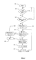
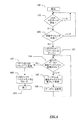
インタフェースユニット50の論理演算、詳細には、制御ユニット53の論理動作が、図3のフローチャートに関連付けて説明されている。
The logical operation of the
動作の開始(ステップ100)は、オン/オフスイッチ60によるインタフェースユニット50の電源オンを表す。肯定結果が出るまで周期的に行われるステップ101では、USBメモリキー99がコネクタCN2に接続されているか否かを制御ユニット53がチェックする。このような検出は、例えば、USBトランシーバ54を介してソフトウェアの問合せ(クエリ)によって行われることができる。
The start of the operation (step 100) represents the power-on of the
USBメモリキー99が存在する場合、次に続くステップ102では、例えば、他のユニット2,4,8,11の1つに状態情報獲得リクエスト(presence request)データパケットを送信し、応答データパケットを受信することにより、通信チャネル10への実際の接続を確認する。通信チャネル10が存在していない場合、例えば、インタフェースユニット50がコネクタCN1’に接続されていないことによって通信チャネル10が存在しない場合、実行動作はステップ101に戻る。
If the
一方、通信チャネル10が存在している場合、次に続くステップ103では、制御ユニット53が、好ましくはUSB大容量記憶プロトコル(USB Mass Storage protocol)と称される標準的なプロトコルによって規定されたものに従い、USBトランシーバ54を介してUSBメモリキーへと通信チャネルをオープンする。
On the other hand, if the
次に、データ取得サイクルが実行される。ステップ104では、全てのデータ、詳細には不揮発性データメモリ14〜17の1つに記憶されたデータまたはそのデータの一部が、通信チャネル10に接続された自転車用電子装置1の1つ以上の構成品2,4,8,11によって取得されたか否かを制御ユニット53がチェックする。このようなステップ104の第1の実行動作では上記チェックは確実に否定になる。なぜなら、USBメモリキー99およびインタフェースユニット50は接続されたばかりであり、データ取得が未だなされていないからである。したがって、次に続くステップ105において、制御ユニット53は通信チャネル10を介してデータのリクエストおよび取得を実行する。好ましくは、取得されたデータはインタフェースユニット50のバッファメモリ13の一領域に記憶され(ステップ106)、次にトランシーバ54およびコネクタCN2を介してUSBメモリキー99に送信される(ステップ107)。次に、この実行動作は、全てのデータがリクエストされたか否かをチェックするステップ104に戻る。このようなチェックが否定であれば、次のデータの取得およびUSBメモリキー99への送信のためにステップ105,106,107が再び実行される。一方、ステップ104の確認が肯定であれば、すなわち全てのデータが取得されたならば、実行動作はステップ108に進み、USBメモリキー99への通信チャネルが、好ましくは上記のUSB大量記憶プロトコルに従ってトランシーバ54を介してクローズされ、この実行動作が終了する(ステップ109)。
Next, a data acquisition cycle is executed. In
上述の動作と同時に、表示ユニット8は、例えば、「USBメモリキーが存在しています」、「データの転送を開始します」、「データの転送を終了しました」ならびに「…%のデータを転送しました」などの種類の表示、または異常の表示を用いて、転送の様々な工程の進捗を表示することができる。 Simultaneously with the above-described operation, the display unit 8 displays, for example, “USB memory key exists”, “Data transfer has started”, “Data transfer has been completed”, and “...% of data The progress of various steps of the transfer can be displayed using a type of display such as “transferred” or an anomaly display.
さらに、走行、装置の状態、診断、設定データなどがUSBメモリキー99への移動のためにインタフェースユニット50にいったん送信されると、表示ユニット8または他の構成品2,4,11は次にこれら移動された情報の削除を行うことができる。削除は自動的に行われてもよいし、または好ましくは、ステップ108でUSB通信チャネルがクローズされた後に、制御ユニット53が通信チャネル10を介して適切なデータ削除命令を送信する。いずれにせよ削除は、運転者によって入力される手動の指令に従うものであってもよい。
Further, once travel, device status, diagnosis, setting data, etc. are transmitted to the
ステップ105における、対象となるデータ「n」のリクエストおよび通信チャネル10からのこのデータの取得は、上述した半二重非同期シリアル通信プロトコルに従い、インタフェースユニット50の制御ユニット53によって2つの回線である信号線Tx/RxおよびWUで管理されてもよい。
In
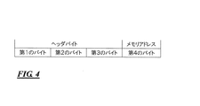
例えば、制御ユニット53は、図4に概略的に示されたリクエストデータパケットを通信チャネル10上に送信することにより、構成品2,4,8,11の1つ、例えば表示ユニット8からのデータをリクエストすることができる。このリクエストデータパケットは、符号形式のヘッダに、いずれが受信側であるか(この例では表示ユニット8)の指示と、受信側自体に対する応答において送信されるべき対象データの特定の種類の受信側への指示とを含んでいる。好ましくは、対象データの種類は、1バイト以上のデータ(例えば、応答データパケットの第4バイト)で、受信側の内部メモリである不揮発性データメモリ14〜17におけるアドレス(この例では表示ユニット8のメモリ16におけるアドレス)によって直接示されている。
For example, the
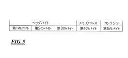
受信側(この例では表示ユニット8)は、応答において、図5に概略的に示されたデータパケットを通信チャネル10上に送信する。この応答データパケットは、ヘッダに、このデータパケットの受信側がインタフェースユニット50の制御ユニット53であるという指示を含み、データに、リクエストされたデータの数値(第5バイト)を含み、好ましくは、これと共に、このデータパケットの送信側である構成品2,4,8,11の内部メモリ14〜17におけるアドレス(この例では表示ユニット8のメモリ16におけるアドレス)の反復すなわちリクエストデータパケットにおける値と同一の値(第4バイトにおいて)を含んでいる。
The receiving side (in this example the display unit 8) transmits in response the data packet shown schematically in FIG. The response data packet includes an instruction in the header that the receiving side of the data packet is the
図3のステップ107において、USBメモリキー99に、リクエストされたデータの数値のみ、またはこの数値と、データ送信元である構成品2,4,8,11の内部メモリ14〜17におけるアドレスとを記憶させることも可能である。USBメモリキーへの記憶がバックアップ目的であり、構成品2,4,8,11における記憶内容の復元の機能が設けられる場合、これらのうち2番目の方法のほうが好ましい。
In
図6は、動作の一変形例を示しており、この変形例は、n番目のデータが取得されて記憶された(ステップ105,106,107)後に直ぐUSBメモリキーに送信されない点が、図3に関連付けて説明された動作と異なる。むしろ、対象となる全てのデータが、ステップ104,105,106の周期的実行によってまず取得されてインタフェースユニット50のバッファメモリ13に記憶され、次にステップ107において単一送信でUSBメモリキー99に転送される。
FIG. 6 shows a modified example of the operation. This modified example is that the nth data is acquired and stored (
図3または図6のフローチャートに従いUSBメモリキー99にダウンロードされたデータは、自転車用電子装置1の診断を行ったり、トレーニングの目的で、運転者の運転実績を適切なアプリケーションプログラムによって評価したりするなどのために、離れたコンピュータに後でダウンロードされることができる。
The data downloaded to the
好ましい一実施形態において、自転車用電子装置1からUSBメモリキー99へのデータ転送は、データの構造を考慮せずに、表示ユニット8のメモリ16または他の構成品2,4,11のメモリ14,15,17の選択された部分に含まれる全てのデータに関して完全に行われる。この大量のデータの正確な解釈は、アプリケーションプログラムに委ねられる。すなわち、転送されるデータは表示ユニット8に対して意味を有し、インタフェースユニット50およびUSBメモリキー99に対しては意味を有さず、コンピュータにおけるアプリケーションプログラムに対しては意味を有する。
In a preferred embodiment, the data transfer from the bicycle electronic device 1 to the
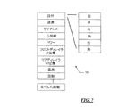
表示ユニット8にまとめて記憶され、上述された方法でUSBメモリキー99に転送される走行データ、装置の状態データ、診断データおよび設定データ等の例示的構造が、図7に示されている。各々の記録は、各センサまたは検出器によるデータ取得の時間が記憶された何日、何月、何年、何時、何分および何秒のサブフィールドを有するのが好ましい日付フィールドと、このような時間における、速度、ケイデンス、心拍数、動力、前側のディレイラの位置、後側のディレイラの位置、温度、診断値、および走行した距離などの数値のための1つ以上のフィールドとを含むレコード70に相当する。
An exemplary structure such as travel data, device status data, diagnostic data, and configuration data that are stored together on the display unit 8 and transferred to the
走行データ、装置の状態データ、診断データ、および設定データなどの記憶部が自転車用電子装置の構成品2,4,8,11に分散している場合に好適であり得る代替案では、各々の記録についてのデータ構造は、上述の形式を有する日付フィールドと、データの種類を符号化したフィールドと、このデータに係る数値とを備えている。
In alternatives that may be suitable when storage units such as travel data, device status data, diagnostic data, and setting data are distributed among
USBメモリキー99は、さらに、走行状態(ギアシフトを管理するために駆動ユニット4によって使用される)を評価するための論理パラメータ、および表示ユニット8の好ましい設定など(これらは一例でしかない)の自転車用電子装置の様々な設定パラメータの数値を当該自転車用電子装置1にダウンロードするために使用されてもよい。
The
さらなる代替案として、インタフェースユニット50に接続可能なUSBインタフェースが備えられた電子装置99は、走行データ、装置の状態データ、診断データおよび設定データなどのダウンロードや自転車用電子装置1の設定を直接行うコンピュータであってもよい。
As a further alternative, the
有利なことに、USBのコネクタCN2、および図8の実施形態の場合におけるコネクタCN1’は、さらに、充電器の接続のために使用することができ、場合によっては、自転車用電子装置1の他の構成品に電力供給するバッテリーを充電するために使用することもできる。 Advantageously, the USB connector CN2 and the connector CN1 ′ in the case of the embodiment of FIG. 8 can also be used for connection of a charger, and in some cases other than the bicycle electronic device 1 It can also be used to charge a battery that powers the components.
さらに、USBのコネクタCN2はまた、マウス、キーボード、ハードディスク大容量記憶装置、画像読取装置、デジタルカメラ、プリンタ、スピーカシステム、マイクロフォンおよびその他の接続のために使用されることができる。 In addition, the USB connector CN2 can also be used for mouse, keyboard, hard disk mass storage, image reader, digital camera, printer, speaker system, microphone and other connections.
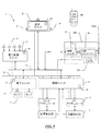
図8は、本発明の他の実施形態による自転車用電子装置1を示しており、この実施形態は、コネクタCN1’の上流における絶縁装置51を備えていない点と、ここでは参照符号150で示されているインタフェースユニットが電力供給遮断装置55を備えていない点とが図1の実施形態と異なる。
FIG. 8 shows a bicycle electronic device 1 according to another embodiment of the invention, which embodiment is not provided with an insulating
この実施形態によると、コネクタCN1’は、通信チャネル10および自転車用電子装置1の電力供給線12につながる端子を備えている。コネクタCN1は、通信チャネル10の信号線「Tx/Rx」および「WU」を制御ユニット53に接続し、電力供給線を制御ユニット53、USBトランシーバ54およびUSBのコネクタCN2の端子に接続するために、コネクタCN1’に対応する端子を備えている。インタフェースユニット150内には、必要な場合に自転車用電子装置1の電力供給線12の電圧値を、USBインタフェースが備えられた装置用の標準電力供給値(USBメモリキー99の場合は+5V)に調整するための任意のブロック155があってもよい。
According to this embodiment, the connector CN <b> 1 ′ includes terminals connected to the
このような実施形態の使用および動作は、前述した内容とほぼ同一であり、図3または図6によるデータ転送プロセスは、場合によりUSBメモリキー99が既に設けられているインタフェースユニット150がコネクタCN1’に接続され、これによりインタフェースユニット150が自転車用電子装置1の電力供給線12によって電力供給されると、直ちに開始することができる(ステップ100)。
The use and operation of such an embodiment is substantially the same as described above, and the data transfer process according to FIG. 3 or FIG. 6 is the case where the
図9は、本発明の他の実施形態による自転車用電子装置1を示しており、この実施形態は、ここでは参照符号250で示されているインタフェースユニットがコネクタによって着脱自在でなく、むしろ、自転車用電子装置1の通信チャネル10と電力供給線12とに一体化されることで恒久的に接続されている点が図8の実施形態と異なる。コネクタCN2は、図10に示されているように、第1の実施形態のコネクタCN1’に関して上述したいずれの位置に配置されてもよい。
FIG. 9 shows a bicycle electronic device 1 according to another embodiment of the present invention, in which the interface unit, here designated by
図1の実施形態で絶縁装置51の代替案として、および図8の実施形態において、電気絶縁材料、好ましくは錫からなる取外し可能なカバーなど、コネクタCN1’用の他の絶縁手段があってもよい。
As an alternative to the
図1および図8の実施形態によると、無線(ワイヤレス)による通信の場合、インタフェースユニット50または150、詳細には、その制御ユニット53に、無線送受信機が設けられ、図1の実施形態では絶縁装置51が省略される。
According to the embodiment of FIGS. 1 and 8, in the case of wireless communication, the
上述した半二重非同期シリアル通信の代替案として、構成品2,4,8,11,53間において全二重シリアル通信、同期シリアル通信、パラレル通信が確立されてもよい。
As an alternative to the half-duplex asynchronous serial communication described above, full-duplex serial communication, synchronous serial communication, and parallel communication may be established between the
さらに、自転車用電子装置1のコントローラ2,4,8,11の全てが必ずしも存在しなくてもよい。例えば、機械式のギアシフトの場合、電子制御ユニット2および駆動ユニット4、ならびにアクチュエータ3および位置検出器5は存在しない。さらに、この場合、センサ7は表示ユニット8(この場合サイクルコンピュータとしても知られる)に直接つながっていてもよいので、通信チャネル10および通信プロトコルは、表示ユニット8とインタフェースユニット50,150,250間の専用通信線に置き換えられることができる。
Further, all of the
同様に、完全に自動式のギアシフトの場合、電子制御ユニット2は存在せず、表示ユニット8も存在しない可能性がある。この場合もまた、通信チャネル10および通信プロトコルによるネットワークの形成は不必要であり得、インタフェースユニット50,150,250と、実施され得るセンサ7がつながる駆動ユニットとの間の専用通信線で十分である。
Similarly, in the case of a fully automatic gear shift, there may be no electronic control unit 2 and no display unit 8. Again, the formation of a network by means of the
自転車用電子装置1、詳細にはそのインタフェースユニット50,150,250は、USBインタフェースが備えられた装置用のポート54,CN2の代替案として、またはこのポート54,CN2に加えて、単純にコネクタで構成された、すなわちトランシーバを設ける必要のない、MiniSDもしくはMicroSD、CompactFlash、SmartMedia、MultiMediaCard、Memory Stick、Secure Digital、およびxD−Picture memoryなどの他の種類のメモリカード用のポートを備えていてもよい。
The bicycle electronic device 1, in particular its
より一般的には、自転車用電子装置1、詳細にはそのインタフェースユニット50,150,250に、他の種類のフラッシュメモリ用のポート、さらに一般的には、他の種類の取外し自在な大容量記憶装置用のポートが備えられていてもよい。
More generally, the bicycle electronic device 1, in particular its
1 自転車用電子装置
14〜17 不揮発性データメモリ
54 ポート
99 取外し自在な大容量記憶装置
CN2 ポート
1 Bicycle electronic device 14-17
Claims (29)
取外し自在な大容量記憶装置(99)用のポート(54,CN2)を備えていることを特徴とする自転車用電子装置(1)。 In a bicycle electronic device (1) comprising at least one non-volatile data memory (14-17),
A bicycle electronic device (1) comprising a port (54, CN2) for a removable mass storage device (99).
前記少なくとも1つの不揮発性データメモリ(14〜17)にアクセスする少なくとも1つのコントローラ(2,4,8,11)と、
前記少なくとも1つのコントローラ(2,4,8,11)と前記ポート(54,CN2)との間のデータ転送を管理するさらなるコントローラ(53)とを備えた自転車用電子装置(1)。 The method according to any one of claims 1 to 4, further comprising:
At least one controller (2, 4, 8, 11) accessing the at least one non-volatile data memory (14-17);
Bicycle electronic device (1) comprising a further controller (53) for managing data transfer between said at least one controller (2, 4, 8, 11) and said port (54, CN2).
前記さらなるコントローラ(53)に組み合わされたバッファメモリ(13)を備えた自転車用電子装置(1)。 In claim 5, further:
Bicycle electronic device (1) comprising a buffer memory (13) combined with the further controller (53).
前記対応するコネクタ(CN1’)が、前記インタフェースユニット(50)の前記電力供給装置(55)によって駆動可能な絶縁装置(51)を介して、当該自転車用電子装置(1)の通信チャネル(10)に接続されている自転車用電子装置(1)。 The interface unit (50) according to claim 11 or 12, further comprising a further connector (CN1) removably connectable with a corresponding connector (CN1 '),
The corresponding connector (CN1 ′) is connected to the communication channel (10) of the bicycle electronic device (1) via an insulating device (51) that can be driven by the power supply device (55) of the interface unit (50). Bicycle electronic device (1) connected to).
少なくとも1つのコントローラ(2,4,8,11)と、
前記少なくとも1つのコントローラ(2,4,8,11)と前記USBポート(54,CN2)との間の通信を管理するさらなるコントローラ(53)とを備えた自転車用電子装置(1)。 In claim 17,
At least one controller (2, 4, 8, 11);
Bicycle electronic device (1) comprising a further controller (53) for managing communication between said at least one controller (2, 4, 8, 11) and said USB port (54, CN2).
前記さらなるコントローラ(53)に組み合わされたバッファメモリ(13)を備えた自転車用電子装置(1)。 The claim 18, further comprising:
Bicycle electronic device (1) comprising a buffer memory (13) combined with the further controller (53).
前記対応するコネクタ(CN1’)が、前記インタフェースユニット(50)の前記電力供給装置(55)によって駆動可能な絶縁装置(51)を介して、当該自転車用電子装置(1)の通信チャネル(10)に接続されている自転車用電子装置(1)。 The interface unit (50) according to claim 24 or 25, further comprising a further connector (CN1) removably connectable with a corresponding connector (CN1 '),
The corresponding connector (CN1 ′) is connected to the communication channel (10) of the bicycle electronic device (1) via an insulating device (51) that can be driven by the power supply device (55) of the interface unit (50). Bicycle electronic device (1) connected to).
Applications Claiming Priority (1)
| Application Number | Priority Date | Filing Date | Title |
|---|---|---|---|
| IT002407A ITMI20072407A1 (en) | 2007-12-20 | 2007-12-20 | ELECTRONIC EQUIPMENT FOR BICYCLE |
Publications (1)
| Publication Number | Publication Date |
|---|---|
| JP2009166830A true JP2009166830A (en) | 2009-07-30 |
Family
ID=40315636
Family Applications (1)
| Application Number | Title | Priority Date | Filing Date |
|---|---|---|---|
| JP2008323497A Pending JP2009166830A (en) | 2007-12-20 | 2008-12-19 | Electronic apparatus for bicycle |
Country Status (7)
| Country | Link |
|---|---|
| US (1) | US20090170660A1 (en) |
| EP (1) | EP2072091B1 (en) |
| JP (1) | JP2009166830A (en) |
| CN (1) | CN101462579A (en) |
| AT (1) | ATE543542T1 (en) |
| IT (1) | ITMI20072407A1 (en) |
| TW (1) | TW200936435A (en) |
Cited By (3)
| Publication number | Priority date | Publication date | Assignee | Title |
|---|---|---|---|---|
| JP2014234155A (en) * | 2013-05-31 | 2014-12-15 | カンパニョーロ・ソシエタ・ア・レスポンサビリタ・リミタータCampagnolo Societa A Responsabilita Limitata | Electronic system for bicycle |
| JP2015096419A (en) * | 2013-11-15 | 2015-05-21 | カンパニョーロ・ソシエタ・ア・レスポンサビリタ・リミタータCampagnolo Societa A Responsabilita Limitata | Electronic system for bicycle |
| DE102015118149A1 (en) | 2014-10-31 | 2016-05-04 | Shimano Inc. | Bicycle control system |
Families Citing this family (18)
| Publication number | Priority date | Publication date | Assignee | Title |
|---|---|---|---|---|
| ITMI20070140A1 (en) | 2007-01-30 | 2008-07-31 | Campagnolo Srl | MAN-BICYCLE INTERACTION DEVICE |
| ITMI20070737A1 (en) | 2007-04-12 | 2008-10-13 | Campagnolo Srl | EQUIPMENT AND ELECTRONIC SYSTEM FOR BICYCLE AND RELATIVE METHODS |
| CZ308153B6 (en) * | 2009-04-01 | 2020-01-29 | Tomáš TICHÝ | Method of determining the level of physical fitness |
| US8655561B2 (en) | 2010-06-23 | 2014-02-18 | Shimano Inc. | Bicycle control system having a value generating unit |
| EP2909075A1 (en) * | 2012-10-19 | 2015-08-26 | Marquardt Verwaltungs-GmbH | Operating and/or display system |
| US9151379B2 (en) * | 2013-03-26 | 2015-10-06 | Shimano Inc. | Bicycle gear changing apparatus |
| US9191038B2 (en) * | 2013-12-24 | 2015-11-17 | Shimano Inc. | Wireless bicycle communication apparatus and wireless bicycle communication system |
| EP2979970B1 (en) * | 2014-08-01 | 2017-09-13 | Campagnolo S.R.L. | Bicycle electronic gearshift system and related method |
| JP6305322B2 (en) * | 2014-11-28 | 2018-04-04 | 株式会社シマノ | Components and communication systems |
| US10363992B2 (en) * | 2015-01-29 | 2019-07-30 | Shimano Inc. | Electric bicycle component |
| US11801913B2 (en) * | 2015-03-05 | 2023-10-31 | Shimano Inc. | Bicycle electric component setting system |
| CN104697559B (en) * | 2015-03-18 | 2017-07-25 | 百度在线网络技术(北京)有限公司 | The display methods and device for data of riding |
| JP6797188B2 (en) * | 2015-08-25 | 2020-12-09 | バイクテック アーゲーBiketec Ag | Electric bicycle |
| JP6730144B2 (en) * | 2016-09-09 | 2020-07-29 | 株式会社シマノ | Bicycle component and its communication part |
| US10472015B1 (en) * | 2018-06-28 | 2019-11-12 | Specialized Bicycle Components, Inc. | In-frame mounted bicycle monitoring device |
| CN110015374A (en) * | 2019-04-12 | 2019-07-16 | 广西信路威科技发展有限公司 | The secure operating system of bar handle vehicle |
| US11535339B2 (en) * | 2019-08-30 | 2022-12-27 | Shimano Inc. | Bicycle derailleur |
| US12589822B2 (en) | 2021-05-25 | 2026-03-31 | Specialized Bicycle Components, Inc. | In-frame mounted bicycle display |
Family Cites Families (31)
| Publication number | Priority date | Publication date | Assignee | Title |
|---|---|---|---|---|
| US1206A (en) * | 1839-06-29 | Improvement in the mode of preparing the molds for casting double pumps | ||
| JPH04104793U (en) * | 1991-02-22 | 1992-09-09 | 株式会社キヤツトアイ | Motorcycle parts |
| US5370412A (en) * | 1993-08-10 | 1994-12-06 | Chou; Ming-Fu | Ergonomically superior bicycle meter assembly |
| US5889463A (en) * | 1997-01-08 | 1999-03-30 | Judd; Dennis L. | Anti-theft device |
| US5971116A (en) * | 1997-03-13 | 1999-10-26 | Cannondale Corporation | Electronic suspension system for a wheeled vehicle |
| US6192300B1 (en) * | 1997-06-27 | 2001-02-20 | Echowell Electronic Ltd. | Bicycle computer |
| TW385005U (en) * | 1999-04-06 | 2000-03-11 | Huang Chuen Mu | Radio reception distance indicator |
| WO2001000281A2 (en) * | 1999-06-29 | 2001-01-04 | Trakus, Inc. | Performance monitoring system |
| US6204752B1 (en) * | 1999-11-24 | 2001-03-20 | Shimano Inc. | Bicycle display unit with backlight |
| JP3827273B2 (en) * | 1999-12-24 | 2006-09-27 | Ykk株式会社 | Ultrasonic bonding method and apparatus |
| IT1320286B1 (en) * | 2000-03-29 | 2003-11-26 | Campagnolo Srl | MULTIPROCESSOR CONTROL SYSTEM FOR CYCLES, FOR EXAMPLE COMPETITION BICYCLES. |
| IT1320405B1 (en) * | 2000-06-06 | 2003-11-26 | Campagnolo Srl | ELECTRIC CONTROL DEVICE FOR A MOTORIZED FRONT DERAILLEUR. |
| EP1450905A2 (en) * | 2001-11-30 | 2004-09-01 | AWS Technology ApS | Bicycle trainer |
| JP2003327059A (en) * | 2002-03-08 | 2003-11-19 | Calsonic Kansei Corp | Input device for vehicle |
| JP3872371B2 (en) * | 2002-03-29 | 2007-01-24 | セイコーインスツル株式会社 | Portable biological information collecting apparatus, biological information collecting system, and biological information collecting method |
| US7116008B2 (en) * | 2002-04-23 | 2006-10-03 | Shimano, Inc. | Electrical communication system for a bicycle |
| US6724299B2 (en) * | 2002-06-27 | 2004-04-20 | Shimano, Inc. | Bicycle data communication method and apparatus |
| US6781510B2 (en) * | 2002-07-24 | 2004-08-24 | Shimano, Inc. | Bicycle computer control arrangement and method |
| US6844845B1 (en) * | 2003-01-06 | 2005-01-18 | Garmin Ltd. | Waterproof combined global positioning system receiver and two-way radio and method of waterproof enclosure fabrication |
| JP3777360B2 (en) * | 2003-03-27 | 2006-05-24 | 株式会社シマノ | Bicycle information processing device |
| WO2004087490A2 (en) * | 2003-03-28 | 2004-10-14 | Acres John F | Integrated power, lighting, and instrumentation system for bicycles |
| ATE312750T1 (en) | 2003-07-24 | 2005-12-15 | Campagnolo Srl | METHOD FOR SHIFTING A BICYCLE TRANSMISSION WITH ELECTRICAL AUXILIARY DRIVE AND SHIFTING DEVICE |
| TWM247237U (en) * | 2003-11-27 | 2004-10-21 | Chang Yow Industry Co Ltd | Control system for exercise device |
| US7132931B2 (en) * | 2004-02-17 | 2006-11-07 | Shimano Inc. | Bicycle computer and handlebar assembly with bicycle computer |
| US20050195094A1 (en) * | 2004-03-05 | 2005-09-08 | White Russell W. | System and method for utilizing a bicycle computer to monitor athletic performance |
| WO2006023816A1 (en) * | 2004-08-19 | 2006-03-02 | Saris Cycling Group, Inc. | Wireless wheel-speed and cadence detection method and system |
| US20070161459A1 (en) * | 2005-12-20 | 2007-07-12 | Watson Edward M | Multi-functional USB exercise data storage device |
| DE102006019385A1 (en) * | 2006-04-26 | 2007-10-31 | Hans Egermeier | Physical training and mental stimulation method for maintaining or improving physical and mental fitness, involves carrying out recognition and response system according to predetermination of right parameters by system |
| ITMI20070140A1 (en) * | 2007-01-30 | 2008-07-31 | Campagnolo Srl | MAN-BICYCLE INTERACTION DEVICE |
| ITMI20070737A1 (en) * | 2007-04-12 | 2008-10-13 | Campagnolo Srl | EQUIPMENT AND ELECTRONIC SYSTEM FOR BICYCLE AND RELATIVE METHODS |
| ITMI20071181A1 (en) * | 2007-06-12 | 2008-12-13 | Campagnolo Srl | ELECTRONIC CONTROL METHOD OF A BICYCLE CHANGE AND ELECTRONIC BICYCLE SYSTEM |
-
2007
- 2007-12-20 IT IT002407A patent/ITMI20072407A1/en unknown
-
2008
- 2008-03-22 AT AT08005414T patent/ATE543542T1/en active
- 2008-03-22 EP EP08005414A patent/EP2072091B1/en not_active Not-in-force
- 2008-12-19 JP JP2008323497A patent/JP2009166830A/en active Pending
- 2008-12-19 US US12/339,833 patent/US20090170660A1/en not_active Abandoned
- 2008-12-19 TW TW097149794A patent/TW200936435A/en unknown
- 2008-12-22 CN CNA2008101884165A patent/CN101462579A/en active Pending
Cited By (6)
| Publication number | Priority date | Publication date | Assignee | Title |
|---|---|---|---|---|
| JP2014234155A (en) * | 2013-05-31 | 2014-12-15 | カンパニョーロ・ソシエタ・ア・レスポンサビリタ・リミタータCampagnolo Societa A Responsabilita Limitata | Electronic system for bicycle |
| JP2014237435A (en) * | 2013-05-31 | 2014-12-18 | カンパニョーロ・ソシエタ・ア・レスポンサビリタ・リミタータCampagnolo Societa A Responsabilita Limitata | Electronic system for bicycle |
| JP2015096419A (en) * | 2013-11-15 | 2015-05-21 | カンパニョーロ・ソシエタ・ア・レスポンサビリタ・リミタータCampagnolo Societa A Responsabilita Limitata | Electronic system for bicycle |
| DE102015118149A1 (en) | 2014-10-31 | 2016-05-04 | Shimano Inc. | Bicycle control system |
| DE102015118149B4 (en) | 2014-10-31 | 2026-02-19 | Shimano Inc. | Bicycle control system |
| DE102015017511B4 (en) | 2014-10-31 | 2026-03-12 | Shimano Inc. | Bicycle control system |
Also Published As
| Publication number | Publication date |
|---|---|
| TW200936435A (en) | 2009-09-01 |
| US20090170660A1 (en) | 2009-07-02 |
| ITMI20072407A1 (en) | 2009-06-21 |
| ATE543542T1 (en) | 2012-02-15 |
| EP2072091B1 (en) | 2012-02-01 |
| EP2072091A1 (en) | 2009-06-24 |
| CN101462579A (en) | 2009-06-24 |
Similar Documents
| Publication | Publication Date | Title |
|---|---|---|
| JP2009166830A (en) | Electronic apparatus for bicycle | |
| US7200447B2 (en) | Multiprocessor control system for cycles, for example for competition bicycles | |
| TWI633035B (en) | Bicycle electronic system (1) | |
| CN102402099B (en) | Interchangeable lens and camera main-body | |
| US8905814B2 (en) | Electronic speed control programming | |
| CN106394801B (en) | Operation control device and display device for bicycle | |
| US20070161459A1 (en) | Multi-functional USB exercise data storage device | |
| US8217627B2 (en) | System and method for managing power to an electronic apparatus on-board a bicycle | |
| GB2583591A (en) | Universal protocol for power tools | |
| CN113749723A (en) | Intraosseous device and data transmission | |
| WO2009063894A1 (en) | Server system, game device, control method, program, and information storage medium | |
| JP2015000248A (en) | Game machine | |
| JP5368255B2 (en) | Game machine | |
| JP2015096419A (en) | Electronic system for bicycle | |
| JP5530410B2 (en) | Operation method between in-vehicle unit and mobile device, and in-vehicle unit system | |
| JP6505146B2 (en) | Gaming machine | |
| CN115605854A (en) | Provides acknowledgment for the system power management interface | |
| CN100481895C (en) | Method and device for carrying out TV set software upgrade | |
| JP2006068298A (en) | Game machine | |
| CN205383095U (en) | Intelligent electric fan | |
| JP4502735B2 (en) | Electric sewing machine | |
| JP2005128888A (en) | Command processing apparatus and control method for command processing apparatus | |
| CN105604971A (en) | Intelligent fan | |
| KR200475844Y1 (en) | The Auto Mobile | |
| CN201503637U (en) | Concentrator of ARM |