JP2009178014A - Charger - Google Patents
Charger Download PDFInfo
- Publication number
- JP2009178014A JP2009178014A JP2008016969A JP2008016969A JP2009178014A JP 2009178014 A JP2009178014 A JP 2009178014A JP 2008016969 A JP2008016969 A JP 2008016969A JP 2008016969 A JP2008016969 A JP 2008016969A JP 2009178014 A JP2009178014 A JP 2009178014A
- Authority
- JP
- Japan
- Prior art keywords
- charging
- signal
- microcomputer
- battery
- voltage
- Prior art date
- Legal status (The legal status is an assumption and is not a legal conclusion. Google has not performed a legal analysis and makes no representation as to the accuracy of the status listed.)
- Granted
Links
Images

Classifications
-
- Y—GENERAL TAGGING OF NEW TECHNOLOGICAL DEVELOPMENTS; GENERAL TAGGING OF CROSS-SECTIONAL TECHNOLOGIES SPANNING OVER SEVERAL SECTIONS OF THE IPC; TECHNICAL SUBJECTS COVERED BY FORMER USPC CROSS-REFERENCE ART COLLECTIONS [XRACs] AND DIGESTS
- Y02—TECHNOLOGIES OR APPLICATIONS FOR MITIGATION OR ADAPTATION AGAINST CLIMATE CHANGE
- Y02E—REDUCTION OF GREENHOUSE GAS [GHG] EMISSIONS, RELATED TO ENERGY GENERATION, TRANSMISSION OR DISTRIBUTION
- Y02E60/00—Enabling technologies; Technologies with a potential or indirect contribution to GHG emissions mitigation
- Y02E60/10—Energy storage using batteries
Landscapes
- Secondary Cells (AREA)
- Charge And Discharge Circuits For Batteries Or The Like (AREA)
Abstract
【課題】リチウムイオン電池の過充電状態を確実に検出して高い安全性を確保することができる充電装置を提供すること。
【解決手段】電池パック2aから出力される電池状態を報知する信号を受信し、その信号の内容に応じて充電の可否を判断・決定するマイコン50と、該マイコン50の充電可否の判断に応じて充電の開始・停止を制御する充電停止手段(リレー120)と、前記マイコン50とは別に、前記信号を受信して前記充電停止手段を制御する充電停止制御回路(FET127、抵抗126)を有する充電装置において、前記信号を前記マイコン50及び前記充電停止制御回路が受信して充電を停止すると判断した場合、前記充電停止制御回路によって前記充電停止手段を制御して充電を停止させる動作を、前記マイコン50による充電停止の判断・決定よりも遅延させるようにする。
【選択図】図1A charging device capable of reliably detecting an overcharged state of a lithium ion battery and ensuring high safety.
A microcomputer 50 that receives a battery state notification signal output from a battery pack 2a and determines / determines whether charging is possible according to the contents of the signal, and according to whether the microcomputer 50 determines whether charging is possible In addition to the microcomputer 50, a charge stop control circuit (FET 127, resistor 126) that receives the signal and controls the charge stop means is provided separately from the microcomputer 50. In the charging apparatus, when the microcomputer 50 and the charge stop control circuit receive the signal and determine that the charge is stopped, the charge stop control circuit controls the charge stop means to stop the charge, The delay is made rather than the determination / determination of the charging stop by the microcomputer 50.
[Selection] Figure 1
Description
本発明は、リチウムイオン電池等の2次電池を充電するための充電装置に関するものである。 The present invention relates to a charging device for charging a secondary battery such as a lithium ion battery.
例えば、コードレス電動工具の駆動源であるモータに電力を供給する電源として充電可能な2次電池が使用されているが、この2次電池には更なる高容量化と軽量化が望まれている。この要望に対して、出力密度が高いリチウムイオン電池が普及してきている。 For example, a rechargeable secondary battery is used as a power source for supplying power to a motor that is a drive source of a cordless power tool. Further increase in capacity and weight reduction is desired for this secondary battery. . In response to this demand, lithium ion batteries having a high output density have become widespread.
ところで、リチウムイオン電池は、過充電・過放電によって劣化や発火の可能性があり、特許文献1記載のように、一般的には電池パック内に専用の保護ICやマイコンを設けて過放電・過電圧を監視し、電池電圧が所定値以下又は以上の場合は、前記専用の保護ICやマイコンが信号を出力し、この信号に基づいて充放電経路を遮断してしまうという安全性に対する対策が採られている。
しかし、例えば、電池パック内に保護ICを設け、該保護ICからの信号に対応して充電装置に設けられたマイコン及び該マイコンとは別の独立した制御回路が充電装置内の充電停止手段を制御し、過充電時には充電を停止する二重の充電停止制御手段が設けられている場合には、状況によっては確実に過充電状態時に充電を停止することができない可能性があるという問題がある。このことを以下に説明する。 However, for example, a protection IC is provided in the battery pack, a microcomputer provided in the charging device corresponding to a signal from the protection IC, and an independent control circuit different from the microcomputer provide a charging stop means in the charging device. If there is a double charge stop control means that controls and stops charging when overcharged, there is a problem that depending on the situation, there is a possibility that charging may not be stopped reliably when overcharged . This will be described below.
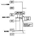
一般的に電池の保護ICは、電池のセル毎の電圧を1つ1つ監視し、多数あるセルのうち1つでも電圧が或る所定値以上に達した場合に過電圧であると判断して信号を出力する。ここで、過電圧であると判断する電圧を例えば4.25Vであるとする。そして、充電装置は、電池パックから過電圧である(1セルでも4.25Vを超えた)との信号を受信すると充電が停止する構成になっているものとする。停止した後には電池には電流が流れなくなるため、電池電圧は過電圧であると判断した4.25Vから降下する。 In general, a battery protection IC monitors the voltage of each battery cell one by one, and judges that the voltage is overvoltage when even one of a large number of cells reaches a predetermined value or more. Output a signal. Here, it is assumed that the voltage determined to be an overvoltage is, for example, 4.25V. The charging device is configured to stop charging when it receives a signal from the battery pack that it is overvoltage (over one cell exceeds 4.25 V). After the stop, no current flows through the battery, so the battery voltage drops from 4.25 V determined to be an overvoltage.
一般的に電池の保護ICは4.25Vから電圧が降下した後も、或る所定電圧以下に降下するまでは過電圧であると判断する信号を出力し続ける。例えば、4.25Vから100mV降下するまで信号を出力し続けるものとする。即ち、電池が4.25Vに達することによって過電圧であると判断されて充電を停止し、その後、4.15V(100mV降下)以下になるまでは過電圧であると判断する信号を出力し続ける。 Generally, even after the voltage drops from 4.25 V, the battery protection IC continues to output a signal that determines that it is an overvoltage until it drops below a certain predetermined voltage. For example, it is assumed that the signal is continuously output from 4.25V to 100mV. That is, when the battery reaches 4.25 V, it is determined that the battery is overvoltage, and charging is stopped. Thereafter, a signal that determines that the battery is overvoltage is continuously output until the battery voltage becomes 4.15 V (100 mV drop) or less.
ここで、保護ICからの信号に対応して充電装置に設けられたマイコン及び該マイコンとは別の独立した制御回路が充電装置内の充電停止手段を制御し、過充電時には充電を停止するという二重の充電停止制御手段が設けられている場合について考える。 Here, a microcomputer provided in the charging device corresponding to a signal from the protection IC and an independent control circuit different from the microcomputer control the charging stop means in the charging device, and stop charging when overcharged. Consider a case where double charge stop control means is provided.
電池が過電圧に達し、過電圧であると判断する信号が電池パックから出力された際に、マイコンはこの信号を受信して充電を停止する決定を行うが、マイコンがこの信号を受信したとの判断には或る時間が必要となる。例えば、信号受信に際して、マイコンは或るサンプリング時間の間隔で信号を受信するが、このサンプリング間隔を5m秒とする。或るサンプリング時に過電圧であると判断する信号を受信し、その1回の受信において過電圧であると判断するのはノイズ等の要素を考えると不確実である。よって、例えば10回連続で過電圧であるとの信号を受信した場合は過電圧であると判断すればより確実になる。 When the battery reaches overvoltage and a signal that determines that it is overvoltage is output from the battery pack, the microcomputer receives this signal and decides to stop charging, but determines that the microcomputer has received this signal. Requires some time. For example, when receiving a signal, the microcomputer receives a signal at a certain sampling time interval, and this sampling interval is set to 5 milliseconds. It is uncertain to receive a signal that determines an overvoltage at a certain sampling time and to determine that it is an overvoltage in a single reception in view of factors such as noise. Therefore, for example, when a signal indicating an overvoltage is received ten times consecutively, it is more reliable if it is determined that the overvoltage occurs.
しかし、10回連続をカウントするには、サンプリング間隔が5m秒であるとすると5m秒×10回=50m秒の時間が必要となる。このとき、前述のマイコンとは別の独立した制御回路は、マイコンの判断とは無関係に充電停止手段を制御して充電を停止しようとする。 However, in order to count 10 consecutive times, if the sampling interval is 5 ms, a time of 5 ms × 10 times = 50 ms is required. At this time, an independent control circuit different from the above-described microcomputer attempts to stop charging by controlling the charging stop means irrespective of the judgment of the microcomputer.
ここで、マイコンの停止判断よりも、前記充電停止手段における充電停止の制御が速い場合(過電圧であるとの信号が出力された後、50m秒以下の速さで停止してしまった場合)を考える。このとき、充電停止手段において充電が停止(マイコンはこのとき充電を停止するとの判断を下していない)されると電圧が降下する。このとき、前述したように4.15Vまで電圧が降下しなければ電池パックから信号が出力され続けるが、4.15Vまで降下した場合は信号が出力されなくなる。このとき、前述したマイコンが過電圧であると判断するのに必要な時間50m秒以内に4.15Vまで降下してしまった場合には、マイコンは過電圧であると判断することができない。 Here, the case where the charge stop control in the charge stop means is faster than the microcomputer stop determination (when the signal indicating that it is an overvoltage is output and then stopped at a speed of 50 milliseconds or less). Think. At this time, when charging is stopped by the charging stop means (the microcomputer has not made a determination to stop charging at this time), the voltage drops. At this time, as described above, if the voltage does not drop to 4.15V, the signal continues to be output from the battery pack, but if it drops to 4.15V, the signal is not output. At this time, if the voltage drops to 4.15 V within 50 milliseconds required to determine that the microcomputer is overvoltage, the microcomputer cannot be determined to be overvoltage.
前述のように、マイコンが過電圧であると判断する前にこれとは別の充電停止制御手段が充電を停止し、マイコンが過電圧であると判断する前に電圧が4.15Vまで降下してしまう場合には、過電圧の信号は出力されなくなり、過充電停止手段による充電の停止も解除されて再び充電が行われる。その後、充電によって電池電圧が再度4.25V以上に達して一旦充電が停止するが、マイコンは認識できないで充電が繰り返される可能性がある。 As described above, before the microcomputer determines that the voltage is overvoltage, another charge stop control means stops charging, and the voltage drops to 4.15 V before the microcomputer determines that the voltage is overvoltage. In such a case, the overvoltage signal is not output, the charge stoppage by the overcharge stop means is canceled, and charging is performed again. Thereafter, the battery voltage again reaches 4.25 V or more due to charging, and charging is temporarily stopped. However, there is a possibility that the microcomputer cannot be recognized and charging is repeated.
一方、保護ICが過電圧であると判断する4.25Vに達してから信号を出力するまでには或る時間を要する。このことは、前述したマイコンが信号を受信して過電圧であると判断するために時間を要する理由と同様である。このため、実際には設定値である4.25Vを若干ながら超えてから過電圧信号を出力することになる。数回程度4.25Vを若干超えて充電する程度であれば特に問題はないが、前述したようにこの動作が繰り返されると、設定値である4.25Vを大きく超えてしまう場合がある(図4参照)。このような現象は充電電流を停止した後の電圧の降下が大きい状態において起こり易い。例えば、低温時に電池を充電したり、寿命間近の電池を充電すると、通常よりも内部抵抗が高い状態であるために電圧の上昇が高いが、充電を停止した後の電圧降下も大きいためにこのような現象が起こり得る可能性がある。 On the other hand, it takes a certain time until the signal is output after the protection IC reaches 4.25 V which is determined to be an overvoltage. This is the same as the reason why it takes time for the microcomputer to receive a signal and determine that it is an overvoltage. For this reason, the overvoltage signal is actually output after slightly exceeding the set value of 4.25V. There is no particular problem as long as the battery is charged a little over 4.25V for several times, but if this operation is repeated as described above, it may greatly exceed the set value of 4.25V (see FIG. 4). Such a phenomenon is likely to occur in a state where the voltage drop is large after the charging current is stopped. For example, when charging a battery at low temperatures or charging a battery that is nearing the end of its life, the internal resistance is higher than usual and the voltage rises high, but the voltage drop after stopping charging is also large. Such a phenomenon may occur.
本発明は上記問題に鑑みてなされたもので、その目的とする処は、リチウムイオン電池の過充電状態を確実に検出して高い安全性を確保することができる充電装置を提供することにある。 The present invention has been made in view of the above problems, and an object thereof is to provide a charging device that can reliably detect an overcharged state of a lithium ion battery and ensure high safety. .
上記目的を達成するため、請求項1記載の発明は、
保護回路を有する電池パックを充電する充電装置であって、
前記保護回路からの電池状態を報知する信号を受信することで充電停止する遮断手段と、
前記電池状態を報知する信号に基づいて充電動作の可否を判断する判断手段と、を備え、
前記判断手段による充電動作の可否よりも前記充電停止手段の動作を遅延させることを特徴とする。
In order to achieve the above object, the invention according to claim 1
A charging device for charging a battery pack having a protection circuit,
A blocking means for stopping charging by receiving a signal informing the battery state from the protection circuit;
Determination means for determining whether or not a charging operation is possible based on a signal for informing the battery state;
It is characterized in that the operation of the charging stop means is delayed more than the possibility of the charging operation by the judging means.
請求項2記載の発明は、請求項1記載の発明において、前記遮断手段は、電池パックからの信号の入力に伴うスイッチング動作により充電を停止させるスイッチング素子を含んで構成されており、
前記スイッチング素子に入力される前記電池状態を報知する信号を遅延させる遅延回路を備えたことを特徴とする。
The invention according to claim 2 is the invention according to claim 1, wherein the blocking means includes a switching element that stops charging by a switching operation accompanying input of a signal from the battery pack,
A delay circuit for delaying a signal for reporting the battery state input to the switching element is provided.
請求項3記載の発明は、請求項1又は2記載の発明において、前記電池状態を報知する信号は、電池パックの電池電圧が所定値以上に達して過電圧であるか否かを報知する内容の信号であって、前記マイコン及び充電停止制御回路は前記電池パックからの信号が過電圧であることを示す内容であると判断したときには、充電を停止する動作を行うことを特徴とする。 According to a third aspect of the present invention, in the first or second aspect of the present invention, the signal for informing the battery state informs whether or not the battery voltage of the battery pack reaches a predetermined value or more and is an overvoltage. If the microcomputer and the charge stop control circuit determine that the signal from the battery pack indicates an overvoltage, the microcomputer and the charge stop control circuit perform an operation to stop charging.
本発明によれば、電池パックから出力される電池状態を報知する信号をマイコン及び充電停止制御回路が受信して充電を停止すると判断した場合、充電停止制御回路によって充電停止手段を制御して充電を停止させる動作を、マイコンによる充電停止の判断・決定よりも遅延させるようにしたため、リチウムイオン電池の過充電状態を検出したときに該リチウムイオン電池の充電を確実に停止させることができ、高い安全性を確保することができる。 According to the present invention, when the microcomputer and the charge stop control circuit receive the signal that informs the battery state output from the battery pack and determine that the charge is stopped, the charge stop control circuit controls the charge stop means to perform charging. Since the operation to stop the battery is delayed from the determination / determination of the charge stop by the microcomputer, when the overcharge state of the lithium ion battery is detected, the charge of the lithium ion battery can be stopped reliably, and high Safety can be ensured.
以下に本発明の実施の形態を添付図面に基づいて説明する。 Embodiments of the present invention will be described below with reference to the accompanying drawings.
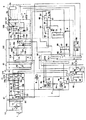
図1は本発明に係る充電装置の回路図であり、同図において、1は交流電源、2は組電池及び保護ICを含む電池パック、2aは複数の素電池を直列接続して成る組電池である。2bは電池電圧を監視して過充電或いは過放電を検知すると信号を出力する保護ICであり、この保護IC2bはセル毎の電圧を監視し、複数のセルのうち1つでも所定電圧を超えた場合は過電圧であると判断する。 FIG. 1 is a circuit diagram of a charging apparatus according to the present invention, in which 1 is an AC power source, 2 is a battery pack including an assembled battery and a protection IC, and 2a is an assembled battery formed by connecting a plurality of unit cells in series. It is. 2b is a protection IC that monitors the battery voltage and outputs a signal when overcharge or overdischarge is detected. This protection IC 2b monitors the voltage for each cell, and even one of a plurality of cells exceeds a predetermined voltage. In the case, it is determined that the voltage is overvoltage.
3は電池パック2aに流れる充電電流を検出する電流検出手段であるシャント抵抗、4はマイコン50の出力ポート51aからの信号に応じてSW制御IC23を停止させるためのスイッチング停止手段であり、ホトカプラ4aと抵抗4b,4c,4d及びトランジスタ4eによって構成されている。5は充電電流及び充電電圧の信号をSW制御IC23に帰還する充電電流信号伝達手段であり、ホトカプラ等で構成されている。
6は充電の状態を表示するための表示手段であり、LED6aと抵抗6b,6cによって構成されている。ここで、LED6aは赤と緑と橙の3色を発色できるような構成のものであり、赤は充電前を表し、橙は充電中を表し、緑は充電終了後を表すものとする。
7はセル数判別抵抗であり、セル数判別回路9の抵抗と基準値であるVccの値を分圧する機能を有している。そして、分圧された値は、マイコン50のA/Dポート52に入力され、その値に基づいてマイコン50はセル数を判別する。8は電池パック2aに近接して設けられたサーミスタ等の感温素子である。
Reference numeral 7 denotes a cell number discrimination resistor, which has a function of dividing the resistance of the cell number discrimination circuit 9 and the reference value Vcc. The divided value is input to the A /
10は全波整流回路11と平滑用コンデンサ12から成る整流平滑回路である。20は高周波トランス21、MOSFET22とSW制御IC23、SW制御IC用定電圧回路24、起動抵抗25、スイッチングIC停止用入力端子に連なるプルアップ抵抗26から成るスイッチング回路であり、高周波トランス21は、1次巻線21a、2次巻線21b、3次巻線21c及び4次巻線21dから成り、直流の入力電圧が印加される1次巻線21aに対して、2次巻線21bはSW制御IC23用の出力巻線、3次巻線21cは電池パック2を充電するための出力巻線、4次巻線21dは2次側のIC類の電源用出力巻線である。尚、1次巻線21aに対して、2次巻線21bと4次巻線21dは、同極性で3次巻線21cは逆極性である。
A rectifying / smoothing
SW制御IC23は、MOSFET22の駆動パルス幅を変えて出力電圧を調整するスイッチング電源ICである。又、SW制御IC用定電圧回路24は、ダイオード24aと3端子レギュレータ24b及びコンデンサ24c,24dから構成されており、2次巻線21bからの出力電圧を定電圧化する機能を有している。又、SW制御IC23は、通常状態においてはプルアップ抵抗26に連なるスイッチングIC停止用入力端子に抵抗26を介して電源電圧が入力されているが、スイッチング停止手段4においてトランジスタ4eがオンすることによって0Vが入力されるとスイッチング動作が停止し、電源電圧を入力する端子の電圧が或る所定電圧以下にならない限り停止状態が解除されないような仕様になっている。即ち、スイッチング動作を一旦停止したSW制御IC23を復帰させるには、充電装置のコンセントを抜かなければならないような仕様になっている。スイッチング動作の停止は、例えばフィードバック系が故障していて無制御状態になっているために過大な充電電流を検出した場合等において行う。
The
30は整流平滑回路であり、これはダイオード31と平滑コンデンサ32及び放電用抵抗33によって構成されている。
40はダイオード111、コンデンサ42,43、3端子レギュレータ44及びリセットポート45から構成される定電圧回路であり、これは2次側のIC類の電源となるものである。
50はマイコン(マイクロコンピュータ)であり、これは出力ポート51a,51bとA/Dポート52及びリセットポート53によって構成されている。
60はオペアンプ61,65と抵抗62,63,64,66,67及びダイオード68から成る充電電流制御回路である。
A charging
70は充電電流設定手段であり、抵抗71,72によって構成されている。ここで、基準電圧Vccが抵抗71,72によって分圧された値が充電電流を設定する際の基準値となる。
80は電池温度検出手段であり、抵抗81,82によって構成されている。ここで、基準電圧Vccは、感温素子8及び抵抗82の並列抵抗と抵抗81によって分圧され、その値がマイコン50のA/Dポート52に電池温度情報として入力される。
90は電池電圧検出手段であり、抵抗91,92によって構成されている。電池電圧は抵抗91,92によって分圧され、その値がマイコン50のA/Dポート52に電池電圧情報として入力される。
100は充電電圧制御手段であり、抵抗101,103,105,106,107,108,109、ポテンショメータ102、コンデンサ104、シャントレギュレータ110、整流ダイオード111及びFET112によって構成されている。充電電圧は、抵抗101とポテンショメータ102の直列抵抗と、抵抗105,106,109及びFET112との分圧値がシャントレギュレータ110の基準値となるように定められる。例えば、抵抗101、ポテンショメータ102の直列抵抗と、抵抗105とで定められる値は4セルのリチウムイオン電池を充電するための値、抵抗105と抵抗106の並列抵抗(FET112をオンさせることによる並列抵抗)とで定められる値は、5セルのリチウムイオン電池を充電するための値と定める。このようにしてセル数に対応して高精度な電圧を出力することができる構成になっている。
120は充電経路開閉手段であるリレーであり、このリレー120には、逆電圧防止のためのダイオード121が設置されており、そのオン・オフの制御はマイコン50の出力ポート51bを介して行われる。即ち、リレー120のオンは、マイコン50の出力ポート51bよりハイ信号を出力し、ダイオード129を介してFET122をオンすることによって行われる。又、リレー120のオフは、逆にマイコン50の出力ポート51bよりロー信号を出力し、ダイオード129を介してFET122をオフすることによって行われる。
FET122のゲートには、ゲートに入力される信号を遅延させるためのコンデンサ124と抵抗125及び放電のための抵抗123が接続されている。又、リレー120は、電池パック2に設置された保護IC2bからの信号によってもオフされ得る構成になっている。ここで、保護IC2bは通常状態においてはロー信号を出力し、過電圧であると判別した場合はハイ信号を出力するものとする。通常状態にあり、保護IC2bがロー信号を出力している場合は、FET127はオフ状態にあり、ダイオード130のカソード側は抵抗128を介してVcc相当の電圧が印加されている。又、このVcc相当の電圧はマイコン50のA/Dポート52にも入力される。マイコン50は、A/Dポート52にVcc相当の値が入力されている場合は通常状態と判断するものとする。
A
一方、通常状態においては、電池の充電電流を供給するためにマイコン50の出力ポート51bからはリレー120をオンするためハイ信号が出力されている。この場合、通常状態において、保護IC2bからのロー信号が出力される結果としてダイオード130のカソードに印加される電圧は、マイコン50によって制御されるリレー120の動作には何ら影響を与えることはない。
On the other hand, in the normal state, a high signal is output from the output port 51b of the
他方、過充電状態にあり、保護IC2bがロー信号を出力している場合は、FET127のゲートには抵抗126を介してVccが印加されるためにオン状態となり、ダイオード130のカソード側はグランドと同電位(即ち、0V)となる。又、この電圧はマイコン50のA/Dポート52にも入力される。マイコン50は、A/Dポート52に0Vが入力されている場合は過電圧状態と判断するものとする。
On the other hand, when the protection IC 2b is outputting a low signal in the overcharged state, Vcc is applied to the gate of the FET 127 via the
通常であれば、マイコン50は保護IC2bからの信号がA/Dポート52に入力されればマイコン50はリレー120をオフし充電を停止する。万一、マイコン50及び周辺回路の何らかの異常によりマイコン50の出力ポート51bからリレー120をオンするため、ハイ信号が出力され続けた場合にも、ダイオード130のカソード側はグランド電位になっており、マイコン50の出力ポート51bのリレー120をオンするためのハイ信号はグランド電位に落ちるため、リレー120をオンすることができない。このようにマイコン50に何らかの異常が生じてリレー120を制御できなくなっても、別回路でリレー120を制御することによって二重の制御を行う構成になっている。
Normally, the
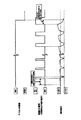
マイコン50が過電圧と認識するよりも、前述した別回路が過電圧を認識する方が速い場合は、ケースによっては、過充電状態に陥ってしまう可能性がある。このため、前述のようにFET122のゲートには、該ゲートに入力される信号を遅延させるためのコンデンサ124と抵抗125及び放電のための抵抗123が接続されており、マイコン50の方がより速く過電圧であることを認識することができるようになっており、確実に過電圧を検出することができる(図2参照)。
If it is faster for the above-described separate circuit to recognize the overvoltage than the
次に、充電制御の流れを図3のフローチャートに従って説明する。 Next, the flow of charge control will be described with reference to the flowchart of FIG.
先ず、電源を投入するとマイコン50は出力ポート51a及び52bをイニシャルセットする。次に、表示手段6において、充電前であることを表示する。本実施の形態においては、表示手段6の抵抗6bに連なるマイコン50の出力ポート51aからハイ信号を出力し、表示手段6を赤点灯させることにより充電前であることを表示する(ステップ401)。次に、電池が充電器に接続されたか否かを判別する(ステップ402)。電池の接続は例えば、電池温度検出手段80を介して入力されるマイコン50のA/Dポート52の値に変化があった場合に電池が接続されたとすれば良い。次に、セル数判別手段9を介して入力されるマイコン50のA/Dポート52の値よりセル数を判別する(ステップ403)。次に、ステップ403において判別したセル数に応じて出力電圧を設定する(ステップ404)。
First, when the power is turned on, the
本実施の形態においては、FET112をオフすることによる4セルの出力設定を行い、FET112をオンすることによって5セルの出力設定を行う。
In this embodiment, the output setting of 4 cells is performed by turning off the
次に、出力ポート51aよりハイ信号を出力し、FET122をオンすることによってリレー120をオンして充電を開始する(ステップ405)。充電を開始すると表示手段6によって充電中であることを表示する(ステップ406)。表示手段6の抵抗6b及び6cに連なる出力ポート51aよりハイ信号出力し橙点灯させることで充電中であることを表示する。
Next, a high signal is output from the output port 51a and the
次に、保護IC2bからの信号によってマイコン50のA/Dポート52に0Vが入力されているか否かによって電池が過充電状態にあるか否かを判別する(ステップ407)。ステップ407において、過充電状態であると判別した場合は、出力ポート51bよりロー信号を出力し、FET122をオフすることによってリレー120をオフして充電を停止する(ステップ409)。このとき、マイコン50等に何らかの異常があって充電が停止しない場合であっても、マイコン50とは別回路からの信号によりリレー120がオフするような二重の保護構造になっていることは前述した通りである。
Next, it is determined whether or not the battery is in an overcharged state based on whether or not 0V is input to the A /
次に、充電電流が所定値以下か否かを判別する(ステップ408)。本実施の形態に係る充電装置は定電流・定電圧充電制御を行っており、或る所定の電圧に達すると充電電流が降下していく。その後、或る所定電流まで降下した場合を満充電と判別するもとのとする。ステップ408において、充電電流が所定値以下に達した場合は満充電と判別し、マイコン50の出力ポート51bよりロー信号を出力し、FET122をオフすることによってリレー120をオフして充電を停止する(ステップ409)。充電停止後の表示手段6の表示は緑点灯である(ステップ410)。緑点灯させるためには、表示手段6の抵抗6cに連なる出力ポート51aよりハイ信号出力させる。その後、電池が充電器から抜けた場合(ステップ411)はステップ401に処理が戻る。
Next, it is determined whether or not the charging current is a predetermined value or less (step 408). The charging apparatus according to the present embodiment performs constant current / constant voltage charging control, and the charging current decreases when a certain predetermined voltage is reached. Thereafter, a case where the current drops to a predetermined current is determined as a full charge. In
以上のように、本実施の形態によれば、FET122のゲートに、該ゲートに入力される信号を遅延させるためのコンデンサ124と抵抗125及び放電のための抵抗123を接続し、マイコン50の方がより速く過電圧であることを認識することができるようにしたため、電池パック2aの各セル(リチウムイオン電池)の過電圧を検出して充電を確実に停止させることができ、これによって高い安全性を確保することができる。
As described above, according to the present embodiment, the
尚、本実施の形態においては、充電停止手段としてリレーを用いたが、これに限るものではなく、例えば、本実施の形態においてはメインの充電のための出力部とIC類の電源となる出力部を1つのトランスによって出力しているが、これらを別々の2つのトランスによって出力する構成とし、充電停止時にはメインの出力部のみを停止させることによって充電を停止させるような回路を充電停止手段としても良い。 In this embodiment, a relay is used as the charging stop means. However, the present invention is not limited to this. For example, in this embodiment, an output unit for main charging and an output serving as a power source for ICs. The part is output by one transformer, but these are output by two separate transformers, and when charging is stopped, a circuit that stops charging by stopping only the main output part is used as charging stopping means. Also good.
1 交流電源
2 電池パック
2a 組電池
2b 保護IC
3 シャント抵抗(電流検出手段)
4 スイッチング停止手段
4a ホトカプラ
4b〜4d 抵抗
5 充電電流信号伝達手段
6 表示手段
6a LED
6b,6c 抵抗
7 セル数判別抵抗
8 感温素子
9 セル数判別回路
10 整流平滑回路
11 全波整流回路
12 平滑用コンデンサ
20 スイッチング回路
21 高周波トランス
21a 高周波トランスの1次巻線
21b 高周波トランスの2次巻線
21c 高周波トランスの3次巻線
21d 高周波トランスの4次巻線
22 MOSFET
23 SW制御IC
24 SW制御IC用定電圧回路
24a ダイオード
24b 3端子レギユレータ
24c,24d コンデンサ
25 起動抵抗
26 プルアップ抵抗
30 整流平滑回路
31 ダイオード
32 平滑コンデンサ
33 放電用抵抗
40 定電圧回路
42,43 コンデンサ
44 3端子レギュレータ
45 リセットポート
50 マイコン
51a,51b マイコンの出力ポート
52 マイコンのA/Dポート
53 リセットポート
60 充電電流制御回路
61 オペアンプ
62〜64 抵抗
65 オペアンプ
66,67 抵抗
68 ダイオード
70 充電電流設定手段
71,72 抵抗
80 電池温度検出手段
81,82 抵抗
90 電池電圧検出手段
91,92 抵抗
100 充電電圧制御手段
101 抵抗
102 ポテンショメータ
103 抵抗
104 コンデンサ
105〜109 抵抗
110 シャントレギュレータ
111 整流ダイオード
112 FET
120 リレー(充電経路開閉手段)
121 ダイオード
122 FET
123 抵抗
124 コンデンサ
125 抵抗
127 FET
128 抵抗
129 ダイオード
1 AC power source 2 Battery pack 2a Battery pack 2b Protection IC
3 Shunt resistance (current detection means)
4 switching stop means 4a photocoupler 4b to
6b, 6c Resistor 7 Cell
23 SW control IC
24 SW control IC constant voltage
120 relay (charging path switching means)
121
123
128
Claims (3)
前記保護回路からの電池状態を報知する信号を受信することで充電停止する遮断手段と、
前記電池状態を報知する信号に基づいて充電動作の可否を判断する判断手段と、を備え、
前記判断手段による充電動作の可否よりも前記充電停止手段の動作を遅延させることを特徴とする充電装置。 A charging device for charging a battery pack having a protection circuit,
A blocking means for stopping charging by receiving a signal informing the battery state from the protection circuit;
Determination means for determining whether or not a charging operation is possible based on a signal for informing the battery state;
The charging device characterized in that the operation of the charging stop means is delayed from the possibility of the charging operation by the judging means.
前記スイッチング素子に入力される前記電池状態を報知する信号を遅延させる遅延回路を備えたことを特徴とする請求項1記載の充電装置。 The blocking means includes a switching element that stops charging by a switching operation accompanying input of a signal from the battery pack,
The charging device according to claim 1, further comprising a delay circuit that delays a signal for reporting the battery state input to the switching element.
The signal for notifying the battery state is a signal for notifying whether or not the battery voltage of the battery pack reaches a predetermined value or more and is an overvoltage, and the microcomputer and the charge stop control circuit are supplied from the battery pack. 3. The charging device according to claim 1, wherein when the signal is determined to be content indicating an overvoltage, an operation for stopping charging is performed.
Priority Applications (1)
| Application Number | Priority Date | Filing Date | Title |
|---|---|---|---|
| JP2008016969A JP5327502B2 (en) | 2008-01-28 | 2008-01-28 | Charger |
Applications Claiming Priority (1)
| Application Number | Priority Date | Filing Date | Title |
|---|---|---|---|
| JP2008016969A JP5327502B2 (en) | 2008-01-28 | 2008-01-28 | Charger |
Publications (3)
| Publication Number | Publication Date |
|---|---|
| JP2009178014A true JP2009178014A (en) | 2009-08-06 |
| JP2009178014A5 JP2009178014A5 (en) | 2010-10-28 |
| JP5327502B2 JP5327502B2 (en) | 2013-10-30 |
Family
ID=41032504
Family Applications (1)
| Application Number | Title | Priority Date | Filing Date |
|---|---|---|---|
| JP2008016969A Expired - Fee Related JP5327502B2 (en) | 2008-01-28 | 2008-01-28 | Charger |
Country Status (1)
| Country | Link |
|---|---|
| JP (1) | JP5327502B2 (en) |
Cited By (10)
| Publication number | Priority date | Publication date | Assignee | Title |
|---|---|---|---|---|
| JP2011103706A (en) * | 2009-11-10 | 2011-05-26 | Icom Inc | Battery pack |
| WO2012090664A1 (en) * | 2010-12-28 | 2012-07-05 | 株式会社マキタ | Recharging device |
| CN103182946A (en) * | 2011-12-27 | 2013-07-03 | 欧姆龙汽车电子株式会社 | Power-supply device |
| CN103241199A (en) * | 2012-02-08 | 2013-08-14 | 欧姆龙汽车电子株式会社 | Power-supply device |
| KR20150081331A (en) | 2012-12-03 | 2015-07-13 | 도요타 지도샤(주) | Electricity storage system |
| US9577458B2 (en) | 2012-12-03 | 2017-02-21 | Toyota Jidosha Kabushiki Kaisha | Electrical storage system |
| US9941712B2 (en) | 2012-12-03 | 2018-04-10 | Toyota Jidosha Kabushiki Kaisha | Electrical storage system |
| US10096992B2 (en) | 2012-12-03 | 2018-10-09 | Toyota Jidosha Kabushiki Kaisha | Electrical storage system |
| US10442373B2 (en) | 2016-06-16 | 2019-10-15 | Hyundai Motor Company | Battery management system of vehicle with reconnection switch for connection state determination |
| JP2020188580A (en) * | 2019-05-14 | 2020-11-19 | 三菱電機株式会社 | On-vehicle battery charging device |
Families Citing this family (1)
| Publication number | Priority date | Publication date | Assignee | Title |
|---|---|---|---|---|
| CN106696736B (en) * | 2016-12-21 | 2019-07-09 | 西安特锐德智能充电科技有限公司 | DC charging system and power distribution module, access detection method, charging method |
Citations (7)
| Publication number | Priority date | Publication date | Assignee | Title |
|---|---|---|---|---|
| JPH09312172A (en) * | 1996-05-22 | 1997-12-02 | Sony Corp | Battery pack, charger, charging system, and charging method |
| JP2000092735A (en) * | 1998-09-09 | 2000-03-31 | Mitsumi Electric Co Ltd | Charge control circuit |
| JP2003174720A (en) * | 2001-09-28 | 2003-06-20 | Mitsumi Electric Co Ltd | Protection circuit for secondary battery and protection circuit IC |
| JP2003173825A (en) * | 2001-09-28 | 2003-06-20 | Mitsumi Electric Co Ltd | Secondary battery protection device |
| JP2007141572A (en) * | 2005-11-16 | 2007-06-07 | Matsushita Electric Ind Co Ltd | Battery pack |
| JP2007520180A (en) * | 2003-10-14 | 2007-07-19 | ブラック アンド デッカー インク | Secondary battery, power tool, charger, and protection method, protection circuit, and protection device for battery pack adapted to provide protection from battery pack failure conditions |
| JP2008005626A (en) * | 2006-06-22 | 2008-01-10 | Sanyo Electric Co Ltd | Battery pack and electronic equipment |
-
2008
- 2008-01-28 JP JP2008016969A patent/JP5327502B2/en not_active Expired - Fee Related
Patent Citations (7)
| Publication number | Priority date | Publication date | Assignee | Title |
|---|---|---|---|---|
| JPH09312172A (en) * | 1996-05-22 | 1997-12-02 | Sony Corp | Battery pack, charger, charging system, and charging method |
| JP2000092735A (en) * | 1998-09-09 | 2000-03-31 | Mitsumi Electric Co Ltd | Charge control circuit |
| JP2003174720A (en) * | 2001-09-28 | 2003-06-20 | Mitsumi Electric Co Ltd | Protection circuit for secondary battery and protection circuit IC |
| JP2003173825A (en) * | 2001-09-28 | 2003-06-20 | Mitsumi Electric Co Ltd | Secondary battery protection device |
| JP2007520180A (en) * | 2003-10-14 | 2007-07-19 | ブラック アンド デッカー インク | Secondary battery, power tool, charger, and protection method, protection circuit, and protection device for battery pack adapted to provide protection from battery pack failure conditions |
| JP2007141572A (en) * | 2005-11-16 | 2007-06-07 | Matsushita Electric Ind Co Ltd | Battery pack |
| JP2008005626A (en) * | 2006-06-22 | 2008-01-10 | Sanyo Electric Co Ltd | Battery pack and electronic equipment |
Cited By (18)
| Publication number | Priority date | Publication date | Assignee | Title |
|---|---|---|---|---|
| JP2011103706A (en) * | 2009-11-10 | 2011-05-26 | Icom Inc | Battery pack |
| CN103299504A (en) * | 2010-12-28 | 2013-09-11 | 株式会社牧田 | charging device |
| WO2012090664A1 (en) * | 2010-12-28 | 2012-07-05 | 株式会社マキタ | Recharging device |
| JP2012143062A (en) * | 2010-12-28 | 2012-07-26 | Makita Corp | Charger |
| CN103299504B (en) * | 2010-12-28 | 2015-09-16 | 株式会社牧田 | charging device |
| JP2013135556A (en) * | 2011-12-27 | 2013-07-08 | Omron Automotive Electronics Co Ltd | Power supply unit |
| CN103182946A (en) * | 2011-12-27 | 2013-07-03 | 欧姆龙汽车电子株式会社 | Power-supply device |
| CN103241199A (en) * | 2012-02-08 | 2013-08-14 | 欧姆龙汽车电子株式会社 | Power-supply device |
| CN103241199B (en) * | 2012-02-08 | 2015-10-21 | 欧姆龙汽车电子株式会社 | Supply unit |
| KR20150081331A (en) | 2012-12-03 | 2015-07-13 | 도요타 지도샤(주) | Electricity storage system |
| US9577458B2 (en) | 2012-12-03 | 2017-02-21 | Toyota Jidosha Kabushiki Kaisha | Electrical storage system |
| US9941712B2 (en) | 2012-12-03 | 2018-04-10 | Toyota Jidosha Kabushiki Kaisha | Electrical storage system |
| US10096992B2 (en) | 2012-12-03 | 2018-10-09 | Toyota Jidosha Kabushiki Kaisha | Electrical storage system |
| US10158241B2 (en) | 2012-12-03 | 2018-12-18 | Toyota Jidosha Kabushiki Kaisha | Electricity storage system |
| DE112012007192B4 (en) | 2012-12-03 | 2022-08-25 | Toyota Jidosha Kabushiki Kaisha | electricity storage system |
| US10442373B2 (en) | 2016-06-16 | 2019-10-15 | Hyundai Motor Company | Battery management system of vehicle with reconnection switch for connection state determination |
| JP2020188580A (en) * | 2019-05-14 | 2020-11-19 | 三菱電機株式会社 | On-vehicle battery charging device |
| JP7105727B2 (en) | 2019-05-14 | 2022-07-25 | 三菱電機株式会社 | Automotive battery charger |
Also Published As
| Publication number | Publication date |
|---|---|
| JP5327502B2 (en) | 2013-10-30 |
Similar Documents
| Publication | Publication Date | Title |
|---|---|---|
| JP5327502B2 (en) | Charger | |
| JP5151506B2 (en) | Battery pack, charging device and charging system for charging the same | |
| US7956575B2 (en) | Charging device for battery | |
| US9287728B2 (en) | Battery pack | |
| US7816889B2 (en) | Method of charging rechargeable battery and protection circuit for rechargeable battery | |
| US20150311730A1 (en) | Charging Device | |
| CN103227484A (en) | Charge controller with protection function and battery pack | |
| JP2010068571A (en) | Charging apparatus | |
| JP2011109802A (en) | Battery pack and charging system | |
| JP2011232219A (en) | Motor device and electric tool | |
| JP2010016976A (en) | Charging system | |
| US8231992B2 (en) | Lithium battery pack | |
| JP2014117054A (en) | Charger | |
| JP5424033B2 (en) | Charger | |
| JP4206348B2 (en) | Battery pack and power tool | |
| JP2005218174A5 (en) | ||
| JP2015029390A (en) | Charger | |
| JP2013158142A (en) | Charger and charging system | |
| US20220094178A1 (en) | Battery pack and electric device system | |
| JP2010016975A (en) | Charging system and battery pack used for the system | |
| JP2010045922A (en) | Charger | |
| WO2016158132A1 (en) | Electric tool | |
| JP2012005268A (en) | Charger | |
| JP5033035B2 (en) | Battery pack | |
| JP2011211867A (en) | Battery pack |
Legal Events
| Date | Code | Title | Description |
|---|---|---|---|
| A521 | Request for written amendment filed |
Free format text: JAPANESE INTERMEDIATE CODE: A523 Effective date: 20100910 |
|
| A621 | Written request for application examination |
Free format text: JAPANESE INTERMEDIATE CODE: A621 Effective date: 20100910 |
|
| A977 | Report on retrieval |
Free format text: JAPANESE INTERMEDIATE CODE: A971007 Effective date: 20111208 |
|
| A131 | Notification of reasons for refusal |
Free format text: JAPANESE INTERMEDIATE CODE: A131 Effective date: 20120124 |
|
| A521 | Request for written amendment filed |
Free format text: JAPANESE INTERMEDIATE CODE: A523 Effective date: 20120326 |
|
| RD02 | Notification of acceptance of power of attorney |
Free format text: JAPANESE INTERMEDIATE CODE: A7422 Effective date: 20120326 |
|
| A131 | Notification of reasons for refusal |
Free format text: JAPANESE INTERMEDIATE CODE: A131 Effective date: 20121227 |
|
| A521 | Request for written amendment filed |
Free format text: JAPANESE INTERMEDIATE CODE: A523 Effective date: 20130128 |
|
| TRDD | Decision of grant or rejection written | ||
| A01 | Written decision to grant a patent or to grant a registration (utility model) |
Free format text: JAPANESE INTERMEDIATE CODE: A01 Effective date: 20130627 |
|
| A61 | First payment of annual fees (during grant procedure) |
Free format text: JAPANESE INTERMEDIATE CODE: A61 Effective date: 20130710 |
|
| R150 | Certificate of patent or registration of utility model |
Ref document number: 5327502 Country of ref document: JP Free format text: JAPANESE INTERMEDIATE CODE: R150 Free format text: JAPANESE INTERMEDIATE CODE: R150 |
|
| S533 | Written request for registration of change of name |
Free format text: JAPANESE INTERMEDIATE CODE: R313533 |
|
| R350 | Written notification of registration of transfer |
Free format text: JAPANESE INTERMEDIATE CODE: R350 |
|
| LAPS | Cancellation because of no payment of annual fees |