JP2009190842A - Paper feed cassette and image forming apparatus - Google Patents

Paper feed cassette and image forming apparatus Download PDF

Info

Publication number
JP2009190842A
JP2009190842A JP2008033912A JP2008033912A JP2009190842A JP 2009190842 A JP2009190842 A JP 2009190842A JP 2008033912 A JP2008033912 A JP 2008033912A JP 2008033912 A JP2008033912 A JP 2008033912A JP 2009190842 A JP2009190842 A JP 2009190842A
Authority
JP
Japan
Prior art keywords
cassette
lock
paper
lever
slide member
Prior art date
Legal status (The legal status is an assumption and is not a legal conclusion. Google has not performed a legal analysis and makes no representation as to the accuracy of the status listed.)
Withdrawn
Application number
JP2008033912A
Other languages
Japanese (ja)
Inventor
Takahiro Haruhara
孝弘 春原
Current Assignee (The listed assignees may be inaccurate. Google has not performed a legal analysis and makes no representation or warranty as to the accuracy of the list.)
Oki Electric Industry Co Ltd
Original Assignee
Oki Data Corp
Priority date (The priority date is an assumption and is not a legal conclusion. Google has not performed a legal analysis and makes no representation as to the accuracy of the date listed.)
Filing date
Publication date
Application filed by Oki Data Corp filed Critical Oki Data Corp
Priority to JP2008033912A priority Critical patent/JP2009190842A/en
Priority to US12/320,482 priority patent/US8573588B2/en
Publication of JP2009190842A publication Critical patent/JP2009190842A/en
Withdrawn legal-status Critical Current

Links

Images

Classifications

    • B—PERFORMING OPERATIONS; TRANSPORTING
    • B65—CONVEYING; PACKING; STORING; HANDLING THIN OR FILAMENTARY MATERIAL
    • B65H—HANDLING THIN OR FILAMENTARY MATERIAL, e.g. SHEETS, WEBS, CABLES
    • B65H1/00—Supports or magazines for piles from which articles are to be separated
    • B65H1/26—Supports or magazines for piles from which articles are to be separated with auxiliary supports to facilitate introduction or renewal of the pile
    • B65H1/266—Support fully or partially removable from the handling machine, e.g. cassette, drawer
    • B—PERFORMING OPERATIONS; TRANSPORTING
    • B65—CONVEYING; PACKING; STORING; HANDLING THIN OR FILAMENTARY MATERIAL
    • B65H—HANDLING THIN OR FILAMENTARY MATERIAL, e.g. SHEETS, WEBS, CABLES
    • B65H2402/00—Constructional details of the handling apparatus
    • B65H2402/60—Coupling, adapter or locking means
    • B—PERFORMING OPERATIONS; TRANSPORTING
    • B65—CONVEYING; PACKING; STORING; HANDLING THIN OR FILAMENTARY MATERIAL
    • B65H—HANDLING THIN OR FILAMENTARY MATERIAL, e.g. SHEETS, WEBS, CABLES
    • B65H2405/00—Parts for holding the handled material
    • B65H2405/10—Cassettes, holders, bins, decks, trays, supports or magazines for sheets stacked substantially horizontally
    • B65H2405/11—Parts and details thereof
    • B65H2405/112—Rear, i.e. portion opposite to the feeding / delivering side
    • B65H2405/1122—Rear, i.e. portion opposite to the feeding / delivering side movable linearly, details therefor
    • B—PERFORMING OPERATIONS; TRANSPORTING
    • B65—CONVEYING; PACKING; STORING; HANDLING THIN OR FILAMENTARY MATERIAL
    • B65H—HANDLING THIN OR FILAMENTARY MATERIAL, e.g. SHEETS, WEBS, CABLES
    • B65H2511/00—Dimensions; Position; Numbers; Identification; Occurrences
    • B65H2511/10—Size; Dimensions
    • B—PERFORMING OPERATIONS; TRANSPORTING
    • B65—CONVEYING; PACKING; STORING; HANDLING THIN OR FILAMENTARY MATERIAL
    • B65H—HANDLING THIN OR FILAMENTARY MATERIAL, e.g. SHEETS, WEBS, CABLES
    • B65H2511/00—Dimensions; Position; Numbers; Identification; Occurrences
    • B65H2511/20—Location in space
    • B—PERFORMING OPERATIONS; TRANSPORTING
    • B65—CONVEYING; PACKING; STORING; HANDLING THIN OR FILAMENTARY MATERIAL
    • B65H—HANDLING THIN OR FILAMENTARY MATERIAL, e.g. SHEETS, WEBS, CABLES
    • B65H2801/00—Application field
    • B65H2801/03—Image reproduction devices
    • B65H2801/06—Office-type machines, e.g. photocopiers

Landscapes

  • Engineering & Computer Science (AREA)
  • Mechanical Engineering (AREA)
  • Sheets, Magazines, And Separation Thereof (AREA)

Abstract

【課題】給紙カセットにおいて、本体に相対移動可能に設けられたスライド部材は、所定の移動位置でロックされるようになっている。このため、用紙の載置スペースを拡張するために、スライド部材を本体からその先端方向の一部が突出する移動位置まで移動させてロックすると、この突出部に本体方向への不慮の負荷を受けた場合、ロック部材に過大な力が加わってロック機構が破損するという問題があった。
【解決手段】カセット本体118に相対移動可能に設けられたスライド部材119と、用紙サイズに応じて、カセット本体に対してスライド部材を所定の位置でロックするロック機構とを有し、このロック機構はスライド部材がセット本体に対して収容される方向に力が加えられたとき、ロックが解除される方向に移動するロック部材(125、126、127)と、ロック部材が嵌合する第1のロック溝124aとを有する。
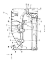
【選択図】図10
In a paper feed cassette, a slide member provided on a main body so as to be relatively movable is locked at a predetermined movement position. For this reason, when the slide member is moved from the main body to the moving position where a part of the leading end protrudes and locked in order to expand the paper placement space, an unexpected load in the main body direction is applied to the protrusion. In this case, there is a problem that an excessive force is applied to the lock member and the lock mechanism is damaged.
A slide member 119 provided on a cassette body 118 so as to be relatively movable, and a lock mechanism for locking the slide member at a predetermined position with respect to the cassette body in accordance with a sheet size. When a force is applied in the direction in which the slide member is accommodated with respect to the set body, the lock member (125, 126, 127) that moves in the direction in which the lock is released and the first in which the lock member is fitted And a locking groove 124a.
[Selection] Figure 10

Description

本発明は、画像形成装置に関し、特に装置本体に供給する記録用紙をあらかじめ収容するために用いられる給紙カセットに関する。   The present invention relates to an image forming apparatus, and more particularly to a paper feed cassette used for previously storing recording paper to be supplied to the apparatus main body.

従来、給紙カセットにおいて、カセット本体に相対移動可能に設けられたカセット延長部材は、所定の移動位置でロックされるようになっている(例えば、特許文献1参照)。   2. Description of the Related Art Conventionally, in a paper feed cassette, a cassette extension member provided on a cassette body so as to be relatively movable is locked at a predetermined movement position (see, for example, Patent Document 1).

特開平6―48590号公報(第3頁、図1)Japanese Patent Laid-Open No. 6-48590 (page 3, FIG. 1)

しかしながら、従来の給紙カセットにおいては、記録用紙の載置スペースを拡張するためにスライド部材であるカセット延長部材を、例えば給紙カセット本体からその先端方向の一部が突出する移動位置までスライド移動させてロックすると、この突出部が装置周辺の物体と接触して給紙カセット本体に納まる方向に力を受けた場合、ロック部材に過大な力が加わってロック機構が破損するという問題があった。   However, in the conventional paper feed cassette, the cassette extension member, which is a slide member, is slid and moved, for example, from the paper feed cassette body to a moving position where a part of the front end of the paper feed cassette protrudes in order to expand the recording paper placement space. When locked, if this projection comes in contact with an object around the device and receives a force in a direction that fits in the paper cassette body, there is a problem that an excessive force is applied to the lock member and the lock mechanism is damaged. .

本発明の給紙カセットは、媒体を収容する給紙カセットにおいて、
カセット本体と、前記カセット本体に相対移動可能に設けられたカセット延長部材と、用紙サイズに応じて、前記カセット本体に対して前記カセット延長部材を所定の位置でロックする位置固定機構とを有し、
前記位置固定機構は、前記カセット延長部材が前記カセット本体に対して収容される方向に力が加えられたとき、ロックが解除される方向に移動するロック部材と、前記ロック部材が嵌合する第1のロック溝とを有することを特徴とする。
The paper feed cassette of the present invention is a paper feed cassette for storing a medium.
A cassette body, a cassette extension member provided to be movable relative to the cassette body, and a position fixing mechanism that locks the cassette extension member at a predetermined position with respect to the cassette body according to a sheet size. ,
The position fixing mechanism includes a lock member that moves in a direction in which a lock is released when a force is applied in a direction in which the cassette extension member is accommodated with respect to the cassette body, and a first member that fits the lock member. And a single locking groove.

本発明による別の給紙カセットは、媒体を収容する給紙カセットにおいて、
カセット本体と、カセット本体に相対移動可能に設けられたカセット延長部材とを有し、
前記カセット延長部材は、前記媒体の、給紙方向の上流側の位置を規制する後端ガイド部材と、前記カセット本体によってガイドされる被ガイド部とを備え、
前記被ガイド部は、収容される前記媒体の載置面を形成する前記カセット本体の底面部でガイドされるように配設されることを特徴とする。
Another paper feed cassette according to the present invention is a paper feed cassette for accommodating a medium,
A cassette body, and a cassette extension member provided in the cassette body so as to be relatively movable,
The cassette extension member includes a rear end guide member that regulates the upstream position of the medium in the paper feeding direction, and a guided portion guided by the cassette body.
The guided portion is disposed so as to be guided by a bottom surface portion of the cassette body forming a placement surface for the medium to be accommodated.

本発明によれば、カセット延長部材が、カセット本体に対して引き出し位置にセットされた状態において、カセット延長部材をカセット本体に収容する方向の所定以上の力が加わった場合に、カセット延長部材が同方向に移動するため、カセット延長部材を収容する際の操作が簡単であり、また不慮の負荷がカセット延長部材に加わった場合にも構成部材の破損を防止することができる。   According to the present invention, in a state where the cassette extension member is set in the drawer position with respect to the cassette body, the cassette extension member is Since the cassette extension member is moved in the same direction, the operation for accommodating the cassette extension member is simple, and damage to the constituent members can be prevented even when an unexpected load is applied to the cassette extension member.

実施の形態1.
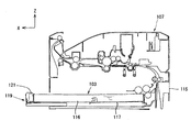
図1は、本発明による給紙カセットを採用した画像形成装置の実施の形態1の要部構成を概略的に示す要部構成図である。
Embodiment 1 FIG.
FIG. 1 is a main part configuration diagram schematically showing the main part configuration of Embodiment 1 of an image forming apparatus employing a paper feed cassette according to the present invention.

画像形成装置107は、外部のコンピュータ等から伝達されてきた画像データに基づき、電子写真方式により、記録用紙116上に画像を形成する。この画像形成装置107は、画像形成部101、給紙ユニット102、給紙カセット103、転写ローラ104、定着ユニット105、排紙ユニット106、及び印刷済の記録紙を載置する用紙積載部108を備えている。   The image forming apparatus 107 forms an image on the recording sheet 116 by electrophotography based on image data transmitted from an external computer or the like. The image forming apparatus 107 includes an image forming unit 101, a paper feeding unit 102, a paper feeding cassette 103, a transfer roller 104, a fixing unit 105, a paper discharging unit 106, and a paper stacking unit 108 on which printed recording paper is placed. I have.

画像形成部101は、イメージドラムカートリッジ109と光学ユニット113からなり、イメージドラムカートリッジ109は、像担持体としての感光体110、現像器111、及び帯電器112を保持している。感光体110の上部に配置されている光学ユニット113は、感光体110の軸線方向にLED素子が配列されているLEDヘッドある。また、光学ユニット113は、レーザ照射部とポリゴンミラーを備えたレーザスキャニングユニットを用いても良い。   The image forming unit 101 includes an image drum cartridge 109 and an optical unit 113, and the image drum cartridge 109 holds a photoconductor 110 as an image carrier, a developing device 111, and a charger 112. The optical unit 113 disposed on the top of the photoconductor 110 is an LED head in which LED elements are arranged in the axial direction of the photoconductor 110. The optical unit 113 may be a laser scanning unit including a laser irradiation unit and a polygon mirror.

図1中のX、Y、Zの各軸は、記録用紙116が画像形成部101を通過する際の搬送方向にX軸をとり、感光体110の回転軸方向にY軸をとり、これら両軸と直交する方向にZ軸をとっている。また、後述する他の図においてX、Y、Zの各軸が示される場合、これらの軸方向は、共通する方向を示すものとする。即ち、各図のXYZ軸は、各図の描写部分が、図1に示す画像形成装置101を構成する際の配置方向を示している。   The X, Y, and Z axes in FIG. 1 take the X axis in the transport direction when the recording paper 116 passes through the image forming unit 101, and take the Y axis in the rotational axis direction of the photoconductor 110. The Z axis is taken in a direction perpendicular to the axis. Moreover, when each axis | shaft of X, Y, and Z is shown in the other figure mentioned later, these axial directions shall show a common direction. That is, the XYZ axes in each drawing indicate the arrangement direction when the depicted portion of each drawing constitutes the image forming apparatus 101 shown in FIG.

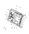
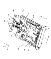
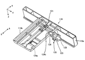
図2は、本発明による給紙カセット103の外観斜視図であり、図3は、その給紙カセット103の後述するカセット延長部材としてのスライド部材119を拡張した状態を示す外観斜視図である。   FIG. 2 is an external perspective view of the paper feed cassette 103 according to the present invention, and FIG. 3 is an external perspective view showing an expanded state of a slide member 119 as a cassette extension member described later of the paper feed cassette 103.

給紙カセット103は、図1に示すように画像形成装置107本体の下部に収容されるものであり、側面に設けられたガイド溝114を画像形成装置107の内部に備えられた図示しないレールに嵌合させ、図に示す矢印Aの方向に水平にスライドして挿入される。尚、上記したように、画像形成装置107の、給紙カセット103のように、着脱可能な或いは可動な構成要素の個々に対して、その構成要素を除いた部分を画像形成装置本体と称す。   As shown in FIG. 1, the paper feed cassette 103 is accommodated in the lower part of the main body of the image forming apparatus 107, and guide grooves 114 provided on the side surface are provided on a rail (not shown) provided inside the image forming apparatus 107. They are inserted and slid horizontally in the direction of arrow A shown in the figure. Note that, as described above, the portion of the image forming apparatus 107 excluding the detachable or movable components such as the paper feed cassette 103 is referred to as an image forming apparatus main body.

給紙カセット103の前面にはフロントカバー115が備えられ、このフロントカバー115が、図1に示すように画像形成装置107の前面下部のハウジングの一部を構成する。給紙カセット103は、上面が開口した平たい箱で構成され、その上面方向から記録用紙116(図1)を積載して収容する。フレームの内面に設けられた用紙積載台117に積載される記録用紙116は、図1に示すように給紙カセット103の前部上方に備えられる給紙ユニット102によって矢印B方向に供給される。このため、用紙積載台117は、積載した記録用紙116の最上紙が給紙ユニット102のピックアップローラ137に当接するように付勢する。   A front cover 115 is provided on the front surface of the paper feed cassette 103, and this front cover 115 constitutes a part of the housing at the lower front of the image forming apparatus 107 as shown in FIG. The paper feed cassette 103 is constituted by a flat box having an open top surface, and stores and accommodates recording paper 116 (FIG. 1) from the top surface direction. As shown in FIG. 1, the recording paper 116 stacked on the paper stacking base 117 provided on the inner surface of the frame is supplied in the direction of arrow B by the paper supply unit 102 provided above the front portion of the paper supply cassette 103. For this reason, the paper stacking table 117 biases the uppermost sheet of the stacked recording sheets 116 so as to contact the pickup roller 137 of the paper feeding unit 102.

スライド部材119は、カセット本体118に嵌合して記録用紙116の供給方向上流側を支持し、積載する記録用紙116のサイズに応じて記録用紙116の供給方向に移動可能である。尚、図3は、スライド部材119を矢印A方向に移動して記録用紙116の載置面積を拡張した給紙カセット103の拡張状態を示すものであるが、スライド部材119は、後述するように、この図3に示す位置を超えてカセット本体118から引き抜かれるようなことはない。そして、これらカセット本体118とスライド部材119とにはスライド部材119の移動をロックするロック機構120が傭えられている。   The slide member 119 is fitted to the cassette body 118 to support the upstream side in the supply direction of the recording paper 116 and is movable in the supply direction of the recording paper 116 according to the size of the recording paper 116 to be stacked. FIG. 3 shows the expanded state of the paper feed cassette 103 in which the slide member 119 is moved in the direction of arrow A to expand the loading area of the recording paper 116. The slide member 119 will be described later. The cassette body 118 is not pulled out beyond the position shown in FIG. The cassette body 118 and the slide member 119 are provided with a lock mechanism 120 that locks the movement of the slide member 119.

また、スライド部材119は、図3に示すように、用紙後端部をカバーするリヤカバー部119aと、リヤカバー部119aの略中央部から用紙供給方向に延在して用紙後端ガイド121をスライド可能に保持すると共に後述する第1と第2のロック溝124a,124b(図5)が形成された被カイド部119bを備えている。この被カイド部119bは、図2,3に示すように、カセット本体118の後側中央部に形成されたガイド凹部118aによって、記録用紙116の供給方向である同図中の矢印B及びその反対方向の矢印A方向にスライド可能に保持されている。また被カイド部119bの上面とガイド凹部118aが形成された部分のカセット本体118の底面とは略面一となっている。   Further, as shown in FIG. 3, the slide member 119 extends in the paper supply direction from a rear cover portion 119a that covers the rear end portion of the paper and a substantially central portion of the rear cover portion 119a, and can slide the paper rear end guide 121. And a to-be-guided portion 119b in which first and second lock grooves 124a and 124b (FIG. 5) described later are formed. As shown in FIGS. 2 and 3, the guide portion 119 b is formed by a guide recess 118 a formed in the rear center portion of the cassette body 118, and an arrow B in FIG. The direction of the arrow A is slidably held. Further, the upper surface of the to-be-guided portion 119b and the bottom surface of the cassette body 118 where the guide recess 118a is formed are substantially flush with each other.

このように給紙カセット103においては、カセット本体118の底面部118bと用紙積載台117とが、記録用紙116が載置される載置面を形成し、本実施の形態におけるスライド部材119は、カセット本体118の底面部118bに形成されたガイド凹部118aによって、被ガイド部119bのみがスライド可能に保持されるように構成されている。そしてこのガイド凹部118aは、図3に示すように、カセット本体118において、その後端部から用紙給紙方向(矢印B方向)に、且つこの用紙給紙方向に対する略幅中心振り分けに、即ち矢印A,B方向と直交する矢印C,D方向におけるカセット本体118の幅中心線160を略幅中心として形成されている。   Thus, in the paper feed cassette 103, the bottom surface portion 118b of the cassette body 118 and the paper stacking base 117 form a placement surface on which the recording paper 116 is placed, and the slide member 119 in the present embodiment is Only the guided portion 119b is slidably held by the guide recess 118a formed in the bottom surface portion 118b of the cassette body 118. As shown in FIG. 3, the guide recess 118a is arranged in the cassette main body 118 from the rear end thereof in the paper feeding direction (arrow B direction) and in a substantially centered width with respect to the paper feeding direction, that is, the arrow A , B in the direction of arrows C and D perpendicular to the direction B, the width center line 160 of the cassette body 118 is formed about the width center.

ここで例えば、スライド部材119が、カセット本体118と、カセット本体118の底面部及び用紙給紙方向に延在する両側部で重なるように構成されてガイドされる場合、スライド部材119を矢印A,B方向にスライドする際に擦れる箇所が多くなり、スライドしにくくなったり、負荷が大きい場合にはスライドできなくなるおそれが生じる。また、重なる部分が多いと給紙カセット全体の重量増加にもつながる。これらの点において、本実施の形態では、スライド部材119の被ガイド部119bのみが、カセット本体118によってスライド可能に保持された構成となっているため、スライド部材119をスライドする際の負荷の軽減、及び給紙カセット全体の軽量化に寄与することができる。   Here, for example, when the slide member 119 is configured and guided so as to overlap the cassette main body 118 and the bottom surface portion of the cassette main body 118 and both side portions extending in the paper feeding direction, the slide member 119 is indicated by the arrows A, When sliding in the B direction, there are many places that are rubbed, and it becomes difficult to slide, or if the load is large, there is a possibility that it cannot slide. In addition, if there are many overlapping parts, the weight of the entire sheet cassette will increase. In these respects, in the present embodiment, only the guided portion 119b of the slide member 119 is configured to be slidably held by the cassette body 118. Therefore, the load when sliding the slide member 119 is reduced. , And can contribute to the weight reduction of the entire sheet cassette.

用紙搬送方向上流側(矢印A方向)の端部をガイドする用紙後端ガイド121は、スライド部材119のスリット部122に嵌入してスライド可能に保持されている。従って、スライド部材119は、後述するように、図3に示す拡張状態、或いは図2に示す収容状態とされた後、用紙後端ガイド121によって積載される記録用紙の後端のガイド位置は調整可能としている。用紙後端ガイド121は、ロックレバー123によりスライド部材119本体に固定される。   A paper rear end guide 121 that guides an upstream end (direction of arrow A) in the paper transport direction is fitted into the slit portion 122 of the slide member 119 and is slidably held. Therefore, as described later, the slide member 119 is adjusted to the guide position of the rear end of the recording paper loaded by the paper rear end guide 121 after being in the expanded state shown in FIG. 3 or the accommodation state shown in FIG. It is possible. The sheet trailing edge guide 121 is fixed to the slide member 119 main body by a lock lever 123.

図4は、画像形成装置107が、スライド部材119が拡張状態の給紙カセット103を収容したときの態様を示す要部構成図である。同図に示すように、スライド部材119が拡張状態の給紙カセット103を画像形成装置107本体に収容した場合、スライド部材119は画像形成装置本体107からとび出している。   FIG. 4 is a main part configuration diagram illustrating a mode in which the image forming apparatus 107 accommodates the sheet feeding cassette 103 in which the slide member 119 is in the expanded state. As shown in the drawing, when the slide cassette 119 with the expanded sheet cassette 103 is accommodated in the image forming apparatus 107 main body, the slide member 119 protrudes from the image forming apparatus main body 107.

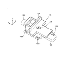
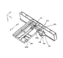
次に、給紙カセット103のロック機構120について、図5〜図7を参照しながら説明する。図5は、用紙後端ガイド121を保持するスライド部材119及びロック機構120を、上下逆にして斜めから見た外観斜視図であり、図6は、給紙カセット103を上下逆にして、カセット本体118及びスライド部材119に備えられたロック機構120の近傍を、正面から見た動作説明図であり、図7は、ロック機構120のスライドレバー125、アームレバー126及びスプリング128の外観斜視図である。尚、図6において、各部の配置を明確にするため、スライド部材119には左斜線を、ロック機構のスライドレバー125には右斜線を施している。   Next, the lock mechanism 120 of the paper feed cassette 103 will be described with reference to FIGS. FIG. 5 is an external perspective view of the slide member 119 and the lock mechanism 120 that hold the paper trailing edge guide 121 as viewed upside down, and FIG. 6 shows the cassette with the paper feed cassette 103 upside down. FIG. 7 is an operation explanatory view of the vicinity of the lock mechanism 120 provided in the main body 118 and the slide member 119 as viewed from the front, and FIG. 7 is an external perspective view of the slide lever 125, arm lever 126 and spring 128 of the lock mechanism 120. is there. In FIG. 6, in order to clarify the arrangement of each part, the slide member 119 is provided with a left oblique line, and the slide lever 125 of the lock mechanism is provided with a right oblique line.

図5に示すように、ロック機構120は、ロック溝124a,124b、スライドレバー125、アームレバー126、トーションスプリング127(図6)、及びスプリング128で構成されている。これらのうち、第1のロック溝124a及び第2のロック溝124bはスライド部材119に設けられ、他はカセット本体128に設けられる。スライド部材119に設けられたロック溝124a,124bは、記録用紙116の供給方向であってスライド部材119の移動方向に、位置をずらして設けられており、記録用紙116の供給方向(矢印B方向)下流側に第1のロック溝124aが、最上流側に第2のロック溝124bが設けられている。   As shown in FIG. 5, the lock mechanism 120 includes lock grooves 124 a and 124 b, a slide lever 125, an arm lever 126, a torsion spring 127 (FIG. 6), and a spring 128. Among these, the first lock groove 124 a and the second lock groove 124 b are provided in the slide member 119, and the others are provided in the cassette body 128. The lock grooves 124a and 124b provided in the slide member 119 are provided in a position shifted in the supply direction of the recording paper 116 and the movement direction of the slide member 119, and the supply direction of the recording paper 116 (the direction of arrow B) ) A first lock groove 124a is provided on the downstream side, and a second lock groove 124b is provided on the most upstream side.

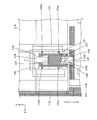
図5及び図6は、第2のロック溝124bにアームレバー126が嵌合している状態を示している。図5及び図6に示すように、スライドレバー125、アームレバー126、トーションスプリング127からなるロック部材、及びスプリング128は、カセット本体118に設けられたロック部材収納部146に収納され、このロック部材収納部146によってスライドレバー125が、スライド部材119の移動方向(矢印A、B方向)と直交する記録用紙116幅方向(Y軸方向)に移動可能に保持されている。即ちその4つの突起部125a〜125dが、カセット本体118に形成された図示しないガイドによって同方向にガイドされると共に、その移動範囲が規制されている。   5 and 6 show a state in which the arm lever 126 is fitted in the second lock groove 124b. As shown in FIGS. 5 and 6, the lock member including the slide lever 125, the arm lever 126, the torsion spring 127, and the spring 128 are accommodated in a lock member accommodating portion 146 provided in the cassette body 118. The slide lever 125 is held by the storage portion 146 so as to be movable in the width direction (Y-axis direction) of the recording paper 116 perpendicular to the moving direction (arrow A, B direction) of the slide member 119. That is, the four protrusions 125a to 125d are guided in the same direction by guides (not shown) formed in the cassette body 118, and the movement range is restricted.

アームレバー126は、図6に示すようにスライドレバー125に設けられた回動軸129を中心に回動できるように取付けられている。トーションスプリング127は、スライドレバー125の回動軸129に取付けられ、その一端側がアームレバー126に設けられた突起130に当接し、その他端側がスライドレバー125に設けられた受け孔131に嵌入している。これによりアームレバー126は、トーションスプリング127により常時矢印F方向に付勢されており、スライドレバー125のストッパ部132に突き当たっている。アームレバー126は、後述するように、所定のタイミングで第2のロック溝124b又は第1のロック溝124a(図5)と嵌合する。   As shown in FIG. 6, the arm lever 126 is attached so as to be rotatable around a rotation shaft 129 provided on the slide lever 125. The torsion spring 127 is attached to the rotation shaft 129 of the slide lever 125, one end of which is in contact with the protrusion 130 provided on the arm lever 126, and the other end is fitted into the receiving hole 131 provided on the slide lever 125. Yes. As a result, the arm lever 126 is always urged in the direction of arrow F by the torsion spring 127 and abuts against the stopper portion 132 of the slide lever 125. As will be described later, the arm lever 126 engages with the second lock groove 124b or the first lock groove 124a (FIG. 5) at a predetermined timing.

図2及び図7に示すように、スライドレバー125には、これを移動する時に指で操作する操作部133が設けられている。またスライドレバー125の一端には、スプリング128の端部を受ける受座であるピン134(図6)が、スライドレバー125の移動方向と平行に設けられ、スライドレバー125の上面には、ロック位置からロック解除位置に向かう方向を指す矢印135が一体成型されている。   As shown in FIGS. 2 and 7, the slide lever 125 is provided with an operation unit 133 that is operated by a finger when moving the slide lever 125. A pin 134 (FIG. 6), which is a receiving seat for receiving the end of the spring 128, is provided at one end of the slide lever 125 in parallel with the moving direction of the slide lever 125. An arrow 135 pointing in the direction from to the unlocking position is integrally molded.

図6に示すように、第1の付勢手段としてのスプリング128は、その一端がカセット本体118に設けられた受座であるピン136に、他端がスライドレバー125に設けられたピン134に圧縮した状態で挿入され、スライドレバー125を、用紙幅方向の外側から内側に向かう矢印D方向、すなわちロック位置へと向かう方向に付勢する。   As shown in FIG. 6, the spring 128 as the first urging means has one end on the pin 136 which is a seat provided on the cassette body 118 and the other end on the pin 134 provided on the slide lever 125. Inserted in a compressed state, the slide lever 125 is urged in an arrow D direction from the outer side to the inner side in the paper width direction, that is, a direction toward the lock position.

次に、画像形成装置全体の動作について説明する。
図1において、記録用紙116は、給紙ユニット102の、ピックアップローラ137により取り出され、給紙ローラ138により1枚ずつ用紙搬送方向下流へ送り出される。更に記録用紙116は、第1搬送ローラ139と第2搬送ローラ140により感光体110と転写ローラ104の圧接部へ搬送され、感光体110上に形成されたトナー像が転写される。その後、記録用紙116上の未定着トナーは、定着ユニット105において所定の温度となるように制御されたヒートローラ141と加圧ローラ142で熱圧着されることにより、記録用紙116上に定着される。そして記録用紙116は、第1排紙ローラ143と第2排紙ローラ144により、画像形成装置107の上面に形成された用紙積載部108に画像形成面を下にして排紙され、用紙116への画像形成が終了する。
Next, the operation of the entire image forming apparatus will be described.
In FIG. 1, the recording paper 116 is taken out by the pickup roller 137 of the paper supply unit 102 and is sent out one sheet at a time in the paper conveyance direction by the paper supply roller 138. Further, the recording paper 116 is conveyed to the pressure contact portion between the photosensitive member 110 and the transfer roller 104 by the first conveying roller 139 and the second conveying roller 140, and the toner image formed on the photosensitive member 110 is transferred. Thereafter, the unfixed toner on the recording paper 116 is fixed onto the recording paper 116 by being thermally pressed by the heat roller 141 and the pressure roller 142 that are controlled to have a predetermined temperature in the fixing unit 105. . The recording paper 116 is discharged by the first paper discharge roller 143 and the second paper discharge roller 144 onto the paper stacking unit 108 formed on the upper surface of the image forming apparatus 107 with the image forming surface facing down, and onto the paper 116. Image formation ends.

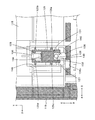
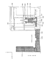
次に図2に示すように、スライド部材119がカセット本体118に収容されていて、図5及び図6に示すように、ロック部材のアームレバー126が第2のロック溝124bに嵌合してロックされている収容状態から、拡張されて図10に示すように、アームレバー126が第1のロック溝124aに嵌合してロックされる拡張状態へと移り変わる過程を、図6、図8〜図10を参照しながら説明する。   Next, as shown in FIG. 2, the slide member 119 is accommodated in the cassette body 118, and as shown in FIGS. 5 and 6, the arm lever 126 of the lock member is fitted into the second lock groove 124b. The process of changing from the locked housing state to the expanded state in which the arm lever 126 is fitted and locked in the first lock groove 124a as shown in FIG. This will be described with reference to FIG.

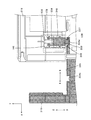
尚、図8〜図10は、図6と同様に、何れも給紙カセット103を上下逆にして、カセット本体118及びスライド部材119に備えられたロック機構120(図5)の近傍を、正面から見た動作説明図であり、各部の配置を明確にするため、スライド部材119には左斜線を、ロック機構のスライドレバー125には右斜線を施している。   8 to 10, as in FIG. 6, the sheet cassette 103 is turned upside down, and the vicinity of the lock mechanism 120 (FIG. 5) provided in the cassette body 118 and the slide member 119 is shown in front. In order to clarify the arrangement of each part, the slide member 119 is provided with a left oblique line, and the slide lever 125 of the lock mechanism is provided with a right oblique line.

例えば、カセット本体118にリーガル14(用紙幅215.9mm、用紙長さ355.6mm)の大きさの記録用紙116を収容する場合、スライド部材119を拡張する。このとき、スライド部材119が図2、図6に示す収容状態にあると、図6に示すように、アームレバー126が、第2のロック溝124bに嵌合し、更にスライドレバー125のストッパ部132につき当たっているため、スライド部材119をそのまま拡張方向(図6中の矢印Aの方向)へと移動することができない。尚、このように構成されているため、カセット本体118に記録用紙116を収納した状態でスライド部材119が不用意に拡張されることがないため、記録用紙116の搬送方向上流側の端部を所望の位置に確実に位置規制することができ、給紙不良を防ぐことができる。   For example, when the recording paper 116 having the size of legal 14 (paper width 215.9 mm, paper length 355.6 mm) is accommodated in the cassette body 118, the slide member 119 is expanded. At this time, when the slide member 119 is in the accommodated state shown in FIGS. 2 and 6, the arm lever 126 is fitted into the second lock groove 124b as shown in FIG. Since it hits 132, the slide member 119 cannot be moved in the expansion direction (direction of arrow A in FIG. 6) as it is. Since the slide member 119 is not inadvertently expanded in a state where the recording paper 116 is stored in the cassette body 118, the end of the upstream side in the transport direction of the recording paper 116 is provided. The position can be reliably restricted to a desired position, and a paper feed failure can be prevented.

従って、スライド部材119を拡張する場合には、使用者によって、スライドレバー125の操作部133(図7)に指を掛け、このスライドレバー125を、用紙幅方向外側(矢印C方向)、即ちスライドレバー125上に成型された矢印135(図7)に従って、スプリング128に抗して移動させる。これにより、図8に示すように、スライド部材119の第2のロック溝124bがアームレバー126の嵌合から解除されるので、拡張状態とするため、スライド部材119を矢印A方向に移動することが可能となる。   Therefore, when the slide member 119 is expanded, the user puts his / her finger on the operation portion 133 (FIG. 7) of the slide lever 125 and moves the slide lever 125 outside in the paper width direction (arrow C direction), that is, the slide. According to the arrow 135 (FIG. 7) molded on the lever 125, it is moved against the spring 128. As a result, as shown in FIG. 8, the second lock groove 124b of the slide member 119 is released from the fitting of the arm lever 126, so that the slide member 119 is moved in the direction of arrow A to bring it into an expanded state. Is possible.

このようにしてスライド部材119を拡張方向(図9の矢印A方向)へ約10mm移動した後、指をスライドレバー125の操作部133から離すと、スライドレバー125はスプリング134の作用により用紙幅方向内側、即ち矢印D方向に移動するが、このとき、図9に示すようにスライド部材119の第2のロック溝124bが既に移動しているため、アームレバー126は第2のロック溝124bに嵌入することなく、スライド部材119の壁145に当接する。このとき、アームレバー126は、トーションスプリング127に付勢されて、スライドレバー125のストッパ部132に当接した状態となっている。   After the slide member 119 is moved about 10 mm in the expansion direction (arrow A direction in FIG. 9) in this way, when the finger is released from the operation portion 133 of the slide lever 125, the slide lever 125 is moved in the paper width direction by the action of the spring 134. The arm lever 126 is inserted into the second lock groove 124b because the second lock groove 124b of the slide member 119 has already moved as shown in FIG. Without touching, it abuts against the wall 145 of the slide member 119. At this time, the arm lever 126 is biased by the torsion spring 127 and is in contact with the stopper portion 132 of the slide lever 125.

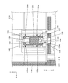
そして、第1のロック溝124aがアームレバー126の位置まで到達すると、図10に示すように、アームレバー126は、トーションスプリング127の作用によってスライドレバー125のストッパ部132に当接したまま、スプリング128の作用により第1のロック溝124aに嵌入して自動的にロック位置に移動する。従って、スライド部材119は、アームレバー126と第1のロック溝124aとが嵌合してロックされる拡張状態となる。   When the first lock groove 124a reaches the position of the arm lever 126, the arm lever 126 remains in contact with the stopper 132 of the slide lever 125 by the action of the torsion spring 127 as shown in FIG. By the action of 128, the first lock groove 124a is fitted and automatically moved to the lock position. Therefore, the slide member 119 is in an expanded state in which the arm lever 126 and the first lock groove 124a are fitted and locked.

次に、スライド部材119が、図10に示すように、カセット本体118から拡張した位置でロックされた拡張状態において、カセット本体118に収容される方向(図10中の矢印Bの方向)に力が加わった場合の動作について、図10〜図12を参照しながら説明する。   Next, as shown in FIG. 10, in the expanded state where the slide member 119 is locked at the position expanded from the cassette body 118, a force is applied in the direction in which the slide member 119 is accommodated in the cassette body 118 (the direction of arrow B in FIG. 10). The operation in the case of adding will be described with reference to FIGS.

このようにスライド部材119が拡張位置でロックされているとき、アームレバー126が第1のロック溝124aに嵌合し、更にアームレバー126がスライドレバー125のストッパ部132に突き当たっているため、スライド部材119は、更に拡張方向(図中矢印A方向)へと移動できないようになっている。   When the slide member 119 is locked in the extended position as described above, the arm lever 126 is fitted in the first lock groove 124a, and the arm lever 126 abuts against the stopper portion 132 of the slide lever 125. The member 119 cannot move further in the expansion direction (the direction of arrow A in the figure).

この拡張状態において、スライド部材119がカセット本体118に収容される方向(図中の矢印B方向)に力を加えられ、その力がトーションスプリング127の力より大きくなると、図11に示すように、第1のロック溝124aがアームレバー126に当接しながらこのアームレバー126をスライドレバー125の回動軸129を中心に反時計方向(図9の矢印Fの反対方向)に回動させる。アームレバー126が同方向に回動すると、やがてアームレバー126とスライド部材119の第1のロック溝124aとの嵌合状態が解除されるので、スライド部材119を収容方向である矢印B方向に移動することが可能となる。   In this expanded state, when a force is applied in the direction in which the slide member 119 is accommodated in the cassette body 118 (in the direction of arrow B in the figure) and the force is greater than the force of the torsion spring 127, as shown in FIG. While the first lock groove 124 a is in contact with the arm lever 126, the arm lever 126 is rotated in the counterclockwise direction (the direction opposite to the arrow F in FIG. 9) about the rotation shaft 129 of the slide lever 125. When the arm lever 126 rotates in the same direction, the fitting state between the arm lever 126 and the first lock groove 124a of the slide member 119 is eventually released, so that the slide member 119 is moved in the direction of arrow B which is the accommodation direction. It becomes possible to do.

このようにアームレバー126とスライド部材119の第1のロック溝124aとの嵌合状態が解除されてスライド部材119がカセット本体118に収容される方向に移動すると、アームレバー126は、図12に示すように、スライドレバー125のストッパ部132に当接する位置から所定角だけ回動して傾斜した状態において、トーションスプリング227の作用によりその先端部がスライド部材119の壁145に当接した状態を保つ。やがて、第2のロック溝124bがアームレバー126の先端部当接位置に到達すると、アームレバー126は、トーションスプリング127に付勢されてその先端部が第2のロック溝124bに入り込んで自動的にロック位置に移動する。従って、アームレバー126と第2のロック溝124bとが嵌合し、図6に示すように、スライド部材119がカセット本体118に収容されてロックされる収容状態となる。   Thus, when the fitting state of the arm lever 126 and the first lock groove 124a of the slide member 119 is released and the slide member 119 moves in the direction in which it is accommodated in the cassette body 118, the arm lever 126 is moved to FIG. As shown, in a state where the slide lever 125 is rotated by a predetermined angle from the position where it abuts against the stopper portion 132 and tilted, the tip portion of the slide lever 125 abuts against the wall 145 of the slide member 119. keep. Eventually, when the second lock groove 124b reaches the tip end contact position of the arm lever 126, the arm lever 126 is urged by the torsion spring 127, and the tip part enters the second lock groove 124b and automatically. Move to the locked position. Therefore, the arm lever 126 and the second lock groove 124b are fitted, and the slide member 119 is housed in the cassette body 118 and locked, as shown in FIG.

以上のように、本実施の形態の給紙カセットによれば、スライド部材119が装置周辺の物体と接触し、カセット本体118に収容される方向に所定以上の力が加えられたときに、アームレバー126がスライド部材119の第1のロック溝124aとの嵌合から外れるため、アームレバー126に過大な力が加わることがなく、アームレバー126、更にはスライドレバー125等のロック機構構成部材の破損を防ぐという効果が得られる。   As described above, according to the paper feed cassette of the present embodiment, when the slide member 119 comes into contact with an object around the apparatus and a force of a predetermined level or more is applied in the direction of being accommodated in the cassette body 118, the arm Since the lever 126 is disengaged from the fitting of the slide member 119 with the first lock groove 124a, an excessive force is not applied to the arm lever 126, and the arm lever 126, and further, the lock mechanism constituent members such as the slide lever 125, etc. The effect of preventing breakage is obtained.

また、スライド部材119をカセット本体118に収容する場合、スライド部材119を、トーションスプリング127の付勢力に抗して押すだけで、アームレバー126とスライド部材119の第1のロック溝124aとの嵌合状態を解除してこれを移動することができる。更に第2のロック溝124bがアームレバー126の位置に到達すると、アームレバー126と第2のロック溝124bとが自動的に勘合して、スライド部材119をロックするので、スライド部材119をカセット本体118に収容する際、スライドレバー125を用紙幅方向外側、更にはその逆方向へ操作する必要がないので、操作性がよく、便利である。   Further, when the slide member 119 is accommodated in the cassette body 118, the arm lever 126 and the first lock groove 124a of the slide member 119 are fitted to each other only by pushing the slide member 119 against the urging force of the torsion spring 127. The combined state can be canceled and moved. Further, when the second lock groove 124b reaches the position of the arm lever 126, the arm lever 126 and the second lock groove 124b automatically engage with each other to lock the slide member 119. Therefore, the slide member 119 is moved to the cassette body. When housed in 118, the slide lever 125 does not need to be operated outwardly in the paper width direction, or in the opposite direction, so that the operability is good and convenient.

実施の形態2.
図13は、本発明に基づく実施の形態2の給紙カセットに採用されるスライド部材219及びロック機構220を、上下逆にして斜めから見た外観斜視図であり、図14は、給紙カセットを上下逆にして、カセット本体218及びスライド部材219に備えられたロック機構220の近傍を、正面から見た動作説明図であり、図15は、ロック機構220のスライドレバー248の外観斜視図である。尚、図14において、各部の配置を明確にするため、スライド部材219には左斜線を、ロック機構のスライドレバー248には右斜線を施している。
Embodiment 2. FIG.
FIG. 13 is an external perspective view of the slide member 219 and the lock mechanism 220 employed in the paper feed cassette according to the second embodiment of the present invention as viewed from the obliquely upside down, and FIG. 14 is a paper feed cassette. Is an operation explanatory view of the vicinity of the lock mechanism 220 provided in the cassette body 218 and the slide member 219 as viewed from the front, and FIG. 15 is an external perspective view of the slide lever 248 of the lock mechanism 220. is there. In FIG. 14, the slide member 219 is provided with a left oblique line and the slide lever 248 of the lock mechanism is provided with a right oblique line in order to clarify the arrangement of each part.

図13に示すスライド部材219を採用する本実施の形態の給紙カセットが、前記した図5に示すスライド部材119を採用する実施の形態1の給紙カセット103(図2)と主に異なる点は、ロック機構220の構成である。従って、本実施の形態の給紙カセットが、前記した実施の形態1の給紙カセットと共通する部分には同符号を付して、或いは図面を省いて説明を省略し、異なる点を重点的に説明する。また、本実施の形態の画像形成装置の要部構成は、図1に示す実施の形態1の画像形成装置107の要部構成と共通するため、必要に応じて図1を参照する。   The paper feed cassette of this embodiment that employs the slide member 219 shown in FIG. 13 is mainly different from the paper feed cassette 103 (FIG. 2) of the first embodiment that employs the slide member 119 shown in FIG. These are the configurations of the lock mechanism 220. Accordingly, in the paper feeding cassette of the present embodiment, the same reference numerals are given to the parts common to the paper feeding cassette of the first embodiment described above, or the description is omitted by omitting the drawings, and different points are emphasized. Explained. Further, since the main configuration of the image forming apparatus according to the present embodiment is the same as the main configuration of the image forming apparatus 107 according to the first embodiment shown in FIG. 1, reference is made to FIG. 1 as necessary.

図13に示すように、ロック機構220は、ロック溝224a,224b、スライドレバー248、及びスプリング128で構成されている。これらのうち、第1のロック溝224a及び第2のロック溝224bはスライド部材219に設けられ、他はカセット本体218に設けられる。スライド部材219に設けられた第1と第2のロック溝224a,224bは、記録用紙116の供給方向であるスライド部材219の移動方向に、位置をずらして設けられており、記録用紙116の供給方向(矢印B方向)下流側に第1のロック溝224aが、最上流側に第2のロック溝224bが設けられている。   As shown in FIG. 13, the lock mechanism 220 includes lock grooves 224 a and 224 b, a slide lever 248, and a spring 128. Among these, the first lock groove 224 a and the second lock groove 224 b are provided in the slide member 219, and the others are provided in the cassette body 218. The first and second lock grooves 224 a and 224 b provided on the slide member 219 are provided with a position shifted in the moving direction of the slide member 219, which is the supply direction of the recording paper 116. A first lock groove 224a is provided downstream in the direction (arrow B direction), and a second lock groove 224b is provided on the most upstream side.

第1のロック溝224aには、後述するように、スライドレバー248と当接しながらこれを嵌合状態から嵌合解除方向に導くための斜面部249が設けられている。このため斜面部249は、スライド部材219の移動方向に対して垂直ではなく傾斜して形成されている。   As will be described later, the first lock groove 224a is provided with a sloped portion 249 for guiding the slide lever 248 from the fitted state to the fitted release direction while contacting the slide lever 248. Therefore, the slope portion 249 is formed to be inclined rather than perpendicular to the moving direction of the slide member 219.

図13及び図14は、スライド部材219がカセット本体218に収容されていて、第2のロック溝224bにスライドレバー248が嵌合してロックされる収容状態を示している。スライドレバー248は、カセット本体218内のロック部材収容部146で用紙116幅方向(Y軸方向)にスライド移動可能に保持され、第2のロック溝224bまたは第1のロック溝224aに嵌合する。スライドレバー248の突起部237の先端面には、斜面部250が設けられている。斜面部250は、その表面がスライドレバー248の移動方向に対して垂直ではなく傾斜した傾斜面となっている。   FIGS. 13 and 14 show a housed state in which the slide member 219 is housed in the cassette body 218 and the slide lever 248 is fitted and locked in the second lock groove 224b. The slide lever 248 is slidably held in the width direction (Y-axis direction) of the paper 116 by the lock member accommodating portion 146 in the cassette body 218, and is fitted into the second lock groove 224b or the first lock groove 224a. . A slope portion 250 is provided on the distal end surface of the protrusion 237 of the slide lever 248. The inclined surface 250 is an inclined surface whose surface is inclined rather than perpendicular to the moving direction of the slide lever 248.

図15に示すように、スライドレバー248には、これを移動する時に指で操作する操作部233が設けられている。スライドレバー248の一端には、スプリング128の端部を受ける受座であるピン234(図16)が設けられている。ピン234は、スライドレバー248の移動方向と平行に設けられ、スライドレバー248の上面には、ロック位置からロック解除位置に向かう方向を指す矢印235が一体成型されている。   As shown in FIG. 15, the slide lever 248 is provided with an operation unit 233 that is operated with a finger when moving the slide lever 248. One end of the slide lever 248 is provided with a pin 234 (FIG. 16) that is a seat for receiving the end of the spring 128. The pin 234 is provided in parallel with the moving direction of the slide lever 248, and an arrow 235 indicating a direction from the lock position to the lock release position is integrally formed on the upper surface of the slide lever 248.

図14に示すように、第1の付勢手段としてのスプリング128は、その一端がカセット本体218に設けられた受座であるピン136に、他端がスライドレバー248に設けられたピン234に圧縮した状態で挿入され、スライドレバー248を、用紙幅方向の外側から内側に向かう矢印D方向、すなわちロック位置へと向かう方向に付勢する。   As shown in FIG. 14, the spring 128 as the first urging means has one end on the pin 136 which is a seat provided on the cassette body 218 and the other end on the pin 234 provided on the slide lever 248. The slide lever 248 is inserted in a compressed state and biases the slide lever 248 in the arrow D direction from the outside to the inside in the sheet width direction, that is, the direction toward the lock position.

次に、ロック機構220の動作について説明する。
スライド部材219が、図14に示す収容状態にあると、スライドレバー248の突起部237が第2のロック溝224bに嵌合しているため、スライド部材219をそのまま拡張方向(図中矢印Aの方向)へと移動することができない。尚、このように構成されているため、カセット本体218に記録用紙116を収納した状態でスライド部材219が不用意に拡張されることがないため、記録用紙116の用紙搬送方向上流側の端部を所望の位置に確実に位置規制することができ、給紙不良を防ぐことができる。
Next, the operation of the lock mechanism 220 will be described.
When the slide member 219 is in the accommodated state shown in FIG. 14, since the projection 237 of the slide lever 248 is fitted in the second lock groove 224b, the slide member 219 is moved in the expansion direction (indicated by the arrow A in the figure). Direction). Since the slide member 219 is not inadvertently expanded in a state where the recording paper 116 is stored in the cassette body 218, the end portion of the recording paper 116 on the upstream side in the paper conveyance direction is configured. Can be reliably regulated at a desired position, and poor paper feeding can be prevented.

従って、スライド部材を拡張する場合には、使用者によって、スライドレバー248の操作部233(図15)に指を掛け、このスライドレバー248を、用紙幅方向外側(矢印C方向)、即ちスライドレバー248上に成型された矢印235(図15)に従って、スプリング128に抗して移動させる。これにより、スライド部材219の第2のロック溝224bがスライドレバー248の突起部237の嵌合から解除されるので、拡張状態とするため、スライド部材219を矢印A方向に移動することが可能となる。   Therefore, when expanding the slide member, the user puts his / her finger on the operation portion 233 (FIG. 15) of the slide lever 248, and the slide lever 248 is moved outward in the paper width direction (arrow C direction), that is, the slide lever. It is moved against the spring 128 according to the arrow 235 molded on 248 (FIG. 15). As a result, the second lock groove 224b of the slide member 219 is released from the fitting of the projection 237 of the slide lever 248, so that the slide member 219 can be moved in the direction of arrow A to bring it into an expanded state. Become.

このようにしてスライド部材219を拡張方向(図14の矢印A方向)へ約10mm移動した後、指をスライドレバー248の操作部233から離すと、スライドレバー248はスプリング134の作用により用紙幅方向内側、即ち矢印D方向に移動するが、このとき、すでにスライド部材219の第2のロック溝224bが移動しているため、スライドレバー248の突起部237は第2のロック溝224bに嵌入することなく、スライド部材219の壁245に当接する。   After the slide member 219 is moved about 10 mm in the expansion direction (arrow A direction in FIG. 14) in this way, when the finger is released from the operation portion 233 of the slide lever 248, the slide lever 248 is moved in the sheet width direction by the action of the spring 134. It moves inward, that is, in the direction of arrow D. At this time, since the second lock groove 224b of the slide member 219 has already moved, the protrusion 237 of the slide lever 248 is fitted into the second lock groove 224b. Instead, it abuts against the wall 245 of the slide member 219.

そして、第1のロック溝224aがスライドレバー248の位置まで到達すると、図16に示すように、スライドレバー248は、スプリング128の作用により、その突起部237が第1のロック溝224aに嵌入して自動的にロック位置に移動する。従って、スライド部材219は、スライドレバー248の突起部237と第1のロック溝224aとが嵌合してロックされる拡張状態となる。   When the first lock groove 224a reaches the position of the slide lever 248, as shown in FIG. 16, the protrusion 237 of the slide lever 248 is fitted into the first lock groove 224a by the action of the spring 128. Automatically move to the locked position. Therefore, the slide member 219 is in an expanded state in which the protrusion 237 of the slide lever 248 and the first lock groove 224a are fitted and locked.

次に、スライド部材219が、図16に示すように、カセット本体218から拡張した位置でロックされた状態において、カセット本体218に収容される方向(図16中の矢印Bの方向)に力か加わった場合の動作について、図16、図17を参照しながら説明する。   Next, when the slide member 219 is locked at a position expanded from the cassette body 218 as shown in FIG. 16, the force is applied in the direction in which the slide member 219 is accommodated in the cassette body 218 (the direction of arrow B in FIG. 16). The operation when added will be described with reference to FIGS. 16 and 17.

このようにスライド部材219が拡張位置でロックされているとき、スライドレバー248の突起部237が第1のロック溝224aに嵌合しているため、スライド部材219は、更に拡張方向(図中矢印A方向)へと移動できないようになっている。   Thus, when the slide member 219 is locked in the extended position, the protrusion 237 of the slide lever 248 is fitted in the first lock groove 224a, so that the slide member 219 is further extended in the extension direction (arrow in the figure). (A direction) cannot be moved.

この拡張状態において、スライド部材219がカセット本体218に収容される方向(図中の矢印B方向)に力を加えられると、図17に示すように、第1のロック溝224aの斜面部249が、スライドレバー248の突起部237の斜面部250に当接しながらスライドレバー248を、スプリング128に抗して用紙幅方向外側(矢印C方向)へ移動させる。スライドレバー248が同方向に移動すると、その突起部237とスライド部材219の第1のロック溝224aとの嵌合状態が解除されるので、スライド部材119を収容方向である矢印B方向に移動することが可能となる。   In this expanded state, when a force is applied in the direction in which the slide member 219 is accommodated in the cassette body 218 (the direction of arrow B in the figure), as shown in FIG. 17, the inclined surface portion 249 of the first lock groove 224a is The slide lever 248 is moved outwardly in the paper width direction (arrow C direction) against the spring 128 while abutting against the inclined surface portion 250 of the protrusion 237 of the slide lever 248. When the slide lever 248 moves in the same direction, the fitting state between the projection 237 and the first lock groove 224a of the slide member 219 is released, so that the slide member 119 is moved in the arrow B direction which is the accommodation direction. It becomes possible.

尚、スライドレバー248の突起部237の斜面部250は、ここでは、第1のロック溝224aの斜面部249と面接触するような傾斜面に形成したが、これに限定されるものではなく、例えば第1のロック溝224aの斜面部249と線接触するように断面円弧状の面としてもよい。   Here, the slope portion 250 of the protrusion 237 of the slide lever 248 is formed in an inclined surface that is in surface contact with the slope portion 249 of the first lock groove 224a, but is not limited thereto. For example, it may be a surface having an arcuate cross section so as to be in line contact with the slope portion 249 of the first lock groove 224a.

このようにスライドレバー248の突起部237とスライド部材219の第1のロック溝224aとの嵌合状態が解除されてスライド部材219がカセット本体218に収容される方向に移動すると、スライドレバー248の突起部237は、スプリング128の作用によりスライド部材219の壁245に当接した状態を保つ。やがて、第2のロック溝224bがスライドレバー248の突起部237の当接位置に到達すると、スライドレバー248は、スプリング128の作用により、その突起部237が第1のロック溝224に嵌入して自動的にロック位置に移動する。従って、スライドレバー248の突起部237と第2のロック溝224bとが嵌合し、図14に示すように、スライド部材219がカセット本体218に収容されてロックされる収容状態となる。   As described above, when the fitting state between the protrusion 237 of the slide lever 248 and the first lock groove 224a of the slide member 219 is released and the slide member 219 moves in a direction to be accommodated in the cassette body 218, the slide lever 248 The protrusion 237 maintains a state in which the protrusion 237 is in contact with the wall 245 of the slide member 219 by the action of the spring 128. Eventually, when the second lock groove 224b reaches the contact position of the protrusion 237 of the slide lever 248, the slide lever 248 is inserted into the first lock groove 224 by the action of the spring 128. It automatically moves to the locked position. Accordingly, the protrusion 237 of the slide lever 248 and the second lock groove 224b are fitted, and as shown in FIG. 14, the slide member 219 is housed in the cassette body 218 and locked.

ここで、図16に示すような、スライドレバー248の突起部237と第1のロック溝224aとが嵌合してロックした拡張状態において、スライド部材219に形成される第1のロック溝224aとスライドレバー248の突起部237との嵌合が解除されるために必要な、スライド部材219に加えられるカセット本体218に収容される方向(図16中の矢印Bの方向)の力と、スプリング128のテンションの関係について、図17を参照しながら説明する。   Here, in the expanded state in which the protrusion 237 of the slide lever 248 and the first lock groove 224a are fitted and locked as shown in FIG. 16, the first lock groove 224a formed in the slide member 219 and The force in the direction (in the direction of arrow B in FIG. 16) that is received in the cassette body 218 applied to the slide member 219 and the spring 128, which are necessary for releasing the fitting of the slide lever 248 with the protrusion 237. The tension relationship will be described with reference to FIG.

スライド部材219を収容方向へ押す力をF2、スライドレバー248の移動方向(矢印D方向)に対する第1のロック溝224aの斜面部249とスライドレバー248の突起部237の斜面部250の表面角度をθ、スライドレバー248の突起部237がスライド部材219の壁245に当接している時のスライドレバー248を付勢するスプリング128のテンションをF1とすると、スライド部材219に形成される第1のロック溝224aとスライドレバー248の突起部237との嵌合を解除するための条件式は、
F2>F1/tanθ
となる。
The force that pushes the slide member 219 in the accommodation direction is F 2 , and the surface angle of the slope portion 249 of the first lock groove 224a and the slope portion 250 of the projection portion 237 of the slide lever 248 with respect to the movement direction (arrow D direction) of the slide lever 248 the theta, the projections 237 of the slide lever 248 is a tension spring 128 for urging the slide lever 248 when in contact with the wall 245 of the slide member 219 and F 1, first formed in the slide member 219 1 The conditional expression for releasing the fitting between the lock groove 224a and the protrusion 237 of the slide lever 248 is
F 2 > F 1 / tan θ
It becomes.

例えば、F1が100gf、θ1が45°の場合、スライド部材219に形成される第1のロック溝224aとスライドレバー248の突起部237との嵌合を解除するためには、スライド部材219をF2=100gfより大きい値で収容方向へ押す必要がある。 For example, when F 1 is 100 gf and θ 1 is 45 °, the slide member 219 is used to release the fitting between the first lock groove 224a formed in the slide member 219 and the projection 237 of the slide lever 248. Must be pushed in the accommodating direction with a value greater than F 2 = 100 gf.

以上のように、本実施の形態の給紙カセットによれば、スライド部材219が装置周辺の物体と接触し、カセット本体218に収容される方向に所定以上の力が加えられたときに、スライドレバー248の突起部237がスライド部材219の第1のロック溝224aとの嵌合から外れるため、スライドレバー248に過大な力が加わることがなく、スライドレバー248等のロック機構構成部材の破損を防ぐという効果が得られる。   As described above, according to the paper feed cassette of the present embodiment, when the slide member 219 comes into contact with an object around the apparatus and a force of a predetermined level or more is applied in the direction in which the slide body 218 is accommodated, the slide Since the protrusion 237 of the lever 248 is disengaged from the fitting with the first lock groove 224a of the slide member 219, an excessive force is not applied to the slide lever 248, and the lock mechanism component such as the slide lever 248 is damaged. The effect of preventing is obtained.

また、スライド部材219をカセット本体218に収容する場合、スライド部材219をスプリング128の付勢力に抗して押すだけで、スライドレバー248の突起部237とスライド部材219の第1のロック溝224aとの嵌合状態を解除してこれを移動することができる。更に第2のロック溝224bがスライドレバー248の位置に到達すると、スライドレバー248の突起部237と第2のロック溝224bとが自動的に勘合して、スライド部材219をロックするので、スライド部材219をカセット本体218に収容する際、スライドレバー248を用紙幅方向外側、更にはその逆方向へ操作する必要がないので、操作性がよく、便利である。   Further, when the slide member 219 is accommodated in the cassette body 218, the projection 237 of the slide lever 248 and the first lock groove 224a of the slide member 219 can be obtained simply by pushing the slide member 219 against the biasing force of the spring 128. This can be moved by releasing the fitting state. Further, when the second lock groove 224b reaches the position of the slide lever 248, the projection 237 of the slide lever 248 and the second lock groove 224b are automatically fitted to lock the slide member 219, so that the slide member When the 219 is accommodated in the cassette body 218, it is not necessary to operate the slide lever 248 outward in the sheet width direction and further in the opposite direction, so that the operability is good and convenient.

更に、実施の形態1では、ロック部材をスライドレバー125、アームレバー126、及びトーションスプリング127で構成するが、本実施の形態では1つの部材であるスライドレバー248のみで構成できるため、構成を単純化でき、コスト面でも有利となる。   Furthermore, in the first embodiment, the lock member is configured by the slide lever 125, the arm lever 126, and the torsion spring 127. However, in this embodiment, the lock member can be configured by only one slide lever 248, and thus the configuration is simple. This is advantageous in terms of cost.

各実施の形態では、1つの画像形成部を備え、印刷媒体に直接トナー像を転写する画像形成装置を例にあげて説明したが、本発明はこれに限定されるものではなく、この例に限定されるものではなく、搬送される媒体に画像処理を行う装置、例えば中間転写ベルトを用いたカラー画像形成装置、複数のプロセスユニットを用いる複数色画像形成装置、それらを用いた複写機、自動原稿読み取り装置、インクジェットプリンタ、ドットプリンタ、複合機、媒体給送装置などにも適用可能である。   In each of the embodiments, an image forming apparatus that includes one image forming unit and directly transfers a toner image to a print medium has been described as an example. However, the present invention is not limited to this, and the present embodiment is not limited thereto. Without limitation, an apparatus for performing image processing on a conveyed medium, for example, a color image forming apparatus using an intermediate transfer belt, a multi-color image forming apparatus using a plurality of process units, a copying machine using them, an automatic The present invention can also be applied to a document reading device, an inkjet printer, a dot printer, a multi-function device, a medium feeding device, and the like.

本発明による給紙カセットを採用した画像形成装置の実施の形態1の要部構成を概略的に示す要部構成図である。1 is a main part configuration diagram schematically showing a main part configuration of a first embodiment of an image forming apparatus employing a paper feed cassette according to the present invention; 本発明による給紙カセットの外観斜視図である。1 is an external perspective view of a paper feed cassette according to the present invention. 本発明による給紙カセットの外観斜視図であり、スライド部材を拡張した状態を示す。It is an external appearance perspective view of the paper feed cassette by this invention, and shows the state which extended the slide member. 画像形成装置が、スライド部材が拡張状態の給紙カセットを収容したときの態様を示す要部構成図である。FIG. 3 is a main part configuration diagram showing a mode when the image forming apparatus accommodates a paper feeding cassette in which an extended state of a slide member. 実施の形態1において、用紙後端ガイドを保持するスライド部材及びロック機構を、上下逆にして斜めから見た外観斜視図である。In Embodiment 1, it is the external appearance perspective view which looked at the slide member and lock mechanism which hold | maintains a paper rear end guide upside down, and was seen from diagonally. 実施の形態1において、給紙カセットを上下逆にして、カセット本体及びスライド部材に備えられたロック機構の近傍を正面から見た動作説明図である。In Embodiment 1, it is operation | movement explanatory drawing which looked at the vicinity of the lock mechanism with which the sheet feeding cassette was turned upside down and was equipped with the cassette main body and the slide member from the front. 実施の形態1のロック機構のスライドレバー、アームレバー及びスプリングの外観斜視図である。FIG. 3 is an external perspective view of a slide lever, an arm lever, and a spring of the lock mechanism according to the first embodiment. 実施の形態1において、給紙カセットを上下逆にして、カセット本体及びスライド部材に備えられたロック機構の近傍を正面から見た動作説明図である。In Embodiment 1, it is operation | movement explanatory drawing which looked at the vicinity of the lock mechanism with which the sheet feeding cassette was turned upside down and was equipped with the cassette main body and the slide member from the front. 実施の形態1において、給紙カセットを上下逆にして、カセット本体及びスライド部材に備えられたロック機構の近傍を正面から見た動作説明図である。In Embodiment 1, it is operation | movement explanatory drawing which looked at the vicinity of the lock mechanism with which the sheet feeding cassette was turned upside down and was equipped with the cassette main body and the slide member from the front. 実施の形態1において、給紙カセットを上下逆にして、カセット本体及びスライド部材に備えられたロック機構の近傍を正面から見た動作説明図である。In Embodiment 1, it is operation | movement explanatory drawing which looked at the vicinity of the lock mechanism with which the sheet feeding cassette was turned upside down and was equipped with the cassette main body and the slide member from the front. 実施の形態1において、給紙カセットを上下逆にして、カセット本体及びスライド部材に備えられたロック機構の近傍を正面から見た動作説明図である。In Embodiment 1, it is operation | movement explanatory drawing which looked at the vicinity of the lock mechanism with which the sheet feeding cassette was turned upside down and was equipped with the cassette main body and the slide member from the front. 実施の形態1において、給紙カセットを上下逆にして、カセット本体及びスライド部材に備えられたロック機構の近傍を正面から見た動作説明図である。In Embodiment 1, it is operation | movement explanatory drawing which looked at the vicinity of the lock mechanism with which the sheet feeding cassette was turned upside down and was equipped with the cassette main body and the slide member from the front. 本発明に基づく実施の形態2において、給紙カセットに採用されるスライド部材及びロック機構を、上下逆にして斜めから見た外観斜視図である。In Embodiment 2 based on this invention, it is the external appearance perspective view which looked at the slide member and lock mechanism employ | adopted for a paper feeding cassette upside down, and was seen from diagonally. 実施の形態2において、給紙カセットを上下逆にして、カセット本体及びスライド部材に備えられたロック機構の近傍を正面から見た動作説明図である。In Embodiment 2, it is operation | movement explanatory drawing which looked at the vicinity of the lock mechanism with which the sheet feeding cassette was turned upside down and was equipped with the cassette main body and the slide member from the front. 実施の形態2のロック機構のスライドレバー及びスプリングの外観斜視図である。6 is an external perspective view of a slide lever and a spring of the lock mechanism of Embodiment 2. FIG. 実施の形態2において、給紙カセットを上下逆にして、カセット本体及びスライド部材に備えられたロック機構の近傍を正面から見た動作説明図である。In Embodiment 2, it is operation | movement explanatory drawing which looked at the vicinity of the lock mechanism with which the sheet feeding cassette was turned upside down and was equipped with the cassette main body and the slide member from the front. 実施の形態2において、スライド部材の第1のロック溝の斜面部の表面の角度θの説明に供する図である。In Embodiment 2, it is a figure where it uses for description of angle (theta) of the surface of the slope part of the 1st lock groove of a slide member.

符号の説明Explanation of symbols

101 画像形成部、 102 給紙ユニット、 103 給紙カセット、 104 転写ローラ、 105 定着ユニット、 106 排紙ユニット、 107 画像形成装置、 108 用紙積載部、 109 イメージドラムカートリッジ、 110 感光体、 111 現像器、 112 帯電器、 113 光学ユニット、 114 ガイド溝、 115 フロントカバー、 116 記録用紙、 117 用紙積載台、 118 カセット本体、 118a ガイド凹部、 118b 底面部、 119 スライド部材、 119a リヤカバー部、 119b 被ガイド部、 120 ロック機構、 121 用紙後端ガイド、 122 スリット部、 123 ロックレバー、 124a 第1のロック溝、 124b 第2のロック溝、 125 スライドレバー、 125a〜125d 突起部、 126 アームレバー、 127 トーションスプリング、 128 スプリング、 129 回動軸、 130 突起、 131 受け孔、 132 ストッパ部、 133 操作部、 134 ピン、 135 矢印、 136 ピン、 137 ピックアップローラ、 138 給紙ローラ、 139 第1搬送ローラ、 140 第2搬送ローラ、 141 ヒートローラ、 142 加圧ローラ、 143 第1排紙ローラ、 144 第2排紙ローラ、 145 壁、 146 ロック部材収容部、 218 カセット本体、 219 スライド部材、 220 ロック機構、 224a 第1のロック溝、 224b 第2のロック溝、 233 操作部、 234 ピン、 235 矢印、 237 突起部、 248 スライドレバー、 249,250 斜面部。   DESCRIPTION OF SYMBOLS 101 Image forming part, 102 Paper feed unit, 103 Paper feed cassette, 104 Transfer roller, 105 Fixing unit, 106 Paper discharge unit, 107 Image forming apparatus, 108 Paper stacking part, 109 Image drum cartridge, 110 Photoconductor, 111 Developer, 112 charger, 113 optical unit, 114 guide groove, 115 front cover, 116 recording paper, 117 paper stacking base, 118 cassette body, 118a guide recess, 118b bottom surface part, 119 slide member, 119a rear cover part, 119b guided part, 120 lock mechanism, 121 paper rear end guide, 122 slit portion, 123 lock lever, 124a first lock groove, 124b second lock groove, 125 slide lever, 125a to 125d Protrusion part, 126 Arm lever, 127 Torsion spring, 128 Spring, 129 Rotating shaft, 130 Protrusion, 131 Receiving hole, 132 Stopper part, 133 Operation part, 134 pin, 135 arrow, 136 pin, 137 Pickup roller, 138 paper feed roller, 139 first transport roller, 140 second transport roller, 141 heat roller, 142 pressure roller, 143 first paper discharge roller, 144 second paper discharge roller, 145 wall, 146 lock member housing, 218 Cassette body, 219 slide member, 220 lock mechanism, 224a first lock groove, 224b second lock groove, 233 operation section, 234 pin, 235 arrow, 237 projection, 248 slide lever , 249 and 250 slope portion.

Claims (12)

媒体を収容する給紙カセットにおいて、
カセット本体と、
前記カセット本体に相対移動可能に設けられたカセット延長部材と、
用紙サイズに応じて、前記カセット本体に対して前記カセット延長部材を所定の位置でロックする位置固定機構と
を有し、
前記位置固定機構は、
前記カセット延長部材が前記カセット本体に対して収容される方向に力が加えられたとき、ロックが解除される方向に移動するロック部材と、
前記ロック部材が嵌合する第1のロック溝と
を有することを特徴とする給紙カセット。
In a paper cassette that contains media,
The cassette body,
A cassette extension member provided in the cassette body so as to be relatively movable;
A position fixing mechanism for locking the cassette extension member at a predetermined position with respect to the cassette body according to the paper size;
The position fixing mechanism is
A lock member that moves in a direction in which the lock is released when a force is applied in a direction in which the cassette extension member is accommodated with respect to the cassette body;
And a first lock groove into which the lock member is fitted.
前記第1のロック溝を前記カセット延長部材に設け、前記ロック部材を前記カセット本体に前記カセット延長部材の移動方向と直交する方向に移動可能に設け、
前記ロック部材を前記カセット延長部材に向けて付勢する第1の付勢手段を備えたことを特徴とする請求項1記載の給紙カセット。
The first lock groove is provided in the cassette extension member, and the lock member is provided in the cassette body so as to be movable in a direction orthogonal to the moving direction of the cassette extension member,
2. The paper feed cassette according to claim 1, further comprising first biasing means for biasing the lock member toward the cassette extension member.
前記ロック部材は、
前記第1の付勢手段に付勢される第1のレバーと、
前記第1のロック溝に嵌合する第1の回動位置と、前記第1のロック溝との嵌合が解除される第2の回動位置との間で、前記第1のレバーに回動自在に保持される第2のレバーと、
前記第2のレバーを前記第1の回動位置に付勢する第2の付勢手段と
を備え、
前記カセット延長部材が前記カセット本体に対して収容される方向に力が加えられたとき、前記第2のレバーが前記第1の回動位置から前記第2の回動位置に向けて回動するように構成され、更に前記第1の回動位置から逆方向への回動が規制されていることを特徴とする請求項2記載の給紙カセット。
The locking member is
A first lever biased by the first biasing means;
The first lever is rotated between the first rotation position where the first lock groove is fitted and the second rotation position where the fitting with the first lock groove is released. A second lever movably held;
A second urging means for urging the second lever to the first rotation position;
When a force is applied in a direction in which the cassette extension member is accommodated with respect to the cassette body, the second lever rotates from the first rotation position toward the second rotation position. 3. The sheet feeding cassette according to claim 2, wherein the sheet feeding cassette is further configured to be restricted from turning in the reverse direction from the first turning position.
前記ロック部材は、前記第1のロック溝に嵌入可能な突起部を備え、
前記第1のロック溝に、前記カセット延長部材が前記カセット本体に対して収容される方向に加えられる力に応じて前記突起部を押圧する当接平面部を設け、該当接平面が、前記ロック部材を前記第1のロック溝から排出する方向の力が発生するように、前記ロック部材の移動方向に対して傾斜角θだけ傾斜していることを特徴とする請求項2記載の給紙カセット。
The lock member includes a protrusion that can be fitted into the first lock groove,
The first locking groove is provided with an abutting flat surface portion that presses the protrusion according to a force applied in a direction in which the cassette extension member is accommodated with respect to the cassette body, and the corresponding tangential plane is the lock 3. The sheet feeding cassette according to claim 2, wherein the sheet cassette is inclined by an inclination angle [theta] with respect to the moving direction of the lock member so as to generate a force in a direction in which the member is discharged from the first lock groove. .
前記突起部に前記当接平面部と面接触する平面部を設けたことを特徴とする請求項4記載の給紙カセット。   The sheet feeding cassette according to claim 4, wherein a planar portion that is in surface contact with the abutting planar portion is provided on the protrusion. 前記カセット延長部材が前記カセット本体に対して収容される方向に加えられる力をF2、前記第1の付勢部材による付勢力をF1とすると、ロックを解除するための条件が、
F2>F1/tanθ
であることを特徴とする請求項4又は5記載の給紙カセット。
When the force applied in the direction in which the cassette extension member is accommodated with respect to the cassette body is F 2 , and the urging force by the first urging member is F 1 , the condition for releasing the lock is:
F 2 > F 1 / tan θ
The paper feed cassette according to claim 4 or 5, wherein
前記カセット本体は、前記カセット延長部材を収容する位置で、前記ロック部材が嵌合する第2のロック溝を更に備えたことを特徴とする請求項2乃至6の何れかに記載の給紙カセット。   7. The paper feed cassette according to claim 2, wherein the cassette body further includes a second lock groove into which the lock member is fitted at a position where the cassette extension member is accommodated. . 前記ロック部材は、前記第1の付勢手段に抗して、前記第2のロック溝との嵌合を解除するための移動方向を示す印を備えたことを特徴とする請求項7記載の給紙カセット。   8. The lock member according to claim 7, further comprising a mark indicating a moving direction for releasing the fitting with the second lock groove against the first urging means. Paper cassette. 媒体を収容する給紙カセットにおいて、
カセット本体と、
カセット本体に相対移動可能に設けられたカセット延長部材と
を有し、
前記カセット延長部材は、
前記媒体の、給紙方向の上流側の位置を規制する後端ガイド部材と、
前記カセット本体によってガイドされる被ガイド部と
を備え、
前記被ガイド部は、収容される前記媒体の載置面を形成する前記カセット本体の底面部でガイドされるように配設されることを特徴とする給紙ガイド。
In a paper cassette that contains media,
The cassette body,
A cassette extension member provided in the cassette body so as to be relatively movable,
The cassette extension member is
A rear end guide member for regulating the upstream position of the medium in the paper feeding direction;
A guided portion guided by the cassette body,
The paper feed guide is characterized in that the guided portion is disposed so as to be guided by a bottom surface portion of the cassette body forming a placement surface of the medium to be accommodated.
前記被ガイド部が、前記カセット本体において、前記給紙方向に、且つ該給紙方向に対する略幅中心振り分けに形成されたガイド溝にガイドされて前記給紙方向に移動することを特徴とする請求項9記載の給紙カセット。   The guided portion is guided in a guide groove formed in the cassette main body in the paper feeding direction and substantially centered with respect to the paper feeding direction, and moves in the paper feeding direction. Item 10. The paper feed cassette according to Item 9. 前記後端ガイド部材は、前記給紙方向に移動可能に保持されていることを特徴とする請求項9又は10記載の給紙カセット。   11. The paper feed cassette according to claim 9, wherein the rear end guide member is held movably in the paper feed direction. 請求項1乃至11の何れかの給紙カセットを備えたことを特徴とする画像形成装置。   An image forming apparatus comprising the paper feed cassette according to claim 1.
JP2008033912A 2008-02-15 2008-02-15 Paper feed cassette and image forming apparatus Withdrawn JP2009190842A (en)

Priority Applications (2)

Application Number Priority Date Filing Date Title
JP2008033912A JP2009190842A (en) 2008-02-15 2008-02-15 Paper feed cassette and image forming apparatus
US12/320,482 US8573588B2 (en) 2008-02-15 2009-01-27 Medium feeding cassette and image forming apparatus

Applications Claiming Priority (1)

Application Number Priority Date Filing Date Title
JP2008033912A JP2009190842A (en) 2008-02-15 2008-02-15 Paper feed cassette and image forming apparatus

Publications (1)

Publication Number Publication Date
JP2009190842A true JP2009190842A (en) 2009-08-27

Family

ID=40954377

Family Applications (1)

Application Number Title Priority Date Filing Date
JP2008033912A Withdrawn JP2009190842A (en) 2008-02-15 2008-02-15 Paper feed cassette and image forming apparatus

Country Status (2)

Country Link
US (1) US8573588B2 (en)
JP (1) JP2009190842A (en)

Families Citing this family (6)

* Cited by examiner, † Cited by third party
Publication number Priority date Publication date Assignee Title
US7922171B2 (en) * 2007-01-31 2011-04-12 Canon Kabushiki Kaisha Sheet feeding device and image forming apparatus
JP4814927B2 (en) * 2008-10-17 2011-11-16 株式会社沖データ Sheet deposition apparatus and image forming apparatus
JP5312131B2 (en) * 2009-03-24 2013-10-09 キヤノン株式会社 Slide unit moving device and image forming apparatus
JP5759272B2 (en) * 2011-06-03 2015-08-05 株式会社沖データ Medium cassette and image forming apparatus
CN203246908U (en) 2013-04-16 2013-10-23 深圳迈瑞生物医疗电子股份有限公司 Paper bin structure and electrocardiogram machine
JP7066102B2 (en) * 2017-11-24 2022-05-13 株式会社リコー Sheet loading device and image forming device

Family Cites Families (8)

* Cited by examiner, † Cited by third party
Publication number Priority date Publication date Assignee Title
JPH0551136A (en) * 1991-08-22 1993-03-02 Brother Ind Ltd Paper feed cassette device in image forming device
JP2840517B2 (en) * 1992-06-02 1998-12-24 キヤノン株式会社 Paper cassette and image forming apparatus
JPH0648590A (en) 1992-07-28 1994-02-22 Nec Corp Paper cassette for printer
JP3676895B2 (en) * 1996-10-15 2005-07-27 パナソニック コミュニケーションズ株式会社 Paper cassette
JP2006137548A (en) * 2004-11-12 2006-06-01 Canon Inc Sheet stacking apparatus and recording apparatus
US7607657B2 (en) * 2006-09-29 2009-10-27 Canon Kabushiki Kaisha Sheet feeding apparatus and image forming apparatus
US7922171B2 (en) * 2007-01-31 2011-04-12 Canon Kabushiki Kaisha Sheet feeding device and image forming apparatus
US8002270B2 (en) * 2008-05-29 2011-08-23 Lexmark International, Inc. Media tray with media restraint assembly adjustable between and lockable at multiple closely spaced positions

Also Published As

Publication number Publication date
US8573588B2 (en) 2013-11-05
US20090206545A1 (en) 2009-08-20

Similar Documents

Publication Publication Date Title
JP5014451B2 (en) Medium loading apparatus and image forming apparatus
CN100576095C (en) imaging device
JP5613650B2 (en) Medium conveying apparatus and image forming apparatus
US8366098B2 (en) Medium storage device, image forming device and medium storage system
JP4429952B2 (en) Image forming apparatus
JP5649561B2 (en) Medium loading apparatus and image forming apparatus
JP3960322B2 (en) Recording sheet supply apparatus and facsimile apparatus
US8573588B2 (en) Medium feeding cassette and image forming apparatus
JP2018108873A (en) Conveying apparatus, medium discharging apparatus, and image forming apparatus
JP7731019B2 (en) Image forming device
US8746683B2 (en) Sheet feeder and image forming apparatus
JP2007096889A (en) Image processing device
JP2024097585A (en) SHEET FEEDING DEVICE, IMAGE READING DEVICE, AND IMAGE FORMING APPARATUS
JP5110365B2 (en) Image recording medium supply apparatus and image forming apparatus
JP2008254842A (en) Image forming apparatus
JP2009053315A (en) Image forming apparatus
JP6319978B2 (en) Sheet feeding apparatus and image forming apparatus
JP2007119198A (en) Image forming device
JP6733011B2 (en) Sheet feeding apparatus and image forming apparatus
JP7363276B2 (en) Media transport device
JP6545313B2 (en) Sheet feeding apparatus and image forming apparatus
JP5100558B2 (en) Sheet feeding apparatus and image forming apparatus
JP3761989B2 (en) Sheet stacking apparatus and image forming apparatus
JP2010076930A (en) Sheet storage device and image recording device
JP2000072260A (en) Image forming device

Legal Events

Date Code Title Description
A300 Application deemed to be withdrawn because no request for examination was validly filed

Free format text: JAPANESE INTERMEDIATE CODE: A300

Effective date: 20110510