JP2009200410A - Vacuum processor - Google Patents
Vacuum processor Download PDFInfo
- Publication number
- JP2009200410A JP2009200410A JP2008042957A JP2008042957A JP2009200410A JP 2009200410 A JP2009200410 A JP 2009200410A JP 2008042957 A JP2008042957 A JP 2008042957A JP 2008042957 A JP2008042957 A JP 2008042957A JP 2009200410 A JP2009200410 A JP 2009200410A
- Authority
- JP
- Japan
- Prior art keywords
- processing chamber
- sample
- processing apparatus
- vacuum
- plates
- Prior art date
- Legal status (The legal status is an assumption and is not a legal conclusion. Google has not performed a legal analysis and makes no representation as to the accuracy of the status listed.)
- Granted
Links
Images





Landscapes
- Drying Of Semiconductors (AREA)
Abstract
【課題】ターボ分子ポンプから跳ね返った異物の進行をより効果的に抑制し、試料の歩留まりを低下させず、且つ、清掃が容易な構造を備えた真空処理装置を提供する。
【解決手段】真空容器11内に配置され内部でプラズマが形成される処理室20と、この処理室20内の下部に配置されその上面に処理対象の試料Wが載置される試料台19と、前記処理室20の上方に配置されこの処理室内に処理用のガスを導入するための導入孔を有するガス導入機構13と、前記処理室内の下部に配置される処理室内の圧力を制御する圧力制御機構24と、処理室内を排気するためのターボ分子ポンプ25を有し、試料台19の下部に前記ターボ分子ポンプ25が設置された同軸の排気構造を有する真空処理装置において、前記処理室20内壁面と試料台19の外周側壁面との間に形成される排気経路に、2つ以上の板31,32を互い違いに設置した。
【選択図】 図1The present invention provides a vacuum processing apparatus that has a structure that can more effectively suppress the progress of foreign matter bounced off from a turbo molecular pump, does not reduce the yield of a sample, and is easy to clean.
A processing chamber 20 disposed in a vacuum vessel 11 and generating plasma therein, and a sample stage 19 disposed in a lower portion of the processing chamber 20 on which a sample W to be processed is placed. A gas introduction mechanism 13 disposed above the processing chamber 20 and having an introduction hole for introducing a processing gas into the processing chamber, and a pressure for controlling the pressure in the processing chamber disposed in the lower portion of the processing chamber In the vacuum processing apparatus having a coaxial exhaust structure in which a control mechanism 24 and a turbo molecular pump 25 for evacuating the processing chamber are provided, and the turbo molecular pump 25 is installed below the sample stage 19, the processing chamber 20 Two or more plates 31 and 32 were alternately installed in the exhaust path formed between the inner wall surface and the outer peripheral side wall surface of the sample stage 19.
[Selection] Figure 1
Description
本発明は、ガス導入機構とガス排気機構が設置された内部にプラズマを形成する処理室が設けられた真空容器と、この処理室内の下部に配置された試料を設置する試料台を有し、その試料台の下部に試料台と平行にターボ分子ポンプが設置された真空処理装置であって、前記真空容器と前記試料台と前記ターボ分子ポンプが同軸に配置された排気構造を備えており、特にターボ分子ポンプの回転翼に衝突し跳ね返った異物が試料へ付着することを抑制する機構を有する真空処理装置に関する。 The present invention has a vacuum vessel provided with a processing chamber for forming plasma inside a gas introduction mechanism and a gas exhaust mechanism, and a sample stage for installing a sample disposed in the lower part of the processing chamber, A vacuum processing apparatus in which a turbo molecular pump is installed in parallel with the sample stage at the bottom of the sample stage, and includes an exhaust structure in which the vacuum vessel, the sample stage, and the turbo molecular pump are arranged coaxially, In particular, the present invention relates to a vacuum processing apparatus having a mechanism for suppressing foreign matter that has collided and bounced off a rotor blade of a turbo molecular pump from adhering to a sample.
近年の半導体デバイス製造工程においては、デバイスの高集積化に伴う歩留まりの向上対策の要求が年々厳しくなっている。具体的には、例えば試料面内における加工寸法差を低減させる要求、異物粒径および個数の許容値に関する要求がある。例えば、試料面内の加工寸法差の低減としては、排気装置が偏って設けられることによる排気方向への偏りによる加工寸法差の増加等への対応が考えられる。このような排気方向の偏りによる加工寸法差の増加に対応する半導体装置のプラズマ処理装置(真空処理装置)として、試料台と排気機構(ターボ分子ポンプ)を上下方向に重ねて平行に設置し、真空処理室と試料台と排気機構を同軸に配置して、真空処理室内壁と試料台の間に排気経路を形成し、被処理物の周辺から排気して排気の偏りをなくした排気構造が有効であることが知られている。 In recent semiconductor device manufacturing processes, demands for measures for improving yields due to high integration of devices are becoming stricter year by year. Specifically, for example, there is a request for reducing a processing dimensional difference in the sample surface, and a request for an allowable value of the particle size and number of foreign matters. For example, as a reduction in the processing dimensional difference in the sample surface, it is conceivable to cope with an increase in the processing dimensional difference due to the deviation in the exhaust direction due to the evacuation device being provided unevenly. As a plasma processing apparatus (vacuum processing apparatus) of a semiconductor device corresponding to an increase in processing dimension difference due to such a deviation in the exhaust direction, a sample stage and an exhaust mechanism (turbo molecular pump) are installed in parallel in the vertical direction, The vacuum processing chamber, the sample stage, and the exhaust mechanism are arranged coaxially, and an exhaust path is formed between the vacuum processing chamber wall and the sample stage. It is known to be effective.
このような真空処理装置における異物の発生源は、例えばドライエッチングにおいては、エッチング処理中に発生した反応生成物および配線加工形状制御のために用いられるデポジション効果の高いガスが処理室内壁に付着し、その付着物は処理室内の可動部位の可動、処理室内のガスフラックス、プラズマの作用および処理室内の温度変化等により剥がれ落ち異物となる。これらの異物低減策としては、定期交換が可能な構造とし、容易で定期的な清掃や交換を可能としたり、反応生成物等が付着或いは堆積し難い構造、例えば、表面温度の上昇、部位部材の選択等の工夫が実施されていた。しかし、これらの異物低減策によっても、処理室への反応生成物等の付着を完全に無くすことは困難であり、特に清掃がし難い部位や、交換ができない部位、可動部位、および処理室の下部に設置されている排気機構の周辺への反応生成物等の付着が存在し、異物を発生させる原因となっていた。 The source of foreign matter in such a vacuum processing apparatus is, for example, in dry etching, a reaction product generated during the etching process and a gas with a high deposition effect used for controlling the wiring processing shape adhere to the inner wall of the processing chamber. The deposits are peeled off and become foreign substances due to the movement of the movable part in the processing chamber, the gas flux in the processing chamber, the action of plasma, the temperature change in the processing chamber, and the like. These foreign matter reduction measures include a structure that can be periodically replaced, and can be easily and periodically cleaned and replaced, or a structure in which reaction products or the like are difficult to adhere or accumulate, such as an increase in surface temperature, a part member Ingenuity such as selection of was carried out. However, even with these foreign matter reduction measures, it is difficult to completely eliminate the adhesion of reaction products and the like to the processing chamber. Particularly, it is difficult to clean, replaceable, movable, and processing chambers. Adhesion of reaction products or the like to the periphery of the exhaust mechanism installed in the lower part is present, causing foreign matter to be generated.
真空処理装置で発生した異物の殆どは、ターボ分子ポンプおよびドライポンプによりエッチングガスと共に排気されるが、上述のような同軸構造を有する真空処理装置においては、ターボ分子ポンプ内にある回転翼に衝突した異物の一部は排気されず、エネルギーを得ることで処理室上部へ逆流する場合がある。これは、ターボ分子ポンプから大きなエネルギーを得ているため、排気流に係らず容易に逆流することができるからである。これらの異物は、処理室内壁への衝突を繰り返し処理室上部へ逆流し、一部は試料に入射することで配線加工に影響を及ぼすことになる。デバイス構造の高度化が進むことで異物の許容粒径が小さくなり許容個数も厳しくなると、この処理室下部から逆流してくる異物をも抑制しないと歩留まりが低下し生産に支障が発生する状況となってきた。さらに、このような異物は突発的に増加する異物の要因ともなっていた。 Most of the foreign matter generated in the vacuum processing apparatus is exhausted together with the etching gas by the turbo molecular pump and the dry pump. However, in the vacuum processing apparatus having the coaxial structure as described above, it collides with the rotor blade in the turbo molecular pump. A part of the foreign matter is not exhausted and may flow backward to the upper part of the processing chamber by obtaining energy. This is because a large amount of energy is obtained from the turbo molecular pump, so that the reverse flow can be easily performed regardless of the exhaust flow. These foreign substances repeatedly collide with the inner wall of the processing chamber and flow back to the upper portion of the processing chamber, and a part of the foreign matter enters the sample, thereby affecting the wiring processing. As the device structure becomes more sophisticated, the allowable particle size of foreign objects becomes smaller and the allowable number becomes stricter.If foreign materials flowing back from the lower part of the processing chamber are not suppressed, the yield will decrease and production will be hindered. It has become. Further, such foreign matter has been a cause of sudden increase in foreign matter.
このようなターボ分子ポンプを用いた真空処理装置における異物の逆流の対策手段として、排気経路に反射板を設置し、その反射板の形状により試料への異物数を低減する技術が提案されている(例えば、特許文献1参照)。また、排気経路にターボ分子ポンプを用いた排気系が提案されている(例えば、特許文献2参照)。
しかしながら、上記従来技術では、異物の低減に関して、複雑な構造物を設置し異物の進行を抑制しようとしているが、単一構造であり異物進行の抑制が不十分であり、且つ、構造が複雑であり洗浄のし易さまでも考慮されていなかった。本発明の目的は、排気経路に複雑な構造物を有しない2つ以上の板を互い違いに設置することにより、ターボ分子ポンプから跳ね返った異物の進行をより効果的に抑制し、試料の歩留まりを低下させず、且つ、清掃が容易な構造を備えた真空処理装置を提供することにある。 However, in the above prior art, regarding the reduction of the foreign matter, a complicated structure is installed to suppress the progress of the foreign matter, but the single structure is insufficient to suppress the foreign matter progression, and the structure is complicated. There was no consideration for ease of cleaning. The object of the present invention is to provide two or more plates that do not have a complicated structure in the exhaust path in a staggered manner, thereby more effectively suppressing the progress of foreign matter bounced off from the turbo molecular pump, and reducing the sample yield. An object of the present invention is to provide a vacuum processing apparatus having a structure that does not decrease and is easy to clean.
上記課題を解決するために、本発明は、真空容器内に配置され内部でプラズマが形成される処理室と、この処理室内の下部に配置されその上面に処理対象の試料が載置される試料台と、前記処理室の上方に配置されこの処理室内に処理用のガスを導入するための導入孔を有するガス導入機構と、前記処理室内の下部に配置される処理室内の圧力を制御する圧力制御機構と、処理室内を高真空で保持するためのターボ分子ポンプを有し、試料台の下部に前記ターボ分子ポンプが平行に設置された同軸構造の排気構造真空処理装置において、前記処理室内壁面と試料台の外周側壁面との間に形成される排気経路に2つ以上の板を平行、且つ、互い違いに設置した構造を具備することにより達成される。 In order to solve the above-described problems, the present invention provides a processing chamber in which a plasma is formed inside a vacuum vessel, and a sample in which a sample to be processed is placed on the upper surface of the processing chamber. A base, a gas introduction mechanism disposed above the processing chamber and having an introduction hole for introducing processing gas into the processing chamber, and a pressure for controlling the pressure in the processing chamber disposed at a lower portion of the processing chamber In a vacuum processing apparatus having a coaxial structure and having a control mechanism and a turbo molecular pump for holding the processing chamber at a high vacuum in a high vacuum, the turbo molecular pump is installed in parallel at the lower part of a sample stage. This is achieved by providing a structure in which two or more plates are arranged in parallel and staggered in the exhaust path formed between the sample table and the outer peripheral side wall surface of the sample stage.
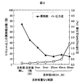
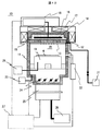
本発明の実施例について、図を用い以下に説明する。図1は本発明にかかるプラズマ処理装置の処理室の構成を説明する縦断面図である。図2は本発明のプラズマ処理装置を用いた実験1における2枚の反射板の重なり範囲と異物数の関係および反射板の重なりの範囲と圧力差の関係を説明する図である。図3は本発明のプラズマ処理装置を用いた実験1における試料上の圧力測定方法説明する図である。図4は本発明のプラズマ処理装置を用いた実験2にかかる異物源の貼り付け位置を説明する図である。図5は本発明のプラズマ処理装置を用いた実験2における異物源の貼り付け位置を変えた場合の反射板有無による異物数の関係を説明する図である。図6は本発明のプラズマ処理装置を用いた実験3にかかる2枚の反射板の重なり範囲を5mmとした場合の2枚の反射板の設置間隔と異物数および圧力差の関係を説明する図である。図7は本発明のプラズマ処理装置を用いた実験3にかかる2枚の反射板の重なりを40mmとした場合の2枚の反射板の設置間隔と異物数および圧力差の関係を説明する図である。図8は本発明のプラズマ処理装置を用いた実験4にかかる反射板の有無と放電異物数の関係を説明する図表である。図9は試料台とターボ分子ポンプを同軸に配置したプラズマ処理装置の装置構成を説明する平面図であり、図10は図9に示したプラズマ処理装置の一つの処理装置の構成を示す縦断面図である。図11は異物測定手順の例を説明するステップ図であり、図12は異物発生の切り分け結果の例を示す図表であり、図13は搬送動作での試料に付着する異物数の測定手順の例を説明するステップ図である。
Embodiments of the present invention will be described below with reference to the drawings. FIG. 1 is a longitudinal sectional view for explaining the configuration of a processing chamber of a plasma processing apparatus according to the present invention. FIG. 2 is a diagram for explaining the relationship between the overlapping range of the two reflecting plates and the number of foreign substances and the relationship between the overlapping range of the reflecting plates and the pressure difference in Experiment 1 using the plasma processing apparatus of the present invention. FIG. 3 is a diagram for explaining a method for measuring pressure on a sample in Experiment 1 using the plasma processing apparatus of the present invention. FIG. 4 is a view for explaining the position where the foreign material source is applied in
図9を用いて本発明の前提となるプラズマ処理装置全体の構成を説明する。プラズマ処理装置100は、大気ブロック101と真空ブロック102の2つより構成されている。大気ブロック101は、大気搬送ロボットを備えた大気搬送容器107および半導体素子基板等の試料が収納された複数のカセットを設置するカセット設置台108を備えている。真空ブロック102は、内部に真空搬送ロボットを有し、室内の減圧および不活性ガスであるアルゴンガスが導入されている真空搬送容器105と、この真空搬送容器105と大気ブロック101を接続する複数のロック室106と、減圧された内部に試料を搬入しエッチング処理を行う複数の真空容器103、および、減圧された内部に試料を搬入しアッシング(灰化)処理を行う複数の真空容器104を備えている。真空容器103と真空搬送容器105の間には容器間が遮断できるようにゲートバルブが設置されている。
The overall configuration of the plasma processing apparatus as a premise of the present invention will be described with reference to FIG. The
図10を用いて図9に示したプラズマ処理装置100を構成する真空容器103の処理室10の構成を説明する。処理室10は、処理容器11と処理容器11の上部を形成する蓋部材12にて構成される処理室内20がある。蓋部材12の上部にはアンテナ部材が設置されており、このアンテナ部材はSUS等の導電性部材で構成された蓋部材16と、その内側に設置された平板形状のアンテナ14と、アンテナ14と蓋部材16との間に配置されてこれらの間を絶縁すると共に、アンテナ14から放出される電波を処理室内20に伝播させるために配置されたリング形状を備えた少なくとも1つの誘電体15から構成されている。前記アンテナ14は、同軸ケーブル等によりUHF帯の電波を形成する電波源18に接続されており、伝達してきた電波はアンテナ14を介して、処理室内20に電波が導入される。処理室10の上部周囲には、ソレノイドコイル17が配置され、それにより生成された磁界が処理室内20に供給される。蓋部材12の下にはプロセスガスが通るための複数の孔があけられたシャワープレート13が設置されており、マスフローコントローラ21で流量調整されたプロセスガスは、蓋部材12とシャワープレート13の隙間を通りシャワープレート13にあけられた複数の孔より処理室内20へと供給される。試料台19より上方の処理室内20の空間には、シャワープレート13の複数の穴から供給されたプロセスガスと、蓋部材12を介して導入された電波と、ソレノイドコイル17から生成された磁場との相互作用によりプラズマが生成される。試料台19に設置された試料Wは、生成されたプラズマと試料台19下部に設置された高周波電源26により異方性のエッチングが進行する。
The configuration of the
また、処理室内20は処理室下部に設置されたターボ分子ポンプ25およびドライポンプ28により、高真空を保持することができる構成となっている。処理室内20の圧力は処理容器11の下部に備えられた圧力計23でモニターされており、この検知された圧力は高周波電源26、電波源18等の制御を行っている制御装置27に送信され、可変バルブ24を動作することで圧力調整ができる構成となっている。処理容器11にはゲートバルブ22が設置されている。
Further, the
半導体デバイス製造工程では、試料(半導体ウエハ)上の異物を管理する手法として欠陥数或いは異物の測定が定期的または随時に実施される。図11を用いて実際に行われている半導体デバイス製造工程のプラズマ処理装置での異物測定手順の1例を説明する。図11に示すように、予め試料に付着した異物数を測定する(S1)。ここでは、異物粒径を0.13μm以上としている。測定した試料をカセットに設置し(S2)、図9に示すロードロック室および真空搬送容器105に搬送し、処理室の試料台へ搬送される(S3)。ガスの供給を開始し(S4)、可変バルブ24による処理室内の圧力を調整し(S5)、ソースパワーを処理室内に導入する順序で進行し(S6)、処理を開始する(S7)。処理が終了した(S8)後、ソースパワーをOFFとし(S9)、可変バルブ24を全開とし(S10)、ガスの供給を停止する(S11)手順で実行され、処理が終了した試料は図9に示す真空搬送容器105およびロードロック室106を介し、カセットに収納される(S12)。回収された試料は、試料に付着した異物数の確認を測定器で行い、最初に測定した異物数を差し引き、増加した異物数を算出する(S13)。
In the semiconductor device manufacturing process, the measurement of the number of defects or the foreign matter is performed periodically or at any time as a technique for managing the foreign matter on the sample (semiconductor wafer). An example of the foreign matter measurement procedure in the plasma processing apparatus in the semiconductor device manufacturing process actually performed will be described with reference to FIG. As shown in FIG. 11, the number of foreign matters attached to the sample in advance is measured (S1). Here, the particle size of the foreign matter is set to 0.13 μm or more. The measured sample is placed in the cassette (S2), transferred to the load lock chamber and
図12を用いて図11による異物の測定結果例を説明する。放電異物(a)で異物粒径0.13μm以上の異物が220個発生したプラズマ処理装置で、220個の異物の発生要因を調査すると、搬送の動作だけの搬送異物(b)、ガス供給操作までを含むガス供給による異物(c)、可変バルブ動作までを含む可変バルブ動作による異物(d)の結果から、本装置での異物は可変バルブの動作により発生していることが分かる。また、ガスの供給を実施しない状態での可変バルブ動作を実施した可変バルブ動作による異物(e)の結果からは、ガスの流れの有無に関係無く、可変バルブ動作により異物が発生していることが分かる。この結果から、図10に示す試料台19より下位に位置する可変バルブ24が異物部位であっても、発生した異物は試料台19まで逆流し、試料台19上に設置された試料Wに10個程度の異物が付着していることが分かる。
An example of the measurement result of the foreign matter shown in FIG. 11 will be described with reference to FIG. In the plasma processing apparatus in which 220 foreign matters having a particle size of 0.13 μm or more are generated in the discharge foreign matter (a), when the cause of occurrence of 220 foreign matters is investigated, the transport foreign matter (b), which is a transport operation only, and the gas supply operation From the results of the foreign matter (c) due to the gas supply including up to and the foreign matter (d) due to the variable valve operation including up to the variable valve operation, it can be seen that the foreign matter in this apparatus is generated by the operation of the variable valve. Moreover, from the result of the foreign matter (e) by the variable valve operation in which the variable valve operation was performed without supplying gas, the foreign matter was generated by the variable valve operation regardless of the presence or absence of gas flow. I understand. From this result, even if the
図13を用いて搬送動作で試料Wに付着する異物数の測定手順の例を説明する。試料Wは12インチのサイズを使用し、最初に予め試料Wに付着した異物粒径0.13μm以上の異物数の測定を行う(S21)。異物粒径0.13μm以上を測定対象としたのは、半導体素子基板のドライプロセス量産工程が0.13μmで管理されているためである。異物数を測定した試料Wを大気ブロック102にあるカセット設置台104にセットし、ロードロック室まで搬送する(S22)。真空搬送容器105に設置された真空搬送ロボットで真空搬送容器105に搬送し(S23)、真空容器103の試料台19へ試料Wを搬送する(S24)。可変バルブ24は全開の状態で試料Wを処理室内に数秒間放置し、その後再び真空搬送容器105を介し(S25)、アンロードロック室に試料Wを搬送する(S26)。カセット設置台に設置されたカセットに試料Wを回収し(S27)、回収した試料Wに付着した異物粒径0.13μm以上の異物数を確認する(S28)。異物数は、ステップS28で確認した異物数からステップS21で確認した初期の異物数を差し引き算出する。
An example of a procedure for measuring the number of foreign matters adhering to the sample W in the transport operation will be described with reference to FIG. The sample W uses a 12-inch size, and first measures the number of foreign particles having a particle size of 0.13 μm or more adhering to the sample W in advance (S21). The reason why the foreign object particle size is 0.13 μm or more is that the dry process mass production process of the semiconductor element substrate is controlled at 0.13 μm. The sample W for which the number of foreign matters has been measured is set on the cassette mounting table 104 in the
図1を用いて、本発明にかかる、試料台の下部に試料台とターボ分子ポンプが平行にかつ同軸に配置された真空処理室の構造を説明する。真空処理室は、真空容器と、この処理室内の下部に配置された試料を設置する試料台を有し、その試料台の下部に試料台と平行にターボ分子ポンプが設置されている。図1では、図9に示した真空処理室と同じ部分に同じ符号を付してその説明省略する。本発明では、処理室11の内側壁と試料台19の外周側壁との間に排気経路が設けられている。本発明は、この排気経路に試料台19を支える支柱33の上下に沿って反射板31,32を間隔Dを設けて平行にかつ2枚の反射板31、32を重なり合う範囲Lを設けて重なり合わせて設置している。
With reference to FIG. 1, the structure of a vacuum processing chamber according to the present invention in which a sample stage and a turbo molecular pump are arranged in parallel and coaxially below the sample stage will be described. The vacuum processing chamber has a vacuum vessel and a sample stage on which a sample placed in the lower part of the processing chamber is installed, and a turbo molecular pump is installed in the lower part of the sample stage in parallel with the sample stage. In FIG. 1, the same parts as those in the vacuum processing chamber shown in FIG. In the present invention, an exhaust path is provided between the inner side wall of the
さらに、この実施例では、本発明の有効性を実証するために0.13μm以上の異物が真空排気動作等にて発生することを事前に確認した異物源41を、処理室内20の下部面に設置した。
Furthermore, in this embodiment, in order to verify the effectiveness of the present invention, a
[実験1]図2を用いて図1に示す2枚の反射板の重なり合う範囲Lを変化させた時の異物数を示す。異物粒径0.13μm以上の異物数は、反射板無しから反射板1枚(32)、反射板2枚(31,32)の状態にすることで減少している。また、2枚の反射板の重なり合う範囲Lを増加させることで更に異物は減少し、重なり合う範囲Lが5mm以上では異物粒径0.13μm以上の異物を70%以上低減できることが分かった。 [Experiment 1] The number of foreign matters when the overlapping range L of the two reflecting plates shown in FIG. 1 is changed is shown using FIG. The number of foreign particles having a particle size of 0.13 μm or more is reduced by changing the state of no reflecting plate to one reflecting plate (32) and two reflecting plates (31, 32). In addition, it was found that increasing the overlapping range L of the two reflectors further reduced foreign matter, and that when the overlapping range L was 5 mm or more, foreign matter having a particle size of 0.13 μm or more could be reduced by 70% or more.
図3を用いて反射板を取り付けた場合の試料付近の圧力39を確認した方法を示す。処理室20内の圧力は、図3に示す圧力計23にて測定されており、反射板の無い状態ではこの圧力計23の圧力と試料付近の圧力39の差は0.1Paしか無い。しかし、反射板31,32を設置することで試料付近の圧力39は変化するため、反射板を設置した構造にて試料付近の圧力39の測定を図3に示す圧力計29にて測定した。
FIG. 3 shows a method for confirming the
図3に示す方法によって、圧力計23と圧力計29で測定した圧力の差の測定結果を図2を用いて説明する。2枚の反射板の重なり合う範囲Lを増加させることで圧力計23と圧力計29の差は微増し、重なり合う範囲が40mmを超えると急激に増加している。圧力計23と圧力計29の差が0.5Pa以下であれば、エッチング性能への影響が少ないことが分かっており、2枚の反射板の重なり合う範囲Lが5mmから40mmの間にて、エッチング性能を維持した状態で異物の逆流抑制効果が得られることが見出せた。
The measurement result of the pressure difference measured by the
[実験2]実験1では、異物源41を処理室20の下部に配置したが、実験2では、異物源の設置位置を変えて異物確認を実施した。図4に異物源42,43,44の設置箇所を示す。これらの異物源42,43、44はそれぞれ別々に設置して異物数を確認した。異物源42の設置箇所は、ガスの噴出し孔を有するシャワープレート13の表面である。シャワープレート13が汚れると異物が発生することは、生産現場では一般的に知られている。また、異物源43はゲートバルブ22の近傍であり、ゲートバルブが汚れるとその可動により異物が発生することも一般に知られている。さらに、異物源44は反射板自身であり、この反射板自身が異物発生源とした場合の確認を行った。
[Experiment 2] In Experiment 1, the
2枚の反射板の重なり範囲Lが40mmとし、反射板31,32の設置間隔Dを80mmとした場合の異物源の設置位置を変えての測定結果を図5に示す。2枚の反射板31,32を処理室内20に設置することでの試料に付着する異物数は、反射板を設置しない構造より少ない。つまり、放電上部で発生した異物が反射板により試料に付着することは無く、且つ異物の逆流抑制効果が得られることが見出せた。
FIG. 5 shows the measurement results when the position of the foreign material source is changed when the overlapping range L of the two reflective plates is 40 mm and the installation interval D of the
[実験3]実験1では、2枚の反射板の設置間隔Dを80mmにて実施したが、実験3は、2枚の反射板の設置間隔Dを変化させて異物の付着数を確認した実験である。図6に2枚の反射板の重なり範囲5mmとして、2枚の反射板の設置間隔Dを変化させた時の異物数測定結果および圧力計23と試料付近の圧力を示す圧力計29の差を示す。また、図7には2枚の反射板の重なり範囲を40mmとして、2枚の反射板の設置間隔Dを変化させた時の異物数測定結果および圧力計23と試料付近の圧力を示す圧力29の差を示す。
[Experiment 3] In Experiment 1, the installation interval D between the two reflectors was 80 mm, but in Experiment 3, the installation interval D between the two reflectors was changed to confirm the number of foreign substances attached. It is. FIG. 6 shows the result of measuring the number of foreign objects and the difference between the
2枚の反射板の重なり合う範囲Lが5mmおよび40mmのどちらの場合においても、2枚の反射板の設置間隔Dが、20mmから120mmの範囲は、圧力計23と試料付近の圧力を示す圧力計29の差が小さく、且つ異物の逆流抑制効果が見出せた。
In both cases where the overlapping range L of the two reflectors is 5 mm and 40 mm, the
[実験4]実験4では、放電異物の測定例を示す。異物の測定方法は、図11に示す順序で行った。図8に2枚の反射板の設置間隔Dを80mm、2枚の反射板の重なり合う範囲Lを40mmとしての放電異物の測定結果を示す。複数回の測定を実施し異物数は毎回変化するが、2枚の反射板を設置することで、異物数が55%から65%減少することが見出せた。
[Experiment 4]
以上の実験では、平坦な表面形状の反射板31,32を用いた例を説明したが、反射板の先端部がターボ分子ポンプ25側に折り曲げられたような反射板形状においても同様な効果が得られると考える。
In the above experiment, the example using the
実験4では、図1に示すような反射板31を処理容器11側に設置し、反射板32を試料台19側に設置した構成で説明したが、反射板31が試料台、反射板32が処理容器側とした設置構造においても同様の効果が得られる。
In
実験4では、図1に示すような反射板31,32を支柱33の上下に沿って設置した構造で説明したが、処理対象の試料Wとターボ分子ポンプ25間で反射板31,32が設置可能な排気経路での場所であれば、前記範囲内に設置することで同様の効果が得られると考える。
In the
排気経路は、処理容器11の内壁面と試料台19の外周側壁面との間に形成される。したがって、反射板31と試料台19との間隔によって形成される面積と、反射板32と処理容器11の内壁面との間隔によって形成される面積とは、排気経路のコンダクタンスの上昇を防ぎ処理室上部とターボ分子ポンプ側の圧力差の増大を防ぐ観点から、等しいことが望ましい。
The exhaust path is formed between the inner wall surface of the
これらの実験では、プラズマ処理装置での例を説明したが、本発明が適用される処理装置としては、試料台19の下部にターボ分子ポンプ25が平行に設置された同軸の排気構造を有するプラズマ処理装置にも広く適用することができる。
In these experiments, an example of a plasma processing apparatus has been described. However, as a processing apparatus to which the present invention is applied, a plasma having a coaxial exhaust structure in which a turbo
以上説明したように、ターボ分子ポンプ25と試料台19が平行に設置された同軸構造で、複雑な構造物を有しない2つの反射板31,32を互い違いに設置し、その2つの反射板の重なり範囲Lは5mm〜40mm、2つの反射板31,32の設置間隔Dを20mmから120mmの範囲とすることで、ターボ分子ポンプから跳ね返った異物の進行を効果的に抑制し、試料の歩留まりを低下させず、且つ清掃が容易な構造を備えた真空処理装置を提供することができる。
As described above, the two reflecting
本実施例によれば、ターボ分子ポンプから跳ね返った異物が試料に到達し難くなることで、処理対象の試料の歩留まりを向上させることができる。 According to the present embodiment, the foreign matter bounced off from the turbo molecular pump becomes difficult to reach the sample, so that the yield of the sample to be processed can be improved.
10:処理室、11:処理容器、12:蓋部材、13:シャワープレート、14:アンテナ、15:誘電体、17:ソレノイドコイル、18:電波源、19:試料台、20:処理室内、21:マスフローコントローラ、22:ゲートバルブ、23:圧力計、24:可変バルブ、25:ターボ分子ポンプ、26:高周波電源、27:制御装置、28:ドライポンプ、29:圧力計、31、32:反射板、33:支柱、39:試料付近の圧力、41、42、43、44:異物源、100:プラズマ処理装置、101:大気ブロック、102:真空ブロック、103、104:真空容器、105:真空搬送容器、106:ロック室、107:大気搬送容器、108:カセット設置台、L:2枚の反射板の重なり合う範囲、D:2枚の反射板の設置間隔、W:試料。 10: processing chamber, 11: processing container, 12: lid member, 13: shower plate, 14: antenna, 15: dielectric, 17: solenoid coil, 18: radio wave source, 19: sample stage, 20: processing chamber, 21 : Mass flow controller, 22: Gate valve, 23: Pressure gauge, 24: Variable valve, 25: Turbo molecular pump, 26: High frequency power supply, 27: Control device, 28: Dry pump, 29: Pressure gauge, 31, 32: Reflection Plate, 33: support, 39: pressure near sample, 41, 42, 43, 44: foreign material source, 100: plasma processing apparatus, 101: atmospheric block, 102: vacuum block, 103, 104: vacuum vessel, 105: vacuum Transport container, 106: Lock chamber, 107: Atmospheric transport container, 108: Cassette mounting base, L: Range where two reflectors overlap, D: Between two reflectors installed , W: sample.
Claims (4)
前記処理室内壁面と試料台の外周側壁面との間に形成される排気経路に、2つ以上の板が互い違いに設置されたことを特徴とする真空処理装置。 A processing chamber that is disposed in a vacuum vessel and generates plasma therein, a sample table that is disposed in the lower part of the processing chamber and on which a sample to be processed is placed, and is disposed above the processing chamber. A gas introduction mechanism having an introduction hole for introducing a processing gas into the processing chamber, a pressure control mechanism for controlling the pressure in the processing chamber disposed in the lower portion of the processing chamber, and a turbo for exhausting the processing chamber In a vacuum processing apparatus having a coaxial pumping structure having a molecular pump and having the turbo molecular pump installed at the bottom of a sample stage,
2. A vacuum processing apparatus, wherein two or more plates are alternately installed in an exhaust path formed between the processing chamber wall surface and the outer peripheral side wall surface of the sample stage.
前記2つ以上の板が平行、且つ互い違いに設置されており、その板の重なる範囲が5mm〜40mmであることを特徴とする真空処理装置。 The vacuum processing apparatus according to claim 1, wherein
The vacuum processing apparatus, wherein the two or more plates are arranged in parallel and alternately, and the overlapping range of the plates is 5 mm to 40 mm.
前記2つ以上の板が平行、且つ互い違いに設置されており、その板の設置間隔が20mm〜120mmであることを特徴とする真空処理装置。 The vacuum processing apparatus according to claim 1, wherein
The vacuum processing apparatus, wherein the two or more plates are installed in parallel and alternately, and an installation interval between the plates is 20 mm to 120 mm.
前記2つ以上の板が平行、且つ互い違いに設置されており、その板の先端部がターボ分子ポンプ側に向かって傾斜を付けられたことを特徴とする真空処理装置。 The vacuum processing apparatus according to claim 1, wherein
2. The vacuum processing apparatus according to claim 1, wherein the two or more plates are installed in parallel and in a staggered manner, and tip portions of the plates are inclined toward the turbo molecular pump side.
Priority Applications (1)
| Application Number | Priority Date | Filing Date | Title |
|---|---|---|---|
| JP2008042957A JP5389362B2 (en) | 2008-02-25 | 2008-02-25 | Vacuum processing equipment |
Applications Claiming Priority (1)
| Application Number | Priority Date | Filing Date | Title |
|---|---|---|---|
| JP2008042957A JP5389362B2 (en) | 2008-02-25 | 2008-02-25 | Vacuum processing equipment |
Publications (2)
| Publication Number | Publication Date |
|---|---|
| JP2009200410A true JP2009200410A (en) | 2009-09-03 |
| JP5389362B2 JP5389362B2 (en) | 2014-01-15 |
Family
ID=41143566
Family Applications (1)
| Application Number | Title | Priority Date | Filing Date |
|---|---|---|---|
| JP2008042957A Active JP5389362B2 (en) | 2008-02-25 | 2008-02-25 | Vacuum processing equipment |
Country Status (1)
| Country | Link |
|---|---|
| JP (1) | JP5389362B2 (en) |
Cited By (1)
| Publication number | Priority date | Publication date | Assignee | Title |
|---|---|---|---|---|
| JP2021097060A (en) * | 2019-12-13 | 2021-06-24 | 株式会社日立ハイテク | How to operate the plasma processing device and the plasma processing device |
Citations (2)
| Publication number | Priority date | Publication date | Assignee | Title |
|---|---|---|---|---|
| JPH1070109A (en) * | 1996-06-20 | 1998-03-10 | Applied Materials Inc | Plasma chamber |
| JP2007288119A (en) * | 2006-03-22 | 2007-11-01 | Tokyo Electron Ltd | Plasma processing apparatus, plasma processing method, and storage medium |
-
2008
- 2008-02-25 JP JP2008042957A patent/JP5389362B2/en active Active
Patent Citations (2)
| Publication number | Priority date | Publication date | Assignee | Title |
|---|---|---|---|---|
| JPH1070109A (en) * | 1996-06-20 | 1998-03-10 | Applied Materials Inc | Plasma chamber |
| JP2007288119A (en) * | 2006-03-22 | 2007-11-01 | Tokyo Electron Ltd | Plasma processing apparatus, plasma processing method, and storage medium |
Cited By (2)
| Publication number | Priority date | Publication date | Assignee | Title |
|---|---|---|---|---|
| JP2021097060A (en) * | 2019-12-13 | 2021-06-24 | 株式会社日立ハイテク | How to operate the plasma processing device and the plasma processing device |
| JP7452992B2 (en) | 2019-12-13 | 2024-03-19 | 株式会社日立ハイテク | Plasma processing equipment and operating method of plasma processing equipment |
Also Published As
| Publication number | Publication date |
|---|---|
| JP5389362B2 (en) | 2014-01-15 |
Similar Documents
| Publication | Publication Date | Title |
|---|---|---|
| JP4988402B2 (en) | Plasma processing equipment | |
| JP6609425B2 (en) | Plasma processing equipment | |
| TWI644382B (en) | Vacuum processing device | |
| JP4393844B2 (en) | Plasma film forming apparatus and plasma film forming method | |
| JP5371238B2 (en) | Plasma processing apparatus and plasma processing method | |
| US11600472B2 (en) | Vacuum processing apparatus and operating method of vacuum processing apparatus | |
| JP2009016453A (en) | Plasma processing equipment | |
| TWI415205B (en) | A vacuum processing apparatus and a vacuum treatment method using the vacuum processing apparatus | |
| TW201714244A (en) | Substrate transport device and substrate transport method | |
| CN114729835A (en) | Detection and location of abnormal plasma events in a manufacturing chamber | |
| CN113439327A (en) | Plasma processing apparatus and method for operating plasma processing apparatus | |
| US8342121B2 (en) | Plasma processing apparatus | |
| JP2009123723A (en) | Vacuum processing apparatus or vacuum processing method | |
| JP5389362B2 (en) | Vacuum processing equipment | |
| KR100900967B1 (en) | Plasma processing apparatus and method | |
| JP5663259B2 (en) | Plasma processing equipment | |
| JP2016058536A (en) | Plasma processing apparatus and cleaning method | |
| JP2009212178A (en) | Plasma processing device and plasma processing method | |
| JP2016225579A (en) | Plasma processing apparatus and plasma processing method | |
| JP3699416B2 (en) | Plasma processing equipment | |
| JP7807168B2 (en) | Deposition state monitoring method and substrate processing apparatus | |
| JP5533569B2 (en) | Plasma processing apparatus and processing method | |
| US20250218741A1 (en) | Substrate treating apparatus and method | |
| JP2006114676A (en) | Plasma processing equipment | |
| JP2011054764A (en) | Plasma processing apparatus, and method of operating the same |
Legal Events
| Date | Code | Title | Description |
|---|---|---|---|
| A621 | Written request for application examination |
Free format text: JAPANESE INTERMEDIATE CODE: A621 Effective date: 20100601 |
|
| A977 | Report on retrieval |
Free format text: JAPANESE INTERMEDIATE CODE: A971007 Effective date: 20101102 |
|
| A131 | Notification of reasons for refusal |
Free format text: JAPANESE INTERMEDIATE CODE: A131 Effective date: 20120904 |
|
| A521 | Written amendment |
Free format text: JAPANESE INTERMEDIATE CODE: A523 Effective date: 20121101 |
|
| A131 | Notification of reasons for refusal |
Free format text: JAPANESE INTERMEDIATE CODE: A131 Effective date: 20130205 |
|
| A521 | Written amendment |
Free format text: JAPANESE INTERMEDIATE CODE: A523 Effective date: 20130315 |
|
| A02 | Decision of refusal |
Free format text: JAPANESE INTERMEDIATE CODE: A02 Effective date: 20130618 |
|
| A521 | Written amendment |
Free format text: JAPANESE INTERMEDIATE CODE: A523 Effective date: 20130724 |
|
| A911 | Transfer to examiner for re-examination before appeal (zenchi) |
Free format text: JAPANESE INTERMEDIATE CODE: A911 Effective date: 20130819 |
|
| TRDD | Decision of grant or rejection written | ||
| A01 | Written decision to grant a patent or to grant a registration (utility model) |
Free format text: JAPANESE INTERMEDIATE CODE: A01 Effective date: 20131008 |
|
| A61 | First payment of annual fees (during grant procedure) |
Free format text: JAPANESE INTERMEDIATE CODE: A61 Effective date: 20131009 |
|
| R150 | Certificate of patent or registration of utility model |
Ref document number: 5389362 Country of ref document: JP Free format text: JAPANESE INTERMEDIATE CODE: R150 Free format text: JAPANESE INTERMEDIATE CODE: R150 |
|
| S531 | Written request for registration of change of domicile |
Free format text: JAPANESE INTERMEDIATE CODE: R313531 |
|
| S533 | Written request for registration of change of name |
Free format text: JAPANESE INTERMEDIATE CODE: R313533 |
|
| R350 | Written notification of registration of transfer |
Free format text: JAPANESE INTERMEDIATE CODE: R350 |