JP2009228802A - Screw grommet - Google Patents
Screw grommet Download PDFInfo
- Publication number
- JP2009228802A JP2009228802A JP2008075268A JP2008075268A JP2009228802A JP 2009228802 A JP2009228802 A JP 2009228802A JP 2008075268 A JP2008075268 A JP 2008075268A JP 2008075268 A JP2008075268 A JP 2008075268A JP 2009228802 A JP2009228802 A JP 2009228802A
- Authority
- JP
- Japan
- Prior art keywords
- screw
- hole
- tapping
- tapping screw
- grommet
- Prior art date
- Legal status (The legal status is an assumption and is not a legal conclusion. Google has not performed a legal analysis and makes no representation as to the accuracy of the status listed.)
- Granted
Links
Images




Classifications
-
- F—MECHANICAL ENGINEERING; LIGHTING; HEATING; WEAPONS; BLASTING
- F16—ENGINEERING ELEMENTS AND UNITS; GENERAL MEASURES FOR PRODUCING AND MAINTAINING EFFECTIVE FUNCTIONING OF MACHINES OR INSTALLATIONS; THERMAL INSULATION IN GENERAL
- F16B—DEVICES FOR FASTENING OR SECURING CONSTRUCTIONAL ELEMENTS OR MACHINE PARTS TOGETHER, e.g. NAILS, BOLTS, CIRCLIPS, CLAMPS, CLIPS OR WEDGES; JOINTS OR JOINTING
- F16B37/00—Nuts or like thread-engaging members
- F16B37/04—Devices for fastening nuts to surfaces, e.g. sheets, plates
- F16B37/041—Releasable devices
- F16B37/043—Releasable devices with snap action
-
- F—MECHANICAL ENGINEERING; LIGHTING; HEATING; WEAPONS; BLASTING
- F16—ENGINEERING ELEMENTS AND UNITS; GENERAL MEASURES FOR PRODUCING AND MAINTAINING EFFECTIVE FUNCTIONING OF MACHINES OR INSTALLATIONS; THERMAL INSULATION IN GENERAL
- F16B—DEVICES FOR FASTENING OR SECURING CONSTRUCTIONAL ELEMENTS OR MACHINE PARTS TOGETHER, e.g. NAILS, BOLTS, CIRCLIPS, CLAMPS, CLIPS OR WEDGES; JOINTS OR JOINTING
- F16B13/00—Dowels or other devices fastened in walls or the like by inserting them in holes made therein for that purpose
- F16B13/12—Separate metal or non-separate or non-metal dowel sleeves fastened by inserting the screw, nail or the like
- F16B13/124—Separate metal or non-separate or non-metal dowel sleeves fastened by inserting the screw, nail or the like fastened by inserting a threaded element, e.g. screw or bolt
-
- F—MECHANICAL ENGINEERING; LIGHTING; HEATING; WEAPONS; BLASTING
- F16—ENGINEERING ELEMENTS AND UNITS; GENERAL MEASURES FOR PRODUCING AND MAINTAINING EFFECTIVE FUNCTIONING OF MACHINES OR INSTALLATIONS; THERMAL INSULATION IN GENERAL
- F16B—DEVICES FOR FASTENING OR SECURING CONSTRUCTIONAL ELEMENTS OR MACHINE PARTS TOGETHER, e.g. NAILS, BOLTS, CIRCLIPS, CLAMPS, CLIPS OR WEDGES; JOINTS OR JOINTING
- F16B43/00—Washers or equivalent devices; Other devices for supporting bolt-heads or nuts
- F16B43/001—Washers or equivalent devices; Other devices for supporting bolt-heads or nuts for sealing or insulation
-
- F—MECHANICAL ENGINEERING; LIGHTING; HEATING; WEAPONS; BLASTING
- F16—ENGINEERING ELEMENTS AND UNITS; GENERAL MEASURES FOR PRODUCING AND MAINTAINING EFFECTIVE FUNCTIONING OF MACHINES OR INSTALLATIONS; THERMAL INSULATION IN GENERAL
- F16B—DEVICES FOR FASTENING OR SECURING CONSTRUCTIONAL ELEMENTS OR MACHINE PARTS TOGETHER, e.g. NAILS, BOLTS, CIRCLIPS, CLAMPS, CLIPS OR WEDGES; JOINTS OR JOINTING
- F16B5/00—Joining sheets or plates, e.g. panels, to one another or to strips or bars parallel to them
- F16B5/06—Joining sheets or plates, e.g. panels, to one another or to strips or bars parallel to them by means of clamps or clips
- F16B5/0607—Joining sheets or plates, e.g. panels, to one another or to strips or bars parallel to them by means of clamps or clips joining sheets or plates to each other
- F16B5/0621—Joining sheets or plates, e.g. panels, to one another or to strips or bars parallel to them by means of clamps or clips joining sheets or plates to each other in parallel relationship
- F16B5/0642—Joining sheets or plates, e.g. panels, to one another or to strips or bars parallel to them by means of clamps or clips joining sheets or plates to each other in parallel relationship the plates being arranged one on top of the other and in full close contact with each other
Landscapes
- Engineering & Computer Science (AREA)
- General Engineering & Computer Science (AREA)
- Mechanical Engineering (AREA)
- Dowels (AREA)
- Gasket Seals (AREA)
- Bolts, Nuts, And Washers (AREA)
Abstract
【課題】タッピングねじとスクリュグロメットにおけるそのねじ込み穴との間に、別途のシール部材を介在させずに、この間をシールできるようにする。
【解決手段】タッピングねじNのねじ込み穴10を備えた頭部1と、タッピングねじNのねじ込みにより拡開され又は撓み込みを阻止される脚部2とを備えたプラスチック製のスクリュグロメットである。ねじ込み穴10の穴径は、前記タッピングねじNの外径より小さくて谷径よりも大きくなっていると共に、ねじ込み穴10の内面10aに、ねじ込まれるタッピングねじNのねじ溝Naを埋める突出部11が形成してある。
【選択図】図5An object of the present invention is to seal a gap between a tapping screw and a screw hole in a screw grommet without interposing a separate seal member.
A plastic screw grommet including a head portion (1) having a screwing hole (10) for a tapping screw (N) and a leg portion (2) which is expanded or prevented from being bent by the screwing of the tapping screw (N). The diameter of the screw hole 10 is smaller than the outer diameter of the tapping screw N and larger than the valley diameter, and the protrusion 11 fills the inner surface 10a of the screw hole 10 with the screw groove Na of the tapping screw N to be screwed. Is formed.
[Selection] Figure 5
Description
この発明は、留め付け対象物に設けられた取り付け穴に脚部を入れ込ませた状態から、タッピングねじ(タッピンねじとも称される。)をねじ込ませることで、この脚部を拡開させ又は撓み込まないようにして、この脚部と頭部との間で留め付け対象物を挟みつけてこれに留め付くタイプのスクリュグロメット(スクリューグロメットとも称される。)の改良に関する。 According to the present invention, the leg portion is expanded by screwing a tapping screw (also referred to as a tapping screw) from a state in which the leg portion is inserted into a mounting hole provided in an object to be fastened. The present invention relates to an improvement of a screw grommet (also referred to as a screw grommet) of a type in which an object to be fastened is sandwiched between the leg portion and the head so as not to be bent and fastened to the object.
自動車を構成するパネルなどを留め付け合わせる場合など、スクリュグロメットによる留め付け箇所に水密性などが要求される場合がある。この場合、パネルなどに形成された取り付け穴とスクリュグロメットとの間のシールと、スクリュグロメットとこれにねじ込まれるネジとの間のシールとをなす必要を生じさせる。このような場合、従来は、スクリュグロメットのフランジの下面側に弾性を備えたワッシャー状体を配させると共に、ネジの頭の下面側に弾性を備えたワッシャー状体を配させるようにしていた。 There are cases where watertightness is required at the location where the screw grommet is fastened, such as when panels that make up an automobile are fastened together. In this case, it is necessary to make a seal between an attachment hole formed in the panel or the like and the screw grommet and a seal between the screw grommet and a screw screwed into the screw grommet. In such a case, conventionally, a washer-like body having elasticity is arranged on the lower surface side of the flange of the screw grommet, and a washer-like body having elasticity is arranged on the lower surface side of the screw head.
なお、スクリュグロメットにおけるネジ手段の捩込孔開口をホットメルト材で覆ったものとして特許文献1に示されるものが、また、フランジの下面にシールワッシャーを備えて構成されたものとして特許文献2に示されるものがある。
この発明が解決しようとする主たる問題点は、この種のスクリュグロメットにおいて、タッピングねじとスクリュグロメットにおけるそのねじ込み穴との間に、別途のシール部材を介在させずに、この間を確実にシールできるようにする点にある。 The main problem to be solved by the present invention is that in this type of screw grommet, it is possible to surely seal between the tapping screw and the screw hole in the screw grommet without interposing a separate sealing member. It is in the point to make.
前記課題を達成するために、この発明にあっては、スクリュグロメットを、タッピングねじのねじ込み穴を備えた頭部と、タッピングねじのねじ込みにより拡開され又は撓み込みを阻止される脚部とを備えたプラスチック製のスクリュグロメットであって、
ねじ込み穴の穴径は、前記タッピングねじの外径より小さくて谷径よりも大きくなっていると共に、
ねじ込み穴の内面に、ねじ込まれるタッピングねじのねじ溝を埋める突出部が形成してあるものとした。
In order to achieve the above object, according to the present invention, a screw grommet includes a head having a screwing hole for a tapping screw and a leg portion that is expanded or prevented from being bent by the screwing of the tapping screw. A plastic screw grommet provided,
The hole diameter of the screw hole is smaller than the outer diameter of the tapping screw and larger than the valley diameter,
A protrusion that fills the screw groove of the tapping screw to be screwed is formed on the inner surface of the screw hole.
かかるスクリュグロメットは、その頭部は通さないが脚部は通す大きさの取り付け穴の開設された留め付け対象物の取り付け穴に脚部を通し、あるいははめ込み、次いで、頭部のねじ込み穴からタッピングねじをねじ込むことで、かかる頭部と拡開され又は撓み込みを阻止された脚部との間で留め付け対象物を挟みつけるようにしてこれに留め付けられる。ねじ込み穴はタッピングねじの外径と谷径との中間の穴径であることから、かかるねじ込みに過大な力を必要としないようにすることができる。このようにねじ込まれたタッピングねじとねじ込み穴との間に水などの液体が入り込む状況では、かかるタッピングねじのねじ溝がかかる液体の流路となり得るが、前記突出部の形成位置においてこの突出部がねじ溝を水密に埋めることから、この形成位置から先への液体の進入を阻止することができる。 Such screw grommets are not passed through the head but passed through the legs, or the legs are passed through or fitted into the mounting holes of the object to be fastened, and then tapped from the screw holes in the head. By screwing the screw, the object to be fastened is clamped between the head portion and the leg portion which is expanded or prevented from being bent. Since the screw hole is an intermediate hole diameter between the outer diameter and the valley diameter of the tapping screw, it is possible to prevent an excessive force from being required for such screwing. In a situation where a liquid such as water enters between the screwed tapping screw and the screwed hole, the thread groove of the tapping screw can be a flow path for the liquid, but the protruding portion is formed at the position where the protruding portion is formed. However, since the screw groove is watertightly filled, the liquid can be prevented from entering from the formation position.
前記突出部をねじ込み穴の穴軸に沿って続くリブ状をなすように形成させておけば、あるいはまた、かかる突出部をねじ込み穴の周方向に続くように形成させておけば、頭部内においてねじ込まれるタッピングねじのねじ溝をその螺旋のいずれかの位置で確実に前記突出部によって埋めることができる。 If the protrusion is formed so as to form a rib shape that continues along the hole axis of the screw hole, or if the protrusion is formed so as to continue in the circumferential direction of the screw hole, The screw groove of the tapping screw to be screwed in can be reliably filled with the protrusion at any position of the spiral.
前記頭部が、ねじ込み穴を中心にしたフランジ状部分を有したものとすると共に、突出部の少なくとも一部をこのフランジ状部分におけるねじ込み穴の内面に形成させるようにしておくこともある。この場合さらに、フランジ状部分を、ねじ込まれるタッピングねじの1ピッチ分の寸法以上の厚さを備えるようにしておくこともある。フランジ状部分は剛性が高くなることから、このようにすることで、このフランジ状部分の内側においてねじ込まれるタッピングねじのねじ溝にこのねじ込みによって前記突出部をしっかりと確実に埋め込ませることができる。 The head may have a flange-shaped portion centered on the screw hole, and at least a part of the protrusion may be formed on the inner surface of the screw hole in the flange-shaped portion. In this case, the flange-like portion may be provided with a thickness equal to or larger than one pitch of the tapping screw to be screwed. Since the flange-like portion has high rigidity, by doing so, the protruding portion can be firmly and securely embedded in the thread groove of the tapping screw screwed inside the flange-like portion.
ねじ込み穴の穴軸に直交する向きの断面において、突出部の頂部と裾部とが共にアール状をなすようにこの突出部を形成させておくこともある。このようにすると、タッピングねじのねじ込み時に突出部はねじ山により傷つけられるがこのときに破断してねじ込み穴の内面から掻き取られないようにすることができ、また、タッピングねじのねじ込みに支障を与えない態様で突出部の肉量を増加させることができる。 In the cross section of the screw hole that is orthogonal to the hole axis, the protrusion may be formed so that the top and the bottom of the protrusion are rounded. In this way, the protruding portion is damaged by the screw thread when the tapping screw is screwed in, but at this time it can be broken so that it is not scraped off from the inner surface of the screwing hole. The amount of protrusion can be increased in a manner that does not give.
また、かかる突出部が、ねじ込まれるタッピングねじの谷径を直径とする仮想的な円の円弧よりも、0.1mm〜0.2mmの範囲内でこの円内に入り込むように、ねじ込み穴の内面から突き出されるようにしておくこともある。このようにした場合、タッピングねじの前記ねじ込みをスムースになせると共に、タッピングねじとねじ込み穴との間を確実にシールすることができる。 Further, the inner surface of the screw-in hole is arranged so that the protrusion enters the circle within a range of 0.1 mm to 0.2 mm, rather than an imaginary circular arc whose diameter is the valley diameter of the tapping screw to be screwed. Sometimes it sticks out from. In this case, the screwing of the tapping screw can be made smooth, and the space between the tapping screw and the screwing hole can be reliably sealed.
この発明にかかるスクリュグロメットによれば、タッピングねじのねじ込み穴の内面に形成された突出部によってタッピングねじのねじ溝を埋めることができるので、このタッピングねじとスクリュグロメットにおけるそのねじ込み穴との間に、別途のシール部材を介在させずに、この間を確実にシールすることができる。 According to the screw grommet according to the present invention, the screw groove of the tapping screw can be filled with the protruding portion formed on the inner surface of the screwing hole of the tapping screw. Further, it is possible to securely seal the gap without interposing a separate seal member.
以下、図1〜図8に基づいて、この発明を実施するための最良の形態について説明する。 The best mode for carrying out the present invention will be described below with reference to FIGS.
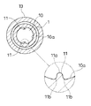
なお、ここで図1〜図3はこの発明を適用して構成されたスクリュグロメットの一例をそれぞれ示しており、図4はかかるスクリュグロメットを留め付け対象物Pに仮止めさせた様子を、図5は図4の状態からスクリュグロメットにタッピングねじNをねじ込んでスクリュグロメットを留め付け対象物Pに本止めした様子を、図6は図5におけるねじ込み穴10内の状態を拡大して、それぞれ示している。また、図7および図8はねじ込み穴10の内面10aに形成される突出部11の形成の仕方を図1〜図6に示される例と異ならせた変更例の要部をそれぞれ示している。
1 to 3 each show an example of a screw grommet configured by applying the present invention, and FIG. 4 is a diagram showing a state in which the screw grommet is temporarily fastened to the object P to be fastened. 5 shows a state in which the tapping screw N is screwed into the screw grommet from the state of FIG. 4 and the screw grommet is fastened to the object P, and FIG. 6 is an enlarged view of the state in the
この実施の形態にかかるスクリュグロメットは、留め付け対象物Pに設けられた取り付け穴Paに脚部2を入れ込ませた状態から、タッピングねじNをねじ込ませることで、この脚部2を拡開させ又は撓み込まないようにして、この脚部2と頭部1との間で留め付け対象物Pを挟みつけてこれに留め付くタイプのものである。
The screw grommet according to this embodiment expands the
かかるスクリュグロメットは、頭部1と、脚部2とを備えている。かかるスクリュグロメットは前記タッピングねじNのねじ込みによって前記脚部2の拡開を生じさせるように、また、タッピングねじNのかかるねじ込みに先立って前記取り付け穴Paに脚部2を弾性変形させながらはめ込むことができるように、プラスチック材料によって構成される。
The screw grommet includes a
頭部1は、パネルなどの留め付け対象物Pの取り付け穴Paに入り込まない大きさを持つように構成される。脚部2は、頭部1と一体をなし、かかる取り付け穴Paに入れ込み可能な太さを持つように構成される。
The
頭部1に貫通状態にタッピングねじNのねじ込み穴10が形成される。このねじ込み穴10の穴径は、ねじ込まれるタッピングねじNの外径より小さくて谷径よりも大きくなるように構成される。例えば、ねじ込まれるタッピングねじNを、JIS規格で定められる呼び径6の4種タッピンねじとする場合、その外径は略φ5.9(5.85~6.0)mmであり、その谷径は略φ4.4mm〜4.6mmであることから、ねじ込み穴10の穴径は例えばφ5.5mm前後に設定される。
A
脚部2は、頭部1と連接される基部2a側から先端2b側に亘って、かかる頭部1に形成されたねじ込み穴10に連通される脚内側空間2cを持つように構成される。典型的には、かかる脚部2は、前記ねじ込み穴10に筒一端を連通させるようにして、頭部1の一面側にこの筒一端を一体に連接させるように形成された筒状体を、その筒他端から筒一端側に向けて続く割溝2dによって、二以上の部分に分割させるようにして構成される。図示の例では、かかる脚部2は、前記タッピングねじNの脚内側空間2c内への入り込み寸法が大きくなるに従って、二以上の脚部2を次第に外側に撓み出させて拡開させるように構成されている。
The
この実施の形態にあっては、前記ねじ込み穴10の内面10aには、ねじ込まれるタッピングねじNのねじ溝Naを埋める突出部11が形成してある。具体的には、この実施の形態にあっては、ねじ込まれるタッピングねじNの外径と谷径との中間の穴径を持つねじ込み穴10の内面10aから、このタッピングねじNのねじ込みに支障を生じさせず、かつ、突出部11の形成位置においてタッピングねじNのねじ溝Naを水密に埋める突きだし寸法を持つように、突出部11が形成されている。
In this embodiment, the
かかるスクリュグロメットは、その頭部1は通さないが脚部2は通す大きさの取り付け穴Paの開設された留め付け対象物P、典型的には、二枚以上のかかる取り付け穴Paを備えたパネルPをそれぞれの取り付け穴Paを連通させるように重ね合わせた状態から、その取り付け穴Paに脚部2を通し、(図4)次いで、頭部1のねじ込み穴10からタッピングねじNをねじ込むことで、かかる頭部1と拡開された脚部2との間で留め付け対象物Pを挟みつけるようにしてこれに留め付けられる。(図5)ねじ込み穴10はタッピングねじNの外径と谷径との中間の穴径であることから、かかるねじ込みに過大な力を必要としないようにすることができる。このようにねじ込まれたタッピングねじNとねじ込み穴10との間に水などの液体が入り込む状況では、かかるタッピングねじNのねじ溝Naがかかる液体の流路となり得るが、前記突出部11の形成位置においてこの突出部11がねじ溝Naを水密に埋めることから、この形成位置から先への液体の進入を阻止することができる。すなわち、かかるスクリュグロメットによれば、そのねじ込み穴10とタッピングねじNとの間に別途の止水手段、典型的には、タッピングねじNの軸を通してこのタッピングねじNの頭の座となるように機能するリング状のシール部材などを用いなくても、タッピングねじNとねじ込み穴10との間を液密にシールさせることができる。
Such a screw grommet is provided with a fastening object P having a mounting hole Pa that is large enough to pass the
図示の例では、頭部1は、ねじ込み穴10を中心にしたフランジ状部分12を有している。かかるフランジ状部分12は、円盤状をなすように構成されている。フランジ状部分12の一面12a側には、内側をねじ込み穴10とした短寸筒状部13がその筒一端をこのフランジ状部分12の一面12aに一体に連接させるようにして突きだし状に備えられている。この短寸筒状部13の筒他端では、ねじ込み穴10は拡径となっており、この拡径部10bにおけるねじ込み穴10の穴軸方向にある面は短寸筒状部13の筒一端側に向かうに連れて次第にこの拡径部10bの径を狭める向きに傾斜したタッピングねじNの導入案内面10cとなっている。
In the illustrated example, the
また、図示の例では、脚部2は、筒一端をフランジ状部分12の他面12bに一体に連接させて筒内空間をねじ込み穴10に連通させると共に、筒他端を開放させた外側の形状を角筒様とするように構成されている。かかる脚部2の外郭形状は、留め付け対象物Pの取り付け穴Paの穴形状に倣わされており、タッピングねじNのねじ込み時にスクリュグロメット側が連れ回りしないようになっている。脚部2の内側は、円形のねじ込み穴10の内面10aに連続した弧状の内面2eがその基部2aから先端2b側に亘って形成されており、かかる脚部2の内面2eは概ね脚部2の突きだし方向に直交する向きの断面において仮想の円の円弧上に位置されるようになっている。脚部2の内面2eのなす内径は脚部2の基部2a側から先端2b側に向かうに連れて次第に小さくなっている。
Further, in the example shown in the figure, the
図示の例では、かかる脚部2は、その先端2bから基部2aに亘る割溝2dによって二分されている。具体的には、外側を角筒様とする脚部2の背中合わせの向きにある両側面の略中央がそれぞれ、前記割溝2dによって二分されており、二箇所のかかる割溝2dによって脚部2は二分割されている。また、かかる脚部2は、その基部2aから筒軸方向略中程の位置2fに向けて次第にその外側を太め、この中程の位置2fからその先端2bに向けて次第にその外側を細めるように構成されていると共に、この中程の位置2fの太さを前記取り付け穴Paの穴幅よりもやや大きくさせている。これにより、図示の例では、留め付け対象物Pの取り付け穴Paに脚部2を入れ込むことで、脚部2を内向きに一旦弾性変形させた後に、前記中程の位置2fが取り付け穴Paの入れ込み先側の穴縁から抜け出した位置でこれを弾性復帰させて取り付け穴Paに仮止めできるようになっている。(図4)
In the illustrated example, the
また、図示の例では、前記突出部11は、ねじ込み穴10の直径方向両側にそれぞれ形成されている。それぞれの突出部11はねじ込み穴10の穴軸に沿って続くリブ状をなすように構成されており、頭部1の短寸筒状部13の拡径部10bの内端から始まり脚部2の先端2b側まで続いている。脚部2の内側は前記のようにその先端2bに向かうに連れて次第に狭くなるように構成されていることから、かかる突出部11は脚部2の先端2b側に向かうに連れて相対的に次第に低まり、脚部2の先端2b側では脚部2の内面2eに連続するに至る。これによって、頭部1内においてねじ込まれるタッピングねじNのねじ溝Naをその螺旋のいずれかの位置で確実に前記突出部11によって埋めることができるようになっている。図示の例では、かかる構造により、かかる突出部11の少なくとも一部が前記フランジ状部分12におけるねじ込み穴10の内面10aに形成されていると共に、このフランジ状部分12が、ねじ込まれるタッピングねじNの1ピッチ分の寸法以上の厚さを備えるようにしてある。フランジ状部分12は剛性が高くなることから、このようにすることで、このフランジ状部分12の内側においてねじ込まれるタッピングねじNのねじ溝Naにこのねじ込みによって前記突出部11をしっかりと確実に埋め込ませることができる。
In the illustrated example, the
かかる突出部11は、図7および図8に示されるように、ねじ込み穴10内において、その周方向に続くように形成させておいても良い。このようにした場合にも、頭部1内においてねじ込まれるタッピングねじNのねじ溝Naをその螺旋のいずれかの位置で確実にかかる突出部11によって埋めることができる。この場合には、突出部11はねじ込み穴10の全周に亘って形成させずに、このねじ込み穴10の周方向において、隣り合う突出部11との間に隙間14を形成させて二以上に分割させて形成させる。タッピングねじNのねじ込み時にかかる隙間14を肉逃しとして機能させることができ、タッピングねじNのねじ込みに必要な力を軽減させることができる。
As shown in FIGS. 7 and 8, the
また、図示の例では、ねじ込み穴10の穴軸に直交する向きの断面において、突出部11の頂部11aと裾部11bとが共にアール状をなすように形成されている。(図3)具体的には、突出部11は前記断面形状において頂部11aをドーム状にし、また、両裾部11b、11bはねじ込み穴10の内方を湾曲内側とするように湾曲されている。このようにすると、タッピングねじNのねじ込み時に突出部11はねじ山により傷つけられるがこのときに破断してねじ込み穴10の内面10aから掻き取られないようにすることができ、また、タッピングねじNのねじ込みに支障を与えない態様で突出部11の肉量を増加させることができる。
Further, in the illustrated example, both the
突出部11を、ねじ込まれるタッピングねじNの谷底に接する仮想的な円筒の周面よりも、言い換えれば、タッピングねじNの谷径を直径とする仮想的な円の円弧よりも、0.1mm〜0.2mmの範囲内でこの円内に入り込むように、ねじ込み穴10の内面10aから突き出させ、ねじ込み穴10の穴径をφ5.5mmにして、JIS規格で定められる呼び径6のタッピンねじをねじ込ませたところ、このねじ込みはスムースになせた一方、このタッピンねじとねじ込み穴10との間は確実に止水できた。
The protruding
なお、図示の例では、脚部2の通し穴3aを備えたゴム又はゴム状弾性を備えたプラスチックよりなる板状シール材3のこの通し穴3aに脚部2を通した状態で、留め付け対象物Pの取り付け穴Paにこの脚部2を入れ込み、タッピングねじNのねじ込みをなすようにしてあり、フランジ状部分12の他面12bと留め付け対象物Pとの間の止水はこの板状シール材3によってなすようになっている。
In the illustrated example, the
1 頭部
10 ねじ込み穴
10a 内面
11 突出部
2 脚部
N タッピングねじ
Na ねじ溝
DESCRIPTION OF
Claims (7)
ねじ込み穴の穴径は、前記タッピングねじの外径より小さくて谷径よりも大きくなっていると共に、
ねじ込み穴の内面に、ねじ込まれるタッピングねじのねじ溝を埋める突出部が形成してあることを特徴とするスクリュグロメット。 A plastic screw grommet having a head with a tapping screw screw hole and a leg portion that is widened or prevented from bending by tapping screw screwing,
The hole diameter of the screw hole is smaller than the outer diameter of the tapping screw and larger than the valley diameter,
A screw grommet characterized in that a protrusion for filling a screw groove of a tapping screw to be screwed is formed on the inner surface of the screw hole.
Priority Applications (7)
| Application Number | Priority Date | Filing Date | Title |
|---|---|---|---|
| JP2008075268A JP5054587B2 (en) | 2008-03-24 | 2008-03-24 | Screw grommet |
| PCT/JP2009/055446 WO2009119446A1 (en) | 2008-03-24 | 2009-03-19 | Screw grommet |
| KR1020107019921A KR20100109570A (en) | 2008-03-24 | 2009-03-19 | Screw grommet |
| ES09723665.7T ES2493019T3 (en) | 2008-03-24 | 2009-03-19 | Screw washer |
| US12/736,219 US8931988B2 (en) | 2008-03-24 | 2009-03-19 | Screw grommet |
| EP09723665.7A EP2275691B1 (en) | 2008-03-24 | 2009-03-19 | Screw grommet |
| CN200980110172.1A CN101978177B (en) | 2008-03-24 | 2009-03-19 | Screw grommet |
Applications Claiming Priority (1)
| Application Number | Priority Date | Filing Date | Title |
|---|---|---|---|
| JP2008075268A JP5054587B2 (en) | 2008-03-24 | 2008-03-24 | Screw grommet |
Publications (2)
| Publication Number | Publication Date |
|---|---|
| JP2009228802A true JP2009228802A (en) | 2009-10-08 |
| JP5054587B2 JP5054587B2 (en) | 2012-10-24 |
Family
ID=41113641
Family Applications (1)
| Application Number | Title | Priority Date | Filing Date |
|---|---|---|---|
| JP2008075268A Active JP5054587B2 (en) | 2008-03-24 | 2008-03-24 | Screw grommet |
Country Status (7)
| Country | Link |
|---|---|
| US (1) | US8931988B2 (en) |
| EP (1) | EP2275691B1 (en) |
| JP (1) | JP5054587B2 (en) |
| KR (1) | KR20100109570A (en) |
| CN (1) | CN101978177B (en) |
| ES (1) | ES2493019T3 (en) |
| WO (1) | WO2009119446A1 (en) |
Cited By (1)
| Publication number | Priority date | Publication date | Assignee | Title |
|---|---|---|---|---|
| JP2013023893A (en) * | 2011-07-20 | 2013-02-04 | Kaneka Corp | Fastener, fixing method of solar cell module fixing device, and roof structure |
Families Citing this family (20)
| Publication number | Priority date | Publication date | Assignee | Title |
|---|---|---|---|---|
| US8661614B2 (en) | 2011-08-17 | 2014-03-04 | Symmetry Medical Manufacturing, Inc. | Grommet device with flexible bowed members and methods of using thereof |
| US8701246B2 (en) * | 2011-09-14 | 2014-04-22 | Symmetry Medical Manufacturing, Inc. | Removable grommet device and method of using thereof |
| US8739363B2 (en) | 2011-09-14 | 2014-06-03 | Symmetry Medical Manufacturing, Inc. | Removable grommet device with enlargeable slit and method thereof |
| US9277967B2 (en) | 2011-09-14 | 2016-03-08 | Symmetry Medical Manufacturing, Inc. | Universally-sized grommet device and method thereof |
| US9915282B2 (en) * | 2012-06-06 | 2018-03-13 | Pneutools, Incorporated | Stacked caps with connecting stems |
| US9599140B2 (en) | 2014-08-28 | 2017-03-21 | Newfrey Llc | Plastic serviceable screw grommet and related methods |
| CN105716321B (en) * | 2014-12-01 | 2019-03-05 | 青岛海尔特种电冰柜有限公司 | Semiconductor refrigeration equipment |
| WO2017011884A1 (en) * | 2015-07-23 | 2017-01-26 | Cermag Comercial Importadora E Exportadora Ltda. | Structural arrangement in component for mounting and fastening a profile pull handle |
| JP6395321B2 (en) * | 2015-10-26 | 2018-09-26 | 株式会社ニフコ | Grommet |
| CN105402232A (en) * | 2016-01-11 | 2016-03-16 | 太仓市德浩紧固件有限公司 | Self-tapping screw |
| US20170284567A1 (en) * | 2016-03-30 | 2017-10-05 | The Boeing Company | Grommet, conduit support assembly, and method of supporting a conduit |
| CN107269168A (en) * | 2017-08-21 | 2017-10-20 | 贵州协成装饰工程有限公司 | A kind of outer casement window of combined type |
| CN107313689A (en) * | 2017-08-21 | 2017-11-03 | 贵州协成装饰工程有限公司 | A kind of window frame reversion section bar and window frame attachment structure |
| ES2708863B2 (en) * | 2017-10-10 | 2020-03-25 | Itw Espana Sa | Parts fixing device |
| US10941801B2 (en) * | 2017-12-20 | 2021-03-09 | Bombardier Recreational Products Inc. | Anchor assembly |
| DE102019101078A1 (en) | 2018-01-16 | 2019-07-18 | Illinois Tool Works Inc. | NIET FASTENER ELEMENT DESIGN AND METHOD OF USE THEREOF |
| US11268557B2 (en) * | 2018-10-10 | 2022-03-08 | Illinois Tool Works Inc. | Rivet fastener assembly and method of use thereof |
| ES3031657T3 (en) * | 2019-10-09 | 2025-07-10 | Doka Gmbh | Anchor |
| DE202022000594U1 (en) | 2022-03-09 | 2022-03-17 | Wenko-Wenselaar GmbH & Co. Kommanditgesellschaft | Device for attaching an object to packaging |
| CN114838047B (en) * | 2022-05-19 | 2024-02-06 | 浙江洪扬汽车零部件有限公司 | Lock screw for mechanical equipment |
Citations (3)
| Publication number | Priority date | Publication date | Assignee | Title |
|---|---|---|---|---|
| JPH0539808A (en) * | 1991-05-30 | 1993-02-19 | Mitsubishi Cable Ind Ltd | Seal washer |
| JPH07259824A (en) * | 1994-02-15 | 1995-10-09 | Itw Ateco Gmbh | Rivet made of plastic fixing tabular work onto supporter with flat surface |
| JP2002213417A (en) * | 2001-01-15 | 2002-07-31 | Nifco Inc | Fastener |
Family Cites Families (30)
| Publication number | Priority date | Publication date | Assignee | Title |
|---|---|---|---|---|
| US1051444A (en) * | 1911-07-18 | 1913-01-28 | Henry B Newhall | Bolt-anchor. |
| US1248009A (en) * | 1917-01-20 | 1917-11-27 | Henry B Newhall | Bolt-anchor. |
| US1248004A (en) * | 1917-01-20 | 1917-11-27 | Henry B Newhall | Bolt-anchor. |
| US1248008A (en) * | 1917-01-20 | 1917-11-27 | Henry B Newhall | Bolt-anchor. |
| US1751818A (en) * | 1928-09-28 | 1930-03-25 | Newhall Henry B Corp | Bolt anchor |
| US1754333A (en) * | 1929-02-15 | 1930-04-15 | Newhall Henry B Corp | Bolt anchor |
| DE1207065B (en) * | 1960-05-14 | 1965-12-16 | Artur Fischer | Expanding dowel |
| JPS5338053Y2 (en) * | 1974-04-18 | 1978-09-14 | ||
| US4082030A (en) * | 1977-03-25 | 1978-04-04 | Illinois Tool Works, Inc. | Plastic screw grommet |
| JPS5653124Y2 (en) * | 1977-10-08 | 1981-12-11 | ||
| US4233881A (en) * | 1978-05-05 | 1980-11-18 | Carrier Vernon J | Wall fastener structure |
| JPS5572903A (en) * | 1978-11-21 | 1980-06-02 | Nifco Inc | Screw grommet |
| JPS5824646A (en) | 1981-08-06 | 1983-02-14 | Kazuichi Ito | Rocking type fluid-tight drive unit |
| JPS5958206U (en) | 1982-10-12 | 1984-04-16 | 株式会社青山製作所 | Synthetic resin grommet |
| US4601625A (en) * | 1984-05-11 | 1986-07-22 | Illinois Tool Works Inc. | Self drilling threaded insert for drywall |
| JPH045766Y2 (en) * | 1984-09-07 | 1992-02-18 | ||
| JPH0435612Y2 (en) * | 1988-07-08 | 1992-08-24 | ||
| JPH0343107U (en) * | 1989-09-04 | 1991-04-23 | ||
| IT224172Z2 (en) * | 1991-01-18 | 1996-02-09 | Fischer Italia Di Paolo Morasu | GASKET ELEMENT AND SPACING FOR SHEET ANCHORING DEVICES FOR WALL COVERING |
| US5294225A (en) * | 1991-11-21 | 1994-03-15 | K.K. Aoyama Seisakusho | Synthetic resin grommet |
| JP2605155Y2 (en) | 1992-08-31 | 2000-06-26 | 株式会社パイオラックス | Screw grommet |
| JP2604678Y2 (en) | 1992-09-18 | 2000-05-22 | 株式会社東郷製作所 | Grommet |
| DE9413434U1 (en) * | 1994-08-19 | 1995-12-21 | Fischerwerke Artur Fischer Gmbh & Co Kg, 72178 Waldachtal | Plastic expansion anchors |
| ES2143669T3 (en) * | 1994-11-23 | 2000-05-16 | Cobra Anchors Co Ltd | IMPROVEMENT IN AN ANCHOR INSERT. |
| DE19607446A1 (en) * | 1996-02-28 | 1997-09-04 | Adolf Wuerth Gmbh & Co Kg | Knock-in dowels |
| DE19930728B4 (en) * | 1999-07-05 | 2005-12-01 | Itw-Ateco Gmbh | Anchor for fixing an object to a carrier made of flat material |
| JP2004044644A (en) * | 2002-07-10 | 2004-02-12 | Nippon Pop Rivets & Fasteners Ltd | Screw grommet |
| ITTO20030279A1 (en) * | 2003-04-11 | 2004-10-12 | Itw Construction Products Italy Srl | EXPANSION DOWEL. |
| US7001124B2 (en) * | 2004-02-05 | 2006-02-21 | Illinois Tool Works Inc. | Anchor |
| CN201100290Y (en) * | 2007-11-13 | 2008-08-13 | 邹海微 | Expansion pipe |
-
2008
- 2008-03-24 JP JP2008075268A patent/JP5054587B2/en active Active
-
2009
- 2009-03-19 KR KR1020107019921A patent/KR20100109570A/en not_active Ceased
- 2009-03-19 CN CN200980110172.1A patent/CN101978177B/en active Active
- 2009-03-19 EP EP09723665.7A patent/EP2275691B1/en active Active
- 2009-03-19 ES ES09723665.7T patent/ES2493019T3/en active Active
- 2009-03-19 US US12/736,219 patent/US8931988B2/en active Active
- 2009-03-19 WO PCT/JP2009/055446 patent/WO2009119446A1/en not_active Ceased
Patent Citations (3)
| Publication number | Priority date | Publication date | Assignee | Title |
|---|---|---|---|---|
| JPH0539808A (en) * | 1991-05-30 | 1993-02-19 | Mitsubishi Cable Ind Ltd | Seal washer |
| JPH07259824A (en) * | 1994-02-15 | 1995-10-09 | Itw Ateco Gmbh | Rivet made of plastic fixing tabular work onto supporter with flat surface |
| JP2002213417A (en) * | 2001-01-15 | 2002-07-31 | Nifco Inc | Fastener |
Cited By (1)
| Publication number | Priority date | Publication date | Assignee | Title |
|---|---|---|---|---|
| JP2013023893A (en) * | 2011-07-20 | 2013-02-04 | Kaneka Corp | Fastener, fixing method of solar cell module fixing device, and roof structure |
Also Published As
| Publication number | Publication date |
|---|---|
| EP2275691B1 (en) | 2014-06-11 |
| CN101978177A (en) | 2011-02-16 |
| ES2493019T3 (en) | 2014-09-11 |
| KR20100109570A (en) | 2010-10-08 |
| CN101978177B (en) | 2012-08-29 |
| US8931988B2 (en) | 2015-01-13 |
| US20110091301A1 (en) | 2011-04-21 |
| EP2275691A1 (en) | 2011-01-19 |
| EP2275691A4 (en) | 2013-01-02 |
| WO2009119446A1 (en) | 2009-10-01 |
| JP5054587B2 (en) | 2012-10-24 |
Similar Documents
| Publication | Publication Date | Title |
|---|---|---|
| JP5054587B2 (en) | Screw grommet | |
| US8656553B2 (en) | Grommet for wire harness | |
| US8704098B2 (en) | Grommet | |
| JP3825278B2 (en) | Grommet | |
| US20130008693A1 (en) | Grommet for wire harness | |
| JP2014033564A (en) | Grommet | |
| JP2018046704A (en) | Grommet mounting structure | |
| US8545155B2 (en) | Attachment fastener with a sealing washer | |
| KR20180112849A (en) | Gromit | |
| CN108352692B (en) | Wire sheath and wire harness | |
| JP2016005405A (en) | Assembling structure of grommet | |
| JP4482327B2 (en) | Grommet | |
| JP2008507245A (en) | Connecting member for corrugated tubes | |
| KR20100008363U (en) | Adhesive Anchors | |
| JP6256254B2 (en) | Grommet | |
| JP4205607B2 (en) | Grommet | |
| JP5724740B2 (en) | Grommet | |
| JP5147477B2 (en) | Grommet for back door | |
| JP6146267B2 (en) | Grommet | |
| JP2012235640A (en) | Grommet | |
| JP2007227026A (en) | Grommet | |
| JP5760659B2 (en) | Grommet | |
| JP5270117B2 (en) | Grommet | |
| JP2017175742A (en) | Grommet | |
| JPH10247431A (en) | Grommet |
Legal Events
| Date | Code | Title | Description |
|---|---|---|---|
| A621 | Written request for application examination |
Free format text: JAPANESE INTERMEDIATE CODE: A621 Effective date: 20100723 |
|
| A131 | Notification of reasons for refusal |
Free format text: JAPANESE INTERMEDIATE CODE: A131 Effective date: 20120515 |
|
| A521 | Request for written amendment filed |
Free format text: JAPANESE INTERMEDIATE CODE: A523 Effective date: 20120625 |
|
| TRDD | Decision of grant or rejection written | ||
| A01 | Written decision to grant a patent or to grant a registration (utility model) |
Free format text: JAPANESE INTERMEDIATE CODE: A01 Effective date: 20120724 |
|
| A01 | Written decision to grant a patent or to grant a registration (utility model) |
Free format text: JAPANESE INTERMEDIATE CODE: A01 |
|
| A61 | First payment of annual fees (during grant procedure) |
Free format text: JAPANESE INTERMEDIATE CODE: A61 Effective date: 20120727 |
|
| R150 | Certificate of patent or registration of utility model |
Ref document number: 5054587 Country of ref document: JP Free format text: JAPANESE INTERMEDIATE CODE: R150 Free format text: JAPANESE INTERMEDIATE CODE: R150 |
|
| FPAY | Renewal fee payment (event date is renewal date of database) |
Free format text: PAYMENT UNTIL: 20150803 Year of fee payment: 3 |
|
| R250 | Receipt of annual fees |
Free format text: JAPANESE INTERMEDIATE CODE: R250 |
|
| R250 | Receipt of annual fees |
Free format text: JAPANESE INTERMEDIATE CODE: R250 |
|
| R250 | Receipt of annual fees |
Free format text: JAPANESE INTERMEDIATE CODE: R250 |
|
| R250 | Receipt of annual fees |
Free format text: JAPANESE INTERMEDIATE CODE: R250 |
|
| R250 | Receipt of annual fees |
Free format text: JAPANESE INTERMEDIATE CODE: R250 |
|
| R250 | Receipt of annual fees |
Free format text: JAPANESE INTERMEDIATE CODE: R250 |
|
| R250 | Receipt of annual fees |
Free format text: JAPANESE INTERMEDIATE CODE: R250 |
|
| R250 | Receipt of annual fees |
Free format text: JAPANESE INTERMEDIATE CODE: R250 |
|
| R250 | Receipt of annual fees |
Free format text: JAPANESE INTERMEDIATE CODE: R250 |
|
| R250 | Receipt of annual fees |
Free format text: JAPANESE INTERMEDIATE CODE: R250 |