JP2009240102A - Electronic equipment - Google Patents
Electronic equipment Download PDFInfo
- Publication number
- JP2009240102A JP2009240102A JP2008085125A JP2008085125A JP2009240102A JP 2009240102 A JP2009240102 A JP 2009240102A JP 2008085125 A JP2008085125 A JP 2008085125A JP 2008085125 A JP2008085125 A JP 2008085125A JP 2009240102 A JP2009240102 A JP 2009240102A
- Authority
- JP
- Japan
- Prior art keywords
- battery
- charging
- internal power
- batteries
- secondary battery
- Prior art date
- Legal status (The legal status is an assumption and is not a legal conclusion. Google has not performed a legal analysis and makes no representation as to the accuracy of the status listed.)
- Pending
Links
- 238000013500 data storage Methods 0.000 claims description 7
- 238000000034 method Methods 0.000 description 15
- 230000005856 abnormality Effects 0.000 description 2
- 230000007423 decrease Effects 0.000 description 2
- 230000002159 abnormal effect Effects 0.000 description 1
- 238000010586 diagram Methods 0.000 description 1
- 230000006870 function Effects 0.000 description 1
- 230000002093 peripheral effect Effects 0.000 description 1
- 230000004044 response Effects 0.000 description 1
- 230000000630 rising effect Effects 0.000 description 1
- 230000009466 transformation Effects 0.000 description 1
Images

Classifications
-
- Y—GENERAL TAGGING OF NEW TECHNOLOGICAL DEVELOPMENTS; GENERAL TAGGING OF CROSS-SECTIONAL TECHNOLOGIES SPANNING OVER SEVERAL SECTIONS OF THE IPC; TECHNICAL SUBJECTS COVERED BY FORMER USPC CROSS-REFERENCE ART COLLECTIONS [XRACs] AND DIGESTS
- Y02—TECHNOLOGIES OR APPLICATIONS FOR MITIGATION OR ADAPTATION AGAINST CLIMATE CHANGE
- Y02E—REDUCTION OF GREENHOUSE GAS [GHG] EMISSIONS, RELATED TO ENERGY GENERATION, TRANSMISSION OR DISTRIBUTION
- Y02E60/00—Enabling technologies; Technologies with a potential or indirect contribution to GHG emissions mitigation
- Y02E60/10—Energy storage using batteries
Landscapes
- Charge And Discharge Circuits For Batteries Or The Like (AREA)
- Secondary Cells (AREA)
Abstract
Description
本発明は、複数本の電池からなる内部電源によって動作する電子機器に関するものである。 The present invention relates to an electronic device that is operated by an internal power source including a plurality of batteries.
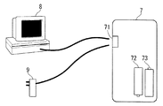
図5に示す如くICレコーダ等の電子機器(7)は、複数本の電池(72)(73)を内蔵し、該電池(72)(73)を電源として動作する。電池(72)(73)としては、一次電池のみならず、充電が可能な二次電池を採用することが可能である。
この種の電子機器(7)においては、電池(72)(73)として二次電池を内蔵した場合、USB端子(71)にACアダプター(9)を接続し、該ACアダプター(9)を商用電源に接続することによって、電池(72)(73)を充電することが可能である。
As shown in FIG. 5, an electronic device (7) such as an IC recorder incorporates a plurality of batteries (72) and (73), and operates using the batteries (72) and (73) as a power source. As the batteries (72) and (73), not only a primary battery but also a rechargeable secondary battery can be adopted.
In this type of electronic device (7), when a secondary battery is incorporated as the battery (72) (73), the AC adapter (9) is connected to the USB terminal (71), and the AC adapter (9) is used for commercial purposes. The battery (72) (73) can be charged by connecting to a power source.
又、USB端子(71)にパーソナルコンピュータ(8)を接続することによって、パーソナルコンピュータ(8)から電子機器(7)に電力を供給して、電池(72)(73)を充電することも可能である。
ここで、ICレコーダ等の電子機器(7)は、USB規格のマスストレージモードのデバイスとなり、パーソナルコンピュータ(8)はホスト側となる。この様な接続状態は規格に基づいているため、電子機器(7)はどの様なパーソナルコンピュータ(8)とも接続が可能であり、特別なドライバーソフトウエアは不要である。
In addition, by connecting a personal computer (8) to the USB terminal (71), it is possible to charge the batteries (72) and (73) by supplying power from the personal computer (8) to the electronic device (7). It is.
Here, the electronic device (7) such as the IC recorder is a USB mass storage mode device, and the personal computer (8) is the host side. Since such a connection state is based on the standard, the electronic device (7) can be connected to any personal computer (8), and no special driver software is required.
従来、複数本の二次電池を電源とする電子機器において、これらの二次電池を良好に充電するための充電装置が提案されている(特許文献1、2、3)。
又、電子機器に内蔵されている複数本の電池の内、少なくとも1本が一次電池であった場合に、その充電を防止する充電装置が提案されている(特許文献4)。
In addition, there has been proposed a charging device that prevents charging when at least one of a plurality of batteries built in an electronic device is a primary battery (Patent Document 4).
しかしながら、電子機器に内蔵されている複数本の電池に一次電池が含まれている場合、従来の電子機器においては、全ての電池に対する充電が停止されてしまい、二次電池だけを選択的に充電することは出来ない。
従って、電子機器に内蔵されている複数本の電池に一次電池と二次電池が混在している場合、電力消費によって先ず二次電池の電圧が低下すると、一次電池に電力が残っていたとしても、二次電池だけを選択的に充電しつつ、一次電池の残容量を完全に消費することが出来ない問題があった。
However, when the primary battery is included in the multiple batteries built into the electronic device, the charging for all the batteries is stopped in the conventional electronic device, and only the secondary battery is selectively charged. I can't do it.
Therefore, when the primary battery and the secondary battery are mixed in a plurality of batteries built in the electronic device, if the voltage of the secondary battery first decreases due to power consumption, even if the power remains in the primary battery. There is a problem that the remaining capacity of the primary battery cannot be completely consumed while selectively charging only the secondary battery.
そこで本発明の目的は、複数本の電池に一次電池と二次電池が混在している場合に、二次電池だけを選択的に充電しつつ、一次電池の残容量を最後まで消費することが出来る電子機器を提供することである。 Therefore, an object of the present invention is to consume the remaining capacity of the primary battery to the end while selectively charging only the secondary battery when the primary battery and the secondary battery are mixed in a plurality of batteries. It is to provide electronic devices that can be used.
本発明に係る電子機器は、複数本の電池からなる内部電源と、該内部電源から電力の供給を受けて動作する動作部とを具え、前記内部電源の充電が可能である。
該電子機器は更に、
内部電源として装着された各電池に対して個別に接続することが可能な充電手段と、
前記充電手段による充電時に、内部電源として装着された複数本の電池について、各電池が一次電池であるか二次電池であるかを判定する判定手段と、
前記判定手段によって二次電池であると判定された電池を前記充電手段によって充電する充電制御手段と、
機器動作中に、内部電源として装着された複数本の電池の残容量が所定の閾値を下回った否かを判断する判断手段と、
前記判断手段によって前記残容量が前記閾値を下回ったと判断されたとき、機器動作を停止させる動作停止手段
とを具えている。
An electronic apparatus according to the present invention includes an internal power supply including a plurality of batteries and an operation unit that operates by receiving power supply from the internal power supply, and the internal power supply can be charged.
The electronic device further includes
Charging means that can be individually connected to each battery mounted as an internal power source;
Determination means for determining whether each battery is a primary battery or a secondary battery for a plurality of batteries mounted as an internal power source during charging by the charging means;
Charging control means for charging the battery determined to be a secondary battery by the determining means by the charging means;
A determination means for determining whether or not the remaining capacity of a plurality of batteries mounted as an internal power source has fallen below a predetermined threshold during the operation of the device;
And an operation stop means for stopping the operation of the device when the determination means determines that the remaining capacity is below the threshold value.
具体的には、前記充電制御手段は、内部電源として装着された各電池に前記充電手段を順次接続し、1つの電池に前記充電手段が接続された状態で、前記判定手段は、該1つの電池が一次電池であるか二次電池であるかを判定し、該1つの電池が二次電池の場合に限り、前記充電制御手段は該1つの電池を充電する。 Specifically, the charging control unit sequentially connects the charging unit to each battery mounted as an internal power source, and the determination unit includes the one charging unit in a state where the charging unit is connected to one battery. Whether the battery is a primary battery or a secondary battery is determined, and only when the one battery is a secondary battery, the charge control means charges the one battery.
上記本発明の電子機器においては、一次電池と二次電池が混在した内部電源からの電力供給によって機器が動作している過程で、先ず二次電池の残容量が所定の閾値を下回ったとき、機器動作は停止する。
そこで、外部電源から電力を供給して内部電源を充電する。この際、内部電源を構成する複数本の電池について、各電池が一次電池であるか二次電池であるかが判定され、二次電池と判定された電池のみが選択的に充電される。これによって、一次電池と二次電池からなる内部電源の電圧が回復し、機器動作が可能となる。
従って、上記の機器動作と充電を繰り返すことにより、一次電池の残容量が最後まで消費されることになる。
In the electronic device of the present invention, when the device is operating by the power supply from the internal power supply mixed with the primary battery and the secondary battery, when the remaining capacity of the secondary battery first falls below a predetermined threshold, Device operation stops.
Therefore, power is supplied from the external power source to charge the internal power source. At this time, it is determined whether each battery is a primary battery or a secondary battery for a plurality of batteries constituting the internal power supply, and only the batteries determined to be secondary batteries are selectively charged. As a result, the voltage of the internal power source composed of the primary battery and the secondary battery is recovered, and the device can be operated.
Therefore, the remaining capacity of the primary battery is consumed to the end by repeating the above-described device operation and charging.
更に具体的な構成において、前記判断手段によって前記残容量が前記閾値を下回ったと判断されたとき、前記動作停止手段によって機器動作を停止させる前に、データ保存を含む必要な処理を実行する処理手段を更に具えている。
該具体的構成によれば、機器の動作中に内部電源の電力消費によって残容量が閾値を下回ったとき、先ずデータ保存を含む必要な処理が実行された後、機器動作が停止する。従って、内部電源に確保されている必要最小限の電力によって、データ保存を含む必要な処理が確実に実行され、データが消失することはない。
In a more specific configuration, when the determination unit determines that the remaining capacity is lower than the threshold value, the processing unit executes necessary processing including data storage before stopping the device operation by the operation stop unit. Is further provided.
According to this specific configuration, when the remaining capacity falls below the threshold due to the power consumption of the internal power supply during the operation of the device, the device operation is stopped after the necessary processing including data storage is first executed. Therefore, necessary processing including data storage is reliably executed by the minimum necessary power secured in the internal power source, and data is not lost.
本発明に係る電子機器によれば、複数本の電池に一次電池と二次電池が混在している場合に、二次電池だけを選択的に充電しつつ、一次電池の残容量を最後まで消費することが出来る。 According to the electronic device of the present invention, when the primary battery and the secondary battery are mixed in a plurality of batteries, the remaining capacity of the primary battery is consumed to the end while selectively charging only the secondary battery. I can do it.
以下、本発明をICレコーダに実施した形態につき、図面に沿って具体的に説明する。該ICレコーダは、図5に示す電子機器(7)と同様にUSB端子(71)を具え、例えば該USB端子(71)にUSBケーブルを介してパーソナルコンピュータ(8)を接続することによって、ホスト側から供給される電源(5V/500mA)を利用して内部電源を充電することが出来る。 Hereinafter, embodiments of the present invention implemented in an IC recorder will be specifically described with reference to the drawings. The IC recorder has a USB terminal (71) as in the electronic device (7) shown in FIG. 5. For example, by connecting a personal computer (8) to the USB terminal (71) via a USB cable, The internal power supply can be charged using the power supply (5V / 500mA) supplied from the side.
本発明に係るICレコーダは図1に示す如く、内部電源として、複数本の電池(11)(12)を直列に接続してなる電池群(1)を内蔵しており、該電池群(1)のプラス端子部は、機器駆動電圧源に接続されると共に、マイナス端子部はアースに接続されている。これによって、電池群(1)の電力が機器駆動電圧源へ供給され、機器が動作する。
尚、図示する電池群(1)は2本の電池(11)(12)を直列に接続して構成されているが、2以上の複数本の電池を直列/並列に接続して電池群(1)を構成することも可能である。
As shown in FIG. 1, the IC recorder according to the present invention incorporates a battery group (1) formed by connecting a plurality of batteries (11) and (12) in series as an internal power source. ) Is connected to the device drive voltage source, and the minus terminal is connected to the ground. Thereby, the electric power of the battery group (1) is supplied to the device drive voltage source, and the device operates.
The illustrated battery group (1) is formed by connecting two batteries (11) and (12) in series, but two or more batteries are connected in series / parallel. It is also possible to configure 1).
電池群(1)を構成する2本の電池(11)(12)の間にはオン/オフスイッチ(2)が介在し、該オン/オフスイッチ(2)は、制御回路(5)によってオン/オフ制御されている。
又、電池群(1)を構成する2本の電池(11)(12)には周知の充電回路(6)が接続され、該充電回路(6)は制御回路(5)によって動作が制御されている。これによって、各電池を個別に充電することが可能である。
An on / off switch (2) is interposed between the two batteries (11) and (12) constituting the battery group (1). The on / off switch (2) is turned on by the control circuit (5). / Off controlled.
A well-known charging circuit (6) is connected to the two batteries (11) and (12) constituting the battery group (1), and the operation of the charging circuit (6) is controlled by the control circuit (5). ing. Thereby, it is possible to charge each battery individually.
更に、電池群(1)を構成する2本の電池(11)(12)は、それぞれのプラス端子部が切り換えスイッチ(3)を介して電圧検出器(4)に接続されており、切り換えスイッチ(3)の切り換えによって、各電池の電圧を個別に測定することが可能となっている。
電圧検出器(4)にて検出された各電池の電圧は制御回路(5)へ供給され、これに応じて制御回路(5)は、オン/オフスイッチ(2)、切り換えスイッチ(3)、及び充電回路(6)に対する制御信号を作成する。
Further, the two batteries (11) and (12) constituting the battery group (1) have their positive terminals connected to the voltage detector (4) via the selector switch (3). By switching (3), the voltage of each battery can be measured individually.
The voltage of each battery detected by the voltage detector (4) is supplied to the control circuit (5). In response to this, the control circuit (5) switches the on / off switch (2), the changeover switch (3), And a control signal for the charging circuit (6).
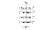
図2は、制御回路(5)の制御によって電池群(1)を充電する手続きを表わしている。充電時には、ICレコーダのUSB端子にパーソナルコンピュータ或いはACアダプターを接続する。 FIG. 2 shows a procedure for charging the battery group (1) under the control of the control circuit (5). When charging, a personal computer or an AC adapter is connected to the USB terminal of the IC recorder.
先ず、ステップS1では、オン/オフスイッチ(2)を開くと共に切り換えスイッチ(3)を切り換えることによって、一方の電池Aのみに電圧検出器(4)と充電回路(6)を接続する。次に、ステップS2では、該電池Aを対象とする一連の充電制御を実行する。
その後、ステップS3では、切り換えスイッチ(3)を切り換えることによって、他方の電池Bのみに電圧検出器(4)と充電回路(6)を接続する。次に、ステップS4では、該電池Bを対象とする一連の充電制御を実行する。
First, in step S1, the voltage detector (4) and the charging circuit (6) are connected to only one battery A by opening the on / off switch (2) and switching the changeover switch (3). Next, in step S2, a series of charge control for the battery A is executed.
Thereafter, in step S3, the voltage detector (4) and the charging circuit (6) are connected to only the other battery B by switching the changeover switch (3). Next, in step S4, a series of charge control for the battery B is executed.
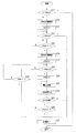
図3は、各電池を対象とする一連の充電制御の具体的処理を表わしている。
先ずステップS11では、対象とする電池の電圧が1.7V以上であるかどうかを判断することによって、異常電圧のチェックを行なう。電池が一次電池であっても二次電池であっても、正常な電池であれば、電圧が1.7Vを越えることはない。
FIG. 3 shows a specific process of a series of charge control for each battery.
First, in step S11, an abnormal voltage is checked by determining whether or not the voltage of the target battery is 1.7V or higher. Regardless of whether the battery is a primary battery or a secondary battery, the voltage will not exceed 1.7V as long as it is a normal battery.
次にステップS12では、100mAの定電流によって充電を開始した後、ステップS13にてタイマをスタートする。そして、ステップS14では、電池の電圧が1.8V以上となったか否かを判断し、ここでノーと判断されたときは、ステップS15にてタイムオーバーとなったか否かを判断し、ノーの場合はステップS14に戻って、電圧の判断を繰り返す。 Next, in step S12, charging is started with a constant current of 100 mA, and then a timer is started in step S13. In step S14, it is determined whether or not the voltage of the battery has become 1.8 V or higher. If it is determined that the battery voltage has been exceeded, it is determined whether or not the time is over in step S15. Returns to step S14 and repeats the determination of the voltage.
もし電池がアルカリ電池等の一次電池であれば、ステップS12での充電によって急速に電圧が上昇することになるので、ステップS15でタイムオーバーとなるまでに、ステップS14でイエスと判断されて、ステップS25に移行し、充電を終了する。
これに対し、電池が二次電池であれば、ステップS12での充電による電圧上昇は緩やかであるので、ステップS14でノーと判断された後、ステップS15でタイムオーバーとなり、ステップS16に移行する。
If the battery is a primary battery such as an alkaline battery, the voltage rapidly rises due to the charging in step S12. Therefore, it is determined as YES in step S14 until the time is over in step S15, and step S25. To finish charging.
On the other hand, if the battery is a secondary battery, the voltage increase due to charging in step S12 is gradual, so that it is determined NO in step S14, the time is over in step S15, and the process proceeds to step S16.
ステップS16では、二次電池を対象とする500mAの電流による高速充電を開始し、ステップS17ではタイマをスタートする。その後、ステップS18では電池電圧が所定の閾値1.15V以上となったか否かを判断する。
ここで、電池の満充電の検出は、電圧が所定の閾値1.15Vに達した後の電圧上昇カーブをチェックすることで行なう。即ち、ステップS18でノーと判断されたときは、ステップS19にてタイムオーバーとなったか否かを判断し、ノーの場合はステップS18に戻って電圧の判断を行なう。ステップS19にてタイムオーバーとなったときは、異常と判断してステップS25にて充電を終了する。
In step S16, fast charging with a current of 500 mA for the secondary battery is started, and in step S17, a timer is started. Thereafter, in step S18, it is determined whether or not the battery voltage is equal to or higher than a predetermined threshold value 1.15V.
Here, the full charge of the battery is detected by checking a voltage increase curve after the voltage reaches a predetermined threshold value of 1.15V. That is, when it is determined NO in step S18, it is determined whether or not the time is over in step S19. If NO, the process returns to step S18 to determine the voltage. If the time is over in step S19, it is determined that there is an abnormality, and charging is terminated in step S25.
電圧の上昇によりステップS18でイエスと判断されたときは、電圧上昇カーブのチェックに移行し、ステップS20ではタイマをスタートし、ステップS21では、その時点の電圧を記憶する。そして、ステップS22では、一定時間のウエイト(待機)を経た後、ステップS23にて、一定時間後の電圧上昇ΔVが所定の定数を越えているか否かを判断する。 When it is determined YES in step S18 due to the voltage rise, the process proceeds to a voltage rise curve check, a timer is started in step S20, and the current voltage is stored in step S21. In step S22, after waiting for a certain time (standby), it is determined in step S23 whether or not the voltage increase ΔV after a certain time exceeds a predetermined constant.
ステップS23にてイエスと判断されたときは、電圧が依然として上昇中であるので、ステップS24でタイムオーバーとなったか否かを判断し、ノーの場合はステップS21に戻って、電圧上昇カーブのチェックを継続する。尚、ステップS24でイエスと判断されたときは、異常の発生と判断して、ステップS25にて充電を終了する。
その後、電圧上昇カーブが飽和域に達すると、ステップS23でノーと判断され、ステップS25に移行して充電を終了する。
If it is determined as YES in step S23, the voltage is still rising, so it is determined whether or not the time is over in step S24. If NO, the process returns to step S21 to check the voltage increase curve. continue. If it is determined as YES in step S24, it is determined that an abnormality has occurred, and charging is terminated in step S25.
Thereafter, when the voltage increase curve reaches the saturation region, it is determined NO in step S23, and the process proceeds to step S25 to end the charging.
上記一連の充電制御を各電池に実行することによって、二次電池のみを対象とする充電が順次実施されることなる。この結果、複数の電池からなる内部電源の電圧が回復する。 By executing the above series of charging control for each battery, charging for only the secondary battery is sequentially performed. As a result, the voltage of the internal power source composed of a plurality of batteries is recovered.
充電終了後は、ICレコーダのUSB端子からパーソナルコンピュータやACアダプターを切り離し、録音や再生などの動作を行なわせる。
この場合、図1に示すオン/オフスイッチ(2)を閉じて2本の電池(11)(12)を直列接続し、電池群(1)の電力を機器駆動電圧源へ供給する。
After charging is completed, the personal computer and AC adapter are disconnected from the USB terminal of the IC recorder, and operations such as recording and playback are performed.
In this case, the on / off switch (2) shown in FIG. 1 is closed, the two batteries (11) and (12) are connected in series, and the power of the battery group (1) is supplied to the device drive voltage source.
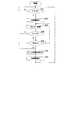
図4は、ICレコーダを動作させるときの制御動作を表わしている。
先ずステップS31では、ユーザによるパワーオンの操作が行なわれたか否かを判断し、ここでイエスと判断されたときは、ステップS32にて、内部電源をオンとし、ステップS33では、録音や再生などのICレコーダ制御を開始する。
FIG. 4 shows a control operation when the IC recorder is operated.
First, in step S31, it is determined whether or not a power-on operation has been performed by the user. If the determination is yes, the internal power supply is turned on in step S32. In step S33, recording or playback is performed. IC recorder control is started.
次に、ステップS34では、ユーザによるパワーオフの操作が行なわれたか否かを判断し、ここでノーと判断されたときは、ステップS35に移行して、内部電源の電圧が機器動作可能な閾値電圧(例えば2V)以上であるか否かを判断する。ここでイエスと判断されたときは、ステップS33に戻って、録音や再生などのICレコーダ制御を継続する。 Next, in step S34, it is determined whether or not a power-off operation has been performed by the user. If NO is determined in this step, the process proceeds to step S35, in which the internal power supply voltage is a threshold at which the device can operate. It is determined whether or not the voltage is greater than or equal to 2V (eg, 2V). If YES is determined here, the process returns to step S33 to continue IC recorder control such as recording and reproduction.
尚、内部電源の電圧が機器動作可能な閾値電圧を上回っているかどうかの判断では、その判断精度を上げるために、負荷状態に応じて閾値電圧を変化させるなどの処理が行なわれる(特許第1050881号参照)。 In determining whether or not the voltage of the internal power supply exceeds the threshold voltage at which the device can operate, processing such as changing the threshold voltage according to the load state is performed in order to increase the determination accuracy (Japanese Patent No. 1050881). Issue).
その後、電力消費によって内部電源の電圧が低下し、ステップS35にてノーと判断されたときは、ステップS36にて、データ保管処理(録音中のデータをフラッシュメモリにセーブする処理)などの必要な処理を実行する。この時点で、内部電源には、データ保管処理などの必要な処理を実行するのに必要な電力は残存している。
必要な処理の終了後、ステップS37にて内部電源をオフとした後、ステップS31に戻って、パワーオンの判断を繰り返す。ここで、内部電源に充分な電力が残っていない状態でパワーオンの操作が行なわれたとしても、内部電源がオンとなることはない。
Thereafter, when the voltage of the internal power supply decreases due to power consumption and it is determined NO in step S35, a data storage process (a process of saving the data being recorded in the flash memory) is required in step S36. Execute the process. At this point, the power necessary for executing necessary processing such as data storage processing remains in the internal power supply.
After the necessary processing is completed, the internal power supply is turned off in step S37, and the process returns to step S31 to repeat the power-on determination. Here, even if a power-on operation is performed in a state where sufficient power does not remain in the internal power supply, the internal power supply will not be turned on.
上記制御によれば、内部電源を構成する2本の電池の内、1本が一次電池で、他の1本が二次電池であったとしても、二次電池のみを安全に充電した後、2本の電池によって機器を駆動することにより、一次電池の電力を最後まで有効に消費することが出来る。
又、一次電池を交換することなく二次電池が消耗し、再度二次電池を充電した場合でも、機器に装着したまま一次電池を使い切ることが出来る。
According to the above control, even if one of the two batteries constituting the internal power source is a primary battery and the other one is a secondary battery, after charging only the secondary battery safely, By driving the apparatus with two batteries, the power of the primary battery can be effectively consumed to the end.
Further, even when the secondary battery is consumed without replacing the primary battery and the secondary battery is charged again, the primary battery can be used up while being attached to the device.
更に、内部電源が消耗によって電圧降下する過程で、その電圧が機器動作可能な閾値電圧を下回る以前に、ICレコーダとして重要な機能であるデータ保管処理が強制的に実行されるので、データ消失の虞がなく、安心である。 Furthermore, in the process of voltage drop due to exhaustion of the internal power supply, data storage processing, which is an important function as an IC recorder, is forcibly executed before the voltage falls below the threshold voltage at which the device can operate. There is no fear and it is safe.
尚、本発明の各部構成は上記実施の形態に限らず、特許請求の範囲に記載の技術的範囲内で種々の変形が可能である。例えば、内部電源となる電池群(1)は、複数の電池が互いに直列に接続された構成に限らず、複数の電池が互いに並列に接続された構成を採用することも可能である。 In addition, each part structure of this invention is not restricted to the said embodiment, A various deformation | transformation is possible within the technical scope as described in a claim. For example, the battery group (1) serving as the internal power source is not limited to a configuration in which a plurality of batteries are connected in series to each other, and a configuration in which a plurality of batteries are connected in parallel to each other may be employed.
(1) 電池群
(11) 電池
(12) 電池
(2) オン/オフスイッチ
(3) 切り換えスイッチ
(4) 電圧検出器
(5) 制御回路
(6) 充電回路
(7) 電子機器
(71) USB端子
(8) パーソナルコンピュータ
(9) ACアダプター
(1) Battery group
(11) Battery
(12) Battery
(2) On / off switch
(3) Changeover switch
(4) Voltage detector
(5) Control circuit
(6) Charging circuit
(7) Electronic equipment
(71) USB terminal
(8) Personal computer
(9) AC adapter
Claims (3)
内部電源として装着された各電池に対して個別に接続することが可能な充電手段と、
前記充電手段による充電時に、内部電源として装着された複数本の電池について、各電池が一次電池であるか二次電池であるかを判定する判定手段と、
前記判定手段によって二次電池であると判定された電池を前記充電手段によって充電する充電制御手段と、
機器動作中に、内部電源として装着された複数本の電池の残容量が所定の閾値を下回った否かを判断する判断手段と、
前記判断手段によって前記残容量が前記閾値を下回ったと判断されたとき、機器動作を停止させる動作停止手段
とを具えていることを特徴とする電子機器。 In an electronic device capable of charging the internal power supply, comprising an internal power supply composed of a plurality of batteries, and an operation unit that operates by receiving power supply from the internal power supply,
Charging means that can be individually connected to each battery mounted as an internal power source;
Determination means for determining whether each battery is a primary battery or a secondary battery for a plurality of batteries mounted as an internal power source during charging by the charging means;
Charging control means for charging the battery determined to be a secondary battery by the determining means by the charging means;
A determination means for determining whether or not the remaining capacity of a plurality of batteries mounted as an internal power source has fallen below a predetermined threshold during the operation of the device;
An electronic device comprising: an operation stopping unit that stops the operation of the device when the determining unit determines that the remaining capacity is below the threshold value.
Priority Applications (1)
| Application Number | Priority Date | Filing Date | Title |
|---|---|---|---|
| JP2008085125A JP2009240102A (en) | 2008-03-28 | 2008-03-28 | Electronic equipment |
Applications Claiming Priority (1)
| Application Number | Priority Date | Filing Date | Title |
|---|---|---|---|
| JP2008085125A JP2009240102A (en) | 2008-03-28 | 2008-03-28 | Electronic equipment |
Publications (1)
| Publication Number | Publication Date |
|---|---|
| JP2009240102A true JP2009240102A (en) | 2009-10-15 |
Family
ID=41253377
Family Applications (1)
| Application Number | Title | Priority Date | Filing Date |
|---|---|---|---|
| JP2008085125A Pending JP2009240102A (en) | 2008-03-28 | 2008-03-28 | Electronic equipment |
Country Status (1)
| Country | Link |
|---|---|
| JP (1) | JP2009240102A (en) |
Cited By (1)
| Publication number | Priority date | Publication date | Assignee | Title |
|---|---|---|---|---|
| WO2020006846A1 (en) * | 2018-07-02 | 2020-01-09 | 深圳市瑞鼎电子有限公司 | Primary lithium battery identification device and method |
Citations (4)
| Publication number | Priority date | Publication date | Assignee | Title |
|---|---|---|---|---|
| JPH07201369A (en) * | 1993-12-31 | 1995-08-04 | Kenwood Corp | Charging equipment and outside battery device for electrical equipment |
| JPH09215213A (en) * | 1996-02-05 | 1997-08-15 | Fuji Elelctrochem Co Ltd | Over-discharge prevention device |
| JP2001218384A (en) * | 1999-11-22 | 2001-08-10 | Sony Corp | Battery identification method and battery identification device |
| JP2005039927A (en) * | 2003-07-14 | 2005-02-10 | Sony Corp | Charging apparatus and charging control method |
-
2008
- 2008-03-28 JP JP2008085125A patent/JP2009240102A/en active Pending
Patent Citations (4)
| Publication number | Priority date | Publication date | Assignee | Title |
|---|---|---|---|---|
| JPH07201369A (en) * | 1993-12-31 | 1995-08-04 | Kenwood Corp | Charging equipment and outside battery device for electrical equipment |
| JPH09215213A (en) * | 1996-02-05 | 1997-08-15 | Fuji Elelctrochem Co Ltd | Over-discharge prevention device |
| JP2001218384A (en) * | 1999-11-22 | 2001-08-10 | Sony Corp | Battery identification method and battery identification device |
| JP2005039927A (en) * | 2003-07-14 | 2005-02-10 | Sony Corp | Charging apparatus and charging control method |
Cited By (1)
| Publication number | Priority date | Publication date | Assignee | Title |
|---|---|---|---|---|
| WO2020006846A1 (en) * | 2018-07-02 | 2020-01-09 | 深圳市瑞鼎电子有限公司 | Primary lithium battery identification device and method |
Similar Documents
| Publication | Publication Date | Title |
|---|---|---|
| JP3749538B2 (en) | Battery unit and device using battery unit | |
| KR101545069B1 (en) | Portable electronic device and method for recovering power to a rechargeable battery used therein | |
| US7432685B2 (en) | Battery charger and control method therefor | |
| TWI427892B (en) | Power supply system with power saving function and power supply method | |
| US20050001593A1 (en) | Method of charging and discharging a plurality of batteries | |
| US9438058B2 (en) | Electronic device | |
| JP4635094B2 (en) | Information processing device | |
| JP6544008B2 (en) | Electrical apparatus and control method thereof | |
| US8335940B2 (en) | Microcomputer system, microcomputer, power control method, and power control program product | |
| CN105900040B (en) | Power supply units and electronic equipment | |
| US20180159342A1 (en) | Electronic device and method for controlling battery of the electronic device to charge and discharge | |
| CN107394833A (en) | Adapter, supply unit and the guard method put excessively | |
| KR100584324B1 (en) | Power control device of composite terminal | |
| JP5613135B2 (en) | Battery unit for portable terminal device and power supply method | |
| US9225178B2 (en) | Charging apparatus | |
| US20100052608A1 (en) | Electronic apparatus | |
| CN106797133A (en) | Control method, control device and electronic device | |
| US8527224B2 (en) | Apparatus using a battery | |
| JP2017216789A (en) | Power supply | |
| JP7570762B2 (en) | Battery management device and battery control method | |
| US9018920B2 (en) | Information processing apparatus, and control method and storage medium therefor | |
| US7449864B2 (en) | Apparatus and method for controlling battery discharge between internal battery and external battery | |
| US10658850B2 (en) | Battery module and battery system having the same | |
| JP5104470B2 (en) | Battery charge / discharge test method for portable computer, portable computer, recording medium, and program | |
| JP2016095771A (en) | Backup circuit of device drive battery |
Legal Events
| Date | Code | Title | Description |
|---|---|---|---|
| A621 | Written request for application examination |
Free format text: JAPANESE INTERMEDIATE CODE: A621 Effective date: 20110225 |
|
| RD03 | Notification of appointment of power of attorney |
Free format text: JAPANESE INTERMEDIATE CODE: A7423 Effective date: 20110328 |
|
| RD05 | Notification of revocation of power of attorney |
Free format text: JAPANESE INTERMEDIATE CODE: A7425 Effective date: 20110607 |
|
| A131 | Notification of reasons for refusal |
Free format text: JAPANESE INTERMEDIATE CODE: A131 Effective date: 20121218 |
|
| A02 | Decision of refusal |
Free format text: JAPANESE INTERMEDIATE CODE: A02 Effective date: 20130416 |