JP2009241925A - Vehicular driving support device - Google Patents
Vehicular driving support device Download PDFInfo
- Publication number
- JP2009241925A JP2009241925A JP2009101439A JP2009101439A JP2009241925A JP 2009241925 A JP2009241925 A JP 2009241925A JP 2009101439 A JP2009101439 A JP 2009101439A JP 2009101439 A JP2009101439 A JP 2009101439A JP 2009241925 A JP2009241925 A JP 2009241925A
- Authority
- JP
- Japan
- Prior art keywords
- vehicle
- driving support
- camera
- steering angle
- detected
- Prior art date
- Legal status (The legal status is an assumption and is not a legal conclusion. Google has not performed a legal analysis and makes no representation as to the accuracy of the status listed.)
- Pending
Links
Images











Landscapes
- Traffic Control Systems (AREA)
- Fittings On The Vehicle Exterior For Carrying Loads, And Devices For Holding Or Mounting Articles (AREA)
- Steering Control In Accordance With Driving Conditions (AREA)
Abstract
Description
本発明は、車両を運転する運転者に対して、画像情報に基づく支援を行う車両の運転支援装置に関する。 The present invention relates to a driving support apparatus for a vehicle that provides support based on image information to a driver who drives the vehicle.
従来から、自動車などの車両にビデオカメラなどの撮像装置を装着し、車両の内外の画像を撮像して、車両の運転者に対する支援を行う提案がなされている。たとえば、大形の車両では、運転者の死角となる部分の画像を撮像し、特に後退時の車両の後方の画像を撮像して不慮の事故を防止しようとしている。 2. Description of the Related Art Conventionally, proposals have been made to support a driver of a vehicle by mounting an imaging device such as a video camera on a vehicle such as an automobile and capturing images inside and outside the vehicle. For example, in a large vehicle, an image of a part that becomes a blind spot of the driver is captured, and in particular, an image behind the vehicle at the time of reverse is captured to prevent an accident.
特許文献1には、車両の前方にレーダを設け、車両の進行方向前方の道路上での障害物を検知し、衝突を回避するための警報を発生する先行技術が開示されている。車両の前方に撮像装置を設置すれば、レーダの代わりに進行方向前方の画像を撮像し、画像処理によっても同等の障害物回避が可能であると期待される。また、特許文献2には、車両の周囲に存在する物体などを、赤外線センサなどのような周辺物体感知センサで感知し、予測される車両の進行軌跡との関係をディスプレイに表示する先行技術が開示されている。この先行技術の周辺物体感知センサを撮像装置に置換えて、画像で周辺物体を認識することも考えられる。
従来の車載用撮像装置は、たとえば車両の後方を撮像するビデオカメラのように、特定の範囲の画像を撮像するようにしている。車両の進行方向前方の障害物を検知するために撮像装置を用いる場合や、車両の周囲の障害物を感知するために撮像装置を用いる場合も、撮像装置の撮像範囲は固定されることが前提となる。 A conventional in-vehicle imaging device captures an image in a specific range, such as a video camera that captures the rear of a vehicle. It is assumed that the imaging range of the imaging device is fixed even when the imaging device is used to detect an obstacle ahead of the traveling direction of the vehicle or when the imaging device is used to sense an obstacle around the vehicle. It becomes.
前述のように、従来から、車両にビデオカメラなどの撮像装置を取付けることは行われていても、取付けられる撮像装置の撮像する画像は、固定された撮像方向の画像である。撮像する画像が固定しているので、車両の運転状況によっては撮像装置を使用しない時間が多くなる。たとえば、車両の後方の画像を撮像する撮像装置は、車両が停止しているときや後退しているときの運転者の死角を解消するために用いられるけれども、他の運転状況では休止することになる。しかしながら、車両には運転者の死角となる部分が多くあり、車両の運転状況に応じて、他の方向の画像を撮像することについての必要性が生じる。画像を撮像する方向が固定されていると、種々の運転状況に応じて異なる画像を撮像するために、多くの撮像装置を車両に搭載する必要が生じる。また、撮像装置が正確に所望の画像を撮像することができるように、撮像装置を車両に取付ける際には、画像の撮像方向を正確に調整し、かつ調整した方向が走行中にずれないように、強固に車両に固定する必要がある。しかも、撮像装置を一旦車両に固定しても、運転を繰返すうちに、撮像方向を変更して、より有用な画像が得られるように調整する必要も生じる。 As described above, even if an imaging device such as a video camera has been conventionally attached to a vehicle, an image captured by the attached imaging device is an image in a fixed imaging direction. Since the image to be captured is fixed, the time when the imaging device is not used increases depending on the driving situation of the vehicle. For example, an imaging device that captures an image of the rear of a vehicle is used to eliminate a driver's blind spot when the vehicle is stopped or retreating, but is to rest in other driving situations. Become. However, the vehicle has many portions that become the blind spots of the driver, and there is a need for capturing images in other directions depending on the driving situation of the vehicle. If the image capturing direction is fixed, it is necessary to mount a large number of imaging devices on the vehicle in order to capture different images according to various driving situations. Also, when the imaging device is mounted on the vehicle so that the imaging device can accurately capture a desired image, the imaging direction of the image is accurately adjusted, and the adjusted direction does not shift during traveling. In addition, it must be firmly fixed to the vehicle. In addition, even if the imaging device is once fixed to the vehicle, it is necessary to adjust the imaging direction to be changed so as to obtain a more useful image as the driving is repeated.
本発明の目的は、多くの撮像装置を車両に搭載しないでも、画像情報に基づく運転者の支援を効率的に行うことができる車両の運転支援装置を提供することである。 An object of the present invention is to provide a driving support device for a vehicle that can efficiently support a driver based on image information without mounting many imaging devices on the vehicle.
本発明(1)は、車体に装着されたカメラの撮像する画像中に、運転支援情報を追加する情報追加手段と、
前記車両のステアリングの角度を検出するステアリング角検出手段とを含み、
前記情報追加手段は、前記ステアリング角検出手段が検出するステアリング角に応じて変化する前記車両の通過する範囲であって、前記車両の実際の大きさに対応する範囲を示す進行予測曲線を、前記運転支援情報として追加することを特徴とする車両の運転支援装置である。
The present invention (1) includes information adding means for adding driving support information in an image captured by a camera mounted on a vehicle body,
Steering angle detection means for detecting the steering angle of the vehicle,
The information adding means includes a progress prediction curve indicating a range that the vehicle passes through that changes according to a steering angle detected by the steering angle detecting means and that corresponds to an actual size of the vehicle. A driving support apparatus for a vehicle, which is added as driving support information.
本発明(1)によれば、本体に装着されたカメラの撮像する画像中には、情報追加手段により、前記運転支援情報として進行予測曲線が追加される。進行予測曲線は、ステアリング角検出手段が検出するステアリング角に応じて変化する車両の通過する範囲であって、車両の実際の大きさに対応する範囲を示す。 According to the present invention (1), the progress prediction curve is added as the driving support information by the information adding means to the image captured by the camera mounted on the main body. The progress prediction curve is a range through which the vehicle changes according to the steering angle detected by the steering angle detection means, and indicates a range corresponding to the actual size of the vehicle.
このように、車両の運転者は、ステアリング角に応じて変化する範囲であって、車両の実際の大きさに対応する範囲に基づいて、車両の運転を安全かつ容易に行うことができる。 Thus, the driver of the vehicle can drive the vehicle safely and easily based on the range that changes according to the steering angle and that corresponds to the actual size of the vehicle.
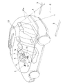
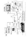
図1は、本発明の実施の第1形態としての駐車アシストシステムの概略的な構成を示す。本実施形態の駐車アシストシステムは、車両1の運転者が、ステアリング1aやシフトレバー1bを操作して、駐車場2で適切な位置に駐車することができるような支援を行う。駐車場2には、車両1の駐車用のスペースを、たとえば白線3などによって表示している。本実施形態の駐車アシストシステムでは、車両1が後進で駐車場2の所定の駐車スペースに駐車しようとするときに、情報ディスプレイ4に車両1の後方画像を表示し、また進行予測曲線5を合せて表示して運転者に対する支援を行う。情報ディスプレイ4に表示する画像は、車両1に搭載される電子制御ユニット(以下、「ECU」と略称することがある)の1つとしての駐車アシストECU6によって作成される。
FIG. 1 shows a schematic configuration of a parking assist system as a first embodiment of the present invention. The parking assist system of the present embodiment provides assistance so that the driver of the
駐車アシストECU6は、車両1の運転者のステアリング操作を、ステアリングの角変位量を検出するステアリング角センサ7の出力として入力し、車両1が後進することは変速機のシフトレバーの位置を検出するシフト位置センサ8からの出力として入力する。シフト位置センサ8は、シフトレバーが後進用のRポジションに操作されると、バックランプを点灯させるスイッチ(以下、「SW」と略称することがある)であるバックランプSWをONにする信号を出力する。駐車アシストECU6は、ステアリング角センサ7およびシフト位置センサ8からの出力に基づいて予測する進行予測曲線5が、白線3からはみ出すようなときには、スピーカ9を介して警報を発し、運転者の注意を促す。車両1の後方の駐車場2の画像は、カメラユニット10によって撮像される。カメラユニット10は、視野10aが駐車場2を向くように、車両1の後部上方に装着される。
The
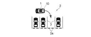
図2は、図1の駐車アシストシステムで車両1が後進しながら駐車場2の白線3で示される駐車スペースに進入しようとしている状態を示す。車両1の後部に取付けられているカメラユニット10は視野10a内の画像を撮像する。この視野10aは、車両1の運転者にとっては、死角となる部分を多く含む。駐車アシストECU6は、カメラユニット10からのNTSC方式の映像信号と、ステアリング角センサ7からのステアリング角の操作に対応するパルスと、シフト位置センサ8からのバックランプSW信号とに応答し、情報ディスプレイ4に対して車両1の進行予測曲線の表示と、クリアランスガイドとを行う。なお、カメラユニット10の撮像方向や撮像倍率が可変する構成の場合は、カメラユニット10の撮像方向(カメラユニット10の角度を検出する角度センサ出力)およびカメラユニット10の撮像倍率(カメラユニット10のレンズ位置を検出するセンサ出力)も進行予測曲線の表示のデータに用いられる。クリアランスガイドは、車両1の進行予測曲線に従って駐車するときに予想される駐車位置を表示し、白線3の画像との間にどの程度のクリアランスが生じるかを情報ディスプレイ4で確認可能にする。
FIG. 2 shows a state in which the
情報ディスプレイ4に、駐車場2をカメラユニット10で撮像した実像と、ステアリング角センサ7が検出するステアリング角に応じた進行予測曲線とを重ねて表示することによって、後進時のステアリング操作角や操作量、これらに伴う効果を判りやすく運転者に知らせて、より安全な運転が可能となるように支援することができる。進行予測曲線5は、線で表示することもできるけれども、実際の車両1の大きさに対応する範囲を塗り潰して進行予測曲線5として表示するようにすれば、視覚的に判りやすい表現で表示することができる。特に、図2に示すように、塗り潰しを半透明な状態で行えば、進行予測曲線5の範囲内に含まれる障害物の実像なども表示されて、安全性をさらに高めることができる。
On the
情報ディスプレイ4は、運転者が見やすい位置に配置する。情報ディスプレイ4としては、たとえば液晶表示装置(LCD)などを用いることが好ましい。また画面の大きさはできるだけ大きい方が好ましい。しかしながら、運転席の近くのスペースには限りがあり、大きな画面の情報ディスプレイ4を、駐車アシストシステムに専用に使用することは効率が悪い。そこで、普段はルームミラ代わりに使用し、後進時に駐車アシスト表示を行うことで、運転者の意図に応じた安全運転の支援が可能となる。ナビゲーションシステムでの地図表示や、テレビジョン放送受信の映像表示などに情報ディスプレイ4を用いることもできる。
The
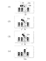
図3は、図1の駐車アシストシステムで情報ディスプレイ4に表示される画像の例を示す。図3の(1)に示すように、運転者がシフトレバー1bを操作して、後進用のするRポジションに移行させると、バックランプを点灯するためにバックランプSWがONとなる。シフト位置センサ8は、バックランプSWをONにする信号を検出し、カメラユニット10の電源を投入して、撮像を開始させる。(2)で、運転者がステアリング1aを操作すると、ステアリング角センサ7がステアリング角を検出し、ステアリング角の変化に対応するパルス信号が駐車アシストECU6に入力される。駐車アシストECU6は、たとえば(3)に示すような進行予測曲線5を情報ディスプレイ4の表示画面上に表示する。(3)に示す状態では、進行予測曲線5が駐車スペースから外れ、車両1が隣接する駐車スペースに駐車中の車両と衝突する恐れが示される。このように、後進後の車両1の予測車両位置が表示されるので、ステアリング操作の方向や操作量を判りやすく表現して、運転の支援を行うことができる。
FIG. 3 shows an example of an image displayed on the
(3)に示す進行予測曲線5の表示を見てこのままではうまく駐車スペースに入りそうにないと判断する運転者がステアリング操作を行い、たとえば(4)に示すような進行予測曲線5の表示が得られると、車両1は駐車場2の白線3間の駐車スペースに進入することが可能であると判断される。車両1が後進し、駐車スペース内に進入していくとともに、カメラユニット10が撮像する画像は変化する。(5)に示すように、画像としては白線3間の駐車位置を中心に表示していても、ステアリング角に基づく進行予測曲線5は、一方側の白線3から外れてしまう。このような表示で、進行方向が好ましくないことが判り、ステアリングを操作して、(6)に示すような進行予測曲線5が得られれば、その方向で後進して、車両1を所定の駐車スペースに正しく駐車することが可能となる。なお、駐車場2で駐車位置を示す車止め2aなどが設けられていれば、その位置を画像処理で認識して、駐車位置を予測することもできる。
The driver who judges that it is unlikely to enter the parking space by looking at the display of the
図4は、図1の駐車アシストシステムでの駐車アシストECU6の画像処理手順を示す。ステップa1から処理を開始し、ステップa2ではシフト位置センサ8によって、車両1の変速機のシフトポジションがバックギア入力状態となっているか否かを判断する。バックランプSWがONでバックギア入力状態のときには、後進用のバック時シフトポジション=Rであり、ステップa3でカメラユニット10のカメラアングルを、視野10aが車両1の後進方向の下方を向くバックポジションとなるように調整する。なお、カメラユニット10の視野角を調整するための構成については、後述する。次にステップa4で、ステアリング角センサ7からステアリング角(θ)を取り込む。ステップa5では、ステアリング角(θ)に対応する進行予測曲線を算出し、ステアリング角(θ)に対応する画像データ(θ)として取り込む。ステップa6では、画像データ(θ)として取り込まれる画像データに対応する描画出力を行う。
FIG. 4 shows an image processing procedure of the parking assist
ステップa2で、バックランプSWがOFFでシフトポジションがバックギア入力状態ではないときには、通常走行時でシフトポジション≠Rと判断される。このときステップa7で、カメラユニット10のカメラアングルを視野10aが後進方向の遠方を向く、通常時のノーマルポジションとなるように変更する。次にステップa8では、ノーマル表示用の画像データを描画出力する。ステップa6またはステップa8が終了すると、ステップa9でカメラユニット10が撮像するカメラ画像に、進行予測曲線の画像データを重ね合せ、ディスプレイ出力として情報ディスプレイ4に対して出力し、ステップa2に戻る。進行予測曲線の表示では、線として表示したり、あるいは塗り潰し、さらには半透明の塗り潰しなどとして表示することができる。また進行予測曲線とともに、たとえば図3の(5)や(6)に示される車止め2aなどの画像を基に、予測駐車位置を算出し、進行予測曲線5とは区別して表示するようにすれば、より判りやすい運転支援を行うことができる。進行予測曲線と、予測駐車位置とは、たとえば色を変えたり、進行予測曲線の方は線で表示し、予測駐車位置の方は塗り潰して表示したりして、両方を合せて判りやすく表示することが好ましい。さらに、進行予測曲線が白線からはみ出したり、他の車両などの障害物に当るようなときには、スピーカ9などから警報を発生することが好ましい。音声合成などで、案内や警告を行うようにすることもできる。
In step a2, when the back lamp SW is OFF and the shift position is not in the back gear input state, it is determined that the shift position is not equal to R during normal traveling. At this time, in step a7, the camera angle of the
図4のステップa3に示すように、カメラアングルをバックポジションに設定する場合には、たとえばモータ21を、基準位置から3秒間逆転させ、ステップa7に示すようなカメラアングルノーマルポジションには、基準位置からモータ21を1秒間正転させるようにして、視野10aの切換えを行う。また、視野角の調整時に、視野角が変化可能な限界の位置をバックポジションやノーマルポジションとして設定しておけば、移動方向に動かなくなるまで駆動し、視野角調整のための構成を簡略化することができる。このように、視野角の位置の検出を不要にすれば、低コスト化も図ることができる。また後進時には、カメラユニット10の視野角を、操作部31によってマニアル操作を行うことができないようにして、マニアル操作による画面角度調整で、運転支援を行う表示内容がずれてしまうのを防止することが好ましい。
As shown in step a3 of FIG. 4, when the camera angle is set to the back position, for example, the
ステップa7のカメラアングルのノーマルポジションでは、たとえばステップa3のカメラアングルバックポジションよりも車両1の後方の遠方に視野10aを向け、後方からの追突を防止するために後方監視を行うように調整することができる。カメラユニット10が後方の画像を撮像し、画像中に含まれる後方車両などの表示位置や大きさによって、後方車両の接近の程度を把握し、追突防止を図ることができる。たとえば、予め表示位置および大きさと、後方車両との距離を簡易的に算出しておき、急激な接近を検出したときには警告して、追突によるむち打ち症などの発生防止に寄与させることができる。
In the normal position of the camera angle in step a7, for example, the
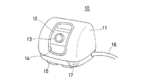
図5は、図1のカメラユニット10の形状を示す。カメラユニット10は、防水性を有するケーシング11内に、ビデオカメラ12が収納される。ビデオカメラ12の撮像用レンズ13が存在する部分は、ケーシング11に透明な窓14が設けられている。ケーシング11内で、ビデオカメラ12は撮像方向を変化させることができる。ケーシング11の底部には、吸着用の磁石15が固定され、図1の車両1の車体の各部に磁力で吸着させて取付けることができる。カメラユニット10からは、コード16が引出され、動作用の電源の供給や、撮像方向の調整、および撮像した画像信号の伝送に使用される。コード16を、車体の表面に添わせる部分には、マグネットクランプなどを設けて保持することもできる。ケーシング11には、集音用のマイクロホン17も設けられる。マイクロホン17はステレオ方式であることが好ましい。方向性をもって音声を収集し、子供や自転車、あるいは他の自動車が接近することを、音としても検知可能にするからである。
FIG. 5 shows the shape of the
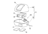
図6は、図5のカメラユニット10を分解した状態を示す。ケーシング11は、上部18と下部19とに分解され、その間にビデオカメラ12およびその撮像方向を変化させる方向変化機構20を収納する。上部18と下部19とを組合わせた状態では、雨水などが内部に浸入しないように密封して、内部を防水状態に保つことができる。
FIG. 6 shows a state where the
図7は、図6の方向変化機構の構成を示す。ケーシング11の下部19にはモータ21が取付けられる。モータ21の出力軸は、ケーシング11の底面にほぼ平行であり、ウォーム歯車22が取付けられる。ウォーム歯車22は下部19の底面から立設される支軸23に装着される平歯車24にモータ21の回転駆動力を伝達する。支軸23には、平歯車24ととともにウォーム歯車25が装着されており、平歯車24に伝達された回転駆動力は、ウォーム歯車25を回転させる。ウォーム歯車25は、ビデオカメラ12の撮像方向を角変位させる角変位軸26の一端に取付けられる平歯車27に回転駆動力を伝達する。角変位軸26は、ケーシング11の下部19の底面にほぼ平行であり、大略的に水平である。平歯車27が、モータ21からの回転駆動力で角変位することによって、ビデオカメラ12の撮像用レンズ13の光軸は、ほぼ水平な角変位軸26の軸線まわりに角変位する。
FIG. 7 shows the configuration of the direction change mechanism of FIG. A
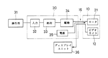
図8は、図5のカメラユニット10の撮像方向を変化させるための概略的な電気的構成を示す。カメラ制御部30は、操作部31から入力される指令に従って、モータ21の回転およびその方向を制御する。操作部31からの指令は、入力回路32に入力され、処理回路33によって指令の内容が解釈される。モータ21を駆動する指令であるときには、処理回路33は駆動回路34を制御して、電源35からの電力を、コード16を介してモータ21に供給し、モータ21を回転させる。ビデオカメラ24が撮像した画像は、ディスプレイユニット36の情報ディスプレイ4としての表示画面で画像として表示される。ディスプレイユニット36は、たとえば車両に搭載されるナビゲーション装置の地図データ表示や、テレビジョン放送の受像用と兼用して用いる。ディスプレイユニット36からカメラユニット10で撮像した画像を見ている操作者は、所望の画像が得られる状態でモータ21の駆動を停止し、撮像方向を一定に保持させる。本実施形態の方向変化機構20は、ウォーム歯車22,25を用いてモータ21からの回転駆動力の伝達を行わせているので、モータ21を停止させれば、ビデオカメラ12にかかる回転モーメントで逆方向に駆動力が伝達することはなく、ビデオカメラ12の撮像方向を保持することができる。
FIG. 8 shows a schematic electrical configuration for changing the imaging direction of the
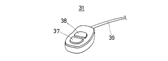
図9は、図8のカメラ制御部30に接続する操作部31の概略的な形状を示す。操作部31は、表面に+回転スイッチ37および−回転スイッチ38が設けられ、+回転スイッチ37を押圧すると、モータ21が一方に回転し、−回転スイッチ38を押せばモータ21が他方に回転する。+回転スイッチ37または−回転スイッチ38の操作結果は、コード39を介して図8の入力回路32に与えられる。操作者は、操作部31を手動で操作して、ディスプレイユニット36の画像を見ながら、適切な対象に撮像方向が向くように調整する。
FIG. 9 shows a schematic shape of the
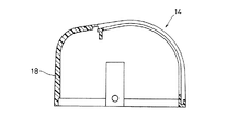
図10は、図6に示すケーシング11の上部18についての正面図を(a)に、平面図を(b)にそれぞれ示す。図11は、図10(b)の切断面線XI−XIから見た断面図を示す。ケーシング11、特にその上部18の形状は、内部のビデオカメラ12が方向変化機構20によって撮像方向を変化させる際に、先端部の撮像用レンズ13が描く軌跡に沿った形状となるように、窓14が形成されている。撮像用レンズ13と窓14との間隔は最小限に抑えられているので、撮像方向が変化しても良好な外部の画像を撮像することができる。さらに窓14の部分は、撥水加工(撥水性の物質でコーティングする)を施し、雨水などが付着しにくくしておく。またこの撥水加工により車両の走行に伴う風で窓14に付着した雨滴が吹き飛ぶという効果もある。これによって、ビデオカメラ12の画像の撮像を良好な状態で行わせることができる。ケーシング11で窓14の他の部分は、できるだけ小さくかつ空気の抵抗とならないような曲面に形成される。またこのようなケーシング11は、軽量の合成樹脂製であり、カメラユニット10全体としても軽量かつ小形に形成される。これによって、磁石15で車両の車載に吸着された状態で、走行中の車両の振動などによって脱落することなく、画像の撮像を行わせることができる。
FIG. 10A is a front view and FIG. 10B is a plan view of the
図12は本発明の実施の第2形態のカメラユニット40の概略的な構成を示す。本実施形態のカメラユニット40は、図5に示すカメラユニット10と大略的に同等であり、対応する部分には同一の参照符を付して重複する説明は省略する。本実施形態のカメラユニット40では、取付機構としてケーシング11の下部19の底面にブラケット41を装着する。ブラケット41はその底面42で車両の車載の任意の部分に、両面粘着テープなどを用いて接合することができる。ブラケット41のケーシング41との取付部43では、取付角度を変えてボルト44およびナット45で締付けて固定することができる。
FIG. 12 shows a schematic configuration of a
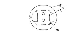
図13は、図12のブラケット41の底面の形状を示す。ブラケット41には、複数の切欠き部分46が形成されているので、接合する車体の曲面形状に合わせて容易に変形させ、両面粘着テープや接着剤などを介して容易に車体に取付けることができる。このような車体への接合方法は、アンテナなどの取付けでも行われおり、充分に信頼性がある実績を有する。なお図5に示すような底部に磁石15を装着したカメラユニット10を、磁力でブラケット41に装着させることもできる。
FIG. 13 shows the shape of the bottom surface of the
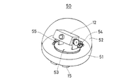
図14は、本発明の実施の第3形態としてのカメラユニット50の概略的な形状を示す。本実施形態のカメラユニット50のケーシング51は、半球状の形状を有し、ビデオカメラ12は、ほぼ水平な軸線まわりばかりではなく、ほぼ鉛直な軸線まわりにも撮像方向を変化させることができる。このため透明な窓52も半球状であり、1箇所にカメラユニット50を設置すれば、多くの方向に撮像方向を変化させて画像を撮像させることができる。ビデオカメラ12の撮像方向を2軸で変化させる方向変化機構53は、たとえば図7に示す方向変化機構20の全体を、さらにほぼ鉛直な軸線まわりに角変位させることによって実現される。
FIG. 14 shows a schematic shape of a
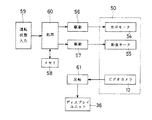
図15は、図14の実施形態でカメラユニット50が撮像する方向を制御するための概略的な電気的構成を示す。図14の方向変化機構53には、撮像方向をほぼ水平な軸線まわりに角変位させる水平モータ54と、ほぼ鉛直な軸線まわりに角変位させる鉛直モータ55とが含まれる。水平モータ54は、図7に示すモータ21と同様な回転力伝達機構で、ビデオカメラ12のほぼ水平な軸線まわりの角変位を行わせる。鉛直モータ55は、図7に示す方向変化機構20の全体をほぼ鉛直な軸線まわりに角変位させる。水平モータ54および鉛直モータ55は、駆動回路56,57によってそれぞれ電気的に駆動される。水平モータ54および鉛直モータ55は、たとえばパルスモータであり、駆動回路56,57が駆動するパルスの数に応じて角変位する。特定の撮像方向に対応するパルスの数は、データとしてメモリ58に記憶される。運転状態入力回路59は、車両の運転状態、たとえば車速、進行方向、ステアリング角度などを表す信号を、車載用の各種電子制御ユニット(ECU)などから入力する。
FIG. 15 shows a schematic electrical configuration for controlling the direction in which the
処理回路60は、運転状態入力回路59に入力される信号で、車両の運転状態を判断し、メモリ58に記憶されているデータを選択して、選択されたデータに従って水平モータ54および鉛直モータ55を駆動し、撮像方向の切換えを運転状態に対応して自動的に行わせることができる。なお、水平モータ54を駆動して撮像方向を90°を越えて変化させ、たとえば前方の撮像から後方の撮像に切換えるようなときに、画像を反転回路61で反転させて表示させる。ディスプレユニット36で表示させると、上下が逆で見にくい画像となる。このような反転回路61を用いて水平な軸線まわりに撮像方向を変化させた画像を反転させる考え方は、図5や図12に示すような1軸の撮像方向の変化を行わせるカメラユニット10,40に対しても適用することができる。
The
図16は、図1の駐車アシストECU6の概略的な電気的構成を示す。駐車アシストECU6内には、全体的な制御を行うデジタル信号プロセッサ(以下、「DSP」と略称する)70が含まれ、バス71を介して制御や信号処理を行う。カメラユニット10からの映像入力としてのNTSC信号は、アンプ+フィルタ回路72に入力され、アナログデジタル変換(以下、「ADC」と略称する)回路73で、アナログ信号からデジタル信号に変換され、フィールドバッファ74に記憶される。アンプ+フィルタ回路74からは、同期分離回路75にも映像入力が与えられ、水平同期や垂直同期用の同期信号が分離されて、DSP70に入力される。DSP70には、ステアリング角センサ7からのステアリング角センサ信号と、シフト位置センサ8からのバックランプSW信号もバッファ76を介して入力される。DSP70は、バス71に接続されるプログラムメモリ77およびデータメモリ78にそれぞれ記憶されているプログラムおよびデータに基づいて動作を行う。
FIG. 16 shows a schematic electrical configuration of the parking assist
DSP70は、入力される映像信号に基づき、白線3などの認識を行ったり、ステアリング角やバックランプSW信号に従う進行予測曲線5の生成を行う。生成された画像は、スイッチ(SW)回路80によって出力が切換え可能なフィールドバッファ81,82に記憶され、SW回路80によって選択されて、デジタルアナログ変換(以下、「DAC」と略称する)回路83からフィルタ+アンプ回路84を介して情報ディスプレイ4に映像出力として与えられる。駐車アシストECU6の全体に対しては、電源85から動作用電力が供給され、リセット回路86からリセット信号が供給され、CLK+分周回路87から動作タイミングを合せるためのクロック信号やそれを分周した信号が供給される。
The
図17は、本実施形態の駐車アシストシステムで後方正面映像を撮像し、車庫入れを支援する状態を示す。車両1が駐車場2で白線3で区画される駐車エリアに、後進して進入し、駐車するまでの運転を、適切に支援することができる。
FIG. 17 shows a state in which a rear front image is captured by the parking assist system of the present embodiment and garage entry is supported. Driving until the
図18は、本発明の実施の第4形態として、図1の駐車アシストシステムの機能を拡張し、縦列駐車にも対応させる状態を示す。撮像用のカメラとしては、図14に示すような水平方向にも視野の変化が可能なカメラユニット50を使用する。バックランプSW信号がONで、かつ左側のウインカランプ88がONになるとき、カメラユニット50の視野を左後方に向けて、駐車エリア89への縦列駐車を支援する。なお、バックランプSWがONでも左側のウインカランプ88がOFFであれば、カメラユニット50を後方正面映像を撮像するように視野を変化させ、図17と同様に車庫入れの駐車支援を行う。
FIG. 18 shows a state in which the function of the parking assist system in FIG. 1 is expanded to support parallel parking as a fourth embodiment of the present invention. As an imaging camera, a
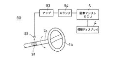
図19は、本発明の実施の第5形態として、ステアリング1aの操作を検出する外付けのステアリング角センサ90の概略的な構成を示す。ステアリング1aの回転軸7aに反射物91を貼付ける。反射物91は、ステアリング1aの回転軸7aの軸線方向に延びる縞模様が光の反射率の変化、またはコントラスト比の変化で形成されている。光学式検出器92は、回転軸7aの角変位を入射光量の変化として検出することができる。光学式検出器92で検出した変化は、アンプ94で電気的に増幅され、カウンタ94で変化の回数を計数する。カウンタ94はアップ・ダウン・カウンタであり、回転の方向によって、計数値を減算または加算して、回転の方向と量とを検出する。カウンタ94の計数値は駐車アシストECU6に入力され、情報ディスプレイ4にステアリング角に応じた進行予測曲線などの表示が行われる。
FIG. 19 shows a schematic configuration of an external
図20は、図19の実施形態で、回転軸7aに貼付けられる反射物91の表面と光学式検出器92との間にクリアランスdを確保する状態を示す。図20(a)に示すように、光学式検出器92は回転軸7aから離して、車両側で支持する。クリアランスdを確保するためには、図20(b)に示すように、焦点距離を大きくしたレンズ95を配置する。回転軸7aには、ステアリング角検出に際して力が加わらないので、ステアリング1aの操作に支障を生じることなく、ステアリング角の検出を行うことができる。
FIG. 20 shows a state in which the clearance d is secured between the surface of the
図21は、本発明の実施の第6形態として、ステアリング1aの操作を検出する外付のステアリング角センサ100の概略的な構成を示す。本実施形態のステアリング角センサ100は、ステアリング1aの回転軸7aを取り囲む筐体部101を備え、その筐体部101を、支持部材102で車両の固定部103に固定する。筐体部101内にセンサを、たとえば回転軸7aの方向と直交するように取付けて固定精度を高めても、筐体部101自体は簡易に車体に取り付けることができる。すなわち、精度を確保し、しかも構造の簡素化によるコスト低減を図ることができる。
FIG. 21 shows a schematic configuration of an external
図22は、本発明の実施の第7形態として、ステアリング角検出のための構成を示す。本実施形態では、反射物91からの反射光を取り込みやすくするため、発光ダイオードなどの発光部92aを設け、赤外光などを照射して、受光部92bでの入射光量を確保している。検出部位周辺の明るさに左右されずに、回転軸7aの角変位を検出することができる。
FIG. 22 shows a configuration for detecting a steering angle as a seventh embodiment of the present invention. In the present embodiment, in order to make it easy to capture the reflected light from the
図23は、本発明の実施の第8形態として、光学的にではなく、電磁的に回転軸7aの角変位を検出する外付けのステアリング角センサ110の概略的な構成を示す。ステアリングの回転軸7aには、磁性体111を固定し、電磁誘導でコイル112に誘起される電気的な信号で、回転軸7aの角変位を検出する。汚れなどの影響を受けにくいので、耐環境性の向上を図ることができる。磁性体111は、たとえば磁化した細長い永久磁石を回転軸7aの軸線方向に向けて、周方向に間隔をあけて並べて固定される。コイル112には、回転軸7aの角変位に対応して、電磁誘導が誘起され、その変動を図19と同様に増幅して計数することができる。
FIG. 23 shows a schematic configuration of an external
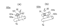
図24は、本発明の実施の第9形態として、回転軸7aの角変位を周囲に伝達して検出する外付けのステアリング角センサ120a,120bの概略的な構成を示す。図24(a)に示すステアリング角センサ120aでは、ステアリングの回転軸7aの回転を、第2の回転軸121aに、弾性ベルト122aおよびプーリ123を介して伝達している。図24(b)に示すステアリング角センサ120bでは、ステアリングの回転軸7aの回転を、第2の回転軸121bに、弾性プーリ122bを介して伝達している。回転の伝達には、歯車などを利用することもできる。第2の回転軸121a,121bの角変位の検出は、たとえば反射物91を貼付けて光学式検出器92で検出するような前述の各種光学的検出法を用いたり、前述の電磁的検出法を用いたり、あるいは第2の回転軸121a,121bにポテンショメータなどを取付けて角変位を直接検出したりすることができる。
FIG. 24 shows a schematic configuration of external
本発明の運転支援装置では、ステアリング角を検出して、ステアリング角に応じて車両1の進路を予測することが重要である。ただし、車両1のステアリング1aでは、回転軸7aが一般に複数回回転可能である。このため、ステアリング1aが特定の方向を向く状態、たとえば正立していても、直進とは限らず、複数回回転させた状態の可能性もある。したがって、直進状態に対応する中央位置を決定することは、特に外付け方式のステアリング角センサ90,100,110,120a,120bでは、困難である。ただし、直進状態となってる頻度が最も高いので、統計的にステアリング操作量の時間的平均から、直進状態に対応する中央位置を学習して求めるようにすると、制御誤差を小さくすることができる。また、電源投入時に、図19のカウンタ94の計数値を0にクリアするような補正手段を設けておけば、ステアリング回転の基準位置である0点を絶対位置として調整することも可能となる。すなわち、電源を遮断した状態で、ステアリング1aを直進状態に調整し、電源を投入すれば調整が完了するからである。
In the driving support device of the present invention, it is important to detect the steering angle and predict the course of the
また、車両1内ではノイズなども多いので、計数値に誤差が混入し、使用中に0点位置がずれるおそれもある。そこで、計数値の最大値と最小値との中央値を0点として記憶し、それまでの最大値より大きい計数値または最小値よりも小さい計数値を検出した場合に、その記憶内容を更新することで、0点の調整やセンサ誤差の補正を行う。さらに、最大値、最小値および中央値を、単独であるいは組合わせて、予め定める個数を平均して求めるようにすれば、ノイズなどによる異常値を検出しても回復が可能なリカバリ効果を持たせることができる。平均は一定数で区切りながら算術平均を行ったり、移動平均として求めたりすることができる。
Further, since there are many noises in the
なお、図19のカウンタ94が計数可能な最大値は、ステアリング切り角の最大量と、ステアリング角センサ7,90,100,110,120a,120bの角度分解能とから算出される最大計数値よりも任意の量だけ余裕を持った計数が可能なようにしておくことが好ましい。計数の誤差やずれがあっても、ステアリング切り角度の検出が可能になるからである。
Note that the maximum value that can be counted by the
図25は、本発明の実施の第10形態としての駐車アシストシステムの概略的な構成を示す。図25の(1)に示すように、運転者がシフトレバー1bを操作して、後進用のRポジションに移行させると、バックランプを点灯するためにバックランプSWがONとなる。(2)で、カメラユニット10や駐車アシストECU130を含む自動駐車システムの電源が投入され、動作を開始する。駐車アシストECU130は、実施の第1形態の駐車アシストECU6の機能を含み、さらに駐車の自動的な支援が可能か否かの判断も行うことができる。
FIG. 25 shows a schematic configuration of a parking assist system as a tenth embodiment of the present invention. As shown in (1) of FIG. 25, when the driver operates the
図25の(3)では、駐車支援可能性を「駐車アシスト」として表示灯などを設けて表示する。駐車支援機能を作動させるための駐車アシストSWを設けておき、運転者が駐車アシストSWをONにして、フットブレーキを解除すると、自動的な駐車支援機能による運転制御が開始される。駐車支援は、図25(4)、(5)に示すように、ステアリング角に応じたカメラアングル自動調整を行いながら進行予測曲線5を情報ディスプレイ4に表示し、車両1を白線3間の駐車エリアに誘導する。図25(6)に示すように、車止め2aなどの障害物を検出したら、制御を停止し、アシスト可能表示も消灯させる。また、図25(7)に示すように、危険などを感じた運転者がフットブレーキ操作を行えば、駐車支援の制御を停止し、アシストが可能であれば、図25(8)に示すように、アシスト可能表示のみを行う。アシストが不可能になっていれば、図25(9)に示すように、単に進行予測曲線5と駐車余地とを情報ディスプレイ4で表示して、実施の第1形態と同様な駐車アシストシステムとして動作する。
In (3) of FIG. 25, the parking support possibility is displayed as “parking assist” by providing an indicator light or the like. When the parking assist SW for operating the parking assist function is provided, and the driver turns on the parking assist SW and releases the foot brake, the driving control by the automatic parking assist function is started. As shown in FIGS. 25 (4) and 25 (5), the parking support displays the
本実施形態では、自動運転制御の安全性を高めるために三重のフェールセーフ機能を設けている。第1は図25(3)、(8)に示すような支援可能表示であり、第2はアシストSWのON操作であり、第3はフットブレーキの解除である。図25(7)に示すように、フットブレーキ操作を行えば、いつでも自動運転を解除することができる。 In the present embodiment, a triple fail-safe function is provided in order to increase the safety of the automatic operation control. The first is a supportable display as shown in FIGS. 25 (3) and (8), the second is an ON operation of the assist SW, and the third is the release of the foot brake. As shown in FIG. 25 (7), the automatic operation can be canceled at any time by performing the foot brake operation.
図26は、本発明の実施の第11形態としての自動駐車システムの概略的な構成を示す。本実施形態の駐車アシストECU140は、図25の駐車アシストECU130と同様に駐車支援可能性を表示しながら、ステアリング制御装置141、スロットル制御装置142、ブレーキ制御装置143に制御データを与え、車両が駐車場2の白線3間の所定位置に自動的に駐車するように制御する。
FIG. 26 shows a schematic configuration of an automatic parking system as an eleventh embodiment of the present invention. The parking assist
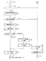
図27は、図26の駐車アシストECU140の制御手順を示す。ステップb1で電源が投入されると、ステップb2でシフト位置センサ8が後進側であるか否かを判断する。バックランプSWがONであることなどから後進と判断されると、ステップb3で白線認識・障害物検出処理が行われ、処理結果はパラメータD0 に保存される。ステップb4では、白線認識および障害物検出が可能であるか否かが判断される。可能であると判断されれば、ステップb5で自動駐車表示がONされ、駐車支援可能であることを示す駐車アシスト可能表示が行われる。次にステップb6では、進行予測曲線5とカメラユニット10が撮像した画像との間での重なり処理が行われる。ステップb7では、重なり部分の有無を判断する。X0 ≠0で重なり部分があると判断されると、ステップb8に移りステアリング角に応じた制御が行われる。
FIG. 27 shows a control procedure of the parking assist
ステップb8では、重なりを回避する方向へのステアリング制御量であるステアリング角θT が演算で求められる。ステップb9では、ステアリング制御装置141をステアリング角がθT となるように制御し、スロットル制御装置142を車両が走行状態となるように制御する。
In step b8, a steering angle θ T that is a steering control amount in a direction to avoid overlap is obtained by calculation. In step b9, the
ステップb7で重なり部分が無しと判断されるとき、またはステップb9の制御が終了したとき、ステップb10でブレーキ制御装置143を制御してのブレーキ制御が行われ、いつでも停止可能なクリープ走行に移行する。実際に車両1を停止させるのは、運転者によるフットブレーキ操作による。
When it is determined in step b7 that there is no overlapping portion, or when the control in step b9 is completed, the brake control is performed by controlling the
ステップb2で後進ではないと判断されるとき、またステップb4で白線・障害物認識ば不可能であると判断されるとき、ステップb12でブレーキ装置143が制御されて車両1は停止する。ステップb13では、「駐車アシスト」などの自動駐車表示が消灯してOFFとなる。ステップb14で制御手順を終了する。
When it is determined at step b2 that the vehicle is not moving backward, or when it is determined at step b4 that white line / obstacle recognition is impossible, the
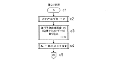
図28は、図27のステップb6でサブルーチンとして行う重なり処理の概略的な手順を示す。ステップc1から処理が開始され、ステップc2ではステアリング角センサ7によるステアリング角θの検出を行う。ステップc3では、ステアリング角θに対する進行予測曲線画像を生成し、駐車アシストデータとしてパラメータD1 に取り込む。ステップc4では、パラメータD0 とD1 とを演算し、共通部分をパラメータX0 に取り込む。ステップc5でサブルーチンを終了し、もとの処理に戻る。
FIG. 28 shows a schematic procedure of the overlapping process performed as a subroutine in step b6 of FIG. Processing is started from step c1, and in step c2, the steering angle θ is detected by the
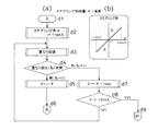
図29は、図27のステップb8でのステアリング制御量θT を演算する処理手順とステアリング角の範囲とを示す。図29(a)に示すように、ステップd1で開始される処理では、ステップd2でまずステアリング角θとして最小値−MAXが設定される。ステップd3では図28に示す重なり処理が行われる。ステップd4では、重なり部分の有無がパラメータX0 が0であるか否かに従って判断される。X0 =0で重なり部分無しと判断されるときには、そのときのθの値をステアリング制御量θT に代入して、ステップd6でもとの処理に戻る。 FIG. 29 shows a processing procedure for calculating the steering control amount θ T in step b8 of FIG. 27 and a range of the steering angle. As shown in FIG. 29 (a), in the process started at step d1, first, at step d2, the minimum value -MAX is set as the steering angle θ. In step d3, the overlapping process shown in FIG. 28 is performed. In step d4, whether the overlapping portion is determined according to whether parameter X 0 is 0. When it is determined that there is no overlapping portion when X 0 = 0, the value of θ at that time is substituted into the steering control amount θ T , and the process returns to step d6.
ステップd4で重なり部分が有ると判断されるときは、ステップd7で、ステアリング角θを1ステップだけ大きくする。ステップd8は、ステアリング角θが最大値+MAXよりも大きくなっているか否かを判断する。ステアリング角θが最大値+MAXよりも大きくないときは、ステップb3に戻る。ステップd8で、ステアリング角θが最大値+MAXを超えていると判断されるときは、制御を終了するため、ステップb9から図27のステップb12に移行し、ブレーキ制御装置143を制御しての車両の停止を行う。なお、ステアリング角は、図29(b)に示すように、正側の最大値が+MAXであり、負側の最小値が−MAXで、中央の0点が直進状態に対応する。中央値は、前述のような学習によって調整することができる。
When it is determined in step d4 that there is an overlapping portion, the steering angle θ is increased by one step in step d7. Step d8 determines whether or not the steering angle θ is larger than the maximum value + MAX. When the steering angle θ is not larger than the maximum value + MAX, the process returns to step b3. When it is determined in step d8 that the steering angle θ exceeds the maximum value + MAX, the control is terminated, so that the process proceeds from step b9 to step b12 in FIG. 27 to control the
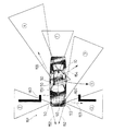
図30は、本発明の実施の第12形態としての自動駐車システムの概略的な動作を示す。本実施形態では、車両1が後進して駐車する際に、ステアリング角の変化に応じてカメラユニット50の視野角を自動的に調整し、進行方向画像を撮像する。図30(1)に示すような駐車用の運転開始後に、ステアリングを直進から左折側に操作すると、後方直進時の視野50aは左後方よりの視野50bに変化する。図30(2)、(3)のように、車両1の駐車運転が進行する過程でも、視野はステアリング角に応じて変化する。図30(4)に示すように、最後に直線的に後退する際には、視野50aは固定される。このような視野の自動的な調整が行われる際には、カメラユニット50の視野角の手動調整は無効にしておくことが好ましい。情報ディスプレイ4上で表示される画像の見え方が違ったり、運転支援情報との整合がとれなくなる可能性があるからである。
FIG. 30 shows a schematic operation of the automatic parking system as the twelfth embodiment of the present invention. In the present embodiment, when the
また、自動駐車システムとしては、駐車のための運転者の操作を、撮像した画像とともに記憶しておき、新たに駐車を行うときに撮像している画像と、記憶されている画像とに類似性があれば、記憶されている運連操作に従って車両1を駐車させるような方式も可能である。車庫や指定駐車場など、繰返して同一の場所に駐車するような場合に、過去の運転操作を自動的に繰返すことができる。
Moreover, as an automatic parking system, the operation of the driver for parking is stored together with the captured image, and the image captured when newly parking is similar to the stored image. If there is, the system which parks the
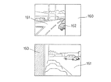
図31は、本発明の実施の第13形態として、車両1の種々の位置のいずれかにカメラユニット10,50を配置し、車両の運転状況に応じて視野を変更し、運転支援を行う状態を示す。(1)に示すように、車両の後方を視野にするカメラユニット10は、車両1の屋根の後部に取付けられ、各実施形態で説明したように、後進して駐車する際の駐車支援に使用することが可能である。しかしながら、通常の走行中には駐車支援の必要性はない。そこで、方向変化機構20を作動させ、カメラユニット10で車両の屋根の上の荷物を監視するように、視野151を変化させる。カメラユニット10の向きが、ほぼ水平な回転軸まわりに90°以上変化して、撮像する画像が後方を撮像する画像と上下方向が逆になるので、図15に示すような反転回路61で電気的に画像の上下方向を反転させれば、図32に示すような画像が得られる。
FIG. 31 shows a state in which the
図31の(2)に示すような前側方の出会い頭事故防止用の撮像を行うカメラユニット50を車両1の前部の両側に配置すれば、通常走行時に両方のカメラユニット50の視野152を前方に向け、進行方向前方の障害物などのステレオ測距に用いることができる。また、(3)に示すような左後方の巻き込み事故防止用に設けるカメラユニット50の視野153を左前方に向けて出会い頭事故防止を図ったり、(4)に示す右後方の進路変更時の接触防止用に設けるカメラユニット50の視野154を屋根の上の荷物監視用に変更したり、(5)に示す屋根の上の荷物監視用に設けるカメラユニット50の視野155を後方監視用に変更したりすることもできる。
If
前側方の出会い頭事故防止用の画像は、車両1が住宅などの駐車場に設けられる塀などの障害物160から道路161に出るときに、図33の(a),(b)に示すように得られる。動きのある画像の認識処理や音などで、接近する車両162などを検出すると、警報を発生したり、ブレーキをかけたりして、安全運転に対する支援を行う。
As shown in FIGS. 33 (a) and 33 (b), the front side encounter accident prevention image is shown when the
以上説明した実施形態では、カメラユニット10,40,50を車両1に搭載しているけれども、車体外の所定位置に設置しておいて、撮像した画像情報を無線で車両1に伝送するような構成でも、画像に基づく運転支援を同様に行うことができる。撮像位置や方向が判れば、相対的な車両1の位置や進行方向なども判り、進行予測曲線などの運転支援情報も、画像に合わせて表示することができる。
In the embodiment described above, the
本発明は、以下の実施の形態が可能である。
(1)車体に装着され、視野角が調整可能なカメラの撮像する画像中に、運転支援情報を追加する情報追加手段と、情報追加手段によって運転支援情報が追加された画像を表示器に表示させる表示手段とを含み、前記カメラは、車両の進行方向を撮像可能で、前記情報追加手段は、ステアリング角センサが検出するステアリング角に応じた車両の通過領域を示す進行予測曲線を、前記運転支援情報として追加することを特徴とする車両の運転支援装置。
The following embodiments are possible for the present invention.
(1) Information adding means for adding driving support information to an image captured by a camera mounted on a vehicle body and having an adjustable viewing angle, and an image in which driving support information is added by the information adding means are displayed on a display. Display means, and the camera is capable of capturing an image of the traveling direction of the vehicle, and the information adding means is configured to display a traveling prediction curve indicating a vehicle passing region corresponding to a steering angle detected by a steering angle sensor. A driving support apparatus for a vehicle, which is added as support information.
車体に装着するカメラが撮像する画像は表示器に表示される。カメラは、車両に装着した状態で視野角が変更可能であるので、一旦車両に取付けた後でも、適切な画像が撮像可能なように、視野角の調整を行うことができる。さらに情報追加手段によって運転支援情報が画像中に追加されるので、車両の運転者は画像とともに表示される運転支援情報に基づいて、車両の運転を安全かつ容易に行うことができる。カメラを、運転者の死角になるような位置の画像を撮像するように配置しておけば、不慮の事故の防止などに寄与させることができる。 An image captured by a camera attached to the vehicle body is displayed on a display. Since the viewing angle of the camera can be changed while being mounted on the vehicle, the viewing angle can be adjusted so that an appropriate image can be taken even after the camera is once mounted. Furthermore, since the driving support information is added to the image by the information adding means, the driver of the vehicle can drive the vehicle safely and easily based on the driving support information displayed together with the image. If the camera is arranged so as to capture an image at a position that becomes a blind spot of the driver, it can contribute to prevention of accidents.
また、視野角の限界位置で所定の視野角が得られるように設定されるので、視野角変更の際には機械的に動かなくなる位置までカメラの視野角変更機構を駆動するだけでよく、矯正のための制御が簡素化され、製造コストの低減も図ることができる。 In addition, since it is set so that a predetermined viewing angle can be obtained at the limit position of the viewing angle, it is only necessary to drive the camera viewing angle changing mechanism to a position where it does not move mechanically when changing the viewing angle. For this reason, the control for this is simplified, and the manufacturing cost can be reduced.
(2)前記カメラは、車体の任意の位置に装着可能であることを特徴とする車両の運転支援装置。 (2) The vehicle driving support apparatus characterized in that the camera can be mounted at an arbitrary position on the vehicle body.
カメラが車体の任意の位置に装着可能であるので、目的に応じて装着場所を変えることができ、少ない台数のカメラで多くの目的に対応させることができる。 Since the camera can be mounted at any position on the vehicle body, the mounting location can be changed according to the purpose, and a small number of cameras can be used for many purposes.
(3)前記情報追加手段は、カメラの視野角の変化に合せて、前記画像の見え方を変化させることを特徴とする車両の運転支援装置。 (3) The vehicle driving support apparatus characterized in that the information adding means changes the appearance of the image in accordance with a change in the viewing angle of the camera.
カメラの視野角を調整すると、情報追加手段がカメラの視野角の変化に応じて画像支援情報の画像中での見え方を変化させるので、カメラが撮像する実像に対して、運転支援情報が違和感なく判りやすく読取ることができるように、画像を表示することができる。 When the viewing angle of the camera is adjusted, the information adding means changes the appearance of the image support information in the image according to the change in the viewing angle of the camera, so the driving support information is uncomfortable with the real image captured by the camera. It is possible to display an image so that it can be easily read.
(4)前記カメラは、機械的な視野角変更の限界位置で、所定の視野角が得られるように設定されることを特徴とする車両の運転支援装置。 (4) The driving support apparatus for a vehicle, wherein the camera is set so as to obtain a predetermined viewing angle at a limit position of mechanical viewing angle change.
視野角の限界位置で所定の視野角が得られるように設定されるので、視野角変更の際には機械的に動かなくなる位置までカメラの視野角変更機構を駆動するだけでよく、矯正のための制御が簡素化され、製造コストの低減も図ることができる。 Since it is set so that a predetermined viewing angle can be obtained at the limit position of the viewing angle, it is only necessary to drive the camera viewing angle changing mechanism to a position where it does not move mechanically when changing the viewing angle. This control is simplified, and the manufacturing cost can be reduced.
(5)前記カメラは、車両の進行方向を撮像可能で、前記情報追加手段は、ステアリング角センサが検出するステアリング角に応じた車両の進行予測曲線を、前記運転支援情報として追加することを特徴とする車両の運転支援装置。 (5) The camera is capable of capturing an image of the traveling direction of the vehicle, and the information adding unit adds a vehicle traveling prediction curve corresponding to a steering angle detected by a steering angle sensor as the driving support information. A vehicle driving support device.
ステアリング角センサによって検出される車両のステアリング角に基づく車両の進行予測曲線を、カメラが撮像する車両の進行方向の画像に追加して表示するので、車両の進行方向についての進行予測を、画像と関連して運転者にとって判りやすく行うことができる。 Since the vehicle travel prediction curve based on the vehicle steering angle detected by the steering angle sensor is displayed in addition to the vehicle travel direction image captured by the camera, the travel prediction for the vehicle travel direction is In connection with this, it can be easily understood by the driver.
(6)前記情報追加手段は、ステアリング角センサが検出するステアリング角に応じた車両の進行予測曲線を、塗りつぶしで表示することを特徴とする車両の運転支援装置。 (6) The vehicle driving support device, wherein the information adding means displays the vehicle progress prediction curve corresponding to the steering angle detected by the steering angle sensor in a solid color.
進行予測は、進行予測曲線に従って車両の通過する範囲にある部分を塗り潰しで重ねて表示するので、視覚的に判りやすい表現で進行予測曲線を表示することができる。 In the progress prediction, the portion in the range through which the vehicle passes is displayed by being overlaid in accordance with the progress prediction curve, so that the progress prediction curve can be displayed in a visually understandable expression.
(7)前記情報追加手段は、前記塗りつぶし表示を半透明となるように行うことを特徴とする車両の運転支援装置。 (7) The vehicle driving support device, wherein the information adding means performs the fill display so as to be translucent.
進行予測曲線と実像との関係が視覚的に判りやすいように、進行予測曲線を半透明の塗りつぶしで表示することができる。 The progress prediction curve can be displayed with a semi-transparent fill so that the relationship between the progress prediction curve and the real image can be easily understood visually.
(8)前記カメラは、車両の後方を撮像可能で、前記情報追加手段は、後進後の予測駐車位置を、前記運転支援情報として追加することを特徴とする車両の運転支援装置。 (8) The driving support apparatus for a vehicle, wherein the camera is capable of capturing an image of the rear of the vehicle, and the information adding unit adds a predicted parking position after reverse travel as the driving support information.
カメラによって車両の後方の画像を撮像し、車両が後進した後で予測される駐車位置を運転者支援情報として表示器に表示するので、狭い駐車場などでも、判りやすい画像表示に基づいて容易に駐車場まで車両を運転することができる。 The camera captures an image behind the vehicle and displays the parking position predicted after the vehicle has moved backward on the display as driver assistance information. Therefore, even in a narrow parking lot, etc., easily based on easy-to-understand image display You can drive the vehicle to the parking lot.
(9)車体に装着され、車体の後方の撮像および視野角の変更が可能なカメラと、カメラの視野角を手動で調整するための調整入力部と、車両の変速機構の設定状態を検出する設定検出部と、設定検出部によって、変速機構が車両の後進側に設定されていると検出されるとき、調整入力部によるカメラの視野角調整を無効にし、予め設定される視野角となるように調整して、カメラが撮像する画像中に、駐車支援情報を追加する情報追加手段と、情報追加手段によって運転支援情報が追加された画像を表示する表示器とを含むことを特徴とする車両の運転支援装置。 (9) A camera that is mounted on the vehicle body and capable of imaging the rear of the vehicle body and changing the viewing angle, an adjustment input unit for manually adjusting the viewing angle of the camera, and a setting state of the transmission mechanism of the vehicle are detected. When the setting detection unit and the setting detection unit detect that the speed change mechanism is set to the reverse side of the vehicle, the adjustment of the viewing angle of the camera by the adjustment input unit is invalidated so that the viewing angle is set in advance. The vehicle includes: an information adding unit that adds parking support information to an image captured by the camera, and a display that displays an image with the driving support information added by the information adding unit. Driving assistance device.
設定検出部が車両の変速機構の設定状態を検出し、車両が後進するように設定されていることが検出されると、調整入力部による手動でのカメラの視野角調整が無効になり、運転支援情報と画像とのずれを防ぐことができる。 When the setting detection unit detects the setting state of the transmission mechanism of the vehicle and detects that the vehicle is set to move backward, manual adjustment of the viewing angle of the camera by the adjustment input unit becomes invalid, and driving A shift between the support information and the image can be prevented.
(10)車両の進行方向を予測する進行予測手段を備え、前記情報追加手段は、前記運転支援情報として、進行予測手段の予測結果に基づく進行予測曲線を生成して追加することを特徴とする車両の運転支援装置。 (10) A progress prediction unit that predicts a traveling direction of the vehicle is provided, and the information addition unit generates and adds a progress prediction curve based on a prediction result of the progress prediction unit as the driving support information. Vehicle driving support device.
表示器にはカメラによって撮像される画像に、進行予測手段が予測する結果に基づき情報追加手段が生成する進行予測曲線が追加されるので、車両の進行方向の予測を運転者が容易に把握することができる。 Since the progress prediction curve generated by the information adding means based on the result predicted by the progress prediction means is added to the image captured by the camera on the display device, the driver can easily grasp the prediction of the traveling direction of the vehicle. be able to.
(11)前記情報追加手段は、前記カメラが撮像する画像に基づく白線認識および障害物検出の処理を行い、前記進行予測曲線が認識された白線または検出された障害物に重ならないように案内する表示を、前記運転支援情報として追加することを特徴とする車両の運転支援装置。 (11) The information adding unit performs white line recognition and obstacle detection processing based on an image captured by the camera, and guides the progress prediction curve so as not to overlap with the recognized white line or the detected obstacle. A driving support apparatus for a vehicle, wherein a display is added as the driving support information.
情報追加手段は、カメラが撮像する画像に基づいて白線認識および障害物検出の処理を行う。白線認識の結果と障害物検出の結果とに基づいて、情報追加手段は、車両の進路が認識された白線や検出された障害物に重ならないように案内するので、車両の運転者は容易に安全な進路に従いながら車両の運転を行うことができる。 The information adding means performs white line recognition and obstacle detection processing based on an image captured by the camera. Based on the result of white line recognition and the result of obstacle detection, the information adding means guides the vehicle path so that it does not overlap with the recognized white line or the detected obstacle. The vehicle can be driven while following a safe path.
(12)前記情報追加手段は、前記カメラが撮像する画像に基づく白線認識および障害物検出の処理を行い、前記進行予測曲線が認識された白線または検出された障害物に重なるとき、警告を行うことを特徴とする車両の運転支援装置。 (12) The information adding unit performs white line recognition and obstacle detection processing based on an image captured by the camera, and issues a warning when the progress prediction curve overlaps the recognized white line or the detected obstacle. A vehicle driving support device characterized by the above.
認識される白線または検出される障害物と、車両の進行予測曲線とが重なるときに、情報追加手段は、車両の進行予測曲線が白線または障害物に重なる旨の警告を行うので、駐車の際の危険などを抑えることができる。 When the recognized white line or the detected obstacle overlaps the vehicle progress prediction curve, the information adding means warns that the vehicle progress prediction curve overlaps the white line or the obstacle. This can reduce the risk of accidents.
(13)前記情報追加手段は、認識された白線または検出された障害物に基づいて駐車枠を認識し、前記警告を、該駐車枠から車両がはみ出さないように行うことを特徴とする車両の運転支援装置。 (13) The vehicle, wherein the information adding unit recognizes a parking frame based on a recognized white line or a detected obstacle, and performs the warning so that the vehicle does not protrude from the parking frame. Driving assistance device.
情報追加手段は、白線または障害物の認識または検出に基づいて駐車枠を認識する。駐車枠から車両がはみ出そうとすると、警告が行われるので、車両の運転者は容易に駐車枠内に車両を進入させて停止させることができる。 The information adding means recognizes the parking frame based on recognition or detection of a white line or an obstacle. When the vehicle is about to protrude from the parking frame, a warning is issued, so that the driver of the vehicle can easily enter the vehicle into the parking frame and stop it.
(14)車体に装着され、視野角の変更が可能なカメラと、車両の進行状態を検知する進行状態検知手段と、進行状態検知手段によって検知される車両の進行状態に対応して、カメラの視野角を変更して調整する視野角調整手段と、カメラが撮像する画像を表示する表示器とを含むことを特徴とする車両の運転支援装置。 (14) A camera mounted on the vehicle body, the viewing angle of which can be changed, a traveling state detecting means for detecting the traveling state of the vehicle, and a camera state corresponding to the traveling state of the vehicle detected by the traveling state detecting means. A vehicle driving support device comprising: a viewing angle adjusting means for changing and adjusting a viewing angle; and a display for displaying an image captured by a camera.
視野角が変更可能なカメラを車体に装着し、進行状態検知手段が車両の進行状態を検知する。視野角調整手段は、進行状態検知手段によって検知される車両の進行状態に対応して、カメラの視野角を調整する。表示器には、車両の進行状態に対応して変更された視野角で、カメラの撮像する画像が表示されるので、運転者が視野角を調整しないでも、車両の進行状態に合せた画像を表示させることができる。 A camera capable of changing the viewing angle is mounted on the vehicle body, and the traveling state detection means detects the traveling state of the vehicle. The viewing angle adjusting unit adjusts the viewing angle of the camera in accordance with the traveling state of the vehicle detected by the traveling state detecting unit. Since the image captured by the camera is displayed on the display device with the viewing angle changed according to the traveling state of the vehicle, an image adapted to the traveling state of the vehicle can be displayed without the driver adjusting the viewing angle. Can be displayed.
(15)前記進行状態検知手段は、車両のステアリング角を検出するステアリング角に応じて、前記カメラの視野角を調整することを特徴とする車両の運転支援装置。 (15) The driving support apparatus for a vehicle, wherein the traveling state detection means adjusts a viewing angle of the camera in accordance with a steering angle for detecting a steering angle of the vehicle.
運転者がステアリング操作を行うと、ステアリング角センサによってステアリング角が検出され、検出されたステアリング角に応じてカメラの視野角が調整される。運転者がステアリング角を変化させているときには、変化するステアリング角に対応してカメラの視野角が調整されるので、ステアリング角の変化で車両の進行方向が変化する方向の画像などを撮像するように視野角を変更すれば、車両の運転に有用な画像を容易に撮像して表示することができる。 When the driver performs the steering operation, the steering angle is detected by the steering angle sensor, and the viewing angle of the camera is adjusted according to the detected steering angle. When the driver changes the steering angle, the viewing angle of the camera is adjusted in accordance with the changing steering angle, so that an image of the direction in which the traveling direction of the vehicle changes due to the change of the steering angle is taken. If the viewing angle is changed, an image useful for driving the vehicle can be easily captured and displayed.
(16)前記進行状態検知手段は、前記ステアリング角センサが検出するステアリング角のセンタ位置と最終回転位置とを学習によって検知することを特徴とする車両の運転支援装置。 (16) The vehicle driving support device, wherein the progress state detecting means detects the center position and the final rotation position of the steering angle detected by the steering angle sensor by learning.
ステアリング角センサが検出するステアリング角は、学習によってセンタ位置と最終回転位置とが検知される。たとえば直進となるステアリング角の状態は統計的に最も多くなる性質があるので、ステアリング角のセンタ位置を容易に検知することができる。最終回転位置は、ステアリング角の変更の限界の位置であり、ステアリング角の変化する最大値として求めることができる。 As for the steering angle detected by the steering angle sensor, the center position and the final rotation position are detected by learning. For example, since the state of the steering angle that goes straight is statistically the largest, the center position of the steering angle can be easily detected. The final rotation position is a limit position for changing the steering angle, and can be obtained as a maximum value at which the steering angle changes.
(17)前記ステアリング角センサは、ステアリングカバーまたはステアリング軸に固定される被検出物と、被検出物の変位を検出する検出器とを含むことを特徴とする車両の運転支援装置。 (17) The vehicle driving support device, wherein the steering angle sensor includes a detected object fixed to a steering cover or a steering shaft, and a detector that detects a displacement of the detected object.
ステアリング角センサを備えていない車両であっても、後付で光学式のステアリング角センサを容易に形成することが可能である。 Even in a vehicle that does not include a steering angle sensor, an optical steering angle sensor can be easily formed later.
(18)前記被検出物は、光学的な反射率またはコントラスト比で移動状態を検出可能で、前記検出器は、光学的に被検出物の移動を検出し、検出強度の変動を計数するとともに、ステアリングの回転の方向に応じて計数値を減算または加算し、ステアリング角の操作方向と操作量とを検出することを特徴とする車両の運転支援装置。 (18) The detection object can detect the movement state by optical reflectance or contrast ratio, and the detector optically detects the movement of the detection object and counts the fluctuation of the detection intensity. A vehicle driving support device that detects a steering angle operation direction and an operation amount by subtracting or adding a count value in accordance with a direction of steering rotation.
後付け可能なステアリング角センサで、ステアリング角の操作方向と操作量とを検出することができ、ステアリングの操作に応じる運転支援を精度よく行うことができる。 The steering angle sensor that can be retrofitted can detect the operation direction and the operation amount of the steering angle, and can provide driving assistance according to the steering operation with high accuracy.
(19)前記検出器は、ステアリング切り角の最大量と角度分解能とから算出される最大計数値より大きな計数値まで計数可能であることを特徴とする車両の運転支援装置。 (19) The vehicle driving support apparatus, wherein the detector can count up to a count value larger than a maximum count value calculated from a maximum amount of steering angle and an angular resolution.
計数値を余裕をもって計数し、計数の誤差やずれがあっても最大値または最小値までの範囲に収め、ステアリング切り角の検出を行うことができる。 The count value is counted with a margin, and even if there is an error or deviation in the count, it is within the range of the maximum value or the minimum value, and the steering angle can be detected.
(20)車体に装着され、視野角の変更が可能なカメラの画像を受信する手段と、車両の進行状態を検知する進行状態検知手段と、進行状態検知手段によって検知される車両の進行状態に対応して、カメラの視野角を変更して調整する視野角調整手段と、カメラが撮像する画像を表示器に表示させる表示手段とを含み、前記視野角調整手段は、ステアリング角センサが検出するステアリング角に応じて、前記カメラの視野角を調整し、前記ステアリング角センサは、ステアリングカバーまたはステアリング軸に固定される被検出物と、
被検出物の変位を検出する検出器とを含み、前記ステアリング角センサ、またはステアリング角センサからの信号を処理する機器に、電源投入時のステアリング角を基準となる中央値として補正する補正回路が設けられることを特徴とする車両の運転支援装置。
(20) A means for receiving an image of a camera mounted on the vehicle body and capable of changing a viewing angle, a progress state detecting means for detecting the progress state of the vehicle, and a vehicle progress state detected by the progress state detecting means. Correspondingly, it includes a viewing angle adjusting means for changing and adjusting the viewing angle of the camera, and a display means for displaying an image captured by the camera on a display, the viewing angle adjusting means being detected by a steering angle sensor. According to a steering angle, the viewing angle of the camera is adjusted, and the steering angle sensor includes a detected object fixed to a steering cover or a steering shaft,
A correction circuit that corrects the steering angle at the time of power-on as a reference median value in the steering angle sensor or a device that processes a signal from the steering angle sensor. A driving support apparatus for a vehicle characterized by being provided.
視野角が変更可能なカメラの画像を受信する手段を車体に装着し、進行状態検知手段が車両の進行状態を検知する。視野角調整手段は、進行状態検知手段によって検知される車両の進行状態に対応して、カメラの視野角を調整する。表示手段は、車両の進行状態に対応して変更された視野角で、カメラの撮像する画像を表示器に表示させるので、運転者が視野角を調整しないでも、車両の進行状態に合せた画像を表示させることができる。 A means for receiving an image of a camera whose viewing angle can be changed is mounted on the vehicle body, and a progress state detecting means detects the progress state of the vehicle. The viewing angle adjusting unit adjusts the viewing angle of the camera in accordance with the traveling state of the vehicle detected by the traveling state detecting unit. The display means displays the image captured by the camera on the display device with the viewing angle changed in accordance with the traveling state of the vehicle, so that the driver can adjust the viewing angle without adjusting the viewing angle. Can be displayed.
また、運転者がステアリング操作を行うと、ステアリング角センサによってステアリング角が検出され、検出されたステアリング角に応じてカメラの視野角が調整される。運転者がステアリング角を変化させているときには、変化するステアリング角に対応してカメラの視野角が調整されるので、ステアリング角の変化で車両の進行方向が変化する方向の画像などを撮像するように視野角を変更すれば、車両の運転に有用な画像を容易に撮像して表示することができる。 When the driver performs a steering operation, the steering angle is detected by the steering angle sensor, and the viewing angle of the camera is adjusted according to the detected steering angle. When the driver changes the steering angle, the viewing angle of the camera is adjusted in accordance with the changing steering angle, so that an image of the direction in which the traveling direction of the vehicle changes due to the change of the steering angle is taken. If the viewing angle is changed, an image useful for driving the vehicle can be easily captured and displayed.
また、ステアリング角センサを備えていない車両であっても、後付で光学式のステアリング角センサを容易に形成することができる。 Even in a vehicle that does not include a steering angle sensor, an optical steering angle sensor can be easily formed later.
また、電源投入時のステアリング軸の位置を調整して、ステアリング軸回転の絶対位置である0点位置を調整することができる。 Further, the position of the steering shaft when the power is turned on can be adjusted to adjust the zero point position, which is the absolute position of the steering shaft rotation.
(21)前記ステアリング角センサ、またはステアリング角センサからの信号を処理する機器に、ステアリング角の計数値の最大値および最小値の中央を基準となる中央値として記憶し、該最大値より大きい計数値または該最小値よりも小さい計数値を検出した場合に、記憶内容を更新する補正回路が設けられることを特徴とする車両の運転支援装置。 (21) In the steering angle sensor or a device that processes a signal from the steering angle sensor, the center of the maximum value and the minimum value of the steering angle is stored as a reference median value, and a value larger than the maximum value is stored. A driving support apparatus for a vehicle, characterized in that a correction circuit is provided for updating stored contents when a numerical value or a count value smaller than the minimum value is detected.
最大値や最小値の記憶内容を、計数値が最大値よりも大きいとき、または最小値よりも小さいときに更新するので、最大値および最小値の中央値として算出されるステアリング角の0点位置を精度よく検出することができる。 Since the stored contents of the maximum value and minimum value are updated when the count value is larger than the minimum value or smaller than the minimum value, the zero point position of the steering angle calculated as the median value of the maximum value and the minimum value Can be detected with high accuracy.
(22)前記最大値、最小値および中央値は、予め定める個数のデータに基づく算術平均または移動平均によって算出されることを特徴とする車両の運転支援装置。 (22) The vehicle driving support device, wherein the maximum value, the minimum value, and the median value are calculated by an arithmetic average or a moving average based on a predetermined number of data.
最大値、最小値および中央値を求める際に、複数個の算術平均または移動平均を求めるので、異常値を検出しても、その影響を軽減してリカバリ効果を得ることができる。 When obtaining the maximum value, the minimum value, and the median value, a plurality of arithmetic averages or moving averages are obtained. Therefore, even if an abnormal value is detected, the influence can be reduced and a recovery effect can be obtained.
(23)前記検出器は、前記ステアリング軸を取り囲む筐体部と、該筐体部を車体に固定して支持する支持部とを備えることを特徴とする車両の運転支援装置。 (23) The driving support apparatus for a vehicle, wherein the detector includes a casing that surrounds the steering shaft, and a support that fixes and supports the casing on the vehicle body.
検出器を容易にステアリング軸に取付けて、しかもその固定精度を高めることができる。精度の確保とともに、構造の簡素化によるコスト低減も図ることができる。 The detector can be easily attached to the steering shaft, and its fixing accuracy can be increased. In addition to ensuring accuracy, cost can be reduced by simplifying the structure.
(24)前記被検出物は、ステアリング軸に固定される反射物であり、前記検出器は、ステアリング軸から間隔を開けて配置される光センサであることを特徴とする車両の運転支援装置。 (24) The vehicle driving support apparatus, wherein the object to be detected is a reflecting object fixed to a steering shaft, and the detector is an optical sensor arranged at a distance from the steering shaft.
ステアリング軸とは離れて角変位を検出することができるので、ステアリングの操作の妨げにならないように、操作の検出を行うことができる。 Since the angular displacement can be detected away from the steering shaft, the operation can be detected so as not to hinder the steering operation.
(25)前記検出器は、前記被検出物に対して光を照射する発光部を備えることを特徴とする車両の運転支援装置。 (25) The vehicle driving support apparatus, wherein the detector includes a light emitting unit that irradiates light to the object to be detected.
検出部位周辺の明るさに左右されずに、ステアリング軸の角変位を検出することができる。 The angular displacement of the steering shaft can be detected regardless of the brightness around the detection region.
(26)前記被検出物は、前記光学的な反射率またはコントラスト比に代えて、磁気的に移動状態を検出可能な磁性体であり、前記検出器は、前記光学的に被検出物の移動を検出する代りに、電磁誘導によって被検出物の移動を検出してステアリング角の変化を検出することを特徴とする車両の運転支援装置。 (26) The detected object is a magnetic body capable of detecting a moving state magnetically instead of the optical reflectance or contrast ratio, and the detector optically moves the detected object. A vehicle driving support device that detects a change in a steering angle by detecting a movement of an object to be detected by electromagnetic induction instead of detecting the vehicle.
光学的な検出に代えて電磁誘導によってステアリング角を検出するので、汚れなどがあっても正確な角度検出が可能で、耐環境性を向上させることができる。 Since the steering angle is detected by electromagnetic induction instead of optical detection, it is possible to accurately detect the angle even if there is dirt, and the environmental resistance can be improved.
(27)前記被検出物は、ステアリング軸の角変位に連動して角変位する軸に固定されることを特徴とする車両の運転支援装置。 (27) The vehicle driving support device, wherein the detected object is fixed to an axis that is angularly displaced in conjunction with an angular displacement of a steering shaft.
ステアリング軸から角変位が伝達される軸の角変位を検出するので、回転数を大きくするなどの変更を行って、ステアリング角を検出することができる。 Since the angular displacement of the shaft to which the angular displacement is transmitted from the steering shaft is detected, the steering angle can be detected by making a change such as increasing the number of rotations.
(28)前記進行状態検知手段は、車両の進行方向を予測して進行予測曲線を生成する予測曲線生成手段を備え、前記視野角調整手段は、予測曲線生成手段が生成する進行予測曲線に応じて、前記カメラの視野角を調整することを特徴とする車両の運転支援装置。 (28) The progress state detection unit includes a prediction curve generation unit that predicts the traveling direction of the vehicle and generates a progress prediction curve, and the viewing angle adjustment unit corresponds to the progress prediction curve generated by the prediction curve generation unit. And a vehicle driving support device for adjusting a viewing angle of the camera.
予測曲線生成手段が車両の進行方向を予測して進行予測曲線を生成する。視野角調整手段は進行予測曲線に応じて、カメラの視野角を調整するので、カメラの撮像する画像が予想される進行方向の画像となり、予想される進行方向の状況を運転者が容易に確認することができる。 A prediction curve generation means generates a progress prediction curve by predicting the traveling direction of the vehicle. The viewing angle adjustment means adjusts the viewing angle of the camera according to the progress prediction curve, so the image captured by the camera becomes an image of the expected traveling direction, and the driver can easily check the situation of the expected traveling direction can do.
(29)前記カメラが撮像する画像および前記進行状態検知手段によって検知される車両の進行状態に基づいて、車両が停止して駐車するように運転制御する駐車制御手段を備えることを特徴とする車両の運転支援装置。 (29) A vehicle comprising parking control means for controlling driving so that the vehicle stops and parks based on an image captured by the camera and a traveling state of the vehicle detected by the traveling state detection means. Driving assistance device.
駐車制御手段によって、カメラが撮像する画像および進行状態検知手段によって検知される車両の進行状態に基づき、車両が停止して駐車するように運転制御が行われる。カメラで、運転者からは直接見ることができないような視野の画像も撮像して、駐車のための運転制御を行うことができるので、安全かつ確実に車両を駐車させることができる。 Based on the image captured by the camera and the traveling state of the vehicle detected by the traveling state detecting unit, the parking control unit performs driving control so that the vehicle stops and parks. Since the camera can capture an image of a field of view that cannot be directly seen by the driver and can perform driving control for parking, the vehicle can be parked safely and reliably.
(30)前記駐車制御手段は、過去の駐車時に行われた運転操作を、前記カメラが撮像した画像と関連させて記憶する記憶手段を備え、該カメラが撮像する画像が記憶手段に記憶されている画像と類似性を有するとき、記憶された運転操作に従って車両を駐車させるように制御することを特徴とする車両の運転支援装置。 (30) The parking control means includes storage means for storing a driving operation performed during past parking in association with an image captured by the camera, and an image captured by the camera is stored in the storage means. And a vehicle driving support device that controls the vehicle to park in accordance with a stored driving operation when there is similarity to the image.
過去に駐車のための運転操作を行うと、カメラの画像とともに記憶手段に記憶され、新たに駐車を行おうとするときにカメラが撮像する画像が記憶手段に記憶されている画像と類似性があれば、つまり過去に同様の状態(同一の場所)で駐車を行っていれば、記憶された運転操作に従って車両を駐車させるように制御するので、繰り返して同じ駐車場所に駐車するような際には、自動的に駐車するような制御を行わせることができる。 When a driving operation for parking is performed in the past, the image stored in the storage unit is stored together with the image of the camera, and the image captured by the camera when newly parking is similar to the image stored in the storage unit. In other words, if you have parked in the same state (same place) in the past, you will control to park the vehicle according to the stored driving operation, so when you park in the same parking place repeatedly It can be controlled to automatically park.
(31)前記駐車制御手段は、前記カメラが撮像する画像に対する白線認識処理および障害物検出処理によって、駐車枠を認識する駐車枠認識手段を備え、駐車枠認識手段によって認識される駐車枠内に駐車するように車両の制御を行うことを特徴とする車両の運転支援装置。 (31) The parking control means includes parking frame recognition means for recognizing a parking frame by white line recognition processing and obstacle detection processing for an image captured by the camera, and the parking control means is within the parking frame recognized by the parking frame recognition means. A vehicle driving support apparatus that controls a vehicle to park.
カメラが撮像する画像に対する白線認識処理および障害物検出処理で、駐車枠認識手段が駐車枠を認識する。駐車制御手段は、駐車枠認識手段によって認識される駐車枠内に駐車するように車両の制御を行うので、駐車枠内に車両を自動的に駐車させることができる。 In the white line recognition process and the obstacle detection process for the image captured by the camera, the parking frame recognition unit recognizes the parking frame. Since the parking control unit controls the vehicle to park in the parking frame recognized by the parking frame recognition unit, the vehicle can be parked automatically in the parking frame.
(32)車体外の所定位置に配置されるカメラと、カメラの撮像する画像を、無線で車両内に伝送する画像伝送手段と、画像伝送手段によって伝送される画像に基づいて、車両の運転制御を行う運転制御手段とを含むことを特徴とする車両の運転支援装置。 (32) A camera disposed at a predetermined position outside the vehicle body, an image transmission unit that wirelessly transmits an image captured by the camera into the vehicle, and vehicle driving control based on the image transmitted by the image transmission unit And a driving control device for performing driving.
車体外の所定位置にカメラを配置し、カメラによって撮像される画像を無線で車両に伝送して、車両の運転制御を伝送される画像に従って行い、車両の運転者が直接見ることができないような視野の画像に基づいて、車両の運転を容易に制御することができる。 A camera is arranged at a predetermined position outside the vehicle body, an image captured by the camera is wirelessly transmitted to the vehicle, and driving control of the vehicle is performed according to the transmitted image, so that the driver of the vehicle cannot directly see Based on the image of the field of view, the driving of the vehicle can be easily controlled.
(33)自動的な駐車支援機能による運転制御装置において、
駐車の自動的な支援が可能か否かを判断する手段と、
判断結果を運転者に表示する手段とを備えることを特徴とする車両の運転制御装置。
(33) In an operation control device with an automatic parking support function,
Means for determining whether or not automatic parking assistance is possible;
A vehicle driving control apparatus comprising: means for displaying a determination result to a driver.
(34)前記運転支援制御装置において、
駐車の自動的な支援が不可能と判断された場合は、マニュアル運転支援用の画面を表示することを特徴とする車両の運転制御装置。
(34) In the driving support control device,
When it is determined that automatic parking assistance is impossible, a driving control device for a vehicle displays a manual driving support screen.
(35)自動的な駐車支援機能による運転制御装置において、
駐車支援機能を作動させるための駐車アシストSWのON操作およびフットブレーキの解除操作に基づいて、自動的な駐車支援機能による運転制御が開始されることを特徴とする車両の運転制御装置。
(35) In an operation control device with an automatic parking support function,
A driving control device for a vehicle, wherein driving control by an automatic parking assist function is started based on an ON operation of a parking assist SW for operating a parking assist function and a release operation of a foot brake.
(36)前記運転制御装置において、
運転者が前記駐車アシストSWをONにして、フットブレーキを解除すると、自動的な駐車支援機能による運転制御が開始されることを特徴とする。
(36) In the operation control device,
When the driver turns on the parking assist SW and releases the foot brake, the driving control by the automatic parking assist function is started.
(37)自動的な駐車支援機能による運転制御装置において、
該運転支援装置が障害物を検出すると自動的な駐車支援機能による運転制御を停止することを特徴とする車両の運転制御装置。
(37) In an operation control device with an automatic parking support function,
A driving control device for a vehicle, wherein when the driving support device detects an obstacle, the driving control by the automatic parking support function is stopped.
(38)自動的な駐車支援機能による運転制御装置において、
運転者がフットブレーキ操作を行えば、駐車支援の制御を停止することを特徴とする車両の運転制御装置。
(38) In an operation control device with an automatic parking assist function,
A vehicle driving control device that stops parking assist control when a driver performs a footbrake operation.
(39)自動的な駐車支援機能とブレーキ制御装置とによる運転制御装置において、
運転者のブレーキ制御によるクリープ走行によって前記運転制御が行われることを特徴とする車両の運転制御装置。
(39) In an operation control device using an automatic parking support function and a brake control device,
The vehicle driving control apparatus according to
(40)自動駐車システムにおいて、
駐車のための運転者の操作を、撮像した画像とともに記憶し、新たに駐車を行うときに撮像している画像と、記憶されている画像とに類似性があれば、記憶されている運転操作に従って車両を駐車させることを特徴とする自動駐車システム。
(40) In an automatic parking system,
The driver's operation for parking is stored together with the captured image, and if there is a similarity between the image captured when newly parking and the stored image, the stored driving operation is stored. An automatic parking system characterized in that the vehicle is parked according to the above.
(41)自動駐車システムにおいて、
駐車のための操作を記憶し、新たに駐車を行うときに、記憶されている運転操作に従って車両を駐車させることを特徴とする自動駐車システム。
(41) In an automatic parking system,
An automatic parking system that stores an operation for parking and parks the vehicle according to the stored driving operation when newly parking.
運転制御装置および自動駐車システムで、画像情報を有効に利用して運転支援を行うことができる。 With the driving control device and the automatic parking system, driving assistance can be performed by effectively using the image information.
1 車両
1a ステアリング
1b シフトレバー
2 駐車場
2a 車止め
3 白線
4 情報ディスプレイ
5 進行予測曲線
6,130,140 駐車アシストECU
7,90,100,110,120a,120b ステアリング角センサ
7a 回転軸
8 シフト位置センサ
9 スピーカ
10,40,50 カメラユニット
10a,10b,50a,151〜155 視野
12 ビデオカメラ
20 方向変化機構
30 カメラ制御部
31 操作部
60 処理回路
61 反転回路
70 DSP
88 ウインカランプ
89 駐車エリア
91 反射物
92 光学式検出器
94 カウンタ
101 筐体部
102 支持部材
103 固定部
111 磁性体
112 コイル
121a,121b 第2の回転軸
141 ステアリング制御装置
142 スロットル制御装置
143 ブレーキ制御装置
DESCRIPTION OF
7, 90, 100, 110, 120a, 120b
88
Claims (22)
前記車両のステアリングの角度を検出するステアリング角検出手段とを含み、
前記情報追加手段は、前記ステアリング角検出手段が検出するステアリング角に応じて変化する前記車両の通過する範囲であって、前記車両の実際の大きさに対応する範囲を示す進行予測曲線を、前記運転支援情報として追加することを特徴とする車両の運転支援装置。 Information adding means for adding driving support information in an image captured by a camera mounted on the vehicle body;
Steering angle detection means for detecting the steering angle of the vehicle,
The information adding means includes a progress prediction curve indicating a range that the vehicle passes through that changes according to a steering angle detected by the steering angle detecting means and that corresponds to an actual size of the vehicle. A driving support apparatus for a vehicle, which is added as driving support information.
前記情報追加手段は、ステアリング角検出手段が検出するステアリング角に応じた車両の進行予測曲線を、前記運転支援情報として追加することを特徴とする請求項1〜4のいずれか1つに記載の車両の運転支援装置。 The camera can image the traveling direction of the vehicle,
The said information addition means adds the vehicle progress prediction curve according to the steering angle which a steering angle detection means detects as said driving assistance information, The any one of Claims 1-4 characterized by the above-mentioned. Vehicle driving support device.
前記情報追加手段は、後進後の予測駐車位置を、前記運転支援情報として追加することを特徴とする請求項1〜7のいずれ1つかに記載の車両の運転支援装置。 The camera can capture the back of the vehicle,
8. The vehicle driving support apparatus according to claim 1, wherein the information adding unit adds a predicted parking position after reverse travel as the driving support information.
車両の進行状態を検知する進行状態検知手段と、
進行状態検知手段によって検知される車両の進行状態に対応して、カメラの視野角を変更して調整する視野角調整手段と、
カメラが撮像する画像を表示する表示器とを含むことを特徴とする請求項1記載の車両の運転支援装置。 A camera that is mounted on the vehicle body and can change the viewing angle;
Traveling state detection means for detecting the traveling state of the vehicle;
A viewing angle adjusting unit that changes and adjusts the viewing angle of the camera in accordance with the traveling state of the vehicle detected by the traveling state detecting unit;
The vehicle driving support apparatus according to claim 1, further comprising a display that displays an image captured by the camera.
ステアリングカバーまたはステアリング軸に固定される被検出物と、
被検出物の変位を検出する検出器とを含むことを特徴とする請求項5、6、10または11のいずれか1つに記載の車両の運転支援装置。 The steering angle detecting means includes
A detected object fixed to the steering cover or the steering shaft;
The vehicle driving support device according to claim 5, further comprising a detector that detects a displacement of the detection object.
前記検出器は、光学的に被検出物の移動を検出し、検出強度の変動を計数するとともに、ステアリングの回転の方向に応じて計数値を減算または加算し、ステアリング角の操作方向と操作量とを検出することを特徴とする請求項12記載の車両の運転支援装置。 The detected object can detect a moving state with an optical reflectance or a contrast ratio,
The detector optically detects the movement of the object to be detected, counts fluctuations in the detected intensity, and subtracts or adds a count value according to the direction of rotation of the steering, thereby operating the steering angle and the operation amount. The vehicle driving support apparatus according to claim 12, wherein:
該筐体部を車体に固定して支持する支持部とを備えることを特徴とする請求項13または14に記載の車両の運転支援装置。 The detector includes a housing portion surrounding the steering shaft;
The vehicle driving support device according to claim 13, further comprising a support portion that fixes and supports the housing portion to the vehicle body.
前記検出器は、ステアリング軸から間隔を開けて配置される光センサであることを特徴とする請求項13または14に記載の車両の運転支援装置。 The detected object is a reflecting object fixed to a steering shaft,
The vehicle driving support device according to claim 13 or 14, wherein the detector is an optical sensor disposed at a distance from a steering shaft.
前記検出器は、前記光学的に被検出物の移動を検出する代りに、電磁誘導によって被検出物の移動を検出してステアリング角の変化を検出することを特徴とする請求項13〜16のいずれか1つに記載の車両の運転支援装置。 The object to be detected is a magnetic body that can detect a moving state magnetically instead of the optical reflectance or contrast ratio,
17. The detector according to claim 13, wherein the detector detects a change in a steering angle by detecting a movement of the detected object by electromagnetic induction instead of detecting the movement of the detected object optically. The driving support device for a vehicle according to any one of the above.
前記視野角調整手段は、予測曲線生成手段が生成する進行予測曲線に応じて、前記カメラの視野角を調整することを特徴とする請求項9記載の車両の運転支援装置。 The progress state detection means includes a prediction curve generation means for predicting the traveling direction of the vehicle and generating a progress prediction curve,
The vehicle driving support apparatus according to claim 9, wherein the viewing angle adjustment unit adjusts the viewing angle of the camera in accordance with a progress prediction curve generated by the prediction curve generation unit.
前記カメラが撮像する画像に対する白線認識処理および障害物検出処理によって、駐車枠を認識する駐車枠認識手段を備え、駐車枠認識手段によって認識される駐車枠内に駐車するように車両の制御を行うことを特徴とする請求項21記載の車両の運転支援装置。 The parking control means includes
A parking frame recognition unit for recognizing a parking frame by white line recognition processing and obstacle detection processing for an image captured by the camera is provided, and the vehicle is controlled to park in the parking frame recognized by the parking frame recognition unit. The vehicle driving support apparatus according to claim 21, wherein:
Priority Applications (1)
| Application Number | Priority Date | Filing Date | Title |
|---|---|---|---|
| JP2009101439A JP2009241925A (en) | 2009-04-17 | 2009-04-17 | Vehicular driving support device |
Applications Claiming Priority (1)
| Application Number | Priority Date | Filing Date | Title |
|---|---|---|---|
| JP2009101439A JP2009241925A (en) | 2009-04-17 | 2009-04-17 | Vehicular driving support device |
Related Parent Applications (1)
| Application Number | Title | Priority Date | Filing Date |
|---|---|---|---|
| JP30120798A Division JP4519957B2 (en) | 1998-10-22 | 1998-10-22 | Vehicle driving support device |
Publications (1)
| Publication Number | Publication Date |
|---|---|
| JP2009241925A true JP2009241925A (en) | 2009-10-22 |
Family
ID=41304322
Family Applications (1)
| Application Number | Title | Priority Date | Filing Date |
|---|---|---|---|
| JP2009101439A Pending JP2009241925A (en) | 2009-04-17 | 2009-04-17 | Vehicular driving support device |
Country Status (1)
| Country | Link |
|---|---|
| JP (1) | JP2009241925A (en) |
Cited By (4)
| Publication number | Priority date | Publication date | Assignee | Title |
|---|---|---|---|---|
| JP2019194091A (en) * | 2015-09-14 | 2019-11-07 | 株式会社ヨコオ | Vehicle roof mounting device |
| CN112298062A (en) * | 2019-07-15 | 2021-02-02 | 径卫视觉科技(上海)有限公司 | Vehicle driving auxiliary equipment and lens angle adjusting device thereof |
| JP2023099013A (en) * | 2022-04-04 | 2023-07-11 | 井関農機株式会社 | tractor |
| FR3141406A1 (en) * | 2022-11-02 | 2024-05-03 | Renault S.A.S | vehicle equipped with two electronic control units with simplified assembly. |
Citations (11)
| Publication number | Priority date | Publication date | Assignee | Title |
|---|---|---|---|---|
| JPS63194044A (en) * | 1987-02-09 | 1988-08-11 | 山口 志郎 | Sludge treatment apparatus |
| JPS6482859A (en) * | 1987-09-25 | 1989-03-28 | Seiko Epson Corp | Automobile-mounted camera fitting construction |
| JPH01111538A (en) * | 1987-10-26 | 1989-04-28 | Toyota Central Res & Dev Lab Inc | Vehicle attitude controller |
| JPH01168538A (en) * | 1987-12-23 | 1989-07-04 | Honda Motor Co Ltd | Vehicle rear view display device |
| JPH07267107A (en) * | 1994-03-30 | 1995-10-17 | Suzuki Motor Corp | Lock detection device for electric power steering system |
| JPH08178679A (en) * | 1994-12-19 | 1996-07-12 | Honda Motor Co Ltd | In-vehicle display device |
| JPH08241493A (en) * | 1995-03-02 | 1996-09-17 | Honda Motor Co Ltd | Calculation and display device for predicted travel path of vehicle |
| JPH0954898A (en) * | 1995-06-09 | 1997-02-25 | Yazaki Corp | Vehicle periphery monitoring device |
| JPH09142210A (en) * | 1995-11-27 | 1997-06-03 | Yazaki Corp | Vehicle periphery monitoring device |
| JPH10175482A (en) * | 1996-10-15 | 1998-06-30 | Isuzu Motors Ltd | Vehicle rear view support device |
| JP2000078566A (en) * | 1998-08-31 | 2000-03-14 | Aisin Seiki Co Ltd | Parking assistance device |
-
2009
- 2009-04-17 JP JP2009101439A patent/JP2009241925A/en active Pending
Patent Citations (11)
| Publication number | Priority date | Publication date | Assignee | Title |
|---|---|---|---|---|
| JPS63194044A (en) * | 1987-02-09 | 1988-08-11 | 山口 志郎 | Sludge treatment apparatus |
| JPS6482859A (en) * | 1987-09-25 | 1989-03-28 | Seiko Epson Corp | Automobile-mounted camera fitting construction |
| JPH01111538A (en) * | 1987-10-26 | 1989-04-28 | Toyota Central Res & Dev Lab Inc | Vehicle attitude controller |
| JPH01168538A (en) * | 1987-12-23 | 1989-07-04 | Honda Motor Co Ltd | Vehicle rear view display device |
| JPH07267107A (en) * | 1994-03-30 | 1995-10-17 | Suzuki Motor Corp | Lock detection device for electric power steering system |
| JPH08178679A (en) * | 1994-12-19 | 1996-07-12 | Honda Motor Co Ltd | In-vehicle display device |
| JPH08241493A (en) * | 1995-03-02 | 1996-09-17 | Honda Motor Co Ltd | Calculation and display device for predicted travel path of vehicle |
| JPH0954898A (en) * | 1995-06-09 | 1997-02-25 | Yazaki Corp | Vehicle periphery monitoring device |
| JPH09142210A (en) * | 1995-11-27 | 1997-06-03 | Yazaki Corp | Vehicle periphery monitoring device |
| JPH10175482A (en) * | 1996-10-15 | 1998-06-30 | Isuzu Motors Ltd | Vehicle rear view support device |
| JP2000078566A (en) * | 1998-08-31 | 2000-03-14 | Aisin Seiki Co Ltd | Parking assistance device |
Cited By (5)
| Publication number | Priority date | Publication date | Assignee | Title |
|---|---|---|---|---|
| JP2019194091A (en) * | 2015-09-14 | 2019-11-07 | 株式会社ヨコオ | Vehicle roof mounting device |
| CN112298062A (en) * | 2019-07-15 | 2021-02-02 | 径卫视觉科技(上海)有限公司 | Vehicle driving auxiliary equipment and lens angle adjusting device thereof |
| JP2023099013A (en) * | 2022-04-04 | 2023-07-11 | 井関農機株式会社 | tractor |
| JP7485143B2 (en) | 2022-04-04 | 2024-05-16 | 井関農機株式会社 | Tractor |
| FR3141406A1 (en) * | 2022-11-02 | 2024-05-03 | Renault S.A.S | vehicle equipped with two electronic control units with simplified assembly. |
Similar Documents
| Publication | Publication Date | Title |
|---|---|---|
| JP4519957B2 (en) | Vehicle driving support device | |
| JP5220797B2 (en) | Vehicle driving support device | |
| JP5310602B2 (en) | Perimeter monitoring system for vehicles | |
| JP6014433B2 (en) | Image processing apparatus, image processing method, and image processing system | |
| JP2000134608A (en) | Rear monitoring device for vehicle | |
| JP2001006097A (en) | Device for supporting driving for vehicle | |
| JP4536889B2 (en) | Vehicle driving support device | |
| JP5182137B2 (en) | Vehicle periphery display device | |
| JP2000127851A5 (en) | Vehicle driving support device and driving control device and automatic parking system | |
| JPH05294183A (en) | On-vehicle monitoring camera device | |
| JP2010064750A (en) | Driving assist device | |
| JP2014072604A (en) | Image processing system, image processing device, image processing method and program | |
| JP2011003117A (en) | Backward visual recognition support system | |
| JP3807330B2 (en) | Vehicle periphery monitoring device | |
| KR20170070459A (en) | Vehicle and method for controlling vehicle | |
| JP4861449B2 (en) | Vehicle driving support device | |
| WO2013144998A1 (en) | Visual recognition assistance apparatus for vehicle | |
| JP2010143577A (en) | Drive assisting device | |
| JP2010076765A (en) | Travel recorder | |
| JP3033390B2 (en) | Vehicle image display device | |
| JP2004001736A (en) | Vehicle-mounted imaging device | |
| JP2012090087A (en) | Driving assist apparatus using vehicle periphery image | |
| JP2004082918A (en) | Vehicle night vision device and rearview mirror | |
| JP4825298B2 (en) | Driving assistance device | |
| JP2009173286A (en) | Driving assistance system of vehicle |
Legal Events
| Date | Code | Title | Description |
|---|---|---|---|
| A977 | Report on retrieval |
Free format text: JAPANESE INTERMEDIATE CODE: A971007 Effective date: 20110701 |
|
| A131 | Notification of reasons for refusal |
Free format text: JAPANESE INTERMEDIATE CODE: A131 Effective date: 20110719 |
|
| A521 | Request for written amendment filed |
Free format text: JAPANESE INTERMEDIATE CODE: A523 Effective date: 20110912 |
|
| A02 | Decision of refusal |
Free format text: JAPANESE INTERMEDIATE CODE: A02 Effective date: 20111227 |