JP2009247687A - Electric kettle - Google Patents
Electric kettle Download PDFInfo
- Publication number
- JP2009247687A JP2009247687A JP2008100579A JP2008100579A JP2009247687A JP 2009247687 A JP2009247687 A JP 2009247687A JP 2008100579 A JP2008100579 A JP 2008100579A JP 2008100579 A JP2008100579 A JP 2008100579A JP 2009247687 A JP2009247687 A JP 2009247687A
- Authority
- JP
- Japan
- Prior art keywords
- hot water
- lid
- heater
- water temperature
- detected
- Prior art date
- Legal status (The legal status is an assumption and is not a legal conclusion. Google has not performed a legal analysis and makes no representation as to the accuracy of the status listed.)
- Withdrawn
Links
Images




Landscapes
- Cookers (AREA)
Abstract
【課題】蓋部が開放された状態を検出したときに、安全性に問題がある状態か否かに応じて、使用者の注意を喚起するためのアラーム報知を行う電気ポットを提供する。
【解決手段】貯湯用の内容器3を備えた容器本体1と、内容器の蓋体2と、湯沸しヒータ4a及び保温ヒータ4bと、内容器内の湯を外部へ給湯するための給湯通路5と、給湯通路を介して内容器内の湯を外部に送り出すための給湯ポンプ6と、内容器中の湯の温度を検出する湯温センサ12と、蓋体の開閉状態を検出する蓋開閉センサ22と、アラーム音を発生させるアラーム報知部52と、湯沸しヒータ及び保温ヒータの通電、湯温センサ及び蓋開閉センサの出力に基づく動作、及びアラーム報知部の動作を制御する制御部41とを備える。制御部は、蓋開閉センサにより蓋体の開放状態が検出され、かつ湯温センサにより湯温が所定値以上であることが検出された場合に、アラーム報知部を動作させる。
【選択図】図1Provided is an electric pot that performs alarm notification for alerting a user according to whether or not there is a problem with safety when detecting a state in which a lid is opened.
A container body 1 having an inner container 3 for hot water storage, a lid 2 of the inner container, a hot water heater 4a and a heat retaining heater 4b, and a hot water supply passage 5 for supplying hot water in the inner container to the outside. A hot water supply pump 6 for sending hot water in the inner container to the outside through the hot water supply passage, a hot water temperature sensor 12 for detecting the temperature of the hot water in the inner container, and a lid opening / closing sensor for detecting the open / closed state of the lid 22, an alarm notification unit 52 that generates an alarm sound, a control unit 41 that controls the operation of the hot water heater and the insulation heater, the operation based on the output of the hot water sensor and the lid opening / closing sensor, and the operation of the alarm notification unit. . A control part operates an alarm alerting | reporting part, when it detects that the open state of a cover body is detected by the lid | cover open / close sensor, and the hot water temperature is more than predetermined value by a hot water temperature sensor.
[Selection] Figure 1
Description
本発明は、電気ポットに関し、特に、貯湯用内容器の開口部の蓋が開放された時における安全性を確保するための構成に関する。 The present invention relates to an electric pot, and more particularly to a configuration for ensuring safety when a lid of an opening of an inner container for hot water storage is opened.
一般に、電気ポットは、内容器内に収容された水を加熱手段である電気ヒータによって加熱沸騰させた後、所定の保温温度で貯湯する。従って、内容器の蓋が開放された状態では熱湯が露出し、使用者にとってやけど等の危険性が存在することになる。そのため、蓋が開放された場合はそのことを検出し、使用者の注意を促すためのアラーム報知、あるいはアラーム表示等の警告を行うことが望ましい。 Generally, in an electric pot, water stored in an inner container is heated and boiled by an electric heater which is a heating means, and then stored at a predetermined temperature. Accordingly, when the lid of the inner container is opened, the hot water is exposed, and there is a risk of burns and the like for the user. For this reason, it is desirable to detect when the lid is opened, and to give a warning such as alarm notification or alarm display for urging the user to pay attention.
また、蓋を開けたとき、蓋に結露していた露が電源プラグに落下して電気的短絡が発生する、という問題が知られている。特許文献1には、この問題を解消するため、蓋部に設置した加熱手段により蓋部に結露することを防ぐ構造が開示されている。更に、蓋部開閉検出手段を設け、水を追加する際に蓋部が開いたことを検出したときには、蓋部の加熱手段をオフにすることも記載されている。すなわち、蓋部が開いた状態では結露のおそれがなく蓋部を加熱する必要がないため、蓋部が開いた状態では蓋部の加熱をオフし、電力の節約を計ることを意図している。
上述のように、特許文献1には、蓋部が開いたことを検出してそれによる制御を行うことは記載されているが、使用者の安全を確保するための注意を促す構成については記載がない。
As described above,
また、電気ポットに水を継ぎ足す作業は日常的に行われるので、その都度、蓋の開放状態を検出してアラーム報知が行われると、使用者にとってかえって煩雑になる。従って、蓋の開放状態を検出したときに、使用者に危害がおよぶ恐れが多い状態か否かに応じて、安全性確保のための対応が取られるようにすることが望ましい。 In addition, since the work of adding water to the electric pot is performed on a daily basis, if an alarm is notified by detecting the open state of the lid each time, it becomes complicated for the user. Therefore, it is desirable that when detecting the open state of the lid, a measure for ensuring safety is taken depending on whether or not there is a high risk of harm to the user.
従って本発明は、蓋部の開放状態を検出した結果に基づき、安全性に問題がある状態か否かに応じて、使用者の注意を喚起するためのアラーム報知を行う機能を有する電気ポットを提供することを目的とする。 Therefore, the present invention provides an electric pot having a function of performing an alarm notification for alerting the user based on the result of detecting the open state of the lid, depending on whether or not there is a problem with safety. The purpose is to provide.
本発明の電気ポットは、上部開口部を有する貯湯用の内容器を備えた容器本体と、前記内容器の前記上部開口部を開閉する蓋体と、前記内容器中を湯沸し時に加熱するための湯沸しヒータと、前記内容器中を保温時に加熱するための保温ヒータと、前記内容器内の湯を外部へ給湯するための給湯通路と、前記給湯通路を介して前記内容器内の湯を外部に送り出すための給湯ポンプと、前記内容器中の湯の温度を検出する湯温センサと、前記蓋体の開閉状態を検出する蓋開閉センサと、アラーム音を発生させるアラーム報知部と、前記湯沸しヒータ及び前記保温ヒータの通電、前記湯温センサ及び前記蓋開閉センサの出力に基づく動作、及び前記アラーム報知部の動作を制御する制御部とを備える。 An electric pot according to the present invention includes a container body having an inner container for hot water storage having an upper opening, a lid for opening and closing the upper opening of the inner container, and heating the inner container during boiling. A hot water heater, a heat retaining heater for heating the inside of the inner container at the time of heat retention, a hot water supply passage for supplying hot water in the inner container to the outside, and the hot water in the inner container through the hot water supply passage to the outside A hot water supply pump for sending out the hot water, a hot water temperature sensor for detecting the temperature of the hot water in the inner container, a lid open / close sensor for detecting the open / closed state of the lid, an alarm notifying unit for generating an alarm sound, and the water heater A controller that controls energization of the heater and the heat retaining heater, an operation based on outputs of the hot water temperature sensor and the lid opening / closing sensor, and an operation of the alarm notification unit.
上記課題を解決するために、前記制御部は、前記蓋開閉センサにより前記蓋体の開放状態が検出され、かつ前記湯温センサにより湯温が所定値以上であることが検出された場合に、前記アラーム報知部を動作させる。 In order to solve the above-described problem, the control unit detects the open state of the lid body by the lid opening / closing sensor and detects that the hot water temperature is equal to or higher than a predetermined value by the hot water temperature sensor. The alarm notification unit is operated.
上記構成の電気ポットによれば、蓋体の開閉だけでなく、湯温との組み合わせで、危険度が高いときだけにアラーム報知が動作する。そのため、蓋部が開放された状態を検出した場合であっても、安全性に応じて適度にアラーム報知が行われ、必要以上の警告で煩雑になることを回避できる。 According to the electric pot having the above-described configuration, the alarm notification is activated only when the degree of danger is high, not only by opening and closing the lid, but also in combination with hot water temperature. Therefore, even when a state where the lid is opened is detected, alarm notification is appropriately performed according to safety, and it is possible to avoid complications due to an unnecessary warning.
本発明の電気ポットは、上記構成を基本として以下のような態様をとることができる。 The electric pot of the present invention can take the following aspects based on the above configuration.
すなわち、前記蓋開閉センサにより前記蓋体の開放状態が検出された場合に、前記湯温センサにより検出される湯温が所定値未満であっても、前記湯沸しヒータまたは前記保温ヒータに通電中である場合は前記アラーム報知部を動作させて表示または報知を行う構成とすることができる。 That is, when the open state of the lid is detected by the lid open / close sensor, even if the hot water temperature detected by the hot water temperature sensor is less than a predetermined value, the hot water heater or the heat retaining heater is energized. In some cases, the alarm notification unit may be operated to display or notify.
また、前記蓋開閉センサにより前記蓋体の開放状態が検出され、かつ前記湯温センサにより湯温が所定値以上であることが検出された場合に、前記アラーム報知部を継続的に動作させ、前記湯温センサにより検出される湯温が、所定値以下になったとき、または所定温度低下したときに、前記アラーム報知部の動作を停止させる構成とすることができる。 Further, when the open state of the lid is detected by the lid open / close sensor and the hot water temperature sensor detects that the hot water temperature is equal to or higher than a predetermined value, the alarm notification unit is continuously operated, When the hot water temperature detected by the hot water temperature sensor becomes equal to or lower than a predetermined value, or when the predetermined temperature decreases, the operation of the alarm notification unit can be stopped.
また、前記蓋開閉センサにより前記蓋体の開放状態が検出された場合に、前記湯沸しヒータまたは前記保温ヒータの通電を停止、またはヒータ出力を低下させる構成とすることができる。 Moreover, when the open state of the lid is detected by the lid open / close sensor, the energization of the water heater or the heat retaining heater is stopped or the heater output is reduced.
この構成において、前記湯沸しヒータまたは前記保温ヒータの通電を停止、またはヒータ出力を低下させた後、前記蓋開閉センサにより前記蓋体の閉鎖状態が検出されたときに、前記湯温センサにより検出される湯温に応じて、前記湯沸しヒータまたは前記保温ヒータの通常状態の通電を開始する構成とすることができる。 In this configuration, after the energization of the hot water heater or the heat retaining heater is stopped or the heater output is reduced, the hot water temperature sensor detects the closed state of the lid body by the lid open / close sensor. Depending on the hot water temperature, it is possible to start energization in the normal state of the water heater or the heat retaining heater.
あるいは、前記湯温センサにより検出される湯温が、所定値以下になったとき、または所定温度低下したときに、前記湯沸しヒータの通常状態の通電を開始する構成とすることができる。 Alternatively, when the hot water temperature detected by the hot water temperature sensor becomes a predetermined value or lower, or when the hot water temperature decreases by a predetermined temperature, energization of the hot water heater in a normal state can be started.
あるいは、前記湯沸しヒータまたは前記保温ヒータの通電を停止、またはヒータ出力を低下させた後、前記蓋開閉センサにより前記蓋体の閉鎖状態が検出されたときに、前記湯温センサにより検出される湯温に関わらず、前記湯沸しヒータの通常状態の通電を開始する構成とすることができる。 Alternatively, after the energization of the hot water heater or the heat retaining heater is stopped or the heater output is reduced, the hot water temperature detected by the hot water temperature sensor is detected when the closed state of the lid is detected by the lid open / close sensor. Regardless of the temperature, the water heater can be energized in a normal state.
また、前記アラーム報知部による報知を停止させる報知停止スイッチを備え、前記アラーム報知部の動作中に前記報知停止スイッチにより報知停止状態にすることが可能であり、前記報知停止状態になった後、前記蓋開閉センサにより前記蓋体の閉鎖状態が検出されたときには、前記報知停止状態が解除される構成とすることができる。 In addition, a notification stop switch for stopping notification by the alarm notification unit, it is possible to be in a notification stop state by the notification stop switch during the operation of the alarm notification unit, and after entering the notification stop state, When the closed state of the lid is detected by the lid open / close sensor, the notification stop state can be released.
以下、添付の図面を参照して、本発明の実施の形態における電気ポットの構成と動作について説明する。まず、各実施の形態に共通である、電気ポットの構造および制御回路について説明する。 Hereinafter, the configuration and operation of an electric pot according to an embodiment of the present invention will be described with reference to the accompanying drawings. First, the structure of the electric pot and the control circuit common to the embodiments will be described.
(電気ポットの構造)
先ず図1〜図3を参照して、実施の形態1における電気ポットの本体および要部の構成について説明する。
(Structure of electric pot)
First, with reference to FIGS. 1-3, the structure of the main body and main part of the electric pot in
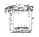
この電気ポットは、図1に示すように、貯湯用の内容器3を備えた容器本体1と、容器本体1の上部側開口部を開閉する蓋体2とを備えている。内容器3の底部に隣接して、湯沸し時の加熱手段である湯沸しヒータ4aと、保温時の加熱手段である保温ヒータ4bとが設けられている。また、内容器3に連通して、貯蔵されている湯を外部へ給湯するための給湯通路5が設けられ、給湯通路5を介して内容器3内の湯を外部に送り出す電動給湯ポンプ6が設けられている。
As shown in FIG. 1, the electric pot includes a
容器本体1は、外側面部を構成する合成樹脂製の筒状の外ケース7と、外ケース7と内容器3とを上部側で一体に結合固定する合成樹脂製の環状の肩部材8と、底面部を構成する合成樹脂製の皿状の底部材9とからなる。
The container
内容器3は、ステンレス製の有底円筒形状の内筒10とステンレス製の円筒形状の外筒11との間に真空断熱空間を設けた、保温性能の高い真空二重構造体からなる。その底部には、外周部を除いて内筒10の底面部のみにより構成された1枚板部3aが形成されている。1枚板部3aは若干上方に高く突出して成形されていて、その下面側には、湯沸しヒータ4aと保温ヒータ4bが取り付けられている。湯沸しヒータ4aと保温ヒータ4bは、例えばワット数の異なる2組の発熱体からなる。
The
内容器3の上端部には、給水口3bが形成されている。内容器3の底部には、サーミスタよりなる湯温センサ12が配置され、内容器3の温度、換言すれば、内容器3内の湯の温度を検出するために使用される。内容器3の内壁面には、内容器3の満水位を表示する凸状の満水位表示部13が形成されている。
A
蓋体2は、合成樹脂製の上板14と、上板14に対して外周縁が結合された合成樹脂製の下板15とからなる。蓋体2は、肩部材8の後部に設けられたヒンジ受け16によりヒンジピン17を介して支持され、上下方向に開閉自在且つ着脱自在である。蓋体2における下板15の下面には、金属製の内カバー部材18が固定されている。内カバー部材18の外周縁には、蓋体2の蓋閉鎖時に内容器3の給水口3bの上面に圧接される耐熱ラバー製のシールパッキン19が設けられている。
The
電動給湯ポンプ6は、給湯通路5の上流端側である内容器3の下部位置に配設されている。電動給湯ポンプ6の吐出口から吐出される湯は、給湯通路5の直管部5aを経て外部への湯注出口5bに導かれる。
The electric hot
操作パネル部20は、各種スイッチ類の操作面や液晶表示パネルを備えている。操作パネル部20の下部には、後述するマイコン制御部や各種スイッチ類や、液晶表示装置の駆動部等を備えたマイコン基板、及び電動給湯ポンプ6の駆動回路や湯沸しヒータ4a、保温ヒータ4bの加熱制御回路、安定化直流電源回路等を備えた電源基板を含む回路基板21が配置されている。
The
図2は、図1の電気ポットの上部を拡大して示す断面図である。図2には、本実施の形態の特徴である、蓋体2の開閉状態を検出する蓋開閉センサ22の構造が示される。蓋開閉センサ22は、容器本体1における蓋体2の周縁に隣接した箇所に配置されたリードスイッチ23と、蓋体2の周縁部におけるリードスイッチ23と対向する箇所に配置された永久磁石24により構成される。蓋体2の開閉に伴い、リードスイッチ23と永久磁石24とが近接、あるいは離間したとき、リードスイッチ23の開閉が行われることにより、蓋体2の解放状態(蓋開放状態)または閉鎖状態(蓋閉鎖状態)が検出される。
FIG. 2 is an enlarged cross-sectional view of the upper portion of the electric pot of FIG. FIG. 2 shows the structure of the lid opening /
蓋開閉センサの他の形態として、容器本体1における蓋体2の周縁に隣接した箇所に突起を設け、蓋体2の開閉に伴い、その突起が伸縮する構成とすることもできる。突起の奥にスイッチを設け、突起の伸縮によりスイッチが開閉されることにより、蓋体2の開閉状態が検出される。
As another form of the lid opening / closing sensor, a protrusion may be provided at a location adjacent to the periphery of the
操作パネル部20には、図3に示すように操作用スイッチとして、給湯スイッチ25、給湯ロック解除スイッチ26、再沸騰スイッチ28、タイマースイッチ29、定量給湯モード選択用の選択スイッチ30、及び保温選択スイッチ31a,31bが設けられている。また、動作表示等のための、給湯ロック解除表示用LED27、再沸騰表示用LED32、保温動作表示用LED33、及び液晶表示部34が設けられている。液晶表示面34には、例えば時刻/時間/湯温設定温度/まほうびん保温等が表示される。さらに、報知停止スイッチ35および報知停止表示用LED36が設けられている。報知停止スイッチ35は、図2に示した蓋開閉センサ22の検出出力に基づく蓋開放状態のアラーム報知をするか否かを選択するためのものである。報知停止表示用LED36は、報知停止スイッチ35による設定が、報知停止状態であるか否かを表示するためのものである。
As shown in FIG. 3, the
この電動給湯型の電気ポットは、連続給湯モードと、定量給湯モードとの2種の給湯モードを備えている。連続給湯モードでは、給湯ロック解除スイッチ26がON操作されていることを条件として、給湯スイッチ25を押し続ける限り、連続的に電動給湯ポンプ6を駆動して湯を注出できる。定量給湯モードでは、仮に給湯ロック解除スイッチ26がON操作されていて、かつ給湯スイッチ25を押し続けても、予じめ設定した所定量の湯を注出すると電動給湯ポンプ6が停止するとともに給湯ロックされる。
This electric hot water supply type electric kettle has two hot water supply modes, a continuous hot water supply mode and a fixed hot water supply mode. In the continuous hot water supply mode, the hot
なお、蓋開放状態が検出されているときは、給湯ロック解除スイッチ26による「ロック解除」操作を受付けず、給湯不能とすることが望ましい。また蓋開放状態で、操作スイッチが押された場合に、さらに注意を促すアラーム報知あるいは表示をさせることが望ましい。
When the lid open state is detected, it is desirable not to accept the “unlock” operation by the hot water supply
(制御回路の構成)
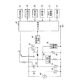
図4は、上記構成の電気ポット本体に設けられた制御回路の構成を示す回路図である。図4において、符号40はAC電源、41はマイコン制御部である。湯沸しヒータ4a、保温ヒータ4b、ポンプ6は、図1に示したものである。給湯スイッチ25は、図2に示したものである。RSは、湯沸しヒータ4a作動用の電源スイッチ(リレースイッチ)、RLは電源スイッチRS駆動用の電源リレー(リレーコイル等リレー駆動回路)である。42は保温ヒータ4b作動用のトライアック、43はトライアック42駆動用のトランジスタである。
(Configuration of control circuit)
FIG. 4 is a circuit diagram showing a configuration of a control circuit provided in the electric pot body having the above configuration. In FIG. 4,
更に、電源電圧のゼロクロス検出回路44、平滑コンデサ45、給湯スイッチ25のONを条件として給湯状態を報知する給湯報知回路46が設けられている。マイコン制御部41には、図示しないが定電圧電源部(本来の動作電源)を介して所定の定電圧が供給される。
Further, a hot water
マイコン制御部41には、さらに、LCD回路47、LED回路48、センサ回路49、SW回路50、クロック発振器51、及びアラーム回路52が入出力ポートを介して接続されている。LCD回路47は、液晶表示部34を駆動するための回路である。LED回路48は、給湯ロック解除表示用LED27、再沸騰表示用LED32、保温動作表示用LED33、報知停止表示用LED36等の各種表示部を駆動するための回路である。センサ回路49は、湯温センサ12、蓋開閉センサ22などの各種センサー部からの出力を受けるための回路である。SW回路50は、給湯ロック解除スイッチ26、再沸騰スイッチ28、タイマースイッチ29、選択スイッチ30、保温選択スイッチ31a、31b等の各種操作部からの出力を受けるための回路である。クロック発振器51は、マイコン作動用のクロック信号を生成する。アラーム回路52は、アラーム音を発生させるための回路である。
Further, an
湯沸しヒータ4aは、例えばマイコン制御部41から湯沸しヒータON信号が出力されると、先ず電源リレーRLが作動され、それに対応して電源スイッチRSがONになることにより駆動される。また、保温ヒータ4bは、マイコン制御部41から保温ヒータON信号が出力されると、トランジスタ43がONになり、トライアック42がトリガーされて駆動される。
For example, when a water heater ON signal is output from the
電動給湯ポンプ6は、そのアース側ライン中に挿入された給湯スイッチ25がON操作されると、給湯報知回路46を介してマイコン制御部41に同給湯スイッチ25のON信号が入力され、それに応じてマイコン制御部41が保温ヒータ4bをOFFにするとともに、マイコン制御部41から所定のデューティー比のパルス電圧信号が出力されて、所定のデューティー比で適切に回転駆動される。
When the hot
以下に、本発明の各実施の形態における、上記構成の電気ポットで蓋体2が開放状態の場合の安全性を確保するための制御動作について説明する。
Below, the control operation | movement for ensuring the safety | security when the
(実施の形態1)
図5は、実施の形態1における、蓋開放状態での安全性を確保するための制御ルーチンを示すフローチャートである。
(Embodiment 1)
FIG. 5 is a flowchart showing a control routine for ensuring safety in the lid open state in the first embodiment.
この制御では、まずステップS1において、湯温センサ12により検出される湯温が保温設定温度以上か否かを判定する。保温設定温度は、例えば90℃に設定される。一般的には90℃が初期設定されていることが多いが、選択温度で98℃、80℃、70℃等に設定可能としてもよい。湯温が保温設定温度以上であれば、ステップS2に進み保温ヒータ4bをオフにし、保温設定温度未満であれば、ステップS3に進み保温ヒータ4bをオンにする。その後、ステップS4に進む。
In this control, first, in step S1, it is determined whether or not the hot water temperature detected by the hot
ステップS4では、蓋開閉センサ22により蓋体2の開放状態が検出されているか否かを判定する。蓋開放状態が検出されていない場合(NO)にはステップS5に進み、アラーム報知をオフにしてスタートに戻る。また、蓋開放状態が検出されている場合(YES)にはステップS6に進み、湯温が所定温度(ここでは50℃)以上か否かを判定する。湯温が50℃以上であれば、ステップS7によりアラーム報知を開始した後、スタートに戻る。湯温が50℃未満であればそのまま、スタートに戻る。
In step S4, it is determined whether or not the open state of the
以上のように本実施の形態によれば、蓋体2が開放状態が検出された場合であっても、更に、湯温が所定値以上であることが検出された場合にのみ、アラーム報知あるいは表示を行う。従って、安全性に問題がある状態か否かに応じて適度に警告を行うことができ、必要以上の警告で煩雑になることを回避できる。
As described above, according to the present embodiment, even when the
なお、蓋体2の開放状態が検出された場合に、湯温が所定値未満であっても、湯沸しヒータ4aまたは保温ヒータ4bに通電中である場合は、アラーム表示または報知を行う構成とすることが望ましい。
When the open state of the
また、蓋開放状態が検出され、アラーム表示・報知を行った場合は、保温ヒータ4bもオフにするか、出力を低下させるようにすることが望ましい。また、所定時間以上、蓋開放状態が続いたら報知するようにすることもできる。あるいは、電源投入後、所定水温以上になっても蓋開放状態が続いたら、報知するようにすることもできる。
Further, when the lid open state is detected and an alarm is displayed / notified, it is desirable to turn off the
(実施の形態2)
図6は、実施の形態2における、蓋開放状態の場合の安全性を確保するための制御ルーチンを示すフローチャートである。この制御では、ステップS1からS4までは実施の形態1と同様の手順で処理を行う。
(Embodiment 2)
FIG. 6 is a flowchart showing a control routine for ensuring safety in the lid open state in the second embodiment. In this control, steps S1 to S4 are processed in the same procedure as in the first embodiment.
ステップS4で、蓋開放状態が検出されていない場合にはステップS5に進み、アラーム報知をオフにしてスタートに戻る。また、蓋開放状態が検出されている場合にはステップS7に進み、アラーム報知を開始する。 If the cover open state is not detected in step S4, the process proceeds to step S5, the alarm notification is turned off, and the process returns to the start. When the lid open state is detected, the process proceeds to step S7, and alarm notification is started.
次にステップS8により、水の継足しが検出されたか否かを判定する。水の継足しは、例えば、湯温センサ12により検出される湯温が、所定値以下になったとき、または所定温度低下したことに基づいて検出する。水の継足し検出の設定例としては、例えば、5秒以内に湯温が10℃以上降下したときに、水の継足しと判断する。水の継足しが検出されない場合は、スタートに戻る。水の継足しが検出された場合は、ステップS9に進み、アラーム報知を停止する。
Next, in step S8, it is determined whether or not water addition has been detected. The addition of water is detected when, for example, the hot water temperature detected by the hot
以上のように本実施の形態によれば、蓋体2の開放状態が検出され、かつ湯温が所定値以上であることが検出された場合に、アラーム表示あるいは報知を継続的に動作させ、水の継足し等により、湯温が所定値以下になったとき、または所定温度低下したときに、アラーム動作を停止させる。それにより、不要なアラーム音を抑制し、騒音を低減することができる。
As described above, according to the present embodiment, when the open state of the
(実施の形態3)
図7は、実施の形態3における、蓋開放状態の場合の安全性を確保するための制御ルーチンを示すフローチャートである。
(Embodiment 3)
FIG. 7 is a flowchart showing a control routine for ensuring safety in the lid open state in the third embodiment.
この制御では、まずステップS10において、保温工程が行われているか否かを判定する。保温工程でなければ、ステップS11に進み、湯沸し工程が行われているか否かを判定する。湯沸し工程でなければ、ステップS12に進み、蓋開放状態か否かを判定する。蓋開放状態でなければ、スタートに戻る。 In this control, first, in step S10, it is determined whether or not a heat retaining process is performed. If it is not a heat retention process, it will progress to step S11 and it will be determined whether the water boiling process is performed. If it is not a kettle process, it will progress to step S12 and it will be determined whether it is a cover open state. If the lid is not open, return to the start.
ステップS10で保温工程であると判定された場合には、ステップS13に進み、湯温センサ12により検出される湯温が保温設定温度以上か否かを判定する。湯温が保温設定温度以上であればステップS14に進み、保温ヒータ4bをオフとし、保温設定温度未満であればステップS15に進み、保温ヒータ4bをオンにした後、ステップS11に進む。
If it is determined in step S10 that the process is a heat retention process, the process proceeds to step S13, and it is determined whether or not the hot water temperature detected by the hot
ステップS11で、湯沸し工程であると判定された場合には、ステップS16に進み、沸騰が完了しているか否かを判定する。沸騰が完了していればステップS17に進み、湯沸しヒータ4aをオフとし、沸騰が完了していなければステップS18に進み、湯沸しヒータ4aをオンにした後、ステップS12に進む。
If it is determined in step S11 that the process is a boiling water process, the process proceeds to step S16, and it is determined whether boiling is completed. If boiling has been completed, the process proceeds to step S17, and the
ステップS12で、蓋開放状態と判定された場合には、ステップS19に進み保温ヒータ4bをオフとし、更にステップS20に進み湯沸しヒータ4aをオフとし、ステップS21に進む。なお、保温ヒータ4b、あるいは湯沸しヒータ4aをオフとするのではなく、ヒータ出力を低下させることで、安全性を確保する構成とすることもできる。ステップS21では、蓋開放状態か否かを判定し、蓋開放状態が続く間は、両ヒータ4a、4bのオフ状態を維持する。ステップS21で蓋閉鎖状態と判定したとき、ステップS22に進む。
If it is determined in step S12 that the lid is open, the process proceeds to step S19, the
ステップS22では、湯温が80℃以上か否かを判定し、80℃未満であれば、ステップS23に進み湯沸し工程をセットする。湯温が80℃以上であれば、ステップS24に進み保温工程をセットする。その後スタートに戻る。なお、湯沸し工程をセットする、とは、湯沸し工程フラグを立てることを意味する。電気ポットの制御工程に含まれる「湯沸し工程」、「保温工程」、「節約タイマー工程」等のどの工程を実行しているのかをメモリーし、制御に利用するためである。 In step S22, it is determined whether or not the hot water temperature is 80 ° C. or higher. If the hot water temperature is lower than 80 ° C., the process proceeds to step S23 to set a boiling water process. If hot water temperature is 80 degreeC or more, it will progress to step S24 and will set a heat retention process. Then return to the start. Note that setting a water heating process means setting a water heating process flag. This is for storing which process, such as the “water heating process”, “warming process”, “saving timer process”, etc. included in the control process of the electric pot is executed and used for control.
以上のように本実施の形態によれば、蓋開閉センサ22により蓋体2の開放状態が検出された場合に、湯沸しヒータ4aまたは保温ヒータ4bの通電を停止、またはヒータ出力を低下させる。それにより、安全性が向上する。
As described above, according to the present embodiment, when the open state of the
また、湯沸しヒータ4aまたは保温ヒータ4bの通電を停止した後、蓋開放状態である間は両ヒータのオフ状態を維持し、蓋体2の閉鎖状態が検出されたときに、湯温センサ12により検出される湯温に応じて、湯沸しヒータ4aまたは保温ヒータ4bの通常状態の通電を開始する。すなわち、上述の例では、湯温が80℃未満であれば湯沸し工程をセットし、80℃以上であれば保温工程をセットする。これにより、蓋体2の開放状態から閉鎖状態に移行したときに、自動的に適切なモードに移行して、利便性を向上させることができる。
In addition, after the energization of the
(実施の形態4)
図8は、実施の形態4における、蓋開放状態の場合の安全性を確保するための制御ルーチンを示すフローチャートである。
(Embodiment 4)
FIG. 8 is a flowchart showing a control routine for ensuring safety in the lid open state in the fourth embodiment.
この制御では、ステップS10からS21までは実施の形態3と同様の手順で処理を行う。また、ステップS21で蓋閉鎖状態と判定したときも、実施の形態3と同様のステップS22からS24の処理を行う。 In this control, steps S10 to S21 are performed in the same procedure as in the third embodiment. Also, when it is determined in step S21 that the lid is closed, the same processes from step S22 to S24 as in the third embodiment are performed.
ステップS21で蓋開放状態と判定したときは、実施の形態3と異なりステップS25に進み、水の継足しが検出されたか否かを判定する。水の継足しは実施の形態2と同様にして検出する。水の継足しが検出されない場合は、ステップS19に戻る。水の継足しが検出された場合は、ステップS26に進み湯沸し工程をセットする。更にステップS27に進み湯沸しヒータ4aをオンとした後、スタートに戻る。
When it is determined in step S21 that the lid is open, the process proceeds to step S25, unlike in the third embodiment, and it is determined whether or not the addition of water is detected. Water addition is detected in the same manner as in the second embodiment. If no water addition is detected, the process returns to step S19. When the addition of water is detected, the process proceeds to step S26, and the water heating process is set. Further, in step S27, the water is heated and the
以上のように本実施の形態によれば、湯沸しヒータ4aまたは保温ヒータ4bの通電を停止、またはヒータ出力を低下させた後、湯温が所定値以下になったとき、または所定温度低下したときに、湯沸しヒータ4aの通常状態の通電を開始する。これにより、水の継足しにより湯温が低下した場合には自動的に沸騰工程に移行し、利便性を向上させることができる。
As described above, according to the present embodiment, when the
(実施の形態5)
図9は、実施の形態5における、蓋開放状態の場合の安全性を確保するための制御ルーチンを示すフローチャートである。この制御では、ステップS10からS21までは実施の形態3と同様の手順で処理を行う。
(Embodiment 5)
FIG. 9 is a flowchart showing a control routine for ensuring safety in the lid open state in the fifth embodiment. In this control, steps S10 to S21 are performed in the same procedure as in the third embodiment.
ステップS21で蓋開放状態と判定したときは、実施の形態3と同様、ステップS19に戻り、両ヒータ4a、4bのオフ状態を維持する。
When it is determined in step S21 that the lid is open, the process returns to step S19, and the
ステップS21で蓋開放状態と判定したときは、実施の形態3と異なりステップS23に進み、湯沸し工程をセットする。更にステップS27に進み湯沸しヒータ4aをオンとした後、スタートに戻る。
When it is determined in step S21 that the lid is open, the process proceeds to step S23, unlike the third embodiment, and a water heating process is set. Further, in step S27, the water is heated and the
このように本実施の形態によれば、湯沸しヒータ4aまたは保温ヒータ4bの通電を停止した後、蓋開閉センサ22により蓋体2の閉鎖状態が検出されたときには、湯温センサ12により検出される湯温に関わらず、湯沸しヒータ4aの通常状態の通電を開始する。それにより、衛生面の安全性を確保することができる。
As described above, according to the present embodiment, when the closed state of the
(実施の形態6)
図10は、実施の形態6における、蓋開放状態の場合の安全性を確保するための制御ルーチンを示すフローチャートである。
(Embodiment 6)
FIG. 10 is a flowchart showing a control routine for ensuring safety in the lid open state in the sixth embodiment.
この制御では、湯沸し工程(ステップS30)、保温工程(ステップS31)及びタイマー工程(ステップS32)のいずれかが行われている場合に、ステップS33では、報知停止スイッチが押されているか否かを判定する。報知停止スイッチが押されていれば、ステップS34に進み報知フラグをオフにした後、ステップS35に進む。報知停止スイッチが押されていなければ、直ちにステップS35に進む。 In this control, when any of the water boiling process (step S30), the heat retaining process (step S31), and the timer process (step S32) is performed, in step S33, it is determined whether or not the notification stop switch is pressed. judge. If the notification stop switch has been pressed, the process proceeds to step S34, the notification flag is turned off, and then the process proceeds to step S35. If the notification stop switch has not been pressed, the process immediately proceeds to step S35.
ステップS35では、蓋体2が閉鎖されているか否かを検出する。蓋体2が閉鎖されている場合には、ステップS36に進み報知フラグをオフにした後、ステップS37に進む。蓋体2が閉鎖されていない場合には、直ちにステップS37に進む。
In step S35, it is detected whether or not the
ステップS37では、蓋体2が開放されているか否かを検出する。開放されていなければ、スタートに戻る。開放されていれば、ステップS38に進み、報知フラグが設定されているか否かを判定する。報知フラグが設定されていれば、ステップS39に進む。報知フラグが設定されていなければ、ステップS40に進む。
In step S37, it is detected whether or not the
ステップS39では、報知フラグがオンか否かを判定する。報知フラグがオフであれば、スタートに戻る。報知フラグがオンであれば、ステップS40に進む。 In step S39, it is determined whether the notification flag is on. If the notification flag is off, the process returns to the start. If the notification flag is on, the process proceeds to step S40.
ステップS40では、湯沸し工程中か否かを判定する。湯沸し工程中であれば、ステップS41に進み、第1アラーム音による報知を行う。湯沸し工程中でなければ、ステップS42に進み、保温工程中か否かを判定する。保温工程中であれば、ステップS43に進み、第2アラーム音による報知を行う。保温工程中でなければ、ステップS44に進み、第3アラーム音による報知を行う。ステップS41、S43、S44の後は、スタートに戻る。 In step S40, it is determined whether or not the water heating process is in progress. If it is in the process of boiling water, it will progress to step S41 and will alert | report by a 1st alarm sound. If it is not in the hot water boiling process, it will progress to step S42 and it will be determined whether it is in a heat retention process. If it is during the heat insulation process, the process proceeds to step S43, and a notification is given by the second alarm sound. If it is not in the heat retention process, the process proceeds to step S44, and a notification by the third alarm sound is performed. After steps S41, S43, and S44, the process returns to the start.
以上のとおり、本実施の形態によれば、アラーム動作中に報知停止スイッチ35により報知停止状態にすることが可能であり、報知停止状態になった後、蓋体2の閉鎖状態が検出されたときには、報知停止状態が解除される。すなわち、アラーム音が不要なときはアラーム報知停止が可能であるが、蓋体2を閉鎖することにより停止がリセットされ、アラーム報知停止の状態が維持されることはなく、常に安全側へシフトする。
As described above, according to the present embodiment, it is possible to set the notification stop state by the
また、第1〜第3アラーム音を準備して、アラーム報知をするときの状態に応じて異なる種類のアラーム音を発生させることができる。 Moreover, the first to third alarm sounds can be prepared, and different types of alarm sounds can be generated according to the state when the alarm is notified.
本発明によれば、蓋が開放されたときに、安全性の程度に応じてアラームを動作させることができ、実用上の適度な範囲で電気ポットの安全性を確保させるために有用である。 According to the present invention, when the lid is opened, an alarm can be operated according to the degree of safety, which is useful for ensuring the safety of the electric pot within a practically appropriate range.
1 容器本体
2 蓋体
3 内容器
3a 1枚板部
3b 給水口
4a 湯沸しヒータ
4b 保温ヒータ
5 給湯通路
5a 直管部
5b 湯注出口
6 電動給湯ポンプ
7 外ケース
8 肩部材
9 底部材
10 内筒
11 外筒
12 温度センサ
13 満水位表示部
14 上板
15 下板
16 ヒンジ受け
17 ヒンジピン
18 内カバー部材
19 シールパッキン
20 操作パネル部
21 回路基板
22 蓋開閉センサ
23 リードスイッチ
24 永久磁石
25 給湯スイッチ
26 給湯ロック解除スイッチ
27 給湯ロック解除表示用LED
28 再沸騰スイッチ
29 タイマースイッチ
30 選択スイッチ
31a、31b 保温選択スイッチ
32 再沸騰表示用LED
33 保温動作表示用LED
34 液晶表示部
35 報知停止スイッチ
36 報知停止表示用LED
40 AC電源
41 マイコン制御部
42 トライアック
43 トライアック駆動用のトランジスタ
44 ゼロクロス検出回路
45 平滑コンデサ
46 給湯報知回路
47 LCD回路
48 LED回路
49 センサ回路
50 SW回路
51 クロック発振器
52 アラーム回路
DESCRIPTION OF
28
33 Insulation LED
34
40
Claims (8)
前記内容器の前記上部開口部を開閉する蓋体と、
前記内容器中を湯沸し時に加熱するための湯沸しヒータと、
前記内容器中を保温時に加熱するための保温ヒータと、
前記内容器内の湯を外部へ給湯するための給湯通路と、
前記給湯通路を介して前記内容器内の湯を外部に送り出すための給湯ポンプと、
前記内容器中の湯の温度を検出する湯温センサと、
前記蓋体の開閉状態を検出する蓋開閉センサと、
アラーム音を発生させるアラーム報知部と、
前記湯沸しヒータ及び前記保温ヒータの通電、前記湯温センサ及び前記蓋開閉センサの出力に基づく動作、及び前記アラーム報知部の動作を制御する制御部とを備え、
前記制御部は、前記蓋開閉センサにより前記蓋体の開放状態が検出され、かつ前記湯温センサにより湯温が所定値以上であることが検出された場合に、前記アラーム報知部を動作させることを特徴とする電気ポット。 A container body including an inner container for hot water storage having an upper opening;
A lid for opening and closing the upper opening of the inner container;
A water heater for heating the inner container during boiling;
A heat retaining heater for heating the inner container during heat retention;
A hot water supply passage for supplying hot water in the inner container to the outside;
A hot water supply pump for sending out the hot water in the inner container to the outside through the hot water supply passage;
A hot water temperature sensor for detecting the temperature of the hot water in the inner container;
A lid opening / closing sensor for detecting an opening / closing state of the lid;
An alarm notification unit for generating an alarm sound;
A controller that controls energization of the hot water heater and the heat retaining heater, an operation based on outputs of the hot water temperature sensor and the lid opening / closing sensor, and an operation of the alarm notification unit,
The control unit operates the alarm notification unit when the open state of the lid is detected by the lid opening / closing sensor and the hot water temperature sensor detects that the hot water temperature is equal to or higher than a predetermined value. An electric kettle characterized by.
前記湯温センサにより検出される湯温が、所定値以下になったとき、または所定温度低下したときに、前記アラーム報知部の動作を停止させる請求項1に記載の電気ポット。 When the lid opening / closing sensor detects the open state of the lid body and the hot water temperature sensor detects that the hot water temperature is equal to or higher than a predetermined value, the alarm notification unit is continuously operated,
The electric kettle according to claim 1, wherein when the hot water temperature detected by the hot water temperature sensor becomes a predetermined value or less, or when the predetermined temperature is lowered, the operation of the alarm notification unit is stopped.
前記アラーム報知部の動作中に前記報知停止スイッチにより報知停止状態にすることが可能であり、
前記報知停止状態になった後、前記蓋開閉センサにより前記蓋体の閉鎖状態が検出されたときには、前記報知停止状態が解除される請求項1に記載の電気ポット。 A notification stop switch for stopping notification by the alarm notification unit;
During the operation of the alarm notification unit, it is possible to make a notification stop state by the notification stop switch,
The electric pot according to claim 1, wherein the notification stop state is canceled when the lid opening / closing sensor detects a closed state of the lid after the notification stop state.
Priority Applications (1)
| Application Number | Priority Date | Filing Date | Title |
|---|---|---|---|
| JP2008100579A JP2009247687A (en) | 2008-04-08 | 2008-04-08 | Electric kettle |
Applications Claiming Priority (1)
| Application Number | Priority Date | Filing Date | Title |
|---|---|---|---|
| JP2008100579A JP2009247687A (en) | 2008-04-08 | 2008-04-08 | Electric kettle |
Publications (1)
| Publication Number | Publication Date |
|---|---|
| JP2009247687A true JP2009247687A (en) | 2009-10-29 |
Family
ID=41308915
Family Applications (1)
| Application Number | Title | Priority Date | Filing Date |
|---|---|---|---|
| JP2008100579A Withdrawn JP2009247687A (en) | 2008-04-08 | 2008-04-08 | Electric kettle |
Country Status (1)
| Country | Link |
|---|---|
| JP (1) | JP2009247687A (en) |
Cited By (5)
| Publication number | Priority date | Publication date | Assignee | Title |
|---|---|---|---|---|
| CN106308485A (en) * | 2015-06-19 | 2017-01-11 | 广东美的生活电器制造有限公司 | Water kettle |
| CN106901598A (en) * | 2015-12-23 | 2017-06-30 | 广东美的生活电器制造有限公司 | A kind of insulating pot |
| CN107788839A (en) * | 2017-12-05 | 2018-03-13 | 杨利云 | A kind of multifunctional safe electric kettle |
| CN112283760A (en) * | 2020-10-29 | 2021-01-29 | 北京蜗牛未来科技有限公司 | an electric water heater |
| KR20210106081A (en) * | 2020-02-20 | 2021-08-30 | 우송대학교 산학협력단 | Portable tumbler with multi-purpose features that emphasize user convenience |
-
2008
- 2008-04-08 JP JP2008100579A patent/JP2009247687A/en not_active Withdrawn
Cited By (7)
| Publication number | Priority date | Publication date | Assignee | Title |
|---|---|---|---|---|
| CN106308485A (en) * | 2015-06-19 | 2017-01-11 | 广东美的生活电器制造有限公司 | Water kettle |
| CN106308485B (en) * | 2015-06-19 | 2018-05-01 | 广东美的生活电器制造有限公司 | Kettle |
| CN106901598A (en) * | 2015-12-23 | 2017-06-30 | 广东美的生活电器制造有限公司 | A kind of insulating pot |
| CN107788839A (en) * | 2017-12-05 | 2018-03-13 | 杨利云 | A kind of multifunctional safe electric kettle |
| KR20210106081A (en) * | 2020-02-20 | 2021-08-30 | 우송대학교 산학협력단 | Portable tumbler with multi-purpose features that emphasize user convenience |
| KR102318513B1 (en) * | 2020-02-20 | 2021-10-27 | 우송대학교 산학협력단 | Portable tumbler with multi-purpose features that emphasize user convenience |
| CN112283760A (en) * | 2020-10-29 | 2021-01-29 | 北京蜗牛未来科技有限公司 | an electric water heater |
Similar Documents
| Publication | Publication Date | Title |
|---|---|---|
| JP2009247687A (en) | Electric kettle | |
| JP2000253999A (en) | Electric hot water storage container | |
| JP4193825B2 (en) | Electric hot water storage container | |
| JP4066958B2 (en) | Electric rice cooker | |
| JP2011254889A (en) | Electric kettle | |
| JP2009268842A (en) | Electric kettle | |
| JP4063101B2 (en) | Electric pressure cooker | |
| JP3506123B2 (en) | Electric hot water storage container | |
| JP3175670B2 (en) | Electric rice cooker | |
| JP4151668B2 (en) | Electric rice cooker | |
| JP5245518B2 (en) | Electric hot water storage container | |
| JP3168984B2 (en) | Electric hot water storage container | |
| JP2005296054A (en) | Electric kettle with tea function | |
| JP3661618B2 (en) | an electronic pot | |
| JP2009254444A (en) | Electric kettle | |
| JP3807398B2 (en) | Electric pot | |
| JP2003125931A (en) | an electronic pot | |
| JP3399417B2 (en) | Electric hot water storage container | |
| JP4218686B2 (en) | Electric pot | |
| JPH08294451A (en) | Electrical pot | |
| JP4618331B2 (en) | Electric pot | |
| JP4842730B2 (en) | Electric water heater | |
| JP2007082736A (en) | Cooking device | |
| JP2004033355A (en) | Electric pot | |
| JP3512009B2 (en) | Liquid insulated container |
Legal Events
| Date | Code | Title | Description |
|---|---|---|---|
| A300 | Withdrawal of application because of no request for examination |
Free format text: JAPANESE INTERMEDIATE CODE: A300 Effective date: 20110705 |