JP2009256902A - Bar arrangement frame for foundation - Google Patents
Bar arrangement frame for foundation Download PDFInfo
- Publication number
- JP2009256902A JP2009256902A JP2008104760A JP2008104760A JP2009256902A JP 2009256902 A JP2009256902 A JP 2009256902A JP 2008104760 A JP2008104760 A JP 2008104760A JP 2008104760 A JP2008104760 A JP 2008104760A JP 2009256902 A JP2009256902 A JP 2009256902A
- Authority
- JP
- Japan
- Prior art keywords
- vertical
- horizontal
- frame
- bar
- reinforcing
- Prior art date
- Legal status (The legal status is an assumption and is not a legal conclusion. Google has not performed a legal analysis and makes no representation as to the accuracy of the status listed.)
- Pending
Links
Images


Landscapes
- Foundations (AREA)
- Reinforcement Elements For Buildings (AREA)
Abstract
Description
本発明は、基礎用配筋枠に関し、特に、建築物のコンクリート基礎を補強する鉄筋等を組み合わせて構成される基礎用配筋枠に関する。 The present invention relates to a reinforcing bar frame for a foundation, and more particularly to a reinforcing bar frame for a foundation constituted by combining reinforcing bars or the like that reinforce a concrete foundation of a building.
従来から、建築物を建設するときには、まずコンクリートを打設して基礎を構築し、その構築した基礎上に土台や柱等を固定する。
このように基礎を構築するとき、まずその基礎を補強するために、その基礎の構築箇所に予め鉄筋による配筋を行うことが多い。この際、鉄筋をその基礎の寸法に合わせて切断し、この寸法に合わせて長さを調整した鉄筋を、基礎を構築する予定の箇所に組み付けて基礎の補強筋を構築する。
Conventionally, when building a building, a concrete is first placed to construct a foundation, and a foundation, a pillar, and the like are fixed on the constructed foundation.
When constructing a foundation in this way, in order to reinforce the foundation, reinforcement is often arranged in advance at the construction site of the foundation in advance. At this time, the reinforcing bars are cut according to the dimensions of the foundation, and the reinforcing bars of the foundation are constructed by assembling the reinforcing bars whose lengths are adjusted according to the dimensions at the locations where the foundation is to be constructed.
しかし、このように基礎の寸法に合った様々な長さの鉄筋を用意するためには、建設現場において鉄筋を1本ずつ寸法を計測して切断作業を行わなければならず、その作業が大変繁雑であった。
また、建設施工業者は、建設現場において必要な鉄筋の長さを確認し、その場で切断を行うことから、切断した後の余りの鉄筋(端材)が大量に生じ、その結果、建材の無駄にしてしまうという問題も生じていた。
However, in order to prepare rebars of various lengths that match the dimensions of the foundation in this way, it is necessary to measure the size of the rebars one by one at the construction site and perform cutting work. It was complicated.
In addition, the construction contractor checks the length of the reinforcing bars necessary at the construction site, and cuts on the spot, resulting in a large amount of excess reinforcing bars (end materials) after cutting. There was also a problem of wasting it.
このような建設現場における鉄筋の切断に関する問題を解決するものの1つとして、特許文献1が開示するところの基礎構築用筋枠が提案されている。
この特許文献1に開示される基礎構築用筋枠は、鉄筋を縦横に直交させて水平面状に組んで構成する筋枠上に、同様に鉄筋を縦横に直交させて構成する立ち上がり筋を垂直に形成するものである。
このように通常は水平面状に組んだ筋枠に対して垂直に立ち上がっている立ち上がり筋を回転して倒せば、その水平面状の筋枠とほぼ同じ平面に重なって全体として平面状になるので、工場で予め予備的に組み合わせておくことができ、そのため、さらに立ち上がり筋を前述の水平面上の鉄筋上を摺動させることによってコンパクトになり、容易に運搬することが可能となる。また、建設現場では、その立ち上がり筋を、立ち上がり時に水平面状の筋枠上を摺動させることにより、従来のような鉄筋の切断作業を行うことなく、立ち上がり筋の位置の調整を容易に行うことができる。また、同時に建材の無駄もなくなる。
In the frame for foundation construction disclosed in Patent Document 1, the reinforcing bars that are formed by crossing the reinforcing bars in the horizontal and vertical directions and the reinforcing bars that are formed by crossing the reinforcing bars in the vertical and horizontal directions vertically To form.
In this way, if you rise and rotate the rising streaks that stand up perpendicularly to the horizontal frame that is usually assembled in a horizontal plane, it overlaps with the same plane as the horizontal plane and becomes flat as a whole. It can be preliminarily combined at the factory, so that the rising bars are further compacted by sliding on the above-mentioned reinforcing bars on the horizontal plane and can be easily transported. In addition, at the construction site, the position of the rising bar can be easily adjusted without sliding the reinforcing bar as in the past by sliding the rising bar on the horizontal frame when rising. Can do. At the same time, building materials are not wasted.
しかしながら、前述の特許文献1に開示される基礎構築用筋枠には、以下のような問題がある。
すなわち、その筋基礎構築用枠を製造する際に、縦横直交するように鉄筋を溶接して組み付ける必要があるが、特許文献1に開示の筋枠では、その縦横に交差する点において縦横の鉄筋の溶接を行っているため、溶接の際の位置決めが困難という施工上の問題が生じる。また、点で溶接しているために、特に、立ち上がり筋の荷重を支持する底部では溶接部分が脱落しやすい等の耐強度に関する問題が生じるおそれもある。
However, the muscle frame for foundation construction disclosed in Patent Document 1 described above has the following problems.
That is, when manufacturing the frame foundation construction frame, it is necessary to weld and assemble the reinforcing bars so as to be orthogonal to each other in the vertical and horizontal directions. However, in the reinforcing frame disclosed in Patent Document 1, the vertical and horizontal reinforcing bars are crossed in the vertical and horizontal directions. Therefore, there is a construction problem that positioning during welding is difficult. In addition, since the welding is performed at points, there may be a problem regarding strength resistance such that the welded portion easily falls off at the bottom portion that supports the load of the rising muscle.
本発明は、上記問題点に鑑みてなされたものであり、収納性及び現場における施工容易性を向上させた配筋枠であって、配筋を組み付ける際の位置決めを容易にするとともに、組み付け後の耐強度の向上を実現する基礎用配筋枠を提供することを目的とする。 The present invention has been made in view of the above-described problems, and is a reinforcing bar frame that improves storage performance and ease of construction in the field, and facilitates positioning when assembling the reinforcing bar, and after mounting. An object of the present invention is to provide a reinforcing bar frame for a foundation that realizes an improvement in the strength resistance of steel.
また、本発明は、設置面に対し水平に配される平面略矩形格子状の水平配筋枠(10)と、水平配筋枠(10)に対し起立して組み付けされる平面略矩形格子状の垂直配筋枠(20)とを有して構成され、建築物の基礎を補強する基礎用配筋枠であって、水平配筋枠(10)は、設置面に対し略水平かつ互いに略平行に所定間隔で配される棒材である水平縦筋材(11)と、水平縦筋材に対し略直交に架設される棒材である水平横筋材(11a,11b,11c)とを有して構成され、垂直配筋枠(20)は、水平配筋枠(10)に対し起立する全体U字形状の垂直縦筋材(21)と、垂直縦筋材(21)に対し略直交に架設される棒材である垂直横筋材(22a,22b,22c)とを有して構成され、垂直縦筋材(21)は、水平縦筋材(11)及び水平横筋材(11a,11b,11c)により区切られて形成される格子目内に遊嵌されることを特徴とする。 Further, the present invention provides a horizontal reinforcing frame (10) in a plane substantially rectangular grid arranged horizontally with respect to the installation surface, and a plane substantially rectangular grid in the form of being installed upright with respect to the horizontal reinforcing frame (10). The vertical reinforcement frame (20) is a foundation reinforcement frame that reinforces the foundation of the building, and the horizontal reinforcement frame (10) is substantially horizontal with respect to the installation surface and substantially mutually. There are horizontal vertical bars (11) which are bars arranged in parallel at predetermined intervals, and horizontal horizontal bars (11a, 11b, 11c) which are bars installed substantially perpendicular to the horizontal vertical bars. The vertical reinforcing bar frame (20) is configured so that the U-shaped vertical vertical reinforcing bar (21) stands up with respect to the horizontal reinforcing bar frame (10) and is substantially orthogonal to the vertical vertical reinforcing bar (21). The vertical vertical bars (22a, 22b, 22c), which are bar members installed on the vertical vertical bars (21), are horizontal vertical bars. 11) and a horizontal lateral stripes material (11a, 11b, 11c) characterized in that it is loosely fitted delimited grid network within which is formed by.
また、本発明によれば、垂直縦筋材(21)は、水平配筋枠(10)に対し起立する少なくとも一対の互いに略平行な棒材である垂直縦筋材起立部(21A)と、少なくとも一対の垂直縦筋材起立部(21A)間に仮設される棒材である垂直縦筋材架設部(21B)とを有して構成され、垂直縦筋材架設部(21B)は、略全面にわたって垂直横筋材(22c)に対し固着されることを特徴とする。 Further, according to the present invention, the vertical vertical bar member (21) includes at least a pair of substantially vertical bars standing upright with respect to the horizontal reinforcing frame (10) and the vertical vertical bar member standing part (21A). And a vertical vertical bar erection part (21B) which is a bar temporarily provided between a pair of vertical vertical bar standing parts (21A). The vertical vertical bar erection part (21B) is substantially It is characterized in that it is fixed to the vertical transverse bar (22c) over the entire surface.
また、本発明によれば、垂直配筋枠(20)は、水平縦筋材(11)の配筋方向に沿って移動可能に係着されるとともに、垂直縦筋材架設部(21B)に固着される垂直横筋材(22c)を軸として水平配筋枠(10)に対し回動可能に組み付けられることを特徴とする。 Further, according to the present invention, the vertical reinforcement frame (20) is movably attached along the reinforcement arrangement direction of the horizontal vertical reinforcement (11) and is attached to the vertical vertical reinforcement installation part (21B). It is characterized by being assembled so as to be rotatable with respect to the horizontal reinforcing frame (10) with the vertical horizontal reinforcing bar (22c) to be fixed as an axis.
また、本発明によれば、垂直配筋枠(20)を回動させると、水平横筋材(11a,11b,11c)及び垂直横筋材(22a,22b,22c)が、水平縦筋材(11)及び垂直縦筋材(21)の外側となるように、水平配筋枠(10)及び垂直配筋枠(20)が略平面を形成して重畳可能に構成されていることを特徴とする。 Further, according to the present invention, when the vertical reinforcing bar frame (20) is rotated, the horizontal horizontal bars (11a, 11b, 11c) and the vertical horizontal bars (22a, 22b, 22c) are converted into the horizontal vertical bars (11). ) And the vertical reinforcing bar frame (21), the horizontal reinforcing bar frame (10) and the vertical reinforcing bar frame (20) are configured so as to overlap each other by forming a substantially flat surface. .
また、本発明によれば、垂直配筋枠(20)を回動させると、水平縦筋材(11)及び垂直縦筋材(21)が、側面視X字状を形成するように、水平配筋枠(10)及び垂直配筋枠(20)が略平面を形成して重畳可能に構成されていることを特徴とする。 Further, according to the present invention, when the vertical reinforcing bar frame (20) is rotated, the horizontal vertical bar member (11) and the vertical vertical bar member (21) are horizontally arranged so as to form an X shape in a side view. The reinforcing bar frame (10) and the vertical reinforcing bar frame (20) are configured to form a substantially flat surface so as to be superposed.
本発明によれば、基礎用配筋枠は、平面略矩形格子状の垂直配筋枠が、設置面に対し水平に配される平面略矩形格子状の水平配筋枠に対して起立して組み付けされて構成され、この垂直配筋枠の全体U字形状の垂直縦筋材は、水平配筋枠の水平縦筋材及び水平横筋材により区切られて形成される格子目内に遊嵌されるので、配筋を組み付ける際の位置決めを容易にするとともに、組み付け後の耐強度を向上させることが可能となる。 According to the present invention, the basic reinforcement frame is erected with respect to the horizontal reinforcement frame of a plane substantially rectangular grid in which the vertical reinforcement frame of the plane substantially rectangular grid is arranged horizontally with respect to the installation surface. The entire vertical U-shaped vertical bar of the vertical bar arrangement frame is loosely fitted in a lattice formed by being divided by the horizontal vertical bar member and the horizontal horizontal bar member of the horizontal bar arrangement frame. Therefore, it is possible to facilitate positioning when assembling the reinforcing bars and to improve the strength resistance after assembling.
<概要>
本発明の実施の形態における基礎用配筋枠は、鉄筋等の筋材を略矩形格子状に枠組みしてなる略平面状の配筋枠を設置面に対して略水平に配し、この配筋枠に対して他の配筋枠を起立するように組み付けて構成されるものである。
この基礎用配筋枠は、予め工場等で組み立てられ、これを平面状に折り畳んだ状態で建築現場へ搬送される。そして、建築物のコンクリート基礎を補強するために、その基礎の構築を予定している位置に予め設置し、折り畳んだ筋枠を立ち上げてコンクリート基礎の補強に使用される。
以下、この基礎用配筋枠の構成、製造方法、折畳方法及び効果等について、詳細に説明する。
<Overview>
The foundation reinforcing frame in the embodiment of the present invention has a substantially flat reinforcing frame formed by arranging reinforcing bars and other reinforcing bars in a substantially rectangular lattice shape, and is arranged substantially horizontally with respect to the installation surface. It is constructed by assembling so that another reinforcing bar frame stands up with respect to the bar frame.
This bar arrangement frame for foundations is assembled in advance at a factory or the like, and is conveyed to the building site in a state where it is folded into a flat shape. And in order to reinforce the concrete foundation of a building, it installs beforehand in the position which the construction of the foundation is planned, raises the folded muscle frame, and is used for reinforcement of a concrete foundation.
Hereinafter, the configuration, the manufacturing method, the folding method, the effect, and the like of this reinforcing bar frame will be described in detail.
<構成>
(1)基礎用配筋枠全体の構成
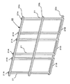
図1は、本発明の実施の形態における基礎用配筋枠の外観を示す斜視図である。
図に示すように、基礎用配筋枠は、鉄筋等の棒状の部材を略矩形格子状に枠組みされてなり基礎の底面部を補強する水平配筋枠10と、同様に略矩形格子状に枠組みされてなりその水平配筋枠10に対して垂直に組み付けされ基礎の垂直壁部を補強する垂直配筋枠20とを有して構成される。
<Configuration>
(1) Configuration of Foundation Reinforcement Frame as a Whole FIG. 1 is a perspective view showing an appearance of a foundation reinforcement frame in the embodiment of the present invention.
As shown in the figure, the reinforcing bar frame for the foundation is formed in a substantially rectangular lattice shape similarly to the horizontal reinforcing
(2)水平配筋枠10の構成
図2は、本発明の実施の形態における水平配筋枠10の外観を示す斜視図である。
また、図3は、本発明の実施の形態における水平配筋枠10の側面図である。
以下、これら図2,3を用いて、本実施の形態における水平配筋枠10の構成について説明する。
(2) Configuration of Horizontal
FIG. 3 is a side view of the horizontal
Hereinafter, the configuration of the horizontal reinforcing
図に示すように、水平配筋枠10は、所定間隔で略平行かつ略水平に配設された複数の水平縦筋材11と、これら複数の水平縦筋材11に対し所定間隔をおいて略直交に架け渡される複数の水平横筋材12a,12b,12cとを有して構成される。
これら水平縦筋材11と水平横筋材12a,12b,12cとは、略矩形格子状に組み合わされ、その交差部位は、スポット溶接又は針金・留め付け金具等で固定されている。
なお、以下、説明の便宜上、その水平横筋材12cが架け渡されている側を正面側とし、水平横筋材12aが架け渡されている側を背面側とする。
As shown in the figure, the horizontal reinforcing
The horizontal
Hereinafter, for convenience of explanation, the side on which the horizontal
また、図に示すように、水平縦筋材11に架け渡される水平横筋材12a,12b,12cのうち、水平横筋材12aは、水平縦筋材11の垂直下側に配設される。一方、中間の水平横筋材12b及び正面側の水平横筋材12cは、反対に水平縦筋材11の垂直上側に配設される。
Further, as shown in the figure, among the horizontal
(3)垂直配筋枠20の構成
図4は、本発明の実施の形態における垂直配筋枠20の外観を示す斜視図である。
また、図5は、本発明の実施の形態における垂直配筋枠20の側面図である。
以下、これら図4,5を用いて、本実施の形態における垂直配筋枠20の構成について説明する。
(3) Configuration of Vertical
FIG. 5 is a side view of the vertical reinforcing
Hereinafter, the configuration of the vertical
図に示すように、垂直配筋枠20は、所定間隔で互いに略平行に配設される複数のU字型の垂直縦筋材21と、これら複数の垂直縦筋材21に対し略直交するように所定間隔に互いに略平行に架け渡される複数の垂直横筋材22a,22b,22cとを有して構成される。
これら垂直縦筋材21と垂直横筋材22a,22b,22cとは、略矩形格子状に組み合わされ、その交差部位は、スポット溶接又は針金・留め付け金具等で固定されている。
以上のように構成される垂直配筋枠20は、水平配筋枠10に対し略垂直に組み付けられる。
As shown in the figure, the vertical
The vertical
The vertical
また、図に示すように、その垂直縦筋材21は、互いに平行で水平配筋枠10に対し略垂直に起立する一対の垂直縦筋材起立部21Aと、これら一対の垂直縦筋材起立部21Aの一端の間を架け渡すようにして結合する垂直縦筋材架設部21Bとを有して構成され、全体としてU字型を形成している。
Further, as shown in the figure, the vertical
また、図に示すように、垂直縦筋材21に架け渡される垂直横筋材22a,22b,22cのうち、垂直横筋材22aは、起立時に垂直縦筋材起立部21Aの垂直方向上端に架け渡される。また、垂直横筋材22bは、それら垂直縦筋材起立部21Aの中間部に架け渡される。また、垂直横筋材22cは、垂直配筋枠20起立時に垂直縦筋材架設部21Bの背面側面全面に渡って溶着等で強固に接合され、垂直配筋枠20が起立状態のときには、垂直縦筋材架設部21Bが、垂直横筋材22cとともに地面上に接触し、安定し起立することが可能である。
Also, as shown in the figure, among the vertical
また、図に示すように、垂直配筋枠20においては、起立時に垂直縦筋材21の上端に架け渡される垂直横筋材22aと、中間部に架け渡される垂直横筋材22bとは、正面側に配設される。反対に、垂直横筋材22cは、垂直配筋枠20起立時に垂直縦筋材架設部21Bの背面側に配設される。
Further, as shown in the figure, in the vertical reinforcing
また、垂直配筋枠20の垂直横筋材22cは、水平縦筋材11の垂直下方に配されるとともに、水平横筋材12bと略同一水平面に位置するように配設される。これにより、垂直配筋枠20は、水平縦筋材11と接しながら、水平横筋材12b・12c間を摺動可能に構成される。
また、垂直縦筋材架設部21Bの横幅は、水平縦筋材11の間隔よりも幅狭に構成されており、起立時又は折畳時には、これら各水平縦筋材11間に垂直縦筋材架設部21Bが収容される。従って、垂直配筋枠20起立時には、垂直縦筋材21は、水平縦筋材11及び水平横筋材12b,12cにより区切られた格子目内で水平縦横方向に位置調整が可能であるとともに、垂直横筋材22b・22c間で垂直方向に位置調整が可能である。
Further, the vertical horizontal reinforcing
In addition, the horizontal width of the vertical vertical
<製造方法>
前述のように、本実施の形態における基礎用配筋枠は、基礎の壁部分を補強する垂直配筋枠20の水平方向及び垂直方向の位置を自在に調整可能に構成されているので、建設現場にて構築予定の基礎の寸法に合わせて鉄筋の切断等の作業を行う必要がない。従って、基礎用配筋枠を予め工場等で製造しておき、これを建設現場へ搬送して使用することができる。
次に、この本実施の形態における基礎用配筋枠を工場等で製造するときの工程について説明する。
<Manufacturing method>
As described above, the foundation reinforcement frame in the present embodiment is configured so that the horizontal and vertical positions of the
Next, the process when manufacturing the reinforcing bar frame for foundation in this embodiment in a factory or the like will be described.
まず、水平配筋枠10を作成するために、略同一の長さの複数本の水平縦筋材11を、その両端の位置をほぼ揃えて互いに平行に配設する。
次に、その平行に配設された複数本の水平縦筋材11に対して、水平横筋材12a,12b,12cを略直交するように配筋し、これらの交差箇所を溶接等により固定する。
以上で、水平配筋枠10が完成する。
First, in order to create the horizontal reinforcing
Next, the horizontal
Thus, the horizontal
この作成された水平配筋枠10においては、水平横筋材12aは水平縦筋材11の一方の端に、水平横筋材12bは水平縦筋材11の長さ方向の中間部に、水平横筋材12cは水平縦筋材11の他方の端にそれぞれ架け渡される。
このとき、水平横筋材12a,12bは、略平面状を形成する水平配筋枠10において同一面側に架け渡され、水平横筋材12cは、その反対の面側に架け渡される。
In the created
At this time, the horizontal
次に、水平配筋枠10を作成するために、略同一の長さの複数の垂直縦筋材21を、その両端をほぼ揃えて互いに略平行に配設する。
そして、それら複数本の垂直縦筋材21に対して、垂直横筋材22a,22bを略直交するように架け渡し、これらの交差箇所を溶接等により固定して枠体(まだ垂直横筋材22cを取り付けていない垂直配筋枠20)を作成する。
ここで、垂直横筋材22aは、垂直縦筋材21を構成する垂直縦筋材起立部21Aの開放端に、垂直横筋材22bは、垂直縦筋材起立部21Aの長さ方向の中間部にそれぞれ架け渡される。また、これら垂直横筋材22a,22bは、略平面状を形成する上記枠体において、ともに同一面側に架け渡される。
Next, in order to create the horizontal reinforcing
Then, the vertical
Here, the vertical
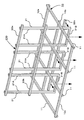
図6は、その作成した枠体を、前述の水平配筋枠10に取り付ける工程を示す斜視図である。
次に、図に示すように、垂直縦筋材11の垂直縦筋材架設部21B側先端が、水平配筋枠10の格子目内に遊嵌されるように、上記枠体200を水平配筋枠10に挿入して取り付ける。このとき、垂直横筋材22a,22bを取り付けた面が正面側となるようにする。
FIG. 6 is a perspective view showing a process of attaching the created frame to the horizontal reinforcing
Next, as shown in the figure, the
そして、上記枠体200を遊嵌したまま、先端が略直線上に揃えられた垂直縦筋材架設部21Bの背面側全体に対し、垂直横筋材22cを溶接等により固定する。
以上で、基礎用配筋枠が完成する。
Then, with the
The foundation reinforcement frame is thus completed.
前述のように、基礎用配筋枠及びコンクリート基礎の荷重がかかる垂直横筋材22c及び垂直縦筋材架設部21Bの箇所を、点で溶接等して固定するのではなく、面全体で強固に固定するので、耐強度の面において著しい効果を発揮する。
また、垂直横筋材22cと垂直縦筋材架設部21Bとを面全体で固定するので、これら両部材を固定するときの位置合わせが、点で固定するときに比べて容易である。
As described above, the portions of the vertical horizontal reinforcing
In addition, since the vertical
なお、垂直横筋材22a,22b,22cは、水平配筋枠10の両端に配される水平縦筋材11間の内側の幅よりも長尺に形成されているので、垂直配筋枠20が水平配筋枠10から脱落することなく、垂直配筋枠20の位置を調整することが可能となっている。
In addition, since the vertical horizontal reinforcing
<折畳方法>
前述のように製造された基礎用配筋枠を建設現場へ搬送する際、起立した垂直配筋枠20を垂直横筋材22c中心に回動させて略平面状に折り畳むことにより、基礎用配筋枠の全体をコンパクトにし、搬送を容易にすることが可能となる。
以下、この基礎用配筋枠の折畳方法について、図を用いて具体的に説明する。
<Folding method>
When transporting the reinforcing bar frame for foundations manufactured as described above to the construction site, the vertical reinforcing
Hereinafter, the folding method of the foundation reinforcement frame will be specifically described with reference to the drawings.
図7は、本発明の実施の形態において、折り畳む際の基礎用配筋枠を示す斜視図である。
図に示すように、折り畳む際には、まず、垂直配筋枠20を正面側(水平横筋12c側)に移動させる。
そして、垂直横筋材22aを水平横筋材12aに接近させるように、垂直横筋材22cを回動軸として垂直配筋枠20を図の矢印方向に回動させ、水平配筋枠10と垂直配筋枠20とが互いに略同一平面となるように折り畳む。
図8は、その折り畳んだ状態を示す斜視図である。
図に示すように、基礎用配筋枠を折り畳むと、水平配筋枠10及び垂直配筋枠20が略同一平面を形成してコンパクトになり、容易に搬送可能となるとともに、収納スペースの削減が可能となる。
FIG. 7 is a perspective view showing a reinforcing bar frame for foundation when folded in the embodiment of the present invention.
As shown in the figure, when folding, first, the
Then, the vertical reinforcing
FIG. 8 is a perspective view showing the folded state.
As shown in the figure, when the foundation bar arrangement frame is folded, the horizontal
次に、この基礎用配筋枠を側面から見た図を用いて、その折り畳むまでの過程について詳細に説明する。 Next, the process up to the folding will be described in detail with reference to a side view of the reinforcing bar frame for foundation.
図9は、本発明の実施の形態における垂直配筋枠20が起立した状態の基礎用配筋枠の側面図である。
図に示すように、垂直配筋枠20起立時には、この垂直配筋枠20が、水平配筋枠10及び設置面に対し略垂直となっている。
FIG. 9 is a side view of the foundation bar arrangement frame in a state where the vertical
As shown in the figure, when the
図10は、本実施の形態における基礎用配筋枠を折り畳む際の途中を状態示す側面図である。点線部分は、上記起立した状態の垂直配筋枠20を示している。
図に示すように、その起立状態の垂直配筋枠20を、正面側(水平横筋材12c側)に移動させながら、垂直横筋材22cを回動軸として図の曲線矢印方向に回動させると、垂直配筋枠20の垂直横筋材22aが水平配筋枠10の水平横筋材12aに接近するように、基礎用配筋枠が折り畳まれる。
FIG. 10 is a side view showing a state in the middle of folding the reinforcing bar frame for foundation in the present embodiment. A dotted line portion indicates the vertical reinforcing
As shown in the figure, when the vertical reinforcing
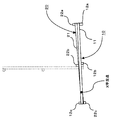
図11は、本実施の形態における基礎用配筋枠を完全に折り畳んだ状態を示す側面図である。点線部分は、上記起立した状態の垂直配筋枠20を示している。
図に示すように、垂直配筋枠20の垂直縦筋材架設部21Bが水平配筋枠10の水平横筋材12cに当接するまで引き寄せ、垂直縦筋材起立部21Aが水平横筋材12bに当接するまで、上記回動させると、基礎用配筋枠を折り畳むことができる。
FIG. 11 is a side view showing a state in which the foundation reinforcing frame in the present embodiment is completely folded. A dotted line portion indicates the vertical reinforcing
As shown in the figure, the vertical reinforcing
また、このとき、水平配筋枠10と垂直配筋枠20とが側面視X字状に交差するように折り畳まれて重なり、略同一平面を形成する。
このように側面視X字状に折り畳んだときには、図に示すように、水平横筋材12a,12b,12cは、側方から見て、順に水平縦枠11の下方、下方、X字交点を挟んで上方に配される。
一方、垂直横筋材22a,22b,22cは、側方から見て、順に垂直縦枠21の上方、上方、X字交点を挟んで下方に配される。
すなわち、水平配筋枠10と垂直配筋枠20とにより挟まれる面側に、各横筋材12a,12b,12c,22a,22b,22cのいずれもが位置しないように構成されている。
従って、折り畳んだときに、各横筋材12a,12b,12c,22a,22b,22cが各縦筋材11,21に当接することなく、スムーズに薄く折り畳むことが可能となっている。
At this time, the horizontal reinforcing
In this way, when folded in an X shape when viewed from the side, as shown in the figure, the horizontal
On the other hand, the
That is, it is configured such that none of the
Therefore, when folded, the
<本実施の形態における効果>
以上説明したように、本実施の形態における基礎用配筋枠によれば、垂直縦筋材架設部21Bの一方の面全体を垂直横筋材22cに接合するので、最も負荷のかかる垂直配筋枠20の底部側を強固に固定することができ、耐強度の面において著しい効果を奏する。
また、点ではなく、面全体で接合するので、溶着等を行う際の位置合わせが容易となる。
また、垂直配筋枠20を起立させるとき、垂直横筋材22cと垂直縦筋材架設部21Bとが両方地面に接するように構成されているので、その接地面積を大きくとることができ、垂直配筋枠20を完全に固定する前の位置決めの際に、垂直配筋枠20が不意に倒れることなく、安定して起立させることができる。
<Effect in the present embodiment>
As described above, according to the reinforcing bar frame for foundation in the present embodiment, since one whole surface of the vertical vertical reinforcing
Moreover, since it joins not the point but the whole surface, the alignment at the time of performing welding etc. becomes easy.
Further, when the vertical reinforcing
また、本実施の形態における基礎用配筋枠によれば、起立した垂直配筋枠20を垂直横筋材22c中心に回動させて水平配筋枠10と垂直配筋枠20とを側面視X字状に折り畳み、最終的に略平面状に折り畳むことにより、基礎用配筋枠の全体を薄くコンパクトにし、容易に搬送することが可能となる。また、保管の際にもそのスペースの削減が可能となる。
Further, according to the reinforcing bar frame for foundation in the present embodiment, the vertical reinforcing
また、本実施の形態における基礎用配筋枠によれば、上記のように折り畳むとき、各横筋材12a,12b,12c,22a,22b,22cのいずれもが、水平配筋枠10と垂直配筋枠20とにより挟まれる面側に位置しないように構成されているので、折り畳んだときに、各横筋材12a,12b,12c,22a,22b,22cが各縦筋材11,21に当接せず、スムーズに薄く折り畳むことが可能となる。
Further, according to the reinforcing bar frame for foundation in the present embodiment, when folded as described above, each of the
また、本実施の形態における基礎用配筋枠によれば、垂直配筋枠20は、直接水平配筋枠10と固定されることなく、水平横筋材12b,12c及び水平縦筋材11により区切られる格子目内に遊嵌されているので、この格子目内において、コンクリート基礎の壁部分を補強する垂直配筋枠20の水平縦横方向及び垂直高さ方向の位置を簡単に調整することが可能となっている。
Further, according to the basic reinforcing bar frame in the present embodiment, the vertical reinforcing
<本実施の形態の他の例>
なお、上記の実施例は本発明の好適な実施の一例であり、本発明の実施例は、これに限定されるものではなく、本発明の要旨を逸脱しない範囲において種々変形して実施することが可能となる。
<Another example of the present embodiment>
The above-described embodiment is an example of a preferred embodiment of the present invention. The embodiment of the present invention is not limited to this embodiment, and various modifications may be made without departing from the scope of the present invention. Is possible.
例えば、基礎用配筋枠は、図に示された形状に限定されるものではなく、基礎用配筋枠を構成する各縦筋材及び横筋材の本数及びその相対的位置、ならびに各寸法については、構築するコンクリート基礎の寸法に応じて適宜変更可能である。
また、本実施の形態における基礎用配筋枠を並べて配置して、各基礎用配筋枠同士を固定具等により互いに固定することで、比較的大きな寸法のコンクリート基礎にも対応可能である。
また、比較的大きな寸法のコンクリート基礎を補強するときには、長尺の水平横筋材12a,12b,12c及び垂直横筋材22a,22b,22cを用い、水平縦筋材11及び垂直縦筋材12の本数を増加させる等して対応するようにしてもよい。
また、本実施の形態では、水平配筋枠10において互いに隣接する格子目に連続して垂直縦筋材21を遊嵌するものであるが、格子目数個おきに遊嵌するようにしてもよい。
For example, the reinforcing bar frame for the foundation is not limited to the shape shown in the figure, and the number and relative position of each of the vertical and horizontal reinforcing bars constituting the reinforcing bar frame for the foundation, and the respective dimensions. Can be appropriately changed according to the dimensions of the concrete foundation to be constructed.
Further, by arranging the bar arrangement frames for the foundation in this embodiment side by side and fixing the bar arrangement frames for the foundation to each other with a fixture or the like, it is possible to deal with a concrete foundation having a relatively large size.
When reinforcing a concrete foundation having a relatively large size, the horizontal
In the present embodiment, the vertical
また、基礎用配筋枠を枠組みして構成する建材は、通常用いられる鉄筋であってもよいし、一定の強度を備えたものであれば、その材料は限定されない。 In addition, the building material configured by framing the reinforcing bar frame for foundation may be a commonly used reinforcing bar, and the material is not limited as long as it has a certain strength.
10 水平配筋枠
11 水平縦筋材
12a,12b,12c 水平横筋材
20 垂直配筋枠
21 垂直縦筋材
21A 垂直縦筋材起立部
21B 垂直縦筋材架設部
22a,22b,22c 垂直横筋材
200 枠体
DESCRIPTION OF
Claims (5)
前記水平配筋枠(10)は、前記設置面に対し略水平かつ互いに略平行に所定間隔で配される棒材である水平縦筋材(11)と、該水平縦筋材に対し略直交に架設される棒材である水平横筋材(11a,11b,11c)とを有して構成され、
前記垂直配筋枠(20)は、前記水平配筋枠(10)に対し起立する全体U字形状の垂直縦筋材(21)と、該垂直縦筋材(21)に対し略直交に架設される棒材である垂直横筋材(22a,22b,22c)とを有して構成され、
前記前記垂直縦筋材(21)は、前記水平縦筋材(11)及び前記水平横筋材(11a,11b,11c)により区切られて形成される格子目内に遊嵌されることを特徴とする基礎用配筋枠。 A horizontal reinforcing frame (10) in a plane substantially rectangular lattice arranged horizontally with respect to the installation surface, and a vertical reinforcing frame in a plane (substantially rectangular lattice) assembled in a standing manner with respect to the horizontal reinforcing frame (10). (20) and a reinforcement frame for a foundation that reinforces the foundation of a building,
The horizontal reinforcing bar frame (10) is a horizontal vertical reinforcing bar (11) which is a bar arranged substantially horizontally and substantially parallel to the installation surface at a predetermined interval, and is substantially orthogonal to the horizontal vertical reinforcing bar. And horizontal transverse bars (11a, 11b, 11c) which are rods installed on
The vertical reinforcing bar frame (20) is installed in a generally U-shaped vertical vertical reinforcing bar (21) standing up with respect to the horizontal reinforcing bar frame (10) and substantially perpendicular to the vertical vertical reinforcing bar (21). A vertical transverse bar (22a, 22b, 22c) that is a bar to be made,
The vertical vertical bars (21) are loosely fitted in a lattice formed by being divided by the horizontal vertical bars (11) and the horizontal horizontal bars (11a, 11b, 11c). The reinforcing bar frame for the foundation.
前記垂直縦筋材架設部(21B)は、略全面にわたって前記垂直横筋材(22c)に対し固着されることを特徴とする請求項1記載の基礎用配筋枠。 The vertical vertical bar (21) includes at least a pair of vertical vertical bar upright portions (21A) that are substantially parallel to each other, and the at least one pair of vertical vertical bars (21A). A vertical longitudinal bar construction part (21B) that is a bar material temporarily installed between the muscle standing parts (21A),
The reinforcing bar frame for a foundation according to claim 1, wherein the vertical longitudinal bar construction part (21B) is fixed to the vertical horizontal bar (22c) over substantially the entire surface.
前記水平横筋材(11a,11b,11c)及び前記垂直横筋材(22a,22b,22c)が、前記水平縦筋材(11)及び前記垂直縦筋材(21)の外側となるように、前記水平配筋枠(10)及び前記垂直配筋枠(20)が略平面を形成して重畳可能に構成されていることを特徴とする請求項3記載の基礎用配筋枠。 When the vertical reinforcement frame (20) is rotated,
The horizontal horizontal bars (11a, 11b, 11c) and the vertical horizontal bars (22a, 22b, 22c) are positioned outside the horizontal vertical bars (11) and the vertical vertical bars (21). The horizontal reinforcing frame (10) and the vertical reinforcing frame (20) are configured so as to be superposed by forming a substantially flat surface.
前記水平縦筋材(11)及び前記垂直縦筋材(21)が、側面視X字状を形成するように、前記水平配筋枠(10)及び前記垂直配筋枠(20)が略平面を形成して重畳可能に構成されていることを特徴とする請求項4記載の基礎用配筋枠。 When the vertical reinforcement frame (20) is rotated,
The horizontal reinforcing bar frame (10) and the vertical reinforcing bar frame (20) are substantially flat so that the horizontal vertical bar member (11) and the vertical vertical bar member (21) form an X shape in a side view. The reinforcing bar frame for foundation according to claim 4, wherein the frame is configured to be superposed.
Priority Applications (1)
| Application Number | Priority Date | Filing Date | Title |
|---|---|---|---|
| JP2008104760A JP2009256902A (en) | 2008-04-14 | 2008-04-14 | Bar arrangement frame for foundation |
Applications Claiming Priority (1)
| Application Number | Priority Date | Filing Date | Title |
|---|---|---|---|
| JP2008104760A JP2009256902A (en) | 2008-04-14 | 2008-04-14 | Bar arrangement frame for foundation |
Publications (1)
| Publication Number | Publication Date |
|---|---|
| JP2009256902A true JP2009256902A (en) | 2009-11-05 |
Family
ID=41384655
Family Applications (1)
| Application Number | Title | Priority Date | Filing Date |
|---|---|---|---|
| JP2008104760A Pending JP2009256902A (en) | 2008-04-14 | 2008-04-14 | Bar arrangement frame for foundation |
Country Status (1)
| Country | Link |
|---|---|
| JP (1) | JP2009256902A (en) |
Cited By (1)
| Publication number | Priority date | Publication date | Assignee | Title |
|---|---|---|---|---|
| PL447964A1 (en) * | 2024-03-08 | 2025-09-15 | Compact-Project.Pl Spółka Z Ograniczoną Odpowiedzialnością | Self-climbing tower structure with a ballast foundation and method for constructing a self-climbing tower structure |
-
2008
- 2008-04-14 JP JP2008104760A patent/JP2009256902A/en active Pending
Cited By (1)
| Publication number | Priority date | Publication date | Assignee | Title |
|---|---|---|---|---|
| PL447964A1 (en) * | 2024-03-08 | 2025-09-15 | Compact-Project.Pl Spółka Z Ograniczoną Odpowiedzialnością | Self-climbing tower structure with a ballast foundation and method for constructing a self-climbing tower structure |
Similar Documents
| Publication | Publication Date | Title |
|---|---|---|
| MXPA04009388A (en) | Tilt-up concrete wall panel form and method of fabricating same. | |
| KR102440826B1 (en) | Column form system using deckplate form and construction method for the same | |
| KR102357050B1 (en) | Column form system using deckplate form | |
| JP4815360B2 (en) | Foundation rebar connector | |
| JP2014136956A (en) | Roof structure and construction method of the same | |
| CN104164927A (en) | Steel bar structure of reinforced concrete wall plate and construction method thereof | |
| JP2009256902A (en) | Bar arrangement frame for foundation | |
| JP6832568B2 (en) | Reinforcement structure of stirrup bar unit and reinforced concrete beam | |
| JP5697942B2 (en) | Reinforcing bar unit and foundation reinforcing bar unit and foundation reinforcing bar structure | |
| JP3138112U (en) | Roof unit structure and connecting hardware used therefor | |
| JP2020133238A (en) | Reinforcing bar structure, deck plate installation method and reinforced concrete structure construction method | |
| JP2810937B2 (en) | Cloth reinforcement frame reinforcement method of cloth foundation reinforcement | |
| JP2005194878A (en) | Reinforcing bar connecting structure and method for producing reinforced unit | |
| JPH0714432Y2 (en) | Foundation frame | |
| JPH09209500A (en) | Prefabricated reinforcement member for rc structure | |
| KR20220036491A (en) | Steel Form Beam And Construction Method Using Thereof | |
| JP4392684B2 (en) | Rebar rod jig, rebar rod assembly method | |
| JP4724791B2 (en) | Support structure for wooden buildings, wooden buildings and metal bundles | |
| JP3026166B2 (en) | Reinforcement members and method of construction | |
| JP4933847B2 (en) | Manufacturing method for solid foundation corner corner unit rebar | |
| JP4448752B2 (en) | Outer wall member supporting hardware and outer wall member standing method | |
| JP2000145017A (en) | Dowel bar, and semi precast concrete slab using it | |
| JP2002256567A (en) | Foundation reinforcement and foundation reinforcement structure using this foundation reinforcement | |
| JP5458454B2 (en) | Foundation beam structure of reinforced concrete structure and its construction method | |
| JP4633506B2 (en) | Rebar rod manufacturing method and reinforcing bar rod manufacturing apparatus |