JP2009261237A - Manufacturing method and cooling apparatus for rotor core of motor - Google Patents
Manufacturing method and cooling apparatus for rotor core of motor Download PDFInfo
- Publication number
- JP2009261237A JP2009261237A JP2009097594A JP2009097594A JP2009261237A JP 2009261237 A JP2009261237 A JP 2009261237A JP 2009097594 A JP2009097594 A JP 2009097594A JP 2009097594 A JP2009097594 A JP 2009097594A JP 2009261237 A JP2009261237 A JP 2009261237A
- Authority
- JP
- Japan
- Prior art keywords
- coffin
- hub
- vent plate
- rotor
- portions
- Prior art date
- Legal status (The legal status is an assumption and is not a legal conclusion. Google has not performed a legal analysis and makes no representation as to the accuracy of the status listed.)
- Withdrawn
Links
Images

Classifications
-
- H—ELECTRICITY
- H02—GENERATION; CONVERSION OR DISTRIBUTION OF ELECTRIC POWER
- H02K—DYNAMO-ELECTRIC MACHINES
- H02K1/00—Details of the magnetic circuit
- H02K1/06—Details of the magnetic circuit characterised by the shape, form or construction
- H02K1/22—Rotating parts of the magnetic circuit
- H02K1/32—Rotating parts of the magnetic circuit with channels or ducts for flow of cooling medium
-
- Y—GENERAL TAGGING OF NEW TECHNOLOGICAL DEVELOPMENTS; GENERAL TAGGING OF CROSS-SECTIONAL TECHNOLOGIES SPANNING OVER SEVERAL SECTIONS OF THE IPC; TECHNICAL SUBJECTS COVERED BY FORMER USPC CROSS-REFERENCE ART COLLECTIONS [XRACs] AND DIGESTS
- Y10—TECHNICAL SUBJECTS COVERED BY FORMER USPC
- Y10T—TECHNICAL SUBJECTS COVERED BY FORMER US CLASSIFICATION
- Y10T29/00—Metal working
- Y10T29/49—Method of mechanical manufacture
- Y10T29/49002—Electrical device making
- Y10T29/49009—Dynamoelectric machine
- Y10T29/49012—Rotor
Landscapes
- Engineering & Computer Science (AREA)
- Power Engineering (AREA)
- Motor Or Generator Cooling System (AREA)
- Manufacture Of Motors, Generators (AREA)
- Iron Core Of Rotating Electric Machines (AREA)
- Induction Machinery (AREA)
Abstract
【課題】モータコアのロータ用の通気孔プレートを提供する。
【解決手段】本通気孔プレートは、ハブと、該ハブから延びる複数のスポークと、それを貫通して延びるコフィンボアを各々が有しかつその少なくとも1つがスポークと連結された複数のコフィン部分とを含む。コフィン部分は各々、ハブから半径方向に間隔をおいて配置しかつ該ハブの周りに円周方向に間隔をおいて配置することができ、また各コフィン部分は、外側半径方向端部と、該コフィン部分の周辺部の周りに延びる連結リングとを含む。連結リングは、各外側半径方向端部に係合することができる。本発明の別の実施形態では、電気モータ用のロータを製造する方法もまた提示している。
【選択図】 図2A vent plate for a rotor of a motor core is provided.
The vent plate includes a hub, a plurality of spokes extending from the hub, and a plurality of coffin portions each having a coffin bore extending therethrough and at least one of which is connected to the spoke. Including. Each of the coffin portions can be spaced radially from the hub and circumferentially spaced about the hub, and each coffin portion can include an outer radial end, and A coupling ring extending around the periphery of the coffin portion. A coupling ring can engage each outer radial end. In another embodiment of the present invention, a method for manufacturing a rotor for an electric motor is also presented.
[Selection] Figure 2
Description
本明細書に記載する主題は、総括的にはモータに関し、より具体的には、ロータモータコアを製造する方法及びそれを冷却するための装置に関する。 The subject matter described herein relates generally to motors, and more specifically to a method of manufacturing a rotor motor core and an apparatus for cooling the same.
現在、モータを冷却する公知の方法は、スペーサを用いてロータコアを通気することを含む。一般的に、コアは、積層を含むことができ、またスペーサ(コフィンとしてもまた公知である)は、各積層間に取付けることができる。スペーサは、I形梁、ブロック又はパケットとして構成し、I形梁及びブロックは、単純に間隙をおいて積層を配置させかつ積層間での冷却空気の流れを可能にするように機能することができる。スペーサパケットは中心ボアを含み、中心ボアは、間に配置された各積層のアパーチャと連通し、従って積層を通して横方向に冷却空気を流すことができる。 Currently, known methods for cooling motors include venting the rotor core with spacers. In general, the core can include stacks and spacers (also known as coffins) can be attached between each stack. The spacers are configured as I-beams, blocks or packets, and the I-beams and blocks can function to simply place the stacks with a gap and to allow cooling air flow between the stacks. it can. The spacer packet includes a central bore that communicates with the apertures of each stack disposed therebetween, thus allowing cooling air to flow laterally through the stack.
スペーサパケットは一般的に、組立、スタンプ加工、溶接及び機械加工のような多くの二次加工工程によって固定される。 Spacer packets are typically secured by a number of secondary processing steps such as assembly, stamping, welding and machining.
上記の方法の1つの欠点は、各々が積層間にスペーサを固定することを必要とし、それによって製造費用が大幅に増加することである。 One drawback of the above method is that each requires fixing spacers between the stacks, thereby greatly increasing manufacturing costs.
従って今日まで、モータを製造する適当な方法又はモータを冷却するための適当な装置は入手できていない。 Thus, to date, no suitable method for manufacturing a motor or a suitable device for cooling the motor is available.
本発明の1つの実施形態では、電気モータ用のロータを製造する方法を提供し、本方法は、少なくとも1つのブランクを準備するステップと、該少なくとも1つのブランクを切断して少なくとも1つの通気孔プレートを形成するステップとを含む。通気孔プレートは、ハブと、該ハブから延びる複数のスポークと、それを貫通して延びるコフィンボアを各々が有しかつその少なくとも1つがスポークと連結された複数のコフィン部分とを含む。コフィン部分は各々、ハブから半径方向に間隔をおいて配置しかつ該ハブの周りに円周方向に間隔をおいて配置することができ、また各コフィン部分は、外側半径方向端部と、該コフィン部分の周辺部の周りに延びる連結リングとを含む。連結リングは、各外側半径方向端部に係合することができる。本方法はさらに、複数のロータ積層を準備するステップと、
複数積層間に少なくとも1つの通気孔プレートを交互配置してロータ組立体スタックを形成するステップと、ロータ組立体スタック内に金属結合剤物質を注入して通気孔プレート及び積層を共にかつ少なくとも1つの通気孔プレートの各コフィン部分を共に結合するステップと、ロータ組立体スタックの外径の一部分を除去し、それによって各コフィン部分の外側半径方向端部を除去して各コフィンボアが外気と連通するようにするステップとを含むことができる。
In one embodiment of the present invention, a method of manufacturing a rotor for an electric motor is provided, the method comprising providing at least one blank and cutting the at least one blank to at least one vent. Forming a plate. The vent plate includes a hub, a plurality of spokes extending from the hub, and a plurality of coffin portions each having a coffin bore extending therethrough and at least one of which is coupled to the spoke. Each of the coffin portions can be spaced radially from the hub and circumferentially spaced about the hub, and each coffin portion can include an outer radial end, and A coupling ring extending around the periphery of the coffin portion. A coupling ring can engage each outer radial end. The method further comprises providing a plurality of rotor stacks;
Interleaving at least one vent plate between a plurality of stacks to form a rotor assembly stack, and injecting a metal binder material into the rotor assembly stack to combine the vent plates and the stack together and at least one Coupling each coffin portion of the vent plate together and removing a portion of the outer diameter of the rotor assembly stack, thereby removing the outer radial end of each coffin portion so that each coffin bore communicates with the outside air And the step of.
本発明の別の実施形態では、モータコアのロータ用の通気孔プレートを提供し、本通気孔プレートは、ハブと、該ハブから延びる複数のスポークと、それを貫通して延びるコフィンボアを各々が有する複数のコフィン部分とを含む。コフィン部分の少なくとも1つは、スポークと連結される。コフィン部分は各々、ハブから半径方向に間隔をおいて配置しかつ該ハブの周りに円周方向に間隔をおいて配置することができる。各コフィン部分は、外側半径方向端部と、該コフィン部分の周辺部の周りに延びる連結リングとを含み、連結リングは、各外側半径方向端部に係合する。 In another embodiment of the present invention, a vent plate for a rotor of a motor core is provided, the vent plate having a hub, a plurality of spokes extending from the hub, and a coffin bore extending therethrough. A plurality of coffin portions. At least one of the coffin portions is connected to the spoke. Each of the coffin portions can be spaced radially from the hub and circumferentially spaced about the hub. Each coffin portion includes an outer radial end and a connecting ring extending around the periphery of the coffin portion, the connecting ring engaging each outer radial end.
本開示のその他の特徴及び利点は、添付の図面に関連してなした以下の説明を参照することによって明らかになるであろう。 Other features and advantages of the present disclosure will become apparent with reference to the following description taken in conjunction with the accompanying drawings.
次に添付の図面について簡単に説明する。 The accompanying drawings will now be described briefly.
同じ参照符号は、幾つかの図を通して同一の又は対応する構成要素及びユニットを示しており、これら幾つかの図は、特にそうでないことを指摘しない限り、正確な縮尺になっていない。 The same reference numbers indicate the same or corresponding components and units throughout the several views, and these several views are not drawn to scale unless specifically noted otherwise.
本発明の1つの実施形態は、通気孔プレートの使用を含む、電気モータ用のロータを製造する方法を含む。本発明によって得られる1つの具体的な利点は、ロータ積層を通して冷却目的の空気流を供給することができると同時に、溶接又はその他の方法によってロータ積層に対して次に固定しなければならない別個のスペーサブロックを組立てる、スタンプ加工する又は機械加工するような多くの二次工程の必要性を排除することができることである。 One embodiment of the present invention includes a method of manufacturing a rotor for an electric motor that includes the use of vent plates. One particular advantage obtained by the present invention is that a separate air flow that can be supplied to the rotor stack by welding or other methods while being able to supply an air flow for cooling through the rotor stack. It is possible to eliminate the need for many secondary processes such as assembling, stamping or machining the spacer block.
添付の図面を参照して以下に説明する特許請求発明の具体的な構成及び配置は、例示目的のためのみのものである。当業者の予測範囲内にあるその他の構成及び配置は、提出した特許請求の範囲の技術思想及び技術的範囲から逸脱することなく製造し、使用し又は販売することができる。例えば、本明細書では、本発明の幾つかの実施形態は電気モータ用のロータコアに関して説明しているが、本発明の実施形態は、モータを冷却することが有利であるあらゆる装置設定において実施することができることは、当業者には分かるであろう。 The specific configurations and arrangements of the claimed invention described below with reference to the accompanying drawings are for illustrative purposes only. Other configurations and arrangements within the purview of those skilled in the art may be manufactured, used, or sold without departing from the spirit and scope of the appended claims. For example, although some embodiments of the present invention are described herein with reference to a rotor core for an electric motor, embodiments of the present invention are implemented in any device setting where it is advantageous to cool the motor. One skilled in the art will recognize that this is possible.
本明細書で用いる場合に、数詞のない形で記載した要素又は機能は、そうでないことを明確に述べていない限り、複数のそのような要素又は機能を排除するものではないことを理解されたい。さらに特許請求発明の「1つの実施形態」の説明は、記載した特徴をさらに組み込んだ付加的な実施形態の存在を排除すると解釈すべきでない。 It should be understood that, as used herein, an element or function described in an unnumeral form does not exclude a plurality of such elements or functions unless explicitly stated otherwise. . Furthermore, the description of “one embodiment” of the claimed invention should not be interpreted as excluding the existence of additional embodiments that also incorporate the recited features.
本発明の様々な実施形態の特定の特徴は、幾つかの図面においては示しているがその他の図面では示していない場合があるが、それは単に便宜上のためだけである。本発明の原理によると、1つの図面の1つ又は複数の特徴は、他の図面のいずれかにおける特徴の幾つか又は全てと組合せることができる。本明細書で用いる場合の「備える」「含む」「有する」及び「持つ」という用語は、広くかつ包括的に解釈されるべきであり、如何なる物理的相互結合にも制限されるものではない。さらに、本明細書に開示したあらゆる実施形態は、唯一の実施可能な実施形態と解釈すべきでない。むしろ多くの修正及びその他の実施形態が、特許請求の範囲の技術的範囲内に含まれることを意図している。 Although specific features of various embodiments of the invention may be shown in some drawings and not in others, this is for convenience only. In accordance with the principles of the invention, one or more features of one drawing may be combined with some or all of the features in any of the other drawings. The terms “comprising”, “including”, “having” and “having” as used herein are to be interpreted broadly and comprehensively and are not limited to any physical interconnection. Moreover, any embodiments disclosed herein are not to be construed as the only possible embodiments. Rather, many modifications and other embodiments are intended to be included within the scope of the claims.
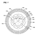
次に図1を参照すると、本発明の態様は、その全体を符号100で示すロータ積層を含むことができる。ロータ積層100は、ロータコアを形成するように通気孔プレートと共に積層された複数のロータ積層の1つとすることができる。各ロータ積層100は、一般的に銅又はアルミニウムのような熱伝導性材料(図示せず)を含む複数のアパーチャ140を含むことができる。この図示した具体的な実施例に示すように、各配線アパーチャは、タブ160及び成形端部部分180を含み、これらは、モータの様々な電磁特性を達成する様々なジオメトリとして構成可能であることはよく知られている。さらに、各ロータ積層100はさらに、中心アパーチャ190を含み、この中心アパーチャ190は、例えばモータシャフト(図示せず)に取付けるように構成されたキー溝192を備えることができる。第1の複数の冷却アパーチャ120が、冷却目的のために設けられ、円周方向に間隔をおいて配置されかつアパーチャ190から半径方向に間隔をおいて配置される。ファン(図示せず)を使用して、回転軸線(x)に対してほぼ軸方向にアパーチャ120を通って流れる冷却流体の層流を発生させるようにすることができる。
Referring now to FIG. 1, aspects of the present invention can include a rotor stack, generally indicated at 100. The
また、ロータ積層100の各々は、ほぼディスク様の外側構成を各々が備えることができ、従って各々が、その外径(d)に対して比較的小さな幅(w)を有することが分かるであろう。さらに、ロータ積層100の各々は、強磁性材料を含むことができ、この強磁性材料は、レーザビーム又は高圧水切断のような様々な切断媒体を用いてスタンプ加工及び/又は切断することができる。
It can also be seen that each of the
次に図2を参照すると、本発明の1つの実施形態による通気孔プレートは、その全体を符号200で示している。ブランク202には、炭素鋼、亜鉛メッキ鋼、ステンレス鋼、アルミニウム及び同様のもののような金属薄板を含むことができる。通気孔プレート200は、従来型の機械加工、レーザ、又は水ジェット切断法を用いてブランクから切断することができ、このことは、図3を参照してより詳細に説明する。
Referring now to FIG. 2, a vent plate according to one embodiment of the present invention is indicated generally by the
通気孔プレート200は、ハブ204、複数のスポーク206、複数のコフィン208及び連結リング210を含むことができる。図示するように、ハブ204は、その形状がほぼ円形であり、ロータシャフトに取付けるように(図4に示すように)構成された中心設置取付けボア212を有する。ハブはさらに、該ハブの周辺部の周りに設置された複数の付属肢214を含む。付属肢214は、ハブ204に取付けかつ該ハブ204から延びることができる複数のスポーク206に取付けるように構成することができる。
The
ハブの付属肢214及びスポーク206の内側部分は、ハブの外周辺部に取付けることができる。この設計は、図示するように7つのスポークを含むが、スポークの数及び寸法は、エンジン設計に応じて変更することができることを理解されたい。
The hub appendages 214 and the inner portions of the
さらに図2を参照すると、通気孔プレートは、ハブ204から半径方向に間隔をおいて配置されかつ該ハブ204の周りに円周方向に間隔をおいて配置された複数のコフィン(スペーサパケットとしても公知である)208を含むことができる。コフィン208は、ハブ204の周りに不連続リングを形成することができ、かつスペーサ部分を所定の位置に保持するように構成することができる少なくとも何らかの2つのスポーク206の内側端部に取付けることができる。コフィン208の外側半径方向端部はさらに、コフィン部分の周辺部の周りに延びる連結リング210に取付けることができ、連結リングは、コフィンの各外側半径方向端部を係合する。連結リングは、スポークに取付けられないコフィンを安定させることができる。
Still referring to FIG. 2, the vent plate is radially spaced from the
ハブ204の外周辺部は、連結リングの内側部分及び2つのスポークの側面部分と組合せて、該ハブの周辺部の周りに通気孔アパーチャ216を形成することができる。通気孔アパーチャ216は、図1の冷却アパーチャ120と整列して、軸方向ボアに対して軸方向の空気流を可能にするように構成することができる冷却通気孔を形成することができる。
The outer periphery of the
図2に示すように、コフィン部分220は、連結リング210に係合した外側半径方向端部を有する複数のコフィン成形スペーサパケットと、スポーク206に取付けることができる内側部分とを含む。各コフィンは、互いに平行に構成すると同時に間隔をおいて配置して、それらの間に冷却アパーチャ216を形成することができる。さらに、それを貫通して延びるコフィンボア218を設けることができる。アパーチャ216は、冷却流体が該アパーチャ216を通って軸方向及び半径方向に流れるのを可能にするように構成することができるが、コフィンボア218は、鋳造時に金属結合剤物質を注入するのを可能にするように構成することができまた鋳造時に金属結合剤で充填された状態になるようになることができ、このことは、図3及び図4を関してより詳細に論議する。
As shown in FIG. 2, the
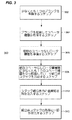
次に図3を参照すると、電気モータ用のロータを製造する方法を、その全体を符号300として提示している。この例示的な方法を説明するのに一層良く役立つように、フローチャートを示す。フローチャートは例示的な段階的方法を示しているが、当業者は、同様の結果を維持しながら各ステップを再配値又は並べ替えることができることが、分かるであろう。 Referring now to FIG. 3, a method for manufacturing a rotor for an electric motor is presented generally as 300. A flowchart is shown to better assist in explaining this exemplary method. Although the flowchart shows an exemplary step-by-step method, those skilled in the art will appreciate that each step can be rearranged or reordered while maintaining similar results.
本発明の1つの実施形態では、本方法は、少なくとも1つのブランクを準備するステップ302を含む。この実施形態では、ブランクは一般的に、炭素鋼、亜鉛メッキ鋼、ステンレス鋼、アルミニウム及び同様のもので作られた金属薄板とすることができる。ブランクの直径は、ロータ組立体及びモータの寸法に応じて変更することができることもさらに理解されたい。例えば、ブランクの厚さは、およそ0.125インチとすることができるが、本発明の実施においては、複数ブランクを共に接合することができることも理解されたい。 In one embodiment of the invention, the method includes providing 302 at least one blank. In this embodiment, the blank can generally be a sheet metal made of carbon steel, galvanized steel, stainless steel, aluminum and the like. It should further be understood that the diameter of the blank can be varied depending on the dimensions of the rotor assembly and motor. For example, the thickness of the blank can be approximately 0.125 inches, but it should also be understood that in the practice of the present invention, multiple blanks can be joined together.
少なくとも1つのブランクを切断して少なくとも1つの通気孔プレートを形成するステップ304は、レーザ切断又は水ジェット切断によって最も良好に達成することができる。従来型の機械加工法もまた用いることができるが、ブランクをレーザ又は水切断する利点には、汚染の可能性が少ないこと、高精度(レーザでは摩耗がないので)であること、及びブランクのゆがみの可能性が減少することが含まれる。水切断が好ましい方法である場合には、ガーネット及び酸化アルミニウムのような研削剤を切断水路として加えることができる。 Step 304 of cutting at least one blank to form at least one vent plate can best be accomplished by laser cutting or water jet cutting. Conventional machining methods can also be used, but the advantages of laser or water cutting the blank are less likely to contaminate, high accuracy (since the laser has no wear), and the blank This includes reducing the possibility of distortion. If water cutting is the preferred method, abrasives such as garnet and aluminum oxide can be added as cutting water channels.
この例示的な実施形態では、少なくとも1つの通気孔プレートを、図2に示す通気孔プレートに機能的に相当させることができ、この少なくとも1つの通気孔プレートは、ハブと、該ハブから延びる複数のスポークと、その各々がそれを貫通して延びるコフィンボアを有しかつその少なくとも1つがスポークと連結され、またその各々がハブから半径方向に間隔をおいて配置されかつ該ハブの周りに円周方向に間隔をおいて配置され、またその各々が外側半径方向端部を含む複数のコフィン部分と、該コフィン部分の周辺部の周りに延びかつ各外側半径方向端部に係合する連結リングとを含む。ここでもまた、通気孔プレートの厚さは、ブランクの基準寸法に応じて決まり、ブランクの基準寸法はさらに、ロータ組立体の寸法に応じて決まる。 In this exemplary embodiment, the at least one vent plate can functionally correspond to the vent plate shown in FIG. 2, wherein the at least one vent plate includes a hub and a plurality extending from the hub. Spokes, each having a coffin bore extending therethrough and at least one of which is coupled to the spokes, each of which is spaced radially from the hub and circumferentially around the hub A plurality of coffin portions spaced apart in the direction and each including an outer radial end; and a coupling ring extending around a periphery of the coffin portion and engaging each outer radial end including. Again, the thickness of the vent plate depends on the blank reference dimension, which in turn depends on the rotor assembly dimension.
複数のロータ積層を準備するステップ306は、図1に示すもののようなロータ積層を準備するステップを含むことができ、このロータ積層は、一般的に銅又はアルミニウムのような熱伝導性材料を含む複数のアパーチャと、タブと、成形端部部分とを含み、これらは、モータの様々な電磁特性を達成する様々なジオメトリとして構成可能であることがよく知られている。さらに、各ロータ積層はさらに、例えばモータシャフトに取付けるように構成されたキー溝を備えた中心アパーチャを含むことができる。第1の複数の冷却アパーチャは、冷却目的のために設けることができ、円周方向に間隔をおいて配置されかつアパーチャから半径方向に間隔をおいて配置される。ファンを使用して、回転軸線(x)に対してほぼ軸方向にアパーチャを通って流れる冷却流体の層流を発生させるようにすることができる。 Preparing 306 a plurality of rotor stacks can include preparing a rotor stack, such as that shown in FIG. 1, which typically includes a thermally conductive material such as copper or aluminum. It is well known that it includes a plurality of apertures, tabs, and molded end portions, which can be configured as various geometries that achieve various electromagnetic characteristics of the motor. In addition, each rotor stack can further include a central aperture with a keyway configured to attach to the motor shaft, for example. The first plurality of cooling apertures may be provided for cooling purposes and are spaced circumferentially and spaced radially from the aperture. A fan can be used to generate a laminar flow of cooling fluid that flows through the aperture substantially axially with respect to the axis of rotation (x).
複数スペーサ積層間に少なくとも1つの通気孔プレートを交互配置してロータ組立体スタックを形成するステップ308は、通気孔プレートとロータ積層とを交互に積み重ねるステップを含むことができ、ここで、ロータ積層は、通気孔プレートのコフィンボアの各々と整列させることができる複数のスロットを含み、またロータ積層の冷却アパーチャは通気孔プレートの通気アパーチャと整列して、例えば外気などの冷却流体がロータ組立体を通って流れるのを可能にするように構成された軸方向及び半径方向冷却ダクトネットワークを形成することができる。1つの例示的な実施形態では、6層のスタックとロータ積層とは、適正な冷却ダクトネットワークを備えたロータ組立体を形成するのに十分であるといえる。
Interleaving at least one vent plate between the plurality of spacer stacks to form a
ロータ組立体スタック内に金属結合剤物質を注入して通気孔プレート及びロータ積層を共に結合しかつ少なくとも1つの通気孔プレートの各コフィン部分を結合するステップ310は、当技術分野では公知のダイカストするステップを含むことができる。この例示的な方法のこのステップでは、例えばアルミニウム又は銅合金などの金属物質を高圧下でロータ組立体スタックの空洞内に強制的に注入することにより、他の部品の中でも特に通気孔プレートのコフィン部分を固定する。別の実施形態では、このステップ310は、回転成形するステップを含むことができ、この回転成形では、ロータ組立体の中心軸線に沿ってゴム鋳型を回転させ、また鋳型の上端中心を通して金属結合剤物質を注入し、金属結合剤が固まるまでゴム鋳型をさらに回転させる。このステップはさらに、冷却アパーチャが金属結合剤によって妨げられないことを保証することができる。図4を参照して後述する最終硬化鋳造物は、完成ロータコアの構成要素として用いることができる。
The
ロータ組立体スタックの外径の一部を除去し、それによって各コフィン部分の外側半径方向端部を除去して各コフィンボアが外気と連通するようにするステップは、最終回転させるステップによって達成することができる。この例示的な実施形態では、回転させるステップは、金属加工旋盤を用いて通気孔プレートの外周部における連結リング部分を除去するステップを含むことができる。本発明の任意選択的な実施形態では、外径円筒研削法を用いることができる。次に、既存のアパーチャは、使用時に完成ロータコアを冷却するように外気と連通することができる半径方向及び軸方向の冷却ダクトネットワークを形成することができる。 The step of removing a portion of the outer diameter of the rotor assembly stack, thereby removing the outer radial end of each coffin portion so that each coffin bore communicates with the outside air is accomplished by a final rotation step. Can do. In this exemplary embodiment, the rotating step can include removing the connecting ring portion at the outer periphery of the vent plate using a metal working lathe. In an optional embodiment of the invention, an outer diameter cylindrical grinding method can be used. The existing apertures can then form a radial and axial cooling duct network that can communicate with the outside air to cool the finished rotor core in use.
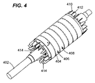
次に図4を参照すると、ダイカストするステップ及び最終回転させるステップ後の完成ロータコアは、その全体を符号400で示しており、ロータシャフト402と、露出した冷却ダクト404と、通気孔プレート406と、積層408と、冷却フィン412及び冷却スロット414を備えた端部キャップ410とを含む。露出冷却ダクト404は、アパーチャ218(図2)と連通し、アパーチャ218は次に、冷却スロット414と連通する。このようにして、ロータコア400を通る冷却通路が形成され、ロータコアの回転時にこの冷却通路を通して冷却空気が導かれる。この例示的なロータコア400は、電気モータで使用するためのものとすることができまた上述した実施形態により製造することができ、これは、スペーサ又はブロック構成要素を組立てる、スタンプ加工する及び溶接することのような多くの二次工程の必要性を取り除く利点がある。
Referring now to FIG. 4, the completed rotor core after the die casting and final rotating steps is indicated generally by the numeral 400, the
本発明の様々な実施形態の特定の特徴は、幾つかの図面においては示しているがその他の図面では示していない場合があるが、それは単に便宜上のためだけである。本発明の原理によると、1つの図面の1つ又は複数の特徴は、他の図面のいずれかにおける特徴の幾つか又は全てと組合せることができる。本明細書で用いる場合の「備える」「含む」「有する」及び「持つ」という用語は、広くかつ包括的に解釈されるべきであり、如何なる物理的相互結合にも制限されるものではない。さらに、本明細書に開示したあらゆる実施形態は、唯一の実施可能な実施形態と解釈すべきでない。むしろ多くの修正及びその他の実施形態が、特許請求の範囲の技術的範囲内に含まれることを意図している。 Although specific features of various embodiments of the invention may be shown in some drawings and not in others, this is for convenience only. In accordance with the principles of the invention, one or more features of one drawing may be combined with some or all of the features in any of the other drawings. The terms “comprising”, “including”, “having” and “having” as used herein are to be interpreted broadly and comprehensively and are not limited to any physical interconnection. Moreover, any embodiments disclosed herein are not to be construed as the only possible embodiments. Rather, many modifications and other embodiments are intended to be included within the scope of the claims.
100 ロータ積層
120 アパーチャ
140 アパーチャ
160 タブ
180 成形端部部分
190 中心アパーチャ
192 キー溝
200 通気孔プレート
202ブランク
204 204
206 スポーク
208 コフィン
210 連結リング
212 中心設置取付けボア
214 付属肢
216 通気孔アパーチャ
218 コフィンボア
220 コフィン部分
400 完成ロータコア
402 ロータシャフト
404 露出冷却ダクト
406 通気孔プレート
408 積層
410 端部キャップ
412 冷却フィン
414 冷却スロット
100
206
Claims (10)
少なくとも1つのブランク(202)を準備するステップと、
前記少なくとも1つのブランク(202)を、少なくとも1つの通気孔プレート(200)を形成するように構成するステップと、を含み、
ここで前記通気孔プレート(200)が、ハブ(204)と、前記ハブ(204)から延びる複数のスポーク(206)と、それを貫通して延びるコフィンボアを各々が有しかつその少なくとも1つが前記スポークと連結された複数のコフィン部分(208)と、前記コフィン部分(208)の周辺部の周りに延びる連結リング(210)と、を含み、前記コフィン部分(208)が各々、前記ハブ(204)から半径方向に間隔をおいて配置されかつ該ハブ(204)の周りに円周方向に間隔をおいて配置され、各前記コフィン部分(208)が、外側半径方向端部を含み、また前記連結リング(210)が各前記外側半径方向端部に係合しており、
本方法がさらに、
複数のロータ積層を準備するステップ(306)と、
前記複数積層(306)間に前記少なくとも1つの通気孔プレート(200)を交互配置してロータ組立体スタックを形成するステップ(308)と、
前記ロータ組立体スタック(308)内に金属結合剤物質を注入して前記通気孔プレート及び積層(306)を共にかつ前記少なくとも1つの通気孔プレート(200)の各コフィン部分(208)を共に結合するステップと、
前記ロータ組立体スタック(308)の外径の一部分を除去し、それによって各前記コフィン部分(208)の外側半径方向端部を除去して各前記コフィンボアが外気と連通するようにするステップと、
を含む方法。 A method for manufacturing a rotor for an electric motor, comprising:
Providing at least one blank (202);
Configuring the at least one blank (202) to form at least one vent plate (200);
Here, the vent plate (200) has a hub (204), a plurality of spokes (206) extending from the hub (204), and a coffin bore extending therethrough, at least one of which is the A plurality of coffin portions (208) connected to the spokes, and a connecting ring (210) extending around a periphery of the coffin portions (208), wherein the coffin portions (208) each include the hub (204). ) Radially spaced from and circumferentially spaced about the hub (204), each said coffin portion (208) including an outer radial end, and A coupling ring (210) engages each said outer radial end;
The method further includes
Preparing a plurality of rotor stacks (306);
Interleaving the at least one vent plate (200) between the plurality of stacks (306) to form a rotor assembly stack (308);
A metal binder material is injected into the rotor assembly stack (308) to bond the vent plate and laminate (306) together and the coffin portions (208) of the at least one vent plate (200) together. And steps to
Removing a portion of the outer diameter of the rotor assembly stack (308), thereby removing the outer radial end of each coffin portion (208) so that each coffin bore is in communication with outside air;
Including methods.
各前記積層(306)が、複数のスロットを含み、
前記複数積層(306)間に前記少なくとも1つの通気孔プレート(200)を交互配置するステップが、前記通気孔プレート(200)のコフィンボアの各々を前記積層(306)のスロットの各々と整列させて軸方向及び半径方向冷却ダクトネットワークを形成するステップを含む、
請求項1乃至3のいずれか1項に記載の方法。 The at least one vent plate (200) comprises a plurality of vent plates;
Each of the stacks (306) includes a plurality of slots,
Interleaving the at least one vent plate (200) between the plurality of stacks (306) aligns each of the coffin bores of the vent plate (200) with each of the slots of the stack (306). Forming axial and radial cooling duct networks;
4. A method according to any one of claims 1 to 3.
ハブ(204)と、
前記ハブ(204)から延びる複数のスポークと、
それを貫通して延びるコフィンボアを各々が有しかつその少なくとも1つが前記スポークと連結された複数のコフィン部分(208)と、を含み、
前記コフィン部分(208)が各々、前記ハブ(204)から半径方向に間隔をおいて配置されかつ該ハブ(204)の周りに円周方向に間隔をおいて配置され、
各前記コフィン部分(208)が、外側半径方向端部を含む、
通気孔プレート。 A vent plate for a motor core rotor,
A hub (204);
A plurality of spokes extending from the hub (204);
A plurality of coffin portions (208) each having a coffin bore extending therethrough and at least one of which is coupled to the spoke;
The coffin portions (208) are each spaced radially from the hub (204) and circumferentially spaced about the hub (204);
Each said coffin portion (208) includes an outer radial end,
Vent plate.
前記連結リング(210)が、各前記外側半径方向端部に係合する、
請求項7記載の装置。 A coupling ring (210) extending around the periphery of the coffin portion (208);
Said connecting ring (210) engages each said outer radial end;
The apparatus of claim 7.
前記スポーク(206)が、その少なくとも2つの位置で各前記コフィン部分(208)の内側部分に連結される、
請求項8記載の装置。 An outer periphery of the hub (204) is connected to the spoke (206) at at least two positions thereof;
The spokes (206) are connected to the inner portion of each of the coffin portions (208) in at least two positions thereof;
The apparatus of claim 8.
Applications Claiming Priority (1)
| Application Number | Priority Date | Filing Date | Title |
|---|---|---|---|
| US12/104,667 US20090261669A1 (en) | 2008-04-17 | 2008-04-17 | Method of making and device for cooling rotor motor cores |
Publications (1)
| Publication Number | Publication Date |
|---|---|
| JP2009261237A true JP2009261237A (en) | 2009-11-05 |
Family
ID=40668108
Family Applications (1)
| Application Number | Title | Priority Date | Filing Date |
|---|---|---|---|
| JP2009097594A Withdrawn JP2009261237A (en) | 2008-04-17 | 2009-04-14 | Manufacturing method and cooling apparatus for rotor core of motor |
Country Status (8)
| Country | Link |
|---|---|
| US (1) | US20090261669A1 (en) |
| EP (1) | EP2110927A3 (en) |
| JP (1) | JP2009261237A (en) |
| CN (1) | CN101562376A (en) |
| BR (1) | BRPI0901386A2 (en) |
| CA (1) | CA2662255A1 (en) |
| MX (1) | MX2009003965A (en) |
| TW (1) | TW200950286A (en) |
Cited By (1)
| Publication number | Priority date | Publication date | Assignee | Title |
|---|---|---|---|---|
| KR101563314B1 (en) | 2013-10-28 | 2015-10-27 | 현대중공업 주식회사 | Open type motor |
Families Citing this family (13)
| Publication number | Priority date | Publication date | Assignee | Title |
|---|---|---|---|---|
| US8362661B2 (en) * | 2010-10-06 | 2013-01-29 | General Electric Company | Ventilated rotor and stator for dynamoelectric machine |
| EP2447145B1 (en) * | 2010-10-29 | 2014-01-01 | Günther Hirn | Electric drive for a bicycle |
| CN102069340B (en) * | 2010-12-10 | 2013-06-12 | 上海电气集团上海电机厂有限公司 | Spot welding positioning tool and spot welding method for double-layer vent slot plate |
| EP2477313B1 (en) * | 2011-01-18 | 2014-04-09 | Bombardier Transportation GmbH | An electric machine |
| CN102904355B (en) * | 2011-07-29 | 2014-10-29 | 西门子公司 | Distance piece assembly of rotor, rotor and motor thereof |
| US20140070658A1 (en) * | 2012-09-10 | 2014-03-13 | Remy Technologies, L.L.C. | Lamination assembly including an inter-lamination thermal transfer member for an electric machine |
| US9013075B2 (en) * | 2012-09-13 | 2015-04-21 | Siemens Industry, Inc. | Induction motors including vent spacers, rotor core assemblies including vent spacers, and methods of operating same |
| US9973049B2 (en) | 2013-03-15 | 2018-05-15 | Techtronic Industries Co. Ltd. | Electric motor |
| US20190309644A1 (en) * | 2018-04-10 | 2019-10-10 | Elysium Solutions LLC | Electrical power generation assembly having recovery gas efficiency |
| JP6944418B2 (en) * | 2018-07-09 | 2021-10-06 | 東芝三菱電機産業システム株式会社 | Rotating machine and rotor |
| CN113014008A (en) * | 2021-02-07 | 2021-06-22 | 珠海格力电器股份有限公司 | Rotor structure, motor, converter and have its centrifuge |
| CN113890234B (en) * | 2021-10-11 | 2023-01-31 | 浙江大学先进电气装备创新中心 | A closed motor cooling device with circulation convection between rotor holes |
| CN119927639B (en) * | 2025-03-20 | 2025-09-02 | 无锡集磁科技有限公司 | A cutting device capable of positioning a magnetic core |
Family Cites Families (6)
| Publication number | Priority date | Publication date | Assignee | Title |
|---|---|---|---|---|
| US508637A (en) * | 1893-11-14 | Armature-core | ||
| US996927A (en) * | 1904-12-08 | 1911-07-04 | Otis Elevator Co | Armature-core. |
| US3684906A (en) * | 1971-03-26 | 1972-08-15 | Gen Electric | Castable rotor having radially venting laminations |
| JPS50142105U (en) * | 1974-05-13 | 1975-11-22 | ||
| US4301386A (en) * | 1977-08-12 | 1981-11-17 | General Electric Co. | Rotor laminae assembly for a cast rotor dynamoelectric machine |
| JPS5532683U (en) * | 1978-08-24 | 1980-03-03 |
-
2008
- 2008-04-17 US US12/104,667 patent/US20090261669A1/en not_active Abandoned
-
2009
- 2009-04-07 EP EP09157537A patent/EP2110927A3/en not_active Withdrawn
- 2009-04-09 CA CA002662255A patent/CA2662255A1/en not_active Abandoned
- 2009-04-09 TW TW098111884A patent/TW200950286A/en unknown
- 2009-04-14 JP JP2009097594A patent/JP2009261237A/en not_active Withdrawn
- 2009-04-14 BR BRPI0901386-5A patent/BRPI0901386A2/en not_active IP Right Cessation
- 2009-04-15 MX MX2009003965A patent/MX2009003965A/en unknown
- 2009-04-17 CN CNA2009101354568A patent/CN101562376A/en active Pending
Cited By (2)
| Publication number | Priority date | Publication date | Assignee | Title |
|---|---|---|---|---|
| KR101563314B1 (en) | 2013-10-28 | 2015-10-27 | 현대중공업 주식회사 | Open type motor |
| US9755467B2 (en) | 2013-10-28 | 2017-09-05 | Hyundai Electric & Energy Systems Co., Ltd. | Open-type induction motor |
Also Published As
| Publication number | Publication date |
|---|---|
| TW200950286A (en) | 2009-12-01 |
| MX2009003965A (en) | 2009-10-23 |
| CA2662255A1 (en) | 2009-10-17 |
| BRPI0901386A2 (en) | 2010-01-26 |
| US20090261669A1 (en) | 2009-10-22 |
| EP2110927A3 (en) | 2011-11-23 |
| CN101562376A (en) | 2009-10-21 |
| EP2110927A2 (en) | 2009-10-21 |
Similar Documents
| Publication | Publication Date | Title |
|---|---|---|
| US20090261669A1 (en) | Method of making and device for cooling rotor motor cores | |
| US11218050B2 (en) | Motor stator back-iron cooling through internal channels | |
| US7692352B2 (en) | Apparatus and method for cooling rotor and stator motor cores | |
| JP2024507005A (en) | Rotor for axial flux motor and manufacturing method | |
| WO2003047069A1 (en) | Axial gap type dynamo-electric machine | |
| US8872399B2 (en) | Stator winding assembly and method | |
| CN115021440B (en) | An oil-cooled motor | |
| CN111033970A (en) | Rotor | |
| JP2019146332A (en) | Rotating electrical machine rotor | |
| JP2012161134A (en) | Rotary electric machine | |
| US7546674B2 (en) | Method of rotor assembly without the hub | |
| CN109120081A (en) | Stator punch, stator core provided with the same, stator and motor | |
| JP2020096474A (en) | Rotor of rotating electric machine | |
| JP2012023805A (en) | Stator of electric motor and manufacturing method of the same | |
| KR101247685B1 (en) | Rotor, motor having the rotor and rotor manufacturing method | |
| CN114365388B (en) | Electric machine with various recesses definedly positioned in a wet-running stator | |
| CN118947050A (en) | Stator of rotating electric machine, rotor of rotating electric machine, and method for manufacturing rotating electric machine | |
| CN110953250B (en) | Magnetic suspension bearing rotor structure, motor and air conditioner | |
| JP2018148746A (en) | Rotor and manufacturing method for rotor | |
| JP2010263714A (en) | Motor core and method for manufacturing the same | |
| JP2004343915A (en) | Electric motor | |
| JP2010213387A (en) | Stator and motor | |
| JP5250908B2 (en) | Manufacturing method of axial gap type motor | |
| JP2003143787A (en) | Rotor structure of electric motor and method of manufacturing the same | |
| JP6360709B2 (en) | Axial gap type rotating electrical machine |
Legal Events
| Date | Code | Title | Description |
|---|---|---|---|
| A300 | Application deemed to be withdrawn because no request for examination was validly filed |
Free format text: JAPANESE INTERMEDIATE CODE: A300 Effective date: 20120703 |