JP2009265331A - Fixing device and image forming apparatus including the same - Google Patents
Fixing device and image forming apparatus including the same Download PDFInfo
- Publication number
- JP2009265331A JP2009265331A JP2008114165A JP2008114165A JP2009265331A JP 2009265331 A JP2009265331 A JP 2009265331A JP 2008114165 A JP2008114165 A JP 2008114165A JP 2008114165 A JP2008114165 A JP 2008114165A JP 2009265331 A JP2009265331 A JP 2009265331A
- Authority
- JP
- Japan
- Prior art keywords
- heating roller
- recording paper
- unit
- roller
- rotation
- Prior art date
- Legal status (The legal status is an assumption and is not a legal conclusion. Google has not performed a legal analysis and makes no representation as to the accuracy of the status listed.)
- Pending
Links
- 238000001514 detection method Methods 0.000 claims abstract description 45
- 238000010438 heat treatment Methods 0.000 claims description 95
- 108091008695 photoreceptors Proteins 0.000 claims description 3
- 238000000034 method Methods 0.000 description 7
- 230000003287 optical effect Effects 0.000 description 7
- 230000015572 biosynthetic process Effects 0.000 description 4
- 238000010586 diagram Methods 0.000 description 3
- 238000004140 cleaning Methods 0.000 description 2
- 230000006870 function Effects 0.000 description 2
- 238000012423 maintenance Methods 0.000 description 2
- 238000004590 computer program Methods 0.000 description 1
- 230000008878 coupling Effects 0.000 description 1
- 238000010168 coupling process Methods 0.000 description 1
- 238000005859 coupling reaction Methods 0.000 description 1
- 230000000694 effects Effects 0.000 description 1
Images


Landscapes
- Fixing For Electrophotography (AREA)
Abstract
Description
本発明は、所定の温度に加熱される加熱ローラと、当該加熱ローラに対して所定の圧力で接する加圧ローラとを備え、上記加熱ローラ及び上記加圧ローラの間にトナーが転写された記録紙を通過させることにより、上記トナーを定着させるための定着装置及びこれを備えた画像形成装置に関するものである。 The present invention includes a heating roller that is heated to a predetermined temperature, and a pressure roller that contacts the heating roller at a predetermined pressure, and recording in which toner is transferred between the heating roller and the pressure roller. The present invention relates to a fixing device for fixing the toner by passing paper, and an image forming apparatus including the fixing device.
プリンタ又は複写機などの画像形成装置として、感光体の表面に形成された静電潜像をトナーで現像することによりトナー像を形成し、当該トナー像を記録紙に転写することにより画像を形成する構成が知られている。トナー像が転写された記録紙は、所定の温度に加熱される加熱ローラと、当該加熱ローラに対して所定の圧力で接する加圧ローラとを備えた定着部へと搬送される。これらの加熱ローラと加圧ローラの間を記録紙が通過することにより、記録紙上のトナーが定着されるようになっている。 As an image forming apparatus such as a printer or a copying machine, a toner image is formed by developing an electrostatic latent image formed on the surface of a photoreceptor with toner, and the image is formed by transferring the toner image onto a recording sheet. The structure to do is known. The recording paper on which the toner image has been transferred is conveyed to a fixing unit that includes a heating roller that is heated to a predetermined temperature and a pressure roller that contacts the heating roller with a predetermined pressure. As the recording paper passes between the heating roller and the pressure roller, the toner on the recording paper is fixed.
通常、加熱ローラには、ギア等の連結機構を介してモータが連結されており、当該モータの駆動により加熱ローラを回転させることができるとともに、当該加熱ローラに接している加圧ローラも回転させることができる。一方、モータが駆動していないときには、連結機構又はモータなどの駆動系の負荷に起因して、加熱ローラ及び加圧ローラが回転しにくい状態となっている。そのため、定着部で記録紙が詰まった場合に、詰まった記録紙を引っ張ることにより加熱ローラ及び加圧ローラを回転させて記録紙を取り除くことは困難である。 Usually, a motor is connected to the heating roller via a connecting mechanism such as a gear, and the heating roller can be rotated by driving the motor, and the pressure roller in contact with the heating roller is also rotated. be able to. On the other hand, when the motor is not driven, the heating roller and the pressure roller are difficult to rotate due to a load of a driving system such as a coupling mechanism or a motor. For this reason, when the recording paper is jammed in the fixing unit, it is difficult to remove the recording paper by rotating the heating roller and the pressure roller by pulling the jammed recording paper.
加熱ローラ及び加圧ローラを回転させずに、詰まった記録紙を引き抜くことも考えられる。しかし、加熱ローラ及び加圧ローラは、互いに比較的高い圧力で接しているため、これらのローラを回転させることなく詰まった記録紙を取り除くのも困難である。 It is also conceivable to pull out the jammed recording paper without rotating the heating roller and the pressure roller. However, since the heating roller and the pressure roller are in contact with each other at a relatively high pressure, it is difficult to remove the jammed recording paper without rotating these rollers.
そこで、下記特許文献1では、加熱ローラ(定着ローラ)よりも下流側で記録紙の詰まりを検知した場合に、加熱ローラを画像形成時とは逆方向に駆動させるような技術が提案されている。また、下記特許文献2では、正転スイッチ又は逆転スイッチを押すことにより、そのスイッチに応じた方向に加熱ローラ(定着ローラ)を回転させるような技術が提案されている。
Therefore, in Patent Document 1 below, a technique is proposed in which when a paper jam is detected downstream of the heating roller (fixing roller), the heating roller is driven in the direction opposite to that during image formation. . Further, in
上記特許文献1のような技術では、加熱ローラが画像形成時とは逆方向に駆動されるため、詰まった記録紙の状態によっては、その記録紙を良好に取り除くことができない場合がある。すなわち、詰まった記録紙を取り除く場合には、その詰まった記録紙の状態に応じて、加熱ローラを画像形成時と同方向又は逆方向のいずれか適した方向に回転させることが好ましい。 In the technique as described in Patent Document 1, since the heating roller is driven in a direction opposite to that at the time of image formation, the recording paper may not be removed satisfactorily depending on the state of the jammed recording paper. That is, when removing the jammed recording paper, it is preferable to rotate the heating roller in an appropriate direction either in the same direction as the image formation or in the opposite direction depending on the state of the jammed recording paper.
これに対して、上記特許文献2のような技術では、詰まった記録紙を取り除くのに適した加熱ローラの回転方向をユーザが判断し、その方向に回転するように正転スイッチ又は逆転スイッチを押すことにより、詰まった記録紙を取り除くことができる。しかしながら、ユーザが正転スイッチ又は逆転スイッチを押さずに、詰まった記録紙を引っ張って取り除こうとした場合には、駆動系の負荷により記録紙が破れ、その紙片が装置内に入り込むことによって、故障の原因になるおそれがある。また、ユーザが押すべきスイッチを誤り、詰まった記録紙を取り除くのに適した方向とは逆方向に加熱ローラを回転させた場合には、記録紙がかえって取り除きにくくなってしまうおそれがある。
On the other hand, in the technique as described in
本発明は上記実情に鑑みてなされたものであり、詰まった記録紙をより良好に取り除くことができる定着装置及びこれを備えた画像形成装置を提供することを目的とする。 The present invention has been made in view of the above circumstances, and an object thereof is to provide a fixing device that can better remove jammed recording paper and an image forming apparatus including the same.
第1の本発明に係る定着装置は、所定の温度に加熱される加熱ローラと、当該加熱ローラに対して所定の圧力で接する加圧ローラとを備え、上記加熱ローラ及び上記加圧ローラの間にトナーが転写された記録紙を通過させることにより、上記トナーを定着させるための定着装置であって、上記加熱ローラ及び上記加圧ローラを回転させるために駆動される駆動部と、上記駆動部の駆動力とは異なる外力による上記加熱ローラ及び上記加圧ローラの回転を検知する回転検知部と、上記回転検知部の検知に基づいて上記駆動部を駆動させる駆動制御部とを備えたことを特徴とする。 A fixing device according to a first aspect of the present invention includes a heating roller that is heated to a predetermined temperature, and a pressure roller that contacts the heating roller with a predetermined pressure, and is provided between the heating roller and the pressure roller. A fixing device for fixing the toner by passing the recording paper onto which the toner has been transferred, the driving unit being driven to rotate the heating roller and the pressure roller, and the driving unit A rotation detection unit that detects the rotation of the heating roller and the pressure roller due to an external force different from the driving force, and a drive control unit that drives the drive unit based on the detection of the rotation detection unit. Features.
このような構成によれば、駆動部の駆動力とは異なる外力により加熱ローラ及び加圧ローラが回転した場合に、その回転の検知に基づいて、駆動部を駆動させて加熱ローラ及び加圧ローラを回転させることができる。例えば、ユーザが詰まった記録紙を取り除くために当該記録紙を引っ張り、その外力により加熱ローラ及び加圧ローラが回転した場合には、その回転の検知に基づいて、自動的に加熱ローラ及び加圧ローラをさらに回転させることができる。したがって、ユーザが詰まった記録紙を引っ張って取り除こうとした場合であっても、駆動系の負荷により記録紙が破れるのを防止することができるので、詰まった記録紙をより良好に取り除くことができる。 According to such a configuration, when the heating roller and the pressure roller are rotated by an external force different from the driving force of the driving unit, the heating unit and the pressure roller are driven by driving the driving unit based on detection of the rotation. Can be rotated. For example, when the user pulls the recording paper to remove the jammed recording paper and the heating roller and the pressure roller rotate due to the external force, the heating roller and the pressure automatically are detected based on the detection of the rotation. The roller can be further rotated. Therefore, even when the user tries to remove the jammed recording paper by pulling it, it is possible to prevent the recording paper from being torn by the load of the drive system, so that the jammed recording paper can be removed better. .
第2の本発明に係る定着装置は、上記回転検知部は、上記加熱ローラ及び上記加圧ローラが回転する方向を検知可能であり、上記駆動制御部は、上記回転検知部により検知された方向に上記加熱ローラ及び上記加圧ローラが回転するように、上記駆動部を駆動させることを特徴とする。 In the fixing device according to the second aspect of the present invention, the rotation detection unit can detect a direction in which the heating roller and the pressure roller rotate, and the drive control unit detects a direction detected by the rotation detection unit. Further, the driving unit is driven so that the heating roller and the pressure roller rotate.
このような構成によれば、駆動部の駆動力とは異なる外力により加熱ローラ及び加圧ローラが回転した場合に、その回転方向に加熱ローラ及び加圧ローラをさらに回転させることができる。すなわち、ユーザが詰まった記録紙を取り除くのに適した方向を判断し、その方向に記録紙を引っ張った場合には、その方向への加熱ローラ及び加圧ローラの回転をアシストすることができる。これにより、詰まった記録紙を取り除くのに適した方向とは逆方向に加熱ローラ及び加圧ローラが回転して、記録紙がかえって取り除きにくくなるのを効果的に防止することができるので、詰まった記録紙をより良好に取り除くことができる。 According to such a configuration, when the heating roller and the pressure roller are rotated by an external force different from the driving force of the driving unit, the heating roller and the pressure roller can be further rotated in the rotation direction. That is, when the user determines a direction suitable for removing the jammed recording paper and pulls the recording paper in that direction, the rotation of the heating roller and the pressure roller in that direction can be assisted. This effectively prevents the heating roller and the pressure roller from rotating in the direction opposite to the direction suitable for removing the jammed recording paper and effectively preventing the recording paper from becoming difficult to remove. The recorded paper can be removed better.
第3の本発明に係る画像形成装置は、感光体の表面に形成された静電潜像をトナーで現像することによりトナー像を形成し、当該トナー像を記録紙に転写することにより画像を形成する画像形成装置であって、上記記録紙に転写されたトナーを定着させるための定着部に、上記定着装置を備えたことを特徴とする。 An image forming apparatus according to a third aspect of the present invention forms a toner image by developing an electrostatic latent image formed on the surface of a photoreceptor with toner, and transfers the toner image onto a recording sheet to form an image. An image forming apparatus to be formed, characterized in that the fixing device for fixing the toner transferred to the recording paper is provided with the fixing device.
このような構成によれば、第1又は第2の本発明に係る定着装置と同様の効果を奏する画像形成装置を提供することができる。 According to such a configuration, it is possible to provide an image forming apparatus that exhibits the same effects as those of the fixing device according to the first or second aspect of the present invention.
本発明によれば、駆動部の駆動力とは異なる外力により加熱ローラ及び加圧ローラが回転した場合に、その回転の検知に基づいて、駆動部を駆動させて加熱ローラ及び加圧ローラを回転させることにより、詰まった記録紙をより良好に取り除くことができる。 According to the present invention, when the heating roller and the pressure roller are rotated by an external force different from the driving force of the driving unit, the driving unit is driven to rotate the heating roller and the pressure roller based on detection of the rotation. By doing so, the jammed recording paper can be removed more satisfactorily.
図1は、本発明の一実施形態に係る画像形成装置1の内部構成を示した断面図である。当該画像形成装置1は、外部から入力される画像データに基づく画像を記録紙に形成するためのプリンタであり、その外形が略直方体形状の本体ハウジング2により規定されている。本体ハウジング2内には、給紙部3、画像形成部4及び定着部5などが収容されている。
FIG. 1 is a cross-sectional view showing an internal configuration of an image forming apparatus 1 according to an embodiment of the present invention. The image forming apparatus 1 is a printer for forming an image based on image data input from the outside on a recording sheet, and its outer shape is defined by a
給紙部3は、記録紙を収容するための記録紙カセット31を備えており、当該記録紙カセット31内に設けられた支持板32上に、記録紙を積層した状態で収容することができるようになっている。支持板32は、その一端部に設けられた支軸33を中心に回転可能となっており、支軸33側とは反対側の端部が上方へ付勢されることにより、最上部の記録紙が給紙ローラ34に対して押圧される。この状態で給紙ローラ34が回転駆動されることにより、記録紙カセット31内に収容されている記録紙が、本体ハウジング2の内部に形成されている搬送路6に1枚ずつ送り出される。
The
記録紙カセット31から搬送路6に送り出された記録紙は、当該搬送路6を通って画像形成部4側へ搬送される。そして、記録紙は画像形成部4の直前で一旦停止され、画像形成部4により記録紙に画像を形成するタイミングに合わせて、レジストローラ7によって画像形成部4に送り出される。
The recording paper fed from the
画像形成部4は、感光体ドラム41、帯電器42、光書込みユニット43、現像器44、転写器45及びクリーニング装置46を備え、電子写真方式により記録紙に画像を形成する。円筒状の感光体ドラム41の表面には感光体が形成されており、画像形成時には、回転駆動される感光体ドラム41の表面が帯電器42により一様に帯電される。光書込みユニット43は、外部から入力される画像データなどに基づいて、LED(Light-Emitting Diode)又はレーザ光源から光を出力する。帯電器42により一様に帯電された感光体ドラム41の表面には、光書込みユニット43から出力される光で露光されることにより、静電潜像が形成される。
The image forming unit 4 includes a
静電潜像が形成された感光体ドラム41の表面には、現像器44から供給されるトナーが付着することによりトナー像が形成され、当該トナー像が転写器45を用いて記録紙に転写される。転写後に感光体ドラム41の表面に残留したトナーは、クリーニング装置46により取り除かれる。転写器45によりトナー像が転写された記録紙は、搬送路6を通って定着部5へ搬送される。
A toner image is formed on the surface of the
定着部5には、所定の温度に加熱される加熱ローラ51と、当該加熱ローラ51に対して所定の圧力で接する加圧ローラ52とが備えられている。トナー像が転写された記録紙は、加熱ローラ51と加圧ローラ52の間を通過することによりトナーが定着された後、排出ローラ8を介して、本体ハウジング2の外部に形成された排出トレイ9上に排出される。
The
本体ハウジング2には、開閉可能な開閉カバー22が取り付けられており、当該開閉カバー22を開状態とすることにより、画像形成装置1内の各部のメンテナンスを行うことができるようになっている。上記メンテナンスの例としては、感光体ドラム41の交換、又は、搬送路6内で詰まった記録紙の除去などを挙げることができる。
An opening /
図2は、定着部5の具体的構成の一例を示した斜視図である。定着部5には、上述の加熱ローラ51及び加圧ローラ52を備えた定着装置が配置されている。図1では、加熱ローラ51及び加圧ローラ52が横方向に並べて配置された構成を図示したが、このような構成に限らず、例えば図2のように、加熱ローラ51及び加圧ローラ52が縦方向に並べて配置された構成などであってもよい。
FIG. 2 is a perspective view showing an example of a specific configuration of the fixing
加熱ローラ51は、円筒体からなり、その軸線方向に沿って延びる回転軸53を中心に回転可能となっている。同様に、加圧ローラ52は、円筒体からなり、その軸線方向に沿って延びる回転軸54を中心に回転可能となっている。加熱ローラ51の回転軸53及び加圧ローラ52の回転軸54は、互いに平行に延びるように本体ハウジング2に取り付けられる。
The
加熱ローラ51の回転軸53には、1つ又は複数のギア55を介して、モータ56の駆動軸57が連結されている。これにより、モータ56の駆動力が、駆動軸57及びギア55を介して加熱ローラ51に伝達され、当該加熱ローラ51の回転に伴って加圧ローラ52が回転するようになっている。すなわち、モータ56は、加熱ローラ51及び加圧ローラ52を回転させるために駆動される駆動部を構成している。ただし、このような構成に限らず、モータ56の駆動力が加圧ローラ52に伝達され、当該加圧ローラ52の回転に伴って加熱ローラ51が回転するような構成であってもよい。また、モータ56の駆動力が、加熱ローラ51及び加圧ローラ52の両方に伝達されるような構成であってもよい。
A driving
この例では、加熱ローラ51の回転軸53とモータ56の駆動軸57とが、奇数個(3個)のギア55を介して連結されている。したがって、モータ56の駆動に伴って駆動軸57が回転した場合には、当該駆動軸57の回転方向と同一の方向へ加熱ローラ51が回転するようになっている。ただし、このような構成に限らず、ギア55の数を偶数個とすることにより、モータ56の駆動に伴う駆動軸57の回転方向と、加熱ローラ51の回転方向とが、逆方向になるような構成であってもよい。
In this example, the rotating
また、この例では、加熱ローラ51の微小な回転を回転検知センサ10により検知することができるようになっている。当該回転検知センサ10は、発光素子及び受光素子を備えた光学センサからなり、加熱ローラ51の端面に形成された反射板58に向けて発光素子から光(例えば、レーザ光)を照射するとともに、当該反射板58からの反射光を受光素子により受光する。上記反射板は、例えばその表面が白色又は鏡面となっており、加熱ローラ51の周方向に沿って等間隔で複数形成されている。したがって、回転検知センサ10で反射光を断続的に受光した場合には、加熱ローラ51の回転を検知することができるとともに、反射光の受光回数(受光素子から出力される信号のパルス数)に基づいて加熱ローラ51の回転量を検知することができる。
In this example, the
例えば、定着部5に記録紙が詰まった場合に、加熱ローラ51と加圧ローラ52の間に挟まれている記録紙をユーザが引っ張って取り除こうとしたときには、モータ56が駆動していない状態であっても加熱ローラ51及び加圧ローラ52が回転する。上記回転検知センサ10は、このようなモータ56の駆動力とは異なる外力によって加熱ローラ51及び加圧ローラ52が回転した場合に、その回転を検知する回転検知部として機能する。
For example, when the recording unit is jammed in the fixing
ただし、上記反射板58は、加熱ローラ51の端面に限らず、加圧ローラ52の端面に形成されていてもよいし、ギア55の端面などの他の部分に形成されていてもよい。また、回転検知センサ10は、上記のような態様で検知を行うような構成に限らず、光学センサを用いた他の態様で検知を行うような構成であってもよい。また、回転検知センサ10は、光学センサを用いて光学的に回転を検知するような構成に限らず、他の各種センサを用いて加熱ローラ51及び加圧ローラ52の回転を検知することができる。
However, the reflecting
図3は、画像形成装置1の電気的構成の一例を示したブロック図である。当該画像形成装置1は、上述した給紙部3、画像形成部4、定着部5及び回転検知センサ10の他に、開閉検知センサ11、メモリ12及び制御部100などを備えている。開閉検知センサ11は、開閉カバー22の開閉を検知するための開閉検知部であり、光学センサ又はスイッチなどにより構成することができる。
FIG. 3 is a block diagram illustrating an example of an electrical configuration of the image forming apparatus 1. The image forming apparatus 1 includes an open / close detection sensor 11, a
制御部100は、CPU(Central Processing Unit)を備え、当該CPUがコンピュータプログラムを実行することにより、駆動制御部101及び回転方向検知部102として機能する。回転方向検知部102は、外力により定着部5のモータ56が回転した場合に、その回転に伴い発生する逆起電力の極性に基づいてモータ56の回転方向を検知する。当該回転方向検知部102は、回転検知センサ10とともに上記回転検知部を構成している。ただし、回転検知部としては、本実施形態のような構成に限らず、他の各種構成を採用することができる。
The
駆動制御部101は、上記回転検知部の検知に基づいてモータ56を駆動させる。すなわち、回転検知センサ10により加熱ローラ51の所定量以上の回転が検知されるとともに、その回転方向が回転方向検知部102により検知された場合に、検知された方向に加熱ローラ51がさらに回転するように、駆動制御部101がモータ56を駆動させる。
The
したがって、定着部5に記録紙が詰まった場合に、加熱ローラ51と加圧ローラ52の間に挟まれている記録紙をユーザが引っ張って取り除こうとしたときには、加熱ローラ51の回転の検知に基づいて、駆動制御部101によりモータ56が自動的に駆動される。これにより、ユーザが詰まった記録紙を引っ張って取り除こうとした場合であっても、駆動系の負荷により記録紙が破れるのを防止することができるので、詰まった記録紙をより良好に取り除くことができる。
Therefore, when the recording paper is jammed in the fixing
メモリ12には、駆動制御部101によりモータ56を駆動させて加熱ローラ51を回転させる時間が、記録紙のサイズごとに対応付けて記憶されている。記録紙のサイズとしては、B5サイズ、A4サイズ、A3サイズなどの各種サイズを例示することができる。定着部5に記録紙が詰まった場合、加熱ローラ51及び加圧ローラ52を上記のように自動的に回転させて記録紙を取り除くのに適した回転時間は、記録紙のサイズによって異なる。そのため、駆動制御部101は、外力による加熱ローラ51の回転が検知された場合には、そのとき使用されている記録紙のサイズを、ユーザが予め指定したサイズなどから特定し、当該サイズに対応する回転時間をメモリ12から読み出す。
The
このようにして読み出した回転時間だけモータ56を駆動させて、加熱ローラ51及び加圧ローラ52を回転させることにより、詰まった記録紙をより良好に取り除くことができる。ただし、このような構成に限らず、例えばモータ56が記録紙のサイズに関わらず一定の回転時間だけ駆動されるような構成であってもよい。
By driving the
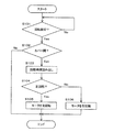
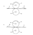
図4は、外力による加熱ローラ51の回転が検知された場合に制御部100が行う処理の一例を示したフローチャートである。また、図5は、モータ56を駆動させて加熱ローラ51及び加圧ローラ52を回転させる際の態様を示した模式図である。
FIG. 4 is a flowchart illustrating an example of processing performed by the
回転検知センサ10により加熱ローラ51の回転が検知された場合には(ステップS101でYes)、開閉検知センサ11からの入力信号に基づいて、開閉カバー22が開状態であるか否かが判定される(ステップS102)。このとき、開閉カバー22が閉状態であれば(ステップS102でNo)、定着部5に詰まった記録紙をユーザが引っ張ることはできないため、他の要因により加熱ローラ51が回転したと判断することができる。したがって、このような場合には、モータ56の駆動が制御されることなく処理が終了する。
When rotation of the
開閉カバー22が開状態であれば(ステップA102でYes)、そのとき使用されている記録紙のサイズに対応する回転時間又は記録紙のサイズに関係のない一定の回転時間がメモリ12から読み出される(ステップS103)。図5(a)に示すように、記録紙Pが矢印A1の方向に引っ張られ、加熱ローラ51の回転方向が左回転と検知された場合には(ステップS104でYes)、モータ56が同方向に回転駆動されることにより(ステップS105)、加熱ローラ51が自動的に左回転する。一方、図5(b)に示すように、記録紙Pが矢印A2の方向に引っ張られ、加熱ローラ51の回転方向が右回転と検知された場合には(ステップS104でNo)、モータ56が同方向に回転駆動されることにより(ステップS106)、加熱ローラ51が自動的に右回転する。
If the open /
上記の例では、回転方向検知部102により検知される加熱ローラ51の回転方向と、モータ56を回転駆動させる方向とが同一の場合について説明した。ただし、上述の通りギア55の数を変更した場合などには、回転方向検知部102により検知される加熱ローラ51の回転方向と、モータ56を回転駆動させる方向とが逆方向になる場合もある。
In the above example, the case where the rotation direction of the
本実施形態では、モータ56の駆動力とは異なる外力により加熱ローラ51及び加圧ローラ52が回転した場合に、その回転方向に加熱ローラ51及び加圧ローラ52をさらに回転させることができる。すなわち、ユーザが詰まった記録紙を取り除くのに適した方向を判断し、その方向に記録紙を引っ張った場合には、その方向への加熱ローラ51及び加圧ローラ52の回転をアシストすることができる。これにより、詰まった記録紙を取り除くのに適した方向とは逆方向に加熱ローラ51及び加圧ローラ52が回転して、記録紙がかえって取り除きにくくなるのを効果的に防止することができるので、詰まった記録紙をより良好に取り除くことができる。
In the present embodiment, when the
以上の実施形態では、本発明がプリンタに適用された場合について説明したが、このような構成に限らず、本発明は、定着部を備えた画像形成装置であれば、プリンタ以外に、複写機などの他の画像形成装置にも適用可能である。 In the above embodiment, the case where the present invention is applied to a printer has been described. However, the present invention is not limited to such a configuration, and the present invention is not limited to a printer, as long as the image forming apparatus includes a fixing unit. The present invention can also be applied to other image forming apparatuses.
1 画像形成装置
5 定着部
10 回転検知センサ
11 開閉検知センサ
12 メモリ
51 加熱ローラ
52 加圧ローラ
53 回転軸
54 回転軸
55 ギア
56 モータ
57 駆動軸
58 反射板
100 制御部
101 駆動制御部
102 回転方向検知部
DESCRIPTION OF SYMBOLS 1
Claims (3)
上記加熱ローラ及び上記加圧ローラを回転させるために駆動される駆動部と、
上記駆動部の駆動力とは異なる外力による上記加熱ローラ及び上記加圧ローラの回転を検知する回転検知部と、
上記回転検知部の検知に基づいて上記駆動部を駆動させる駆動制御部とを備えたことを特徴とする定着装置。 A heating roller that is heated to a predetermined temperature; and a pressure roller that is in contact with the heating roller at a predetermined pressure, and the recording paper onto which toner is transferred passes between the heating roller and the pressure roller. A fixing device for fixing the toner,
A drive unit driven to rotate the heating roller and the pressure roller;
A rotation detection unit that detects rotation of the heating roller and the pressure roller by an external force different from the driving force of the driving unit;
A fixing device comprising: a drive control unit that drives the drive unit based on detection by the rotation detection unit.
上記駆動制御部は、上記回転検知部により検知された方向に上記加熱ローラ及び上記加圧ローラが回転するように、上記駆動部を駆動させることを特徴とする請求項1に記載の定着装置。 The rotation detection unit can detect the direction in which the heating roller and the pressure roller rotate,
The fixing device according to claim 1, wherein the drive control unit drives the drive unit so that the heating roller and the pressure roller rotate in a direction detected by the rotation detection unit.
上記記録紙に転写されたトナーを定着させるための定着部に、請求項1又は2に記載の定着装置を備えたことを特徴とする画像形成装置。 An image forming apparatus that forms a toner image by developing an electrostatic latent image formed on a surface of a photoreceptor with toner, and forms an image by transferring the toner image to a recording paper.
An image forming apparatus comprising the fixing device according to claim 1 or 2 in a fixing unit for fixing the toner transferred onto the recording paper.
Priority Applications (1)
| Application Number | Priority Date | Filing Date | Title |
|---|---|---|---|
| JP2008114165A JP2009265331A (en) | 2008-04-24 | 2008-04-24 | Fixing device and image forming apparatus including the same |
Applications Claiming Priority (1)
| Application Number | Priority Date | Filing Date | Title |
|---|---|---|---|
| JP2008114165A JP2009265331A (en) | 2008-04-24 | 2008-04-24 | Fixing device and image forming apparatus including the same |
Publications (1)
| Publication Number | Publication Date |
|---|---|
| JP2009265331A true JP2009265331A (en) | 2009-11-12 |
Family
ID=41391274
Family Applications (1)
| Application Number | Title | Priority Date | Filing Date |
|---|---|---|---|
| JP2008114165A Pending JP2009265331A (en) | 2008-04-24 | 2008-04-24 | Fixing device and image forming apparatus including the same |
Country Status (1)
| Country | Link |
|---|---|
| JP (1) | JP2009265331A (en) |
Cited By (4)
| Publication number | Priority date | Publication date | Assignee | Title |
|---|---|---|---|---|
| JP2012098398A (en) * | 2010-10-29 | 2012-05-24 | Brother Ind Ltd | Image forming device |
| JP2012176827A (en) * | 2011-02-25 | 2012-09-13 | Ricoh Co Ltd | Jam processing assisting device and image forming apparatus with the same |
| JP2013190582A (en) * | 2012-03-13 | 2013-09-26 | Kyocera Document Solutions Inc | Image forming apparatus |
| WO2019130776A1 (en) * | 2017-12-27 | 2019-07-04 | 京セラドキュメントソリューションズ株式会社 | Fixing device and image forming device |
-
2008
- 2008-04-24 JP JP2008114165A patent/JP2009265331A/en active Pending
Cited By (10)
| Publication number | Priority date | Publication date | Assignee | Title |
|---|---|---|---|---|
| JP2012098398A (en) * | 2010-10-29 | 2012-05-24 | Brother Ind Ltd | Image forming device |
| US8761647B2 (en) | 2010-10-29 | 2014-06-24 | Brother Kogyo Kabushiki Kaisha | Image forming apparatus having a cleaning mode control section |
| JP2012176827A (en) * | 2011-02-25 | 2012-09-13 | Ricoh Co Ltd | Jam processing assisting device and image forming apparatus with the same |
| JP2013190582A (en) * | 2012-03-13 | 2013-09-26 | Kyocera Document Solutions Inc | Image forming apparatus |
| WO2019130776A1 (en) * | 2017-12-27 | 2019-07-04 | 京セラドキュメントソリューションズ株式会社 | Fixing device and image forming device |
| CN110199227A (en) * | 2017-12-27 | 2019-09-03 | 京瓷办公信息系统株式会社 | Fixing device and image forming apparatus |
| JPWO2019130776A1 (en) * | 2017-12-27 | 2020-01-16 | 京セラドキュメントソリューションズ株式会社 | Fixing device and image forming device |
| US11009824B2 (en) | 2017-12-27 | 2021-05-18 | Kyocera Document Solutions Inc. | Fixing device rotating fixing member or pressing member while medium is extracted and image forming apparatus including the same |
| EP3734369A4 (en) * | 2017-12-27 | 2021-11-10 | KYOCERA Document Solutions Inc. | FIXING DEVICE AND IMAGE FORMING DEVICE |
| CN110199227B (en) * | 2017-12-27 | 2022-06-03 | 京瓷办公信息系统株式会社 | Fixing device and image forming apparatus |
Similar Documents
| Publication | Publication Date | Title |
|---|---|---|
| CN100568119C (en) | Fixing device | |
| JP5794470B2 (en) | Image forming apparatus | |
| JP6049298B2 (en) | Image forming apparatus and control method thereof | |
| JP2001201987A (en) | Image forming device | |
| JP5300518B2 (en) | Image forming apparatus | |
| JP4446002B2 (en) | Paper transport device, image forming apparatus including the same, paper transport method, paper transport program, and computer-readable recording medium recording the program | |
| JP5153285B2 (en) | Image forming apparatus | |
| JP2009084038A (en) | Image forming device and method for detecting paper | |
| JP6388159B2 (en) | Image forming apparatus | |
| JP4445979B2 (en) | Image forming apparatus and method for restarting the same | |
| JP2787505B2 (en) | Paper jam detector | |
| JP5325505B2 (en) | Image forming apparatus | |
| JP2009265327A (en) | Fixing device and image forming apparatus including the same | |
| JP2008209536A (en) | Image forming apparatus | |
| JP4638929B2 (en) | Image forming apparatus | |
| JP2010014807A (en) | Image forming apparatus | |
| JP2010241569A (en) | Image forming device | |
| JP5768584B2 (en) | Fixing apparatus, image forming apparatus, fixing control method, and fixing control program | |
| JP5820764B2 (en) | Image forming apparatus | |
| JP2009271203A (en) | Cover open/close detection mechanism and image forming apparatus equipped with the same | |
| JP2017227759A (en) | Sheet conveyance device and image formation apparatus | |
| JP6318648B2 (en) | Image forming apparatus and image forming method | |
| JP5810030B2 (en) | Image forming apparatus | |
| JP2005195650A (en) | Transfer device | |
| JP6512409B2 (en) | Fixing device and image forming apparatus provided with the fixing device |