JP2009270331A - Connecting structure of snow-melting block - Google Patents
Connecting structure of snow-melting block Download PDFInfo
- Publication number
- JP2009270331A JP2009270331A JP2008121533A JP2008121533A JP2009270331A JP 2009270331 A JP2009270331 A JP 2009270331A JP 2008121533 A JP2008121533 A JP 2008121533A JP 2008121533 A JP2008121533 A JP 2008121533A JP 2009270331 A JP2009270331 A JP 2009270331A
- Authority
- JP
- Japan
- Prior art keywords
- snow
- block
- water
- elastic material
- melting
- Prior art date
- Legal status (The legal status is an assumption and is not a legal conclusion. Google has not performed a legal analysis and makes no representation as to the accuracy of the status listed.)
- Ceased
Links
- 238000002844 melting Methods 0.000 title claims abstract description 69
- XLYOFNOQVPJJNP-UHFFFAOYSA-N water Substances O XLYOFNOQVPJJNP-UHFFFAOYSA-N 0.000 claims abstract description 84
- 239000013013 elastic material Substances 0.000 claims abstract description 68
- 239000007921 spray Substances 0.000 claims description 12
- 230000000630 rising effect Effects 0.000 claims description 10
- 230000008878 coupling Effects 0.000 claims 1
- 238000010168 coupling process Methods 0.000 claims 1
- 238000005859 coupling reaction Methods 0.000 claims 1
- 238000010276 construction Methods 0.000 abstract description 6
- 238000007789 sealing Methods 0.000 abstract 2
- 230000006378 damage Effects 0.000 abstract 1
- 238000009434 installation Methods 0.000 description 28
- 239000000463 material Substances 0.000 description 13
- 239000002184 metal Substances 0.000 description 7
- 230000004308 accommodation Effects 0.000 description 6
- 238000002347 injection Methods 0.000 description 6
- 239000007924 injection Substances 0.000 description 6
- 238000003780 insertion Methods 0.000 description 5
- 230000037431 insertion Effects 0.000 description 5
- 239000000853 adhesive Substances 0.000 description 3
- 230000001070 adhesive effect Effects 0.000 description 3
- 238000013461 design Methods 0.000 description 3
- 238000004891 communication Methods 0.000 description 2
- 230000005489 elastic deformation Effects 0.000 description 2
- 230000013011 mating Effects 0.000 description 2
- JOYRKODLDBILNP-UHFFFAOYSA-N Ethyl urethane Chemical compound CCOC(N)=O JOYRKODLDBILNP-UHFFFAOYSA-N 0.000 description 1
- 101000927062 Haematobia irritans exigua Aquaporin Proteins 0.000 description 1
- 238000013459 approach Methods 0.000 description 1
- 239000003795 chemical substances by application Substances 0.000 description 1
- 238000007599 discharging Methods 0.000 description 1
- 230000001747 exhibiting effect Effects 0.000 description 1
- 239000000835 fiber Substances 0.000 description 1
- 239000003673 groundwater Substances 0.000 description 1
- 230000002262 irrigation Effects 0.000 description 1
- 238000003973 irrigation Methods 0.000 description 1
- 238000012423 maintenance Methods 0.000 description 1
- 238000000034 method Methods 0.000 description 1
- 230000002093 peripheral effect Effects 0.000 description 1
- 239000011347 resin Substances 0.000 description 1
- 229920005989 resin Polymers 0.000 description 1
- 239000000126 substance Substances 0.000 description 1
Images






Landscapes
- Cleaning Of Streets, Tracks, Or Beaches (AREA)
Abstract
Description
本発明は、消雪用散水ノズルを備えた消雪ブロックの連結構造に関するものである。 TECHNICAL FIELD The present invention relates to a snow-breaking block connecting structure provided with a snow-sprinkling water spray nozzle.
この種消雪ブロックの連結構造としては、図16に示すように散水ノズルに水などを供給する散水管20を具備した消雪ブロック21の両端の突き合せ面22の一方に、散水管20の一側端部を延長突出させて挿入筒部23を形成し、他方に、この挿入筒部23を挿入接続可能な接続筒部24を形成した構成として、複数の消雪ブロック21を縦列した上でこの挿入筒部23と接続筒部24とをオス・メス接続して連結する構造(例えば、特許文献1参照。)や、図17に示すように複数縦列した消雪ブロック21の両端の突き合せ面22間に別部品のジョイント管25を架設状態に挿入取付することで各散水管20同士を接続して連結する構造(例えば、特許文献2参照。)が知られている。
As shown in FIG. 16, this kind of snow-melting block is connected to one end of the
上記のようなオス・メス接続構造やジョイント管25を用いる接続構造は、いずれも、一方の消雪ブロック21に対して他方の消雪ブロック21を横移動させて挿入筒部23若しくはジョイント管25を挿入接続する(図16,図17参照。)。
As for the connection structure using the male / female connection structure and the
しかしながら、この接続作業は、先に据え付けた一方の消雪ブロック21に対して他方の消雪ブロック21をできるだけ水平にして横移動させながら管(筒)同士の位置合せと挿入接続とを行うのであるが、この際、一方の消雪ブロック21に対して他方の消雪ブロック21を水平にしすぎるとブロック底面を設置面に引きずってしまうし、かといって他方の消雪ブロック21を傾かせすぎると管同士が接続しづらかったり管が損傷してしまったりする場合があるため、慎重を要する非常に厄介な作業であった。
However, in this connection work, the pipes (cylinders) are aligned and inserted and connected while moving the other
また、この連結構造をもって完成した消雪設備は、縦列状態に設置した各消雪ブロック21を横移動させて挿入筒部23若しくはジョイント管25を接続解除することが不可能となるために、破損した或いは経年劣化した消雪ブロック21を部分的に交換・修復する必要が生じた場合には、交換対象の消雪ブロック21の両端部とこれに隣接する消雪ブロック21の端部との境目を接続した管ごとコンクリートカッターで切断して交換対象の消雪ブロック21を吊り上げ撤去した後、撤去した消雪ブロック21の両側に隣接する消雪ブロック21の端部を解体して散水管20を露出させ、次いで、この露出した各散水管20間に新設管材を連結してその周囲にコンクリートを打設したり、あるいは露出した各散水管20間に新しい消雪ブロックを据え付けて散水管20を接続すると共に隣接する消雪ブロック21端部の解体部をコンクリート打設して補修したりするような大掛かりなメンテナンス工事を要するものであった。
In addition, the snow extinguishing equipment completed with this connecting structure is damaged because it is impossible to disconnect the
本発明は、このような従来の消雪ブロックの連結構造の問題点を見出し、これを解決しようとするためのもので、消雪ブロックを横移動させることなく容易に設置可能であると共に散水路の接続も容易に可能であり、また破損或いは劣化した消雪ブロックや止水用弾性材の交換に際して、隣接する消雪ブロックの端部の解体を伴わずに容易に交換可能となる画期的な消雪ブロックの連結構造を提供するものである。 The present invention has been made in order to find out the problems of the conventional snow-melting block connecting structure and to solve the problems, and can be easily installed without laterally moving the snow-blocking block and the watering channel. Can be easily connected, and can be easily replaced without dismantling the end of the adjacent snow-blocking block when replacing a damaged or deteriorated snow-blocking block or elastic material for water-stopping A snow linking block connecting structure is provided.
添付図面を参照して本発明の要旨を説明する。 The gist of the present invention will be described with reference to the accompanying drawings.
散水路1を有する消雪ブロック2の両端の突き合せ面3同士を突き合せて複数の消雪ブロック2を縦列状態に連結することで、この突き合せ面3に臨設する前記各散水路1の端部1A同士が合致して各散水路1が連通接続する消雪ブロックの連結構造であって、前記各散水路1同士の接続に、前記突き合せ面3より外方へ突設する接続管を用いることなく、縦列状態とする一方の消雪ブロック2に対して他方の消雪ブロック2を降下載置した際に、一方の消雪ブロック2の底部と他方の消雪ブロック2の底部の間に掛け渡し状態に敷設されて一方の消雪ブロック2と他方の消雪ブロック2の突き合せ面3同士を突き合せ状態に位置決め保持する位置決めプレート4を設けると共に、この位置決めプレート4により突き合せ状態に保持された各消雪ブロック2の突き合せ面3間に、前記各散水路1の端部1Aを囲繞するように止水用弾性材5を配設固定して、各散水路1同士を止水状態に接続する構造としたことを特徴とする消雪ブロックの連結構造に係るものである。
The
また、前記消雪ブロック2は、送水管を埋設せずに前記散水路1を具備する形状にコンクリートで一体成形したものを採用したことを特徴とする請求項1記載の消雪ブロックの連結構造に係るものである。
2. The snow squeeze block connecting structure according to
また、前記位置決めプレート4は、一方の消雪ブロック2に対して他方の消雪ブロック2を降下載置した際に、この他方の消雪ブロック2の底部に凹凸係合して他方の消雪ブロック2を位置決め保持する構成としたことを特徴とする請求項1,2のいずれか1項に記載の消雪ブロックの連結構造に係るものである。
The
また、前記位置決めプレート4の凹凸係合面に、他方の消雪ブロック2が降下するにしたがってこの他方の消雪ブロック2の突き合せ面3を一方の消雪ブロック2の突き合せ面3に対して接近する方向に誘導案内するテーパ面状の案内面部6を設けたことを特徴とする請求項3記載の消雪ブロックの連結構造に係るものである。
Further, as the other
また、前記位置決めプレート4の両端部に立ち上がり部4Aを設けて、この各立ち上がり部4A間に前記消雪ブロック2を降下載置することで、各立ち上がり部4Aにより消雪ブロック2の位置ズレを防止する構成としたことを特徴とする請求項1〜4のいずれか1項に記載の消雪ブロックの連結構造に係るものである。
Further, the rising
また、前記止水用弾性材5は、前記散水路1の端部1Aより径大なリング状に構成したことを特徴とする請求項1〜5のいずれか1項に記載の消雪ブロックの連結構造に係るものである。
Moreover, the said elastic material for
また、空気を注入することで膨張する構成の前記止水用弾性材5を採用し、この止水用弾性材5を、前記位置決めプレート4により突き合せ状態で位置決め保持された各消雪ブロック2の突き合せ面3間に、前記各散水路1の端部1Aを囲繞するようにして配設すると共に、空気を注入して膨張させることでこの止水用弾性材5を各突き合せ面3に圧接せしめて、この止水用弾性材5により各散水路1の端部1A間を止水状態とする構成としたことを特徴とする請求項1〜6のいずれか1項に記載の消雪ブロックの連結構造に係るものである。
Further, each of the snow-
本発明は上述のように構成したから、単に一方の消雪ブロックに対し他方の消雪ブロックを降下載置するだけで位置決めプレートにより消雪ブロック同士の突き合せ面が突き合せ状態に位置決め保持されるために、縦列状態とする一方の消雪ブロックに対して他方の消雪ブロックを横移動することなく設置可能で、この消雪ブロックの設置作業が著しく容易に行われることになり、しかも、位置決めプレートにより突き合せ状態に保持された各消雪ブロックの突き合せ面間に、各散水路の端部を囲繞するように止水用弾性材を配設固定して、各散水路同士を止水状態に接続する構造としたから、この止水構造は簡易に施工可能な構成であると共に、各散水路同士を精度良く位置合せせずともこの止水用弾性材により各散水路間が止水状態に維持されて接続されるので、散水路同士の接続作業も容易に可能となり、その上、消雪設備完成後に破損或いは劣化した消雪ブロックを交換する必要性が生じた場合には、管の切断や隣接する消雪ブロック端部の解体などを伴うことなく交換対象の消雪ブロックだけを上昇移動させて撤去可能となるため、従来構造のような大掛かりな工事を要することなく容易に交換可能となり、同様にして破損或いは劣化した止水用弾性材も容易に交換可能であるのでメンテナンス性が著しく向上することになるなど、極めて実用性に秀れた画期的な消雪ブロックの連結構造となる。 Since the present invention is configured as described above, the abutment surfaces of the snow-melting blocks are positioned and held in the butted state by the positioning plate simply by lowering and placing the other snow-melting block on one snow-melting block. Therefore, it is possible to install without moving the other snow-dissipating block laterally with respect to one snow-dissipating block that is in a tandem state, and the installation work of this snow-dissipating block will be performed remarkably easily, An elastic material for water stop is disposed and fixed between the butt surfaces of each snow-fighting block held in a butt state by the positioning plate so as to surround the end of each water irrigation path, thereby stopping the water sprinkling paths. Since the structure is connected to the water state, the water stop structure can be easily constructed, and the water stop paths are stopped by the elastic material for water stop even without accurately aligning the water spray paths. Maintain water condition In addition, it is possible to easily connect the sprinkling channels. In addition, if there is a need to replace a snow block that has been damaged or deteriorated after completion of the snow extinguishing facility, Because it is possible to lift and remove only the snow block to be exchanged without disassembling the end of the adjacent snow block, etc., it can be easily replaced without requiring large construction like the conventional structure, In the same way, damaged or deteriorated water-stopping elastic materials can be easily replaced, so the maintainability is remarkably improved, and the groundbreaking snow-melting block connection structure is extremely excellent in practicality. .
また、請求項2記載の発明においては、突き合せ面より外方へ接続管が突設しない構成の消雪ブロックを簡易に設計実現可能であると共に、この消雪ブロックは、一般的な消雪ブロックに比して送水管を埋設しない分コストを削減できることになるなど、一層実用性に秀れた消雪ブロックの連結構造となる。
In the invention described in
また、請求項3記載の発明においては、消雪ブロックの位置決め作用を確実に発揮する位置決めプレートを簡易構成により容易に設計実現可能となる一層実用性に秀れた消雪ブロックの連結構造となる。
Further, in the invention described in
また、請求項4記載の発明においては、据付に際して多少ラフな位置に消雪ブロックを降下させても、位置決めプレートの凹凸係合面の案内面部により他方の消雪ブロックが降下するにしたがってこの他方の消雪ブロックの突き合せ面が一方の消雪ブロックの突き合せ面に対して接近する方向に誘導案内されるので、一層設置作業が簡易に行われる極めて実用性に秀れた消雪ブロックの連結構造となる。
In the invention according to
また、請求項5記載の発明においては、消雪ブロックの位置ズレが良好に防止される秀れた消雪ブロックの連結構造となり、更にこの発明と前記請求項3記載の発明とを併用することで、一層秀れた消雪ブロックの位置決め作用が得られることになる。
Moreover, in invention of
また、請求項6記載の発明においては、散水路の端部より径大なリング状の止水用弾性材により確実に散水路同士を止水状態に接続できる一層実用性に秀れた消雪ブロックの連結構造となる。
Further, in the invention described in
また、請求項7記載の発明においては、突き合せ状態で位置決め保持された各消雪ブロックの突き合せ面間に、止水用弾性材を簡易に配設固定可能となる極めて施工性に秀れた消雪ブロックの連結構造となる。 Further, in the invention according to claim 7, the water stop elastic material can be easily disposed and fixed between the butting surfaces of the snow-melting blocks that are positioned and held in the butting state. It becomes the connection structure of the snow-melting block.
好適と考える本発明の実施形態(発明をどのように実施するか)を、図面に基づいて本発明の作用を示して簡単に説明する。 Embodiments of the present invention that are considered suitable (how to carry out the invention) will be briefly described with reference to the drawings, illustrating the operation of the present invention.
例えば、道路などに設けた長溝内に、消雪ブロック2を複数縦列状態に並べて各消雪ブロック2両端の突き合せ面3同士を突き合せることで、この各突き合せ面3に臨設する各散水路1の端部1A同士を合致させて各散水路1を連通接続する。
For example, in a long groove provided on a road or the like, a plurality of snow-dissipating
更に具体的には、本発明では、前記各散水路1同士の接続に、前記突き合せ面3より外方へ突設する接続管を用いることなく、縦列状態とする一方の消雪ブロック2に対して他方の消雪ブロック2を降下載置し、この際、一方の消雪ブロック2の底部と他方の消雪ブロック2の底部の間に掛け渡し状態に敷設した位置決めプレート4により一方の消雪ブロック2と他方の消雪ブロック2の突き合せ面3同士を突き合せ状態に位置決め保持すると共に、この位置決めプレート4により突き合せ状態に保持された各消雪ブロック2の突き合せ面3間に、前記各散水路1の端部1Aを囲繞するように止水用弾性材5を配設固定して各散水路1同士を止水状態に接続する構造とする。
More specifically, in the present invention, the connection between the water sprinkling
従って、例えば、予め位置決めプレート4を敷設しておいて、この位置決めプレート4上に一方の消雪ブロック2を載置し、続いて他方の消雪ブロック2を設置位置にその略真上方向からクレーンなどを利用して降下載置させるだけで縦列する消雪ブロック2同士の突き合せ面3が突き合せ状態に位置決め保持されるので、この消雪ブロック2の設置作業が極めて容易に行われることになる。
Therefore, for example, a
また、位置決めプレート4上には、消雪ブロック2を載置し易い上に安定的に載置でき、しかも、位置決めプレート4によって消雪ブロック2の据付位置が大きく底上げされるようなこともないため、この位置決めプレート4を設置場所と消雪ブロック2の間に敷設する構成でありながら、消雪ブロック2の設置作業が容易に行われて作業性に秀れる。
In addition, the
また、散水路1同士の止水構造(接続構造)についても、突き合せ状態に保持された各消雪ブロック2の突き合せ面3間に、前記各散水路1の端部1Aを囲繞するように止水用弾性材5を配設固定するだけの構造であるから、簡易に施工可能な構造であると共に、消雪ブロック2を横移動させて管(筒)同士を挿入接続する場合のような高い位置合せ精度も不要で、この散水路1同士の接続作業が極めて容易に行われることとなる。
Moreover, also about the water stop structure (connection structure) of the
また、消雪設備完成後に破損或いは劣化した消雪ブロック2を交換する必要性が生じた場合にも、管の切断や隣接する消雪ブロック2端部の解体などを伴うことなくクレーンなどを利用して上昇移動させることだけで撤去可能であるし、この撤去スペースに設置する新たな消雪ブロック2も横移動を伴うことなく降下載置させて設置可能であるため、例えば新たな止水用弾性材5と共に容易に交換可能である。
In addition, when it is necessary to replace a damaged or deteriorated snow-
また、同様にして、破損或いは劣化した止水用弾性材5についても容易に交換可能である。
Similarly, the water-stopping
また、例えば、前記位置決めプレート4は、一方の消雪ブロック2に対して他方の消雪ブロック2を降下載置した際に、この他方の消雪ブロック2の底部に凹凸係合して他方の消雪ブロック2を位置決め保持する構成とすれば、凹凸係合により確実に消雪ブロック2を位置決め可能であると共に、この位置決めプレート4と消雪ブロック2の凹凸係合構造は簡易な構造であるため容易に設計実現可能である。
Further, for example, when the other
更に、例えば、前記位置決めプレート4の凹凸係合面に、他方の消雪ブロック2が降下するにしたがってこの他方の消雪ブロック2の突き合せ面3を一方の消雪ブロック2の突き合せ面3に対して接近する方向に案内移動させて夫々の突き合せ面3同士を突き合せ状態とし得るテーパ面状の案内面部6を設ければ、据付に際して多少ラフな位置に消雪ブロック2を降下させても、位置決めプレート4との凹凸係合により適正な据付位置に誘導案内されるので、一層設置作業性に秀れることになる。
Further, for example, as the other
本発明の具体的な実施例1について図1〜図7に基づいて説明する。 A first embodiment of the present invention will be described with reference to FIGS.
本実施例は、図1,図2に示すように、消雪ブロック2と、複数の消雪ブロック2の突き合せ面3同士を突き合せ状態に位置決め保持する位置決めプレート4と、この位置決めプレート4によって突き合せ状態に保持された各消雪ブロック2の突き合せ面3間に配設固定する止水用弾性材5とを用いた消雪ブロック2の連結構造に係るものである。
In this embodiment, as shown in FIGS. 1 and 2, the
具体的には、本実施例の消雪ブロック2は、図1〜図3に示すようなコンクリート製の細長い角形体であって、その上面には長手方向に間隔を置いて散水ノズル7を複数並設状態に具備し、長手方向の両端部には鉛直面状の前記突き合せ面3を具備している。
Specifically, the snow-dissipating
また、この消雪ブロック2は、前記各散水ノズル7に地下水などを供給するための散水路1をこの消雪ブロック2の長手方向に沿って埋設状態に設けて、この散水路1の両端部1Aが前記各突き合せ面3に臨設(開口)する構成としているが、この散水路1は管などを消雪ブロック2内に埋め込んで形成するのではなく、本実施例では、散水路1を有する形状にコンクリートで一体成形した消雪ブロック2を採用している。
In addition, the snow-dissipating
また、この消雪ブロック2は、図3に示すように両端部の底部(底面)に後述の位置決めプレート4が凹凸係合する係合凹部9を一体的に凹設すると共に、両端の各突き合せ面3には、図1に示すように前記散水路1の端部1Aの周囲をこの散水路1の中心(軸心)と同心形状であって散水路1より径大な多角形(図面では六角形)状に凹設して、この凹設部を後述の止水用弾性材5が収容される収容凹部10としている。
In addition, as shown in FIG. 3, the snow-dissipating
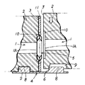
本実施例の位置決めプレート4は、金属製の方形薄板材で構成して、一方の消雪ブロック2の底部と他方の消雪ブロック2の底部の間に掛け渡し状態に敷設される構成としている。即ち、この位置決めプレート4を構成する方形状板材の板面上に、二体の消雪ブロック2の端部底面を前記突き合せ面3を付き合せた状態で載置し得るように構成している。
The
また、この位置決めプレート4と、消雪ブロック2の端部との位置決め構造は、図1,図2に示すように位置決めプレート4の対向二辺部を略直角上方へ短めに折曲して断面コ字板状とし、この対向二辺の立ち上がり部4Aが、載置した消雪ブロック2の下部左右両側部に沿設して消雪ブロック2の長さ方向と直交する方向への位置ズレを防止するガイド部4Aとして機能する構成としている。
Further, the positioning structure of the
更に、位置決めプレート4の上面の両側部に係合凸部8を突設し、この係合凸部8に、消雪ブロック2の底面に設けた前記係合凹部9を凹凸係合して位置決めプレート4上に消雪ブロック2の端部を載置することで、位置決めプレート4に対し消雪ブロック2が位置決め保持される構造としている。
Further, engaging
また、この位置決めプレート4上に二体の消雪ブロック2の端部を突き合せ状態に載置して夫々の係合凹部9を各係合凸部8に凹凸係合した際、図5,図6に示すように、この二体の消雪ブロック2が各々の突き合せ面3間に10mm程の隙間を生じた近接状態で位置決め保持されるように、位置決めプレート4上に設ける係合凸部8の位置と消雪ブロック2端部の底部に設ける係合凹部9の位置とのいずれか一方若しくは双方を設定構成している。
Further, when the end portions of the two snow extinguishing blocks 2 are placed in contact with each other on the
また、この位置決めプレート4の係合凸部8に、一方の消雪ブロック2に対して他方の消雪ブロック2を降下載置する際に、他方の消雪ブロック2が降下するにしたがってこの他方の消雪ブロック2の突き合せ面3を一方の消雪ブロック2の突き合せ面3に対して接近する方向に誘導案内するテーパ面状の案内面部6を設けている。
Further, when the other snow-dissipating
具体的には、図1,図2,図6に示すように位置決めプレート4の一側の係合凸部8は平面視略正円形状に形成し、他側の係合凸部8は平面視長円形状に形成し、この他側の係合凸部8にだけ前記案内面部6を設けている。
Specifically, as shown in FIGS. 1, 2, and 6, the engaging
更に詳しくは、図4に示すように長円形状を呈する他側の係合凸部8の、一側の係合凸部8との対向側面を後傾斜するテーパ面に形成してこのテーパ面を前記案内面部6としている。尚、案内面部6を有する係合凸部8と案内面部6のない係合凸部8の形状を異ならせたのは、現場作業者が位置決めプレート4をどの向きで載置すべきかを簡単に確認できるようにするためである。
More specifically, as shown in FIG. 4, the side surface of the other side engaging
一方、消雪ブロック2の両端部の底部に設ける前記係合凹部9も、一側の係合凹部9は平断面略円形状の凹部に形成し、他側の係合凹部9は平断面長円形状の凹部に形成し、この他側の係合凹部9は、一側の係合凹部9との対向側面を後傾斜するテーパ面に形成してこのテーパ面が前記他側の係合凸部8の案内面部6に係合する構成としている。
On the other hand, the engagement recesses 9 provided at the bottoms of both ends of the snow-
また、この他側の係合凹部9の大きさを、他側の係合凸部8よりやや大きく設定して、この他側の係合凹部9と他側の係合凸部8とが凹凸係合した際に隙間を生じるように構成し、これにより凹凸係合時でも他方の消雪ブロック2を若干移動可能として、据付位置の微調整を行えるようにしている。
Further, the size of the
即ち、本実施例では、案内面部6の誘導によって消雪ブロック2が完全に正しい据付位置に是正されるような構成ではなく、最終的な据付位置調整を要する構成である。
In other words, in this embodiment, the
このように他側の係合凹部9と他側の係合凸部8とが隙間を生じて係合し、且つ案内面部6が消雪ブロック2を正しい据付位置まで誘導しない構成としたことで、例えば、施工完了後に不具合を生じた消雪ブロック2を交換する場合に、交換対象の消雪ブロック2をクレーンなどを利用して略真上に上昇させることによって係合凹部9と係合凸部8との凹凸係合を簡単に係脱させて撤去することができるので、メンテナス性に秀れる。
In this way, the
本実施例の止水用弾性材5は、ゴム製とする共に、図1に示すように前記散水路1の端部1Aより径大な円形リング状に構成している。
The water stop
また、この止水用弾性材5は、空気を注入することで膨張する断面角形のチューブ構造体とし、この止水用弾性材5を、前記位置決めプレート4により突き合せ状態で位置決め保持された消雪ブロック2の突き合せ面3間に前記各散水路1の端部1Aを囲繞するようにして配設し、空気を注入して膨張させることでこの止水用弾性材5を各突き合せ面3に圧着せしめて、この止水用弾性材5により各散水路1の端部1A間を止水状態とできる構成としている。
Further, the water-stopping
また、この止水用弾性材5は、突き合せ面3の前記収容凹部10に収容して仮止め状態としておくことができるように、この止水用弾性材5と収容凹部10の外径寸法を設定構成している。従って、これにより設置完了した一方の消雪ブロック2の収容凹部10に、引き続いて降下載置する他方の消雪ブロック2が設置完了するまで止水用弾性材5を仮止めしておくことができるので、施工作業を極めて容易に且つ効率良く行うことができる構成としている。
Further, the outer diameter of the water-stopping
また、この止水用弾性材5は、空気注入用の注入部5Aを備えた構成とし、一方の消雪ブロック2と他方の消雪ブロック2とを突き合せ状態に位置決めした後、注入部5Aから空気を注入して止水用弾性材5を膨張させることができるように構成している。
Further, the water-stopping
具体的には、消雪ブロック2の突き合せ面3に前記収容凹部10と連設状態にして溝部14を設け、この溝部14に、止水用弾性材5の外周縁部から外方へ長く突設した注入部5Aを収容して消雪ブロック2外へ露出させ、この溝部14を介して消雪ブロック2外に露出する注入部5Aから空気を注入し得るように構成している。
Specifically, a
また、本実施例では、空気の注入により膨張した止水用弾性材5を突き合せ面3に接着する構成としている。
In the present embodiment, the water-stopping
具体的には、止水用弾性材5の両側面に予め接着剤13を塗布しておき、空気の注入によって止水用弾性材5が膨張すると、その両側面が突き合せ面3(収容凹部10)に圧接し、この圧接(密着)状態が接着剤13の硬化により維持されて、確実な止水性を発揮する構成としている。
Specifically, the adhesive 13 is applied in advance to both side surfaces of the water-stopping
次に、本実施例の施工手順を説明する。 Next, the construction procedure of a present Example is demonstrated.
設置場所の所定位置に位置決めプレート4を載置し、この位置決めプレート4の一側に一方の消雪ブロック2を載置して凹凸係合させてこの一方の消雪ブロック2の収容凹部10に止水用弾性材5を仮止め収容し、続いて、位置決めプレート4の他側に他方の消雪ブロック2を載置して凹凸係合させて双方の消雪ブロック2の突き合せ面3を突き合せ、この各突き合せ面3間に止水用弾性材5を配設する。
The
具体的には、例えば、道路などに設けた長溝(設置場所)内に、予め位置決めプレート4を敷いておき、この位置決めプレート4の一側の略正円形の係合凸部8に消雪ブロック2の一側の平断面略円形状の係合凹部9を凹凸係合させて消雪ブロック2を載置し、この消雪ブロック2の突き合せ面3の収容凹部10に、両側面に接着剤13を付したリング状の止水用弾性材5を仮止め収容する。
Specifically, for example, a
続いて、設置済の一方の消雪ブロック2に対して他方の消雪ブロック2を降下させつつ、位置決めプレート4の他側の長円形状の係合凸部8に他方の消雪ブロック2の端部の底部の他側の平断面長円形状の係合凹部9を係合させると、係合凸部8の案内面部6と係合凹部9のテーパ面とが係合することにより、一方の消雪ブロック2に対して他方の消雪ブロック2が接近するように誘導案内されながら降下し(図4参照。)、この他方の消雪ブロック2が接地すると、夫々の突き合せ面3同士が近接突き合せ状態となり、この状態で双方の消雪ブロック2が位置決め保持される(図5,図6参照。)。
Subsequently, while lowering the other snow-
続いて、止水用弾性材5に空気を注入し膨張させて両側面を各突き合せ面3の収容凹部10に圧着させると、接着剤13の硬化により密着固定して双方の消雪ブロック2の各散水路1が止水用弾性材5により密閉止水状態となって接続される。
Subsequently, when air is injected into the
この作業を繰り返して、所望の消雪設備を完成させる。 This operation is repeated to complete a desired snow-melting facility.
また、本実施例による消雪設備完成後に、劣化した消雪ブロック2を交換する必要性が生じた場合には、交換対象の消雪ブロック2だけをクレーンなどを利用して略真上に上昇移動させることで撤去することができるし、撤去したところに新しい消雪ブロック2を降下載置して止水用弾性材5と共に簡単に設置施工可能である。また、同様にして止水用弾性材5のみを交換することも容易に行われる。
In addition, when it is necessary to replace the deteriorated
図中符号11は、縦列状態の各消雪ブロック2の突き合せ面3間の隙間に配設した目地材である。
In the figure, reference numeral 11 denotes a joint material disposed in the gap between the butting
尚、本実施例では、複数の消雪ブロック2をストレートな縦列状態に連結した場合を示したが、止水用弾性材5の弾性変形を利用して消雪ブロック2同士をカーブ(屈曲)させて縦列状態に連結することもできるし、設置場所の起伏等に応じて上下方向に屈曲させて縦列状態に連結することもできる。また、止水用弾性材5が弾性変形することにより消雪ブロック2の据付位置の微調整も容易に可能である。
In the present embodiment, a case where a plurality of snow-
また、位置決めプレート4は、金属製に限らず、ゴム製や化学繊維製や樹脂製や他の素材製でも良い。また、位置決めプレート4の立ち上がり部4Aの高さを更に高くすることで位置決め作用を向上させても良いし、立ち上がり部4Aを有しない構成としても良い。また、位置決めプレート4の係合凸部8の形状は、円形や長円形に限らず、角形や他の形状でも良い。
The
また、止水用弾性材5は、ゴム製に限らず、スポンジ製やウレタン製や他の弾性変形可能な素材製でも良い。また、止水用弾性材5の形状は、円形リング状に限らず、矩形状や多角形状などでも良く、要は散水路1を囲繞する形状であれば良い。また、止水用弾性材5の断面形状も、角形に限らず、円形でも良い。また、止水用弾性材5は、チューブ構造体でなくとも良いし、突き合せ面3に対して接着しなくとも良い。
Further, the water-stopping
本発明の具体的な実施例2について図8に基づいて説明する。 A second embodiment of the present invention will be described with reference to FIG.
本実施例は、前記実施例1において、消雪ブロック2の突き合せ面3の収容凹部10に、止水用弾性材5を位置決めするための補助金具12を設けた場合である。
In this embodiment, the auxiliary metal fitting 12 for positioning the water stop
具体的には、補助金具12は、円形リング状の止水用弾性材5の内径よりやや径小な円形リング状の金具で構成し、このリング状の補助金具12を散水路1の中心と同心位置に配して収容凹部10より突設状態に付設している。
Specifically, the auxiliary metal fitting 12 is constituted by a circular ring-shaped metal fitting that is slightly smaller in diameter than the inner diameter of the circular ring-shaped water-stopping
従って、この円形リング状に突設する補助金具12に、空気注入前の止水用弾性材5を掛止るようにして収容凹部10に収容できる構成とし、これにより収容凹部10での止水用弾性材5の仮止め状態が一層安定的となるようにしている。
Accordingly, the auxiliary metal fitting 12 protruding in the shape of a circular ring is configured to be able to be accommodated in the
他の構成は、前記実施例1と同様である。 Other configurations are the same as those of the first embodiment.
本発明の具体的な実施例3について図9,図10に基づいて説明する。 A specific third embodiment of the present invention will be described with reference to FIGS.
本実施例は、前記実施例1において、前記止水用弾性材5の形状を異ならせることで、図9に示すように消雪ブロック2をカーブした縦列状態に連結した場合を示している。
The present embodiment shows a case where the snow-stopping
具体的には、本実施例の止水用弾性材5は、図10に示すように、側面部をテーパ面形状に形成して、このテーパ状側面に消雪ブロック2の突き合せ面3を斜めから付き合わせて連結することで消雪ブロック2同士をカーブした縦列状態に据付している。尚、図10では注入部5Aを省略している。
Specifically, as shown in FIG. 10, the
また、本実施例では、詳しく図示していないが、消雪ブロック2の各突き合せ面3に散水路1の中心(軸心)と同心円形状の凹溝を形成し、この凹溝を止水用弾性材5を収納するための収容凹部10とした場合を示している。尚、この構成は、後述する実施例4,5についても同様である。
In this embodiment, although not shown in detail, a concave groove that is concentric with the center (axial center) of the
他の構成は、前記実施例1と同様である。 Other configurations are the same as those of the first embodiment.
本発明の具体的な実施例4について図11に基づいて説明する。 A fourth embodiment of the present invention will be described with reference to FIG.
本実施例も、消雪ブロック2をカーブした縦列状態に連結した場合を示している。
This embodiment also shows a case where the snow-
具体的には、本実施例では、一方の消雪ブロック2の収容凹部10に止水用弾性材5よりも軟質なクッション材15を収容し、このクッション材15を介して収容凹部10に止水用弾性材5を収容した構成として、クッション材15の弾性変形により一方の消雪ブロック2に対し他方の消雪ブロック2をカーブした縦列状態に据付している。
Specifically, in this embodiment, a
また、本実施例の止水用弾性材5は、断面円形のものを採用した場合を示している。
Moreover, the
他の構成は、前記実施例1と同様である。 Other configurations are the same as those of the first embodiment.
本発明の具体的な実施例5について図12に基づいて説明する。
A
本実施例も、消雪ブロック2をカーブした縦列状態に連結した場合を示している。
This embodiment also shows a case where the snow-
具体的には、前記実施例4において、クッション材15の止水用弾性材5に接する側の側面部をテーパ面形状に形成している。
Specifically, in the fourth embodiment, the side surface portion of the
従って、これによりクッション材15のテーパ状側面に止水用弾性材5を当接させると止水用弾性材5が突き合せ面3に対し斜設状態となるので、この止水用弾性材5に消雪ブロック2の突き合せ面3を斜めから突き合せて連結して、消雪ブロック2同士をカーブした縦列状態に据付している。
Accordingly, when the water-stopping
他の構成は、前記実施例1と同様である。 Other configurations are the same as those of the first embodiment.
本発明の具体的な実施例6について図13に基づいて説明する。 A sixth embodiment of the present invention will be described with reference to FIG.
本実施例は、前記実施例1において、前記収容凹部10の形状を異ならせることで、消雪ブロック2をカーブした縦列状態に連結した場合を示している。
This embodiment shows a case where the snow-removing
具体的には、本実施例では、消雪ブロック2の各突き合せ面3に散水路1の中心(軸心)と同心円形状の凹溝を形成してこの凹溝を収容凹部10とすると共に、図13に示すようにこの収容凹部10の溝底をテーパ面形状に形成している。
Specifically, in the present embodiment, a concave groove that is concentric with the center (axial center) of the
従って、このテーパ状の収容凹部10に収容した止水用弾性材5を介して消雪ブロック2を連結することにより、消雪ブロック2同士をカーブした縦列状態で据付している。
Therefore, by connecting the snow removal blocks 2 via the water stop
他の構成は、前記実施例1と同様である。 Other configurations are the same as those of the first embodiment.
本発明の具体的な実施例7について図14に基づいて説明する。 A specific embodiment 7 of the present invention will be described with reference to FIG.
本実施例は、前記実施例1において、位置決めプレート4による消雪ブロックの位置決め構造を改良した場合である。
The present embodiment is a case where the positioning structure of the snow removal block by the
具体的には、位置決めプレート4上に消雪ブロック2を載置した際、前記各立ち上がり部4Aを介してこの各立ち上がり部4Aの外側から貫通させた固定用ボルト16を消雪ブロック2の下部両側部に止着固定することで、位置決めプレート4に対し消雪ブロック2をより強固に位置決め固定した場合を示している。
Specifically, when the snow-
他の構成は、前記実施例1と同様である。 Other configurations are the same as those of the first embodiment.
本発明の具体的な実施例8について図15に基づいて説明する。
A
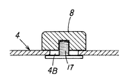
本実施例は、前記実施例1において、位置決めプレート4に設ける係合凸部8の位置を移動可能に構成した場合を示している。
The present embodiment shows a case where the position of the engaging
具体的には、位置決めプレート4に取付孔4Bを貫通形成し、この貫通孔4Bにこの貫通孔4Bより径小な取付ネジ17を下方から挿通してこの取付ネジ17の先端に前記係合凸部8を螺着した構成としている。
Specifically, a mounting
従って、この取付ネジ17を緩めることにより貫通孔4Bに取付ネジ17が許容される範囲内で係合凸部8の位置を移動可能で、再び取付ネジ17を締付することにより係合凸部8を位置決めできる構成としている。
Accordingly, by loosening the mounting
この係合凸部8の位置を移動させることにより、消雪ブロック2のカーブ施工等に対応できる構成としている。
By moving the position of this engagement
他の構成は、前記実施例1と同様である。 Other configurations are the same as those of the first embodiment.
尚、本発明は、実施例1〜8に限られるものではなく、各構成要件の具体的構成は適宜設計し得るものである。 In addition, this invention is not restricted to Examples 1-8, The specific structure of each component can be designed suitably.
1 散水路
1A 端部
2 消雪ブロック
3 突き合せ面
4 位置決めプレート
4A 立ち上がり部
5 止水用弾性材
6 案内面部
DESCRIPTION OF
Claims (7)
Priority Applications (1)
| Application Number | Priority Date | Filing Date | Title |
|---|---|---|---|
| JP2008121533A JP2009270331A (en) | 2008-05-07 | 2008-05-07 | Connecting structure of snow-melting block |
Applications Claiming Priority (1)
| Application Number | Priority Date | Filing Date | Title |
|---|---|---|---|
| JP2008121533A JP2009270331A (en) | 2008-05-07 | 2008-05-07 | Connecting structure of snow-melting block |
Publications (1)
| Publication Number | Publication Date |
|---|---|
| JP2009270331A true JP2009270331A (en) | 2009-11-19 |
Family
ID=41437132
Family Applications (1)
| Application Number | Title | Priority Date | Filing Date |
|---|---|---|---|
| JP2008121533A Ceased JP2009270331A (en) | 2008-05-07 | 2008-05-07 | Connecting structure of snow-melting block |
Country Status (1)
| Country | Link |
|---|---|
| JP (1) | JP2009270331A (en) |
Citations (7)
| Publication number | Priority date | Publication date | Assignee | Title |
|---|---|---|---|---|
| JPS5854110A (en) * | 1981-09-24 | 1983-03-31 | 株式会社クボタ | Construction of water distributing pipe block for melting snow |
| JPS60144621U (en) * | 1984-03-02 | 1985-09-25 | 三谷セキサン株式会社 | snow removal pipe block |
| JPS62268429A (en) * | 1986-05-16 | 1987-11-21 | Norihiro Umezawa | Composite functional pipeline |
| JPH0688306A (en) * | 1992-09-10 | 1994-03-29 | Hokuetsu Shiyousetsu Kikai Kogyo Kk | Road snow block and its construction method |
| JP2000220752A (en) * | 1999-02-03 | 2000-08-08 | Akashiya Kako Kk | Water-cut-off method using waterproof seal member |
| JP2002356824A (en) * | 2001-06-01 | 2002-12-13 | Miyashige:Kk | Piping block device with spray nozzle for melting snow |
| JP2005200842A (en) * | 2004-01-13 | 2005-07-28 | Advance:Kk | Block for melting snow and method of manufacturing the same |
-
2008
- 2008-05-07 JP JP2008121533A patent/JP2009270331A/en not_active Ceased
Patent Citations (7)
| Publication number | Priority date | Publication date | Assignee | Title |
|---|---|---|---|---|
| JPS5854110A (en) * | 1981-09-24 | 1983-03-31 | 株式会社クボタ | Construction of water distributing pipe block for melting snow |
| JPS60144621U (en) * | 1984-03-02 | 1985-09-25 | 三谷セキサン株式会社 | snow removal pipe block |
| JPS62268429A (en) * | 1986-05-16 | 1987-11-21 | Norihiro Umezawa | Composite functional pipeline |
| JPH0688306A (en) * | 1992-09-10 | 1994-03-29 | Hokuetsu Shiyousetsu Kikai Kogyo Kk | Road snow block and its construction method |
| JP2000220752A (en) * | 1999-02-03 | 2000-08-08 | Akashiya Kako Kk | Water-cut-off method using waterproof seal member |
| JP2002356824A (en) * | 2001-06-01 | 2002-12-13 | Miyashige:Kk | Piping block device with spray nozzle for melting snow |
| JP2005200842A (en) * | 2004-01-13 | 2005-07-28 | Advance:Kk | Block for melting snow and method of manufacturing the same |
Similar Documents
| Publication | Publication Date | Title |
|---|---|---|
| KR20120119653A (en) | Pipe connecting device, piping having the same, repair method and construction method for piping using the same | |
| KR101928263B1 (en) | Non-Excavation Pipe Repair Device and Method using Straight Pipe | |
| JP2009270331A (en) | Connecting structure of snow-melting block | |
| KR102023346B1 (en) | Releasee agent spray machine for withdrawing H-beam | |
| KR101735069B1 (en) | Socket type steel pipe without expanding end | |
| JP2009270332A (en) | Connecting structure of snow-melting block | |
| CN219933358U (en) | Plugging device | |
| KR20020016340A (en) | coupling for pipe joint | |
| JP6051471B2 (en) | Detachment prevention pipe joint structure provided on concrete pipe, separation prevention pipe joint method, and concrete pipe using separation prevention pipe joint structure | |
| CN203523464U (en) | Spray irrigation pipeline system | |
| JP2007224588A (en) | Water sprinkler block and water sprinkler | |
| KR200399666Y1 (en) | Elbow for water pipe | |
| KR102100996B1 (en) | Saddle for water pipeline divergence | |
| JP4750159B2 (en) | Relay sprinkler block that relays unit water pipes | |
| JP6193804B2 (en) | Repair method of snow-melting nozzle | |
| CN114673840B (en) | High-pressure sealing joint and connecting method thereof | |
| KR101689729B1 (en) | Soil retaining apparatus and construction method thereof | |
| JP7551988B1 (en) | Snow melting equipment | |
| JP2020143429A (en) | Connection structure of tunnel support | |
| JPH10306417A (en) | Conversion block for thawing snow | |
| JP2012117333A (en) | Connector for water passing block, and method for coupling water passing block | |
| JP6439511B2 (en) | Water stop device and water stop method for joints in underground continuous wall using water stop device | |
| KR20050031098A (en) | Sleeve of reparing for water supply ducts | |
| JPH09158142A (en) | Piping structure in road sprinkling snow-melting system | |
| JP2019103256A (en) | Underground pipeline-like structure |
Legal Events
| Date | Code | Title | Description |
|---|---|---|---|
| A621 | Written request for application examination |
Free format text: JAPANESE INTERMEDIATE CODE: A621 Effective date: 20110509 |
|
| A977 | Report on retrieval |
Free format text: JAPANESE INTERMEDIATE CODE: A971007 Effective date: 20120621 |
|
| A131 | Notification of reasons for refusal |
Free format text: JAPANESE INTERMEDIATE CODE: A131 Effective date: 20120628 |
|
| A521 | Written amendment |
Free format text: JAPANESE INTERMEDIATE CODE: A523 Effective date: 20120827 |
|
| A01 | Written decision to grant a patent or to grant a registration (utility model) |
Free format text: JAPANESE INTERMEDIATE CODE: A01 Effective date: 20130523 |
|
| A045 | Written measure of dismissal of application |
Free format text: JAPANESE INTERMEDIATE CODE: A045 Effective date: 20130926 |