JP2009279727A - Workpiece dimension measuring device and machine tool - Google Patents
Workpiece dimension measuring device and machine tool Download PDFInfo
- Publication number
- JP2009279727A JP2009279727A JP2008136348A JP2008136348A JP2009279727A JP 2009279727 A JP2009279727 A JP 2009279727A JP 2008136348 A JP2008136348 A JP 2008136348A JP 2008136348 A JP2008136348 A JP 2008136348A JP 2009279727 A JP2009279727 A JP 2009279727A
- Authority
- JP
- Japan
- Prior art keywords
- workpiece
- correction
- information
- temperature
- value
- Prior art date
- Legal status (The legal status is an assumption and is not a legal conclusion. Google has not performed a legal analysis and makes no representation as to the accuracy of the status listed.)
- Pending
Links
- 238000012937 correction Methods 0.000 claims abstract description 125
- 239000000463 material Substances 0.000 claims abstract description 80
- 238000005259 measurement Methods 0.000 claims abstract description 58
- 230000007613 environmental effect Effects 0.000 claims abstract description 42
- 238000000034 method Methods 0.000 description 12
- 238000012545 processing Methods 0.000 description 10
- 238000005520 cutting process Methods 0.000 description 8
- 238000003860 storage Methods 0.000 description 6
- 238000003754 machining Methods 0.000 description 5
- 238000012360 testing method Methods 0.000 description 4
- 238000001514 detection method Methods 0.000 description 3
- 238000012544 monitoring process Methods 0.000 description 3
- 230000002093 peripheral effect Effects 0.000 description 3
- 206010037660 Pyrexia Diseases 0.000 description 2
- 238000007796 conventional method Methods 0.000 description 2
- 238000013461 design Methods 0.000 description 2
- 238000010586 diagram Methods 0.000 description 2
- 238000004519 manufacturing process Methods 0.000 description 2
- 229910001018 Cast iron Inorganic materials 0.000 description 1
- XAGFODPZIPBFFR-UHFFFAOYSA-N aluminium Chemical compound [Al] XAGFODPZIPBFFR-UHFFFAOYSA-N 0.000 description 1
- 229910052782 aluminium Inorganic materials 0.000 description 1
- 230000015572 biosynthetic process Effects 0.000 description 1
- 230000000694 effects Effects 0.000 description 1
- 229910001220 stainless steel Inorganic materials 0.000 description 1
- 239000010935 stainless steel Substances 0.000 description 1
- 239000000758 substrate Substances 0.000 description 1
Images
Landscapes
- Machine Tool Sensing Apparatuses (AREA)
- Numerical Control (AREA)
- Automatic Control Of Machine Tools (AREA)
Abstract
Description
この発明は、例えば、計測アンプにおける温度補正に関するもの、工作機械における温度変化に対応した寸法補正を行うことができるものに適用し得るワーク寸法計測装置および工作機械に関する。 The present invention relates to a workpiece dimension measuring apparatus and a machine tool that can be applied to, for example, those relating to temperature correction in a measurement amplifier and those capable of performing dimension correction corresponding to a temperature change in a machine tool.
従来、基板上に設けられたセンサや、機械・装置等の外部に取り付けられたセンサにより測定された温度等の変化値を見て、一定の補正を行う技術が種々提案され、実用に供されている。
例えば、NC装置の軸制御機能で制御されるサーボモータによって進退駆動されるセンサ取付台を設置し、このセンサ取付台にワーク接触用のタッチセンサを設けた技術が開示されている(特許文献1)。ガントリローダでワーク載置台に運ばれてきた加工済みのワークに対して、前記タッチセンサが接触するまでセンサ取付台が進退駆動され、その接触時の座標値に基づきワーク寸法が計測される。
Conventionally, various techniques have been proposed and put into practical use for performing a certain correction by looking at a change value such as a temperature measured by a sensor provided on a substrate or a sensor attached to the outside of a machine or device. ing.
For example, a technique is disclosed in which a sensor mounting base that is driven back and forth by a servo motor controlled by an axis control function of an NC device is installed, and a touch sensor for contacting a workpiece is provided on the sensor mounting base (Patent Document 1). ). The sensor mounting base is driven back and forth until the touch sensor comes into contact with the processed workpiece that has been carried to the workpiece mounting table by the gantry loader, and the workpiece dimensions are measured based on the coordinate values at the time of the contact.
他の従来技術として、寸法管理されている工具を刃先計測手段で計測することで得られた摩耗補正量と、刃先計測で演算された摩耗補正量との差に基づく誤差量を求め、この誤差量を基準修正量として記憶手段に記憶する。次に、寸法管理されていない工具につき、刃先計測手段で計測し摩耗量が得られると、この値に前記基準修正量を加えた値を演算することで、工具の正しい摩耗量を得る技術が開示されている(特許文献2)。
従来技術では、温度変化の度合いに対応した値、つまり温度の差分に対して補正を行っている。しかし、作られている材質や、加工されているワークの材質によりその温度の変化量は微妙に変化する。例えば、計測アンプにおいては、加工ワーク自体の材質の熱変化量が測定値に影響する場合がある。機械における温度補正であっても、その機械の構成部品の材質により温度変化率が異なる場合もあり得る。 In the prior art, a value corresponding to the degree of temperature change, that is, a temperature difference is corrected. However, the amount of change in temperature varies slightly depending on the material being made and the material of the workpiece being processed. For example, in a measurement amplifier, the amount of heat change in the material of the workpiece itself may affect the measured value. Even with temperature correction in a machine, the temperature change rate may vary depending on the material of the machine component.
この発明の目的は、ワークの材質および環境温度に応じた、より正確な補正値または補正係数を生成することができるワーク寸法計測装置を提供することである。
この発明の他の目的は、温度補正が必要な場合にのみ、計測器で計測された計測値を補正するワーク寸法計測装置を提供することである。
この発明のさらに他の目的は、ワークの加工精度を高めることができる工作機械を提供することである。
An object of the present invention is to provide a workpiece dimension measuring apparatus capable of generating a more accurate correction value or correction coefficient according to the workpiece material and the environmental temperature.
Another object of the present invention is to provide a workpiece dimension measuring apparatus that corrects a measured value measured by a measuring instrument only when temperature correction is necessary.
Still another object of the present invention is to provide a machine tool capable of increasing the machining accuracy of a workpiece.
この発明のワーク寸法計測装置(M1)は、ワーク(W)の所定部の寸法を計測する計測器(20)と、この計測器(20)で計測された計測値を補正値または補正係数で補正して計測出力値とする計測データ補正手段(21)とを備え、この計測データ補正手段(21)は、前記計測器(20)が設置される環境温度の情報と、ワーク(W)の材質の温度による熱変化量との関係を設定した材質別熱変化量設定手段(22)と、計測対象のワーク(W)の材質の情報および前記環境温度の情報を入力する材質・環境温度入力手段(23)と、この材質・環境温度入力手段(23)で入力されたワーク(W)の材質の情報および前記環境温度の情報を、前記材質別熱変化量設定手段(22)の設定内容に照らして前記補正値または補正係数を生成する補正値生成手段(24)とを有するものである。 The workpiece dimension measuring apparatus (M1) according to the present invention includes a measuring instrument (20) that measures the dimension of a predetermined portion of the workpiece (W), and a measured value measured by the measuring instrument (20) as a correction value or a correction coefficient. Measurement data correction means (21) for correcting the measurement output value, and the measurement data correction means (21) includes information on the environmental temperature at which the measuring instrument (20) is installed, and the workpiece (W). Material-specific temperature change input means 22 for inputting the information on the material of the workpiece (W) to be measured and the information on the environmental temperature, and setting the relationship with the amount of heat change due to the temperature of the material. Information on the material of the work (W) and the information on the environmental temperature inputted by the means (23) and the material / environmental temperature input means (23) are set in the setting contents of the heat change amount by material (22). The correction value or correction factor in light of Those having a formation corrected value generating means (24).
この構成によると、材質別熱変化量設定手段(22)には、計測器(20)が設置される環境温度の情報と、ワーク(W)の材質の温度による熱変化量との関係が設定されている。ワーク寸法を計測する前に、操作者等は材質・環境温度入力手段(23)に、計測対象のワーク(W)の材質の情報および環境温度の情報を入力する。次に、補正値生成手段(24)は、この入力されたワーク(W)の材質の情報および環境温度の情報を、材質別熱変化量設定手段(22)の設定内容に照らして補正値または補正係数を生成する。前記ワーク(W)の材質の情報としては線膨張係数等がある。この場合、ワーク(W)の材質および環境温度に応じた、より正確な補正値または補正係数を生成することができる。この補正値または補正係数を用いて、例えば刃物等の送り量を補正し得る。したがって、ワーク(W)の材質によりその温度の変化量が微妙に変化する場合であっても、このワーク(W)の材質および環境温度に応じた微妙な変化量を見込んだ補正値等を得ることができる。 According to this configuration, the material-specific heat change amount setting means (22) sets the relationship between the information on the environmental temperature at which the measuring device (20) is installed and the heat change amount due to the temperature of the material of the workpiece (W). Has been. Before measuring the workpiece dimensions, the operator or the like inputs information on the material of the workpiece (W) to be measured and information on the environmental temperature into the material / environment temperature input means (23). Next, the correction value generation means (24) compares the input material information and environmental temperature information with respect to the correction value or the ambient temperature setting means (22) according to the setting contents of the material-specific heat change setting means (22). A correction coefficient is generated. Information on the material of the workpiece (W) includes a coefficient of linear expansion. In this case, a more accurate correction value or correction coefficient according to the material of the workpiece (W) and the environmental temperature can be generated. Using this correction value or correction coefficient, for example, the feed amount of a blade or the like can be corrected. Therefore, even if the amount of change in temperature slightly changes depending on the material of the workpiece (W), a correction value or the like that allows for the amount of change in accordance with the material of the workpiece (W) and the environmental temperature is obtained. be able to.
前記計測データ補正手段(21)は、所定温度差以上の温度変化があったか否かを判断し、所定温度差以上の温度変化があったとの判断で前記計測器(20)で計測された計測値を補正するものであっても良い。所定温度差は、任意に設定すれば良い。計測データ補正手段(21)は、前記環境温度を常時または定期的に監視し、例えば常温から所定の温度変化があったか否かを判断する。温度変化なしとの判断で、計測データ補正手段(21)は温度監視状態に戻る。閾値により所定の温度変化があったと計測データ補正手段(21)が判断すると、入力されたワーク(W)の材質の情報および環境温度の情報を、前記設定内容に照らす。これにより、補正値生成手段(24)は計測値を補正値または補正係数を生成する。僅かな温度差では加工の誤差に影響しないため、温度補正すると、補正が無駄になるだけでなく、過度の補正によって、却って精度低下を招く。この発明では、所定温度差以上の温度変化があった場合に計測値を補正するので、このような問題が回避される。 The measurement data correction means (21) determines whether or not there has been a temperature change greater than or equal to a predetermined temperature difference, and the measured value measured by the measuring instrument (20) when it has been determined that there has been a temperature change greater than or equal to the predetermined temperature difference. It is also possible to correct this. The predetermined temperature difference may be set arbitrarily. The measurement data correction means (21) constantly or periodically monitors the environmental temperature, and determines, for example, whether or not a predetermined temperature change has occurred from room temperature. If it is determined that there is no temperature change, the measurement data correcting means (21) returns to the temperature monitoring state. When the measurement data correction means (21) determines that a predetermined temperature change has occurred due to the threshold value, the information on the material of the workpiece (W) and the information on the environmental temperature are compared with the set content. Thereby, the correction value generating means (24) generates a correction value or a correction coefficient for the measurement value. A slight temperature difference does not affect the processing error. Therefore, if the temperature is corrected, the correction is not only wasted, but excessive correction causes a decrease in accuracy. In the present invention, the measured value is corrected when the temperature change is equal to or greater than the predetermined temperature difference, so that such a problem is avoided.
請求項1または請求項2記載のワーク寸法計測装置を備えた工作機械であっても良い。この場合、ワークの材質および環境温度に応じた、より正確な補正値または補正係数を生成し、この補正値または補正係数を用いて、例えば刃物等の送り量を補正し得る。ワークの材質を設計変更したり、環境温度が種々変わり得る場合であっても、変更の都度刃物等の送り量を容易に且つ迅速に補正することができる。それ故、従来技術のものより、ワークの加工精度を高めることができる。したがって、製品の歩留まりを高めることが可能となり、製作コストの低減を図ることが可能となる。
A machine tool including the workpiece dimension measuring apparatus according to
この発明のワーク寸法計測装置は、ワークの所定部の寸法を計測する計測器と、この計測器で計測された計測値を補正値または補正係数で補正して計測出力値とする計測データ補正手段とを備え、この計測データ補正手段は、前記計測器が設置される環境温度の情報と、ワークの材質の温度による熱変化量との関係を設定した材質別熱変化量設定手段と、計測対象のワークの材質の情報および前記環境温度の情報を入力する材質・環境温度入力手段と、この材質・環境温度入力手段で入力されたワークの材質の情報および前記環境温度の情報を、前記材質別熱変化量設定手段の設定内容に照らして前記補正値または補正係数を生成する補正値生成手段とを有するため、ワークの材質および環境温度に応じた、より正確な補正値または補正係数を生成することができる。 A workpiece dimension measuring apparatus according to the present invention includes a measuring instrument that measures the dimension of a predetermined part of a workpiece, and a measurement data correcting unit that corrects a measured value measured by the measuring instrument with a correction value or a correction coefficient to obtain a measured output value. The measurement data correction means includes a material-specific heat change amount setting means for setting a relationship between information on the environmental temperature where the measuring instrument is installed and the heat change amount due to the temperature of the workpiece material, and a measurement target. Material / environment temperature input means for inputting information on the material of the workpiece and information on the environmental temperature, information on the material of the workpiece input by the material / environment temperature input means, and information on the environmental temperature are classified according to the material. Correction value generating means for generating the correction value or correction coefficient in light of the setting contents of the heat change amount setting means, so that a more accurate correction value or correction coefficient according to the material of the workpiece and the environmental temperature It can be generated.
前記計測データ補正手段は、所定温度差以上の温度変化があったか否かを判断し、所定温度差以上の温度変化があったとの判断で前記計測器で計測された計測値を補正するものである場合、温度補正が必要な場合にのみ、計測器で計測された計測値を補正することができる。
請求項1または請求項2記載のワーク寸法計測装置を備えた工作機械である場合、ワークの加工精度を高めることができる。
The measurement data correction means determines whether or not there has been a temperature change greater than or equal to a predetermined temperature difference, and corrects the measurement value measured by the measuring instrument based on the determination that there has been a temperature change greater than or equal to the predetermined temperature difference. In this case, the measured value measured by the measuring instrument can be corrected only when temperature correction is required.
In the case of a machine tool including the workpiece dimension measuring device according to
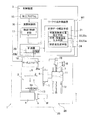
この発明の一実施形態を図1ないし図4に基づいて説明する。この実施形態では、NC工作機械がワーク寸法計測装置を備えている例について説明する。図1に示すように、NC工作機械1は、工作機械機構部2と制御装置3とを有し、主に制御装置3にワーク寸法計測装置M1が設けられている。
An embodiment of the present invention will be described with reference to FIGS. In this embodiment, an example in which an NC machine tool includes a workpiece dimension measuring device will be described. As shown in FIG. 1, the NC machine tool 1 includes a
工作機械機構部2について説明する。
工作機械機構部2はタレット式の旋盤からなり、刃物台となるタレット6が設けられている。タレット6は、この回転軸心が主軸台4の主軸5と平行となるように設けられている。タレット6は、正面形状が例えば多角形のドラム状のものであり、各周面部分からなる工具ステーションを備えている。この工具ステーションに、工具ホルダを介してバイトまたはドリル等の切削用の工具Tがそれぞれ取り付けられている。
The
The machine
タレット6は、進退台7に、主軸5の軸方向と平行に進退自在で、かつ割出回転可能に搭載されている。進退台7は、主軸5の軸方向つまりZ軸方向と直交するX軸方向に進退自在に構成されている。すなわち進退台7は、送りねじ8およびモータ9を有する進退駆動手段10により、進退駆動が行われる。このタレット6の前記Z軸方向の進退駆動は、進退台7に搭載された進退駆動手段11により行われる。進退台7のレール12および主軸台4は、共通のベッドに設置されている。
主軸5の近傍には、例えば、タッチセンサ等からなる刃先計測用のセンサ13が、センサ支持部材14を介して設置されている。センサ支持部材14は、主軸台4またはベッドに設置されている。タッチセンサ等からなるセンサ13について、接触信号が生じたときの位置検出器19の値を検出可能になっている。
The
In the vicinity of the
制御装置3について説明する。
制御装置3は、コンピュータ式の数値制御装置(NC)およびプログラマブルコントローラ(PC)で構成されたものであり、加工プログラム15を演算制御部16で解読して実行する。演算制御部16は軸送り制御手段17を有し、この軸送り制御手段17は、タレット6をX軸方向に移動させるモータ9を制御する。
サーボコントローラ18は、軸送り制御手段17に指令に応じてモータ9を制御する手段であり、モータ9に設けられたパルスコーダ等の位置検出器19の検出値でフィードバック制御を行う。
The
The
The
前記ワーク寸法計測装置M1は、計測器20と、計測データ補正手段21とを備え、この計測データ補正手段21は、材質別熱変化量設定手段22と、材質・環境温度入力手段23と、補正値生成手段24とを有する。計測データ補正手段21は、計測器20で計測された計測値を補正値または補正係数で補正して計測出力値とするものである。前記計測器20は、ワークWの所定部例えば外径の寸法を計測するものである。この計測器20は、計測器本体20aと、計測部20bとを有する。例えば、タレット6の一つの周面部分に、タッチセンサ等からなる計測器本体20aが設けられる。タレット6にある計測器本体20aがワークWの外径面に接したときの位置検出器19の値を、前記計測部20bが読み取るように構成されている。ただし、計測器20はこの構成に限定されるものではない。
The workpiece dimension measuring apparatus M1 includes a measuring
前記制御装置3は刃先計測手段を備え、この刃先計測手段は、前記刃先計測用のセンサ13と、計測部20bとを有する。この計測部20bは、タレット6の工具Tの刃先がセンサ13に接したときの位置検出器19の値を読み取るように構成されている。位置検出器19は、タレット6の位置を直接検出するものであっても良い。
The
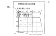
前記材質別熱変化量設定手段22には、計測器本体20aが設置される環境温度の情報と、ワークWの材質の温度による熱変化量との関係が設定されている。ワークWは、材質の種類に応じて線膨張係数が異なる。この実施形態においては、図2に示すように、線膨張係数の異なる材質、ワークWの大きさをそれぞれグループ分けしておき、複数のテストを実施することによって、任意の材質および任意のワークWの大きさにおける熱変化量を、記憶手段からなる内部情報データベース22aに予め記憶しておく。この場合において、ワークWの「大きさ」とは、軸の外径寸法、軸孔の内径寸法、および軸方向寸法の少なくともいずれか一つを含む。また、図1に示すように、このNC工作機械1のうちワークWが把持されるカバー25内部に、前記環境温度を計測可能な温度センサ26が設けられている。テスト実施時において、例えば、テスト用のワークを加工することでカバー25内部の環境温度を上昇させて、温度センサ26により正確な環境温度を計測し得る。ただし、ワークを加工しないで環境温度を図示外の熱源等を用いて上昇させて、温度センサ26により環境温度を計測しても良い。この場合、テスト用にワークWを加工する手間、材料費の低減を図ることができる。
In the material-specific heat change amount setting means 22, the relationship between the information on the environmental temperature at which the measuring instrument
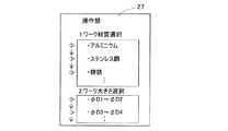
前記材質・環境温度入力手段23は、計測対象のワークWの材質等の情報および前記環境温度を入力する手段である。制御装置3の記憶手段には、加工可能な複数のワークWの材質の情報および複数のワークWの大きさの情報が記憶されている。図3に示すように、操作者は、この工作機械の操作盤27の操作により、計測対象であり加工対象である所望のワークWの材質の情報を、選択し得る。さらにこの操作盤27の操作により、所望のワークWの大きさの情報を選択し得る。
The material / environment temperature input means 23 is a means for inputting information such as the material of the workpiece W to be measured and the environment temperature. The storage means of the
例えば、操作盤27に、複数のワークWの材質の情報「アルミニウム、ステンレス鋼、鋳鉄・・・」等が出力表示され、操作者がそれらのうちの一つを選択し確定操作することにより、この一つの材質の情報が、記憶手段からなる事前入力情報データベース23a(図1)に書換え可能に記憶される。所望のワークWの大きさの情報についても、操作盤27の操作により、一つのワークWの大きさの情報、例えば「外径φ D1〜D2 」等が前記事前入力情報データベース23aに記憶される。
また、図1に示すカバー25内部に設けられる温度センサ26により計測される環境温度の情報が、前記事前入力情報データベース23aに書換え可能に記憶される。この環境温度の情報は、温度センサ26を常時監視することで得られ、環境温度が変化する毎に事前入力情報データベース23aに書換えられる。
For example, information on the materials of the plurality of workpieces W such as “aluminum, stainless steel, cast iron,...” Is output and displayed on the
Further, information on the environmental temperature measured by the
図1に示すように、前記補正値生成手段24は、材質・環境温度入力手段23で入力されたワークWの材質,大きさの情報、および環境温度の情報を、材質別熱変化量設定手段22の設定内容に照らして、補正値または補正係数を生成する。つまり、補正値生成手段24は、事前入力データベース23aに一時的に記憶された、ワークWの材質の情報、ワークWの大きさの情報および環境温度の情報を、内部情報データベース22aに記憶された、材質およびワークWの大きさにおける熱変化量に照らして、計測器20で計測された計測値を補正する補正値、または補正係数を生成する。
As shown in FIG. 1, the correction
この場合において、補正値生成手段24は、事前入力データベース23aに記憶されたワークWの材質および大きさの情報が、内部情報データベース22aにあるか否かを判断する。「あり」との判断で、補正値生成手段24は、この内部情報データベース22a内にある、環境温度の情報と、前記ワークWの材質の温度による熱変化量との関係(個別情報と称す)を個別に呼び出し、この関係は補正値等の生成に供される。補正値生成手段24は、温度変化対応量±個別情報を演算することで、補正値を生成することが可能となる。
In this case, the correction value generation means 24 determines whether or not the material information and size information of the workpiece W stored in the pre-input database 23a is in the
補正値生成手段24は、事前入力データベース23aに記憶されたワークWの材質が、内部情報データベース22aにないと判断すると、例えば、前記ワークWの材質の線膨張係数に最も近似する線膨張係数を有するワークWを、内部情報データベース22aから自動的に選択するようにしても良い。内部情報データベース22aにないワークWの大きさの情報についても、補正値生成手段24は、前記と同様に、計測対象等のワークWの大きさに最も近似するワークWの大きさの情報(近似情報と称す)を、内部情報データベース22aから自動的に選択するようにしても良い。
If the correction
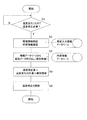
次に、計測値を補正する補正方法を、図4の流れ図と共に説明する。
このNC工作機械1の主電源をオンにする開始条件でステップS1に移行し、計測データ補正手段21は、温度センサ26による測定結果に基づいて環境温度が変化したか否か、および計測値の温度補正が必要か否かを判断する。このステップS1における判断は、前記主電源をオンにしている状態で常に行われる。ただし、ステップS1における判断を、一定時間毎または間欠的に行っても良い。予め定める閾値よりも環境温度が変化したと計測データ補正手段21が判断すると、計測値の温度補正が必要と判断され、ステップS2に移行する。環境温度が閾値内にあると計測データ補正手段21が判断すると、計測値の温度補正不要と判断され、ステップS1に戻る。
Next, a correction method for correcting the measurement value will be described with reference to the flowchart of FIG.
The process proceeds to step S1 under the start condition for turning on the main power supply of the NC machine tool 1, and the measurement data correction means 21 determines whether or not the environmental temperature has changed based on the measurement result by the
ステップS2において、計測データ補正手段21は、事前入力情報データベース23aの環境情報、ワークWの材質、大きさの情報を確認する。次に、ステップS3に移行し、計測データ補正手段21は、内部情報データベース22a内にある前記個別情報または前記近似情報を呼び出す。次に、ステップS4に移行し、補正値生成手段24は、温度変化対応量±個別情報を演算して補正量または補正係数を求め、記憶手段に記憶する。ステップS5では、この記憶された補正値または補正係数を用いて、工具Tの送り量を補正する。すなわち、前記刃先計測手段により、使用される工具Tの刃先が計測されており、この計測値に補正係数を乗じて工具Tの送り量とするか、または計測値に補正量を加えて前記送り量とする。その後このステップS1〜ステップS5の処理を繰り返す。
In step S <b> 2, the measurement
以上説明したワーク寸法計測装置M1によれば、前記補正値生成手段24により生成された補正値または補正係数を用いて、工具Tの送り量を補正し得る。したがって、ワークWの材質等によりその温度の変化量が微妙に変化する場合であっても、このワークWの材質等および環境温度に応じた微妙な変化量を見込んだ補正値を得ることができる。少量多品種のワークWを生産する場合においても、各ワークWの材質等および環境温度に応じた微妙な変化量を見込んだ補正値を得ることができるため、従来技術のものより加工精度を高めることができる。
According to the workpiece dimension measuring apparatus M1 described above, the feed amount of the tool T can be corrected using the correction value or the correction coefficient generated by the correction
前記計測データ補正手段21は、所定温度差以上の温度変化(例えば1度以上の温度変化)があったとの判断で計測器20で計測された計測値を補正するものであるため、温度補正が必要な場合にのみ、計測器20で計測された計測値を補正することができる。所定の温度変化なしとの判断では、計測データ補正手段21は温度監視状態に戻るだけで、計測値を補正しない。したがって、計測データ補正手段21の演算処理負荷を低減することができるうえ、計測値の補正を迅速に行うことができる。僅かな温度差では加工の誤差に影響しないため、温度補正すると、補正が無駄になるだけでなく、過度の補正によって、却って精度低下を招く。この実施形態では、所定温度差以上の温度変化があった場合に計測値を補正するので、このような問題が回避される。
The measurement
この実施形態のように、ワーク寸法計測装置M1を備えた工作機械である場合、ワークWの材質、大きさ、および環境温度に応じた、より正確な補正値または補正係数を生成し、この補正値等を用いて工具Tの送り量を補正し得る。ワークWの材質を設計変更したり、環境温度が種々変わり得る場合であっても、変更の都度工具Tの送り量を容易に且つ迅速に補正することができる。それ故、従来技術のものより、ワークWの加工精度を高めることができる。したがって、製品の歩留まりを高めることが可能となり、製作コストの低減を図ることが可能となる。 In the case of the machine tool including the workpiece dimension measuring device M1 as in this embodiment, a more accurate correction value or correction coefficient is generated according to the material, size, and environmental temperature of the workpiece W, and this correction is performed. The feed amount of the tool T can be corrected using a value or the like. Even when the design of the material of the workpiece W is changed or the environmental temperature can be changed variously, the feed amount of the tool T can be easily and quickly corrected each time the change is made. Therefore, the processing accuracy of the workpiece W can be increased as compared with the conventional technique. Therefore, the yield of products can be increased, and the production cost can be reduced.
次に、この発明の他の実施形態について図5、図6等と共に説明する。
以下の説明においては、前述の実施形態で説明している事項に対応している部分には同一の参照符を付し、重複する説明を略する場合がある。構成の一部のみを説明している場合、構成の他の部分は、先行して説明している形態と同様とする。実施の各形態で具体的に説明している部分の組合せばかりではなく、特に組合せに支障が生じなければ、実施の形態同士を部分的に組合せることも可能である。
Next, another embodiment of the present invention will be described with reference to FIGS.
In the following description, portions corresponding to the matters described in the above-described embodiment are denoted by the same reference numerals, and overlapping descriptions may be omitted. When only a part of the configuration is described, the other parts of the configuration are the same as those described in the preceding section. Not only the combination of the parts specifically described in each embodiment, but also the embodiments can be partially combined as long as the combination does not hinder.
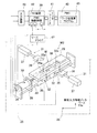
この発明の他の実施形態では、旋盤本体で加工済みのワークWの外径等の寸法を計測するワーク寸法計測装置M2に適用している。
すなわち、ワーク寸法計測装置M2は、基台28上に、ワーク載置台29、サーボモータ30、ワーク位置決め装置31、タッチセンサ32等を設けて構成されている。サーボモータ30はボールねじ33を回転させるものであり、パルスコーダ34を有している。
In another embodiment of the present invention, the present invention is applied to a workpiece dimension measuring device M2 that measures dimensions such as the outer diameter of a workpiece W that has been processed by a lathe body.
That is, the workpiece dimension measuring apparatus M2 is configured by providing a workpiece mounting table 29, a
ボールねじ33には、互いに離れた一対のセンサ取付台35,35が各々ボールナット36を介して螺合し、各センサ取付台35は、ボールねじ33と平行に配置されたガイドロッド36で案内されて、ボールねじ33の回転で進退させられる。
各センサ取付台35には、それぞれタッチセンサ32が取り付けられており、その接触子32aは、ワーク載置台29に形成されたスリット29aを介して下側からワーク載置台29の上方側に臨まされている。
A pair of
A
ワーク位置決め装置31は、エアシリンダなどからなる進退駆動源37の進退ロッドの先端にワーク当接部38を設けたものであり、ワーク載置台29上の中央位置を挟んで接触子32aの進退方向と直交する方向に互いに対向し合うように一対配置されている。
NC装置39は、プログラマブルマシンコントローラ(PMC)40と共に工作機械の全体の制御を行うものであり、両者39,40は、インタフェース(NC/PCウィンドウ)41で接続されている。NC装置39のPMC軸制御部42は、8軸の制御機能を有しており、そのうちの7軸の制御機能が旋盤本体43とガントリローダ44の各軸の制御に割当てられる。残り1軸の制御機能は、ワーク寸法計測装置M2のサーボモータ30の制御に使用される。PMC40には、その書き込みプログラムの1つとして、ワーク寸法計測装置M2のワーク載置台29上のワークWの外径を計測するためのワーク径演算プログラム45が準備されている。なお、NC装置39の加工プログラムには、加工済みワークをガントリローダ44によってワーク寸法計測装置M2に搬入するローダ制御プログラムと、ワーク寸法計測装置M2のサーボモータ30や進退駆動源37をワーク計測のために制御するプログラムとを追加しておく。
The
The
ワーク寸法計測装置M2のパルスコーダ34の出力は、NC装置39のPMC軸制御部42にフィードバックされ、タッチセンサ32の検出出力は入力装置46を介してNC装置39に入力される。NC装置39のPMC軸制御部42から出力されるワーク寸法計測装置M2用の軸駆動指令は、サーボドライバ47を介してサーボモータ30に与えられる。
The output of the
上記構成の動作を説明する。旋盤本体43で加工されたワークWは、ガントリローダ44によってワーク寸法計測装置M2のワーク載置台29上に移送される。ワーク載置台29上に載置されたワークWは、対向配置された一対のワーク位置決め装置31の進退ロッドの進出動作により、そのワーク当接部38で把持されてワーク載置台29上の中央位置に位置決めされる。
次に、タッチセンサ32がワークWと接してオンするまで、センサ取付台35がサーボモータ30の駆動によって右方向および左方向に順次移動させられる。この右行きでオンしたときの座標値と、左行きでオンしたときの座標値とが、サーボモータ30のパルスコーダ34からPMC軸制御部42にフィードバックされた検出値から各々読み取られる。これら座標値の差によってワークWの外径が演算される。
The operation of the above configuration will be described. The workpiece W processed by the
Next, until the
このワーク径が演算された後、図4の流れ図に示す処理が実行される。すなわち、NC装置39内における計測データ補正手段21(図1参照)は、温度センサ26による測定結果に基づいて環境温度が変化したか否か、および計測値の温度補正が必要か否かを判断する。予め定める閾値よりも環境温度が変化したと計測データ補正手段21が判断すると、前記ワーク径の温度補正が必要と判断され、ステップS2に移行する。以下図4と同様に、ステップS3を経てステップS4において、補正値生成手段24は、温度変化対応量±個別情報を演算して補正量または補正係数を求め、記憶手段に記憶する。ステップS5では、この記憶された補正値または補正係数を用いて、次のワークWの加工時に工具位置の補正が行われる。ただし、次のワークWは、測定対象にある現ワークWと同一材質、同一の大きさであるものとする。この実施形態によると、図1に示す実施形態と同様の作用効果を奏する。
なお、計測を終えたワークWは、ガントリローダ44によって所定のワーク搬出位置まで搬出される。計測の終了したワーク寸法計測装置M2では、ワーク位置決め装置31およびタッチセンサ32が元の待機位置まで後退する。
After the workpiece diameter is calculated, the process shown in the flowchart of FIG. 4 is executed. That is, the measurement data correction means 21 (see FIG. 1) in the
The workpiece W that has been measured is unloaded to a predetermined workpiece unloading position by the
前述の各実施形態では、NC工作機械の制御装置3等に、ワーク寸法計測装置M1が設けられている構成を示したが、この構成に限定されるものではない。例えば、このワーク寸法計測装置M1を計測アンプ等に適当しても良い。この場合、ワーク材質、ワークの大きさに応じて、ワークの所定部の寸法を、従来の計測アンプよりもより正確に且つ簡単に計測することができる。
この発明の他の実施形態として、ワークWの材質の熱変化量を内部情報データベース22aに記憶しておき、ワークWの大きさの情報については内部情報データベース22aに記憶しないようにすることも可能である。この場合、計測データ補正手段21の演算処理負荷を低減することができる。
計測器20の計測器本体20aを、タレット6の周面部分ではなく工作機械の他の場所に独立して設けても良い。
NC工作機械以外の工作機械の制御装置に、ワーク寸法計測装置M1を設けても良い。この場合において、ワークWが軸以外のものであっても良い。例えば板状のワークである場合、板の厚み、一辺の長さ等がこのワークの「大きさ」に相当する。
また、工作機械の制御装置3とは独立してワーク寸法計測装置M1を設けても良い。
In each of the above-described embodiments, the configuration in which the workpiece dimension measuring device M1 is provided in the
As another embodiment of the present invention, the heat change amount of the material of the workpiece W may be stored in the
The measuring instrument
You may provide the workpiece dimension measuring apparatus M1 in the control apparatus of machine tools other than NC machine tool. In this case, the workpiece W may be other than the shaft. For example, in the case of a plate-shaped workpiece, the thickness of the plate, the length of one side, and the like correspond to the “size” of the workpiece.
Moreover, you may provide the workpiece dimension measuring apparatus M1 independently of the
1…NC工作機械
20…計測器
21…計測データ補正手段
22…材質別熱変化量設定手段
23…材質・環境温度入力手段
24…補正値生成手段
M1,M2…ワーク寸法計測装置
W…ワーク
DESCRIPTION OF SYMBOLS 1 ...
Claims (3)
この計測データ補正手段は、前記計測器が設置される環境温度の情報と、ワークの材質の温度による熱変化量との関係を設定した材質別熱変化量設定手段と、
計測対象のワークの材質の情報および前記環境温度の情報を入力する材質・環境温度入力手段と、
この材質・環境温度入力手段で入力されたワークの材質の情報および前記環境温度の情報を、前記材質別熱変化量設定手段の設定内容に照らして前記補正値または補正係数を生成する補正値生成手段とを有する
ワーク寸法計測装置。 A measuring instrument that measures the dimensions of a predetermined part of the workpiece, and measurement data correction means that corrects a measurement value measured by the measuring instrument with a correction value or a correction coefficient to obtain a measurement output value;
The measurement data correction means includes a material-specific heat change amount setting means for setting a relationship between information on the environmental temperature where the measuring instrument is installed and the heat change amount due to the temperature of the material of the workpiece.
Material / environment temperature input means for inputting information on the material of the workpiece to be measured and information on the environmental temperature,
The correction value generation for generating the correction value or the correction coefficient based on the setting contents of the material-specific heat change amount setting means for the workpiece material information and the environmental temperature information input by the material / environment temperature input means And a workpiece dimension measuring apparatus.
Priority Applications (1)
| Application Number | Priority Date | Filing Date | Title |
|---|---|---|---|
| JP2008136348A JP2009279727A (en) | 2008-05-26 | 2008-05-26 | Workpiece dimension measuring device and machine tool |
Applications Claiming Priority (1)
| Application Number | Priority Date | Filing Date | Title |
|---|---|---|---|
| JP2008136348A JP2009279727A (en) | 2008-05-26 | 2008-05-26 | Workpiece dimension measuring device and machine tool |
Publications (1)
| Publication Number | Publication Date |
|---|---|
| JP2009279727A true JP2009279727A (en) | 2009-12-03 |
Family
ID=41450730
Family Applications (1)
| Application Number | Title | Priority Date | Filing Date |
|---|---|---|---|
| JP2008136348A Pending JP2009279727A (en) | 2008-05-26 | 2008-05-26 | Workpiece dimension measuring device and machine tool |
Country Status (1)
| Country | Link |
|---|---|
| JP (1) | JP2009279727A (en) |
Cited By (5)
| Publication number | Priority date | Publication date | Assignee | Title |
|---|---|---|---|---|
| EP3147062A1 (en) | 2015-09-28 | 2017-03-29 | Fanuc Corporation | Wire electric discharge machine |
| JP2019005836A (en) * | 2017-06-23 | 2019-01-17 | 中村留精密工業株式会社 | Correction method of thermal displacement of machine tool |
| CN110153513A (en) * | 2018-02-16 | 2019-08-23 | 发那科株式会社 | Discharging processing machine |
| JP2020059071A (en) * | 2018-10-05 | 2020-04-16 | 村田機械株式会社 | Machine tools and processing methods |
| US12055911B2 (en) | 2019-04-01 | 2024-08-06 | Trumpf Werkzeugmaschinen Gmbh + Co. Kg | Method for offset measure compensation |
Citations (4)
| Publication number | Priority date | Publication date | Assignee | Title |
|---|---|---|---|---|
| JPH04343642A (en) * | 1991-05-16 | 1992-11-30 | Niigata Eng Co Ltd | Work thermal expansion correcting method for cut machining |
| JPH0775937A (en) * | 1993-09-07 | 1995-03-20 | Sodick Co Ltd | Machine tool and control method thereof |
| JP2001239438A (en) * | 2000-02-28 | 2001-09-04 | Enshu Ltd | Method of correcting thermal displacement of machine tool, device therefor, storage medium, and method of processing in machine tool |
| JP2006212765A (en) * | 2005-02-07 | 2006-08-17 | Enshu Ltd | Machine tool thermal displacement compensation method |
-
2008
- 2008-05-26 JP JP2008136348A patent/JP2009279727A/en active Pending
Patent Citations (4)
| Publication number | Priority date | Publication date | Assignee | Title |
|---|---|---|---|---|
| JPH04343642A (en) * | 1991-05-16 | 1992-11-30 | Niigata Eng Co Ltd | Work thermal expansion correcting method for cut machining |
| JPH0775937A (en) * | 1993-09-07 | 1995-03-20 | Sodick Co Ltd | Machine tool and control method thereof |
| JP2001239438A (en) * | 2000-02-28 | 2001-09-04 | Enshu Ltd | Method of correcting thermal displacement of machine tool, device therefor, storage medium, and method of processing in machine tool |
| JP2006212765A (en) * | 2005-02-07 | 2006-08-17 | Enshu Ltd | Machine tool thermal displacement compensation method |
Cited By (10)
| Publication number | Priority date | Publication date | Assignee | Title |
|---|---|---|---|---|
| EP3147062A1 (en) | 2015-09-28 | 2017-03-29 | Fanuc Corporation | Wire electric discharge machine |
| CN106552973A (en) * | 2015-09-28 | 2017-04-05 | 发那科株式会社 | Wire electric discharge machine |
| KR101892355B1 (en) | 2015-09-28 | 2018-09-28 | 화낙 코퍼레이션 | Wire electric discharge machine |
| US10786857B2 (en) | 2015-09-28 | 2020-09-29 | Fanuc Corporation | Wire electric discharge machine |
| JP2019005836A (en) * | 2017-06-23 | 2019-01-17 | 中村留精密工業株式会社 | Correction method of thermal displacement of machine tool |
| CN110153513A (en) * | 2018-02-16 | 2019-08-23 | 发那科株式会社 | Discharging processing machine |
| US10960478B2 (en) | 2018-02-16 | 2021-03-30 | Fanuc Corporation | Electric discharge machine |
| CN110153513B (en) * | 2018-02-16 | 2021-04-13 | 发那科株式会社 | Electric discharge machine |
| JP2020059071A (en) * | 2018-10-05 | 2020-04-16 | 村田機械株式会社 | Machine tools and processing methods |
| US12055911B2 (en) | 2019-04-01 | 2024-08-06 | Trumpf Werkzeugmaschinen Gmbh + Co. Kg | Method for offset measure compensation |
Similar Documents
| Publication | Publication Date | Title |
|---|---|---|
| US9945799B2 (en) | Thermal displacement correction device for machine tool | |
| KR102123173B1 (en) | Automatic conversion device for thermal displacement compensation parameters and conversion method for machine tools | |
| JPWO2002032620A1 (en) | Measuring method and apparatus, and machine tool and work processing method having the apparatus | |
| JP7337664B2 (en) | Correction value measurement method and correction value measurement system for position measurement sensor in machine tool | |
| JP2015196239A (en) | Wire discharge machine having thermal displacement function of upper and lower guide | |
| JP2009279727A (en) | Workpiece dimension measuring device and machine tool | |
| JP2021104564A (en) | Thermal displacement correction device | |
| JPH1158179A (en) | Heat displacement correcting method of machine tool and device therefor | |
| JP2020116666A (en) | Tool management system of machine tool | |
| JP2002144191A (en) | Machine tool | |
| JP2013255982A (en) | Machine tool, and correction method of thermal deformation thereof | |
| KR20150041328A (en) | Automatic conversion device of themal deformation compensation parameter automatic conversion for machine tool and method thereof | |
| JP4082598B2 (en) | Method and apparatus for correcting thermal displacement of numerically controlled machine tool | |
| JP2005034934A (en) | Numerically controlled apparatus, machine tool equipped with the same, and method for calculating coordinate of workpiece | |
| JP6168396B2 (en) | Machine Tools | |
| US10955238B1 (en) | In-process automatic recalibration | |
| JP2002273642A (en) | Ball screw feed drive correcting method, and ball screw feed drive device | |
| JP2019166604A (en) | Cutting device and control method for the same | |
| JP5846400B2 (en) | Machine tool and its thermal deformation correction method | |
| JP2008049407A (en) | Method and apparatus for machining crankshaft, control system, and control program | |
| JPS592045B2 (en) | Temperature compensation method and device for positioning in numerically controlled machines | |
| JP2004034187A (en) | Machine tool | |
| JP2002224935A (en) | Sizing device for machine tool and recording medium readable with computer, which is recorded with control program for the device is recorded | |
| JP2006116654A (en) | Thermal deformation correction method and thermal deformation correcting device of nc machine tool | |
| JP2021094627A (en) | Thermal displacement correction method for machine tool |
Legal Events
| Date | Code | Title | Description |
|---|---|---|---|
| A621 | Written request for application examination |
Effective date: 20110216 Free format text: JAPANESE INTERMEDIATE CODE: A621 |
|
| A131 | Notification of reasons for refusal |
Free format text: JAPANESE INTERMEDIATE CODE: A131 Effective date: 20120710 |
|
| A02 | Decision of refusal |
Effective date: 20121106 Free format text: JAPANESE INTERMEDIATE CODE: A02 |