JP2009281152A - High place mounting electric fan - Google Patents
High place mounting electric fan Download PDFInfo
- Publication number
- JP2009281152A JP2009281152A JP2008131053A JP2008131053A JP2009281152A JP 2009281152 A JP2009281152 A JP 2009281152A JP 2008131053 A JP2008131053 A JP 2008131053A JP 2008131053 A JP2008131053 A JP 2008131053A JP 2009281152 A JP2009281152 A JP 2009281152A
- Authority
- JP
- Japan
- Prior art keywords
- drawstring
- fan
- high place
- switch
- stand
- Prior art date
- Legal status (The legal status is an assumption and is not a legal conclusion. Google has not performed a legal analysis and makes no representation as to the accuracy of the status listed.)
- Granted
Links
Images


Landscapes
- Structures Of Non-Positive Displacement Pumps (AREA)
Abstract
【課題】引き紐のツマミ高さを容易に調整することができる高所取付用扇風機を得ること。
【解決手段】建物の高所に取付けられるスタンド1と、前記スタンド1に支持され送風ファン8及びモータ13を備える扇風機本体21と、前記スタンド1に設置され前記モータ13の電気回路の接点を切換えて該モータ13の運転、停止及び風量切換を行うスイッチと、前記スイッチを操作する引き紐と、前記引き紐の中間部に接続された引き紐長さ調節装置4と、を備える。
【選択図】 図1An object of the present invention is to provide a fan for mounting at a high place, which can easily adjust the height of a knob of a drawstring.
SOLUTION: A stand 1 attached to a high place of a building, a fan main body 21 provided with a blower fan 8 and a motor 13 supported by the stand 1, and a contact point of an electric circuit of the motor 13 installed on the stand 1 are switched. A switch for operating, stopping and switching the air volume of the motor 13, a drawstring for operating the switch, and a drawstring length adjusting device 4 connected to an intermediate portion of the drawstring.
[Selection] Figure 1
Description
本発明は、天井や壁等に取付けられる高所取付用扇風機に関するものである。 The present invention relates to a fan for mounting at a high place, which is mounted on a ceiling or a wall.
一般に、高所取付用扇風機は、壁等に取付けられる別体のコントローラーにより、個別又は複数同時に制御されている。これとは別に、扇風機本体に風量を切換えるプルスイッチを設置し、その操作レバーに接続された引き紐を引くことにより、スイッチの接点が次々と切換わり、風量切換えや電源の入、切がなされる高所取付用扇風機がある。近年、省エネの観点から、こまめに個別に入、切りができるこのような形態の扇風機が見直されている。 Generally, a fan for mounting at a high place is controlled individually or simultaneously by a separate controller attached to a wall or the like. Separately from this, by installing a pull switch that switches the air volume in the fan body and pulling the pull string connected to the operation lever, the switch contacts are switched one after another, and the air volume is switched and the power is turned on and off. There is a fan for mounting at high places. In recent years, such an electric fan that can be frequently turned on and off individually has been reviewed from the viewpoint of energy saving.
このような形態の高所取付用扇風機として、従来、室内側と室外側を開口した枠状で室外側に開閉シャッターを設け、内部に羽根を固着したモータを設けた扇風機本体と、この扇風機本体に設けられ前記モータの電気回路を開閉するスイッチ部と、このスイッチ部を操作する操作部とを備え、前記スイッチ部と操作部とからなる運転・停止手段を構成し、前記運転・停止の操作部を、前記スイッチの取り付け位置を変えることなく、前記換気扇本体の室内側の左右どちら側でも操作できる構成とした換気扇がある(例えば、特許文献1参照)。 Conventionally, as a fan for mounting at high places in this form, a fan main body provided with a motor in which an open / close shutter is provided on the outdoor side in a frame shape that opens the indoor side and the outdoor side, and a blade is fixed inside, and the electric fan main body A switch part that opens and closes the electric circuit of the motor, and an operation part that operates the switch part, and constitutes an operation / stop unit comprising the switch part and the operation part. There is a ventilation fan in which the unit can be operated on either the left or right side of the indoor side of the ventilation fan body without changing the mounting position of the switch (see, for example, Patent Document 1).
高所取付用扇風機は、設置される建物の天井高さによって引き紐のツマミ高さが変わってしまう。使い勝手を良くするために、引き紐の長さを調節してツマミ高さを調整する必要があるが、従来の高所取付用扇風機は、引き紐が直接切換スイッチに接続されているため、ツマミ高さを調整するためには、紐を適当な長さのものに交換するか、紐の中間で結びを作り長さを調節するしかない。そのため、コスト、手間、見栄えの悪化等の問題があった。また、冬場等のオフシーズンには、引き紐が邪魔にならないように、紐を天井付近で束ねなければならない、という問題があった。 As for the fan for mounting at a high place, the knob height of the drawstring changes depending on the ceiling height of the building to be installed. In order to improve usability, it is necessary to adjust the height of the knob by adjusting the length of the pull string. However, in conventional fans for mounting at high places, the pull string is directly connected to the selector switch. The only way to adjust the height is to replace the string with an appropriate length, or adjust the length by making a knot in the middle of the string. For this reason, there are problems such as cost, labor and deterioration of appearance. Further, in the off season such as in winter, there is a problem that the string must be bundled near the ceiling so that the drawstring does not get in the way.
本発明は、上記に鑑みてなされたものであって、オールシーズンに亘り、引き紐のツマミ高さを容易に調整することができる高所取付用扇風機を得ることを目的とする。 This invention is made | formed in view of the above, Comprising: It aims at obtaining the fan for high place attachment which can adjust the knob height of a drawstring easily over all seasons.
上述した課題を解決し、目的を達成するために、本発明は、建物の高所に取付けられるスタンドと、前記スタンドに支持され送風ファン及びモータを備える扇風機本体と、前記スタンドに設置され前記モータの電気回路の接点を切換えて該モータの運転、停止及び風量切換を行うスイッチと、前記スイッチを操作する引き紐と、前記引き紐の中間部に接続された引き紐長さ調節装置と、を備えることを特徴とする。 In order to solve the above-described problems and achieve the object, the present invention provides a stand attached to a high place of a building, a fan body supported by the stand and provided with a blower fan and a motor, and the motor installed in the stand. A switch for switching the contact of the electric circuit to operate, stop and switch the air flow, a pull string for operating the switch, and a pull string adjusting device connected to an intermediate portion of the pull string It is characterized by providing.
この発明によれば、引き紐を交換したり、切断したり、中間で結んだりすることなく、引き紐のツマミ高さを容易に調整することが可能であり、天井高さにかかわらず、ツマミ高さを、ユーザーの身丈に合う高さに調整することができる。また、オフシーズンには、天井付近まで引き紐を巻上げることができ、引き紐が邪魔になることはなく、見栄えも良い、という効果を奏する。 According to the present invention, it is possible to easily adjust the knob height of the pull string without exchanging, cutting, or tying the pull string, and the knob regardless of the ceiling height. The height can be adjusted to suit the user's height. In the off-season, the drawstring can be wound up to the vicinity of the ceiling, and the drawstring does not get in the way and the appearance is good.
以下に、本発明にかかる高所取付用扇風機の実施の形態を図面に基づいて詳細に説明する。なお、この実施の形態によりこの発明が限定されるものではない。 Embodiments of a fan for mounting at high places according to the present invention will be described below in detail with reference to the drawings. Note that the present invention is not limited to the embodiments.
実施の形態
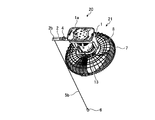
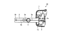
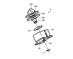
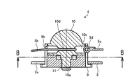
図1は、本発明にかかる高所取付用扇風機の実施の形態を示す全体斜視図であり、図2は、実施の形態の高所取付用扇風機のアーム部を示す上面図であり、図3は、実施の形態の引き紐長さ調節装置を示す上方分解斜視図であり、図4は、実施の形態の引き紐長さ調節装置を示す下方分解斜視図であり、図5は、実施の形態の引き紐長さ調節装置を示す縦断面図であり、図6は、図5のB−B線に沿う断面図である。
Embodiment FIG. 1 is an overall perspective view showing an embodiment of a high place mounting fan according to the present invention, and FIG. 2 is a top view showing an arm portion of the high place mounting fan according to the embodiment. 3 is an exploded top perspective view showing the pull string adjusting device of the embodiment, FIG. 4 is a bottom exploded perspective view showing the pull string length adjusting device of the embodiment, and FIG. FIG. 6 is a longitudinal sectional view showing the drawstring length adjusting device of the embodiment, and FIG. 6 is a sectional view taken along line BB in FIG.
図1及び図2に示すように、実施の形態の高所取付用扇風機20は、建物の高所としての天井に取付けられるスタンド1と、スタンド1に支持され送風ファン8、モータ13及びファンガード7を備える扇風機本体21と、スタンド1に設置されモータ13の電気回路の接点を切換えてモータ13の運転、停止及び風量切換を行うプルスイッチ3と、プルスイッチ3を操作する引き紐5a、5bと、引き紐5aと引き紐5bの間に接続された引き紐長さ調節装置4と、を備えている。
As shown in FIG. 1 and FIG. 2, the high
扇風機本体21を2本の支柱により下向きに旋回可能に支持するスタンド1のベース部1aには、引き紐5bを送風ファン8やファンガード7に干渉しないように送風ファン8の側方に垂らすためのアーム2が、その先端部が水平方向に突出するように取付けられている。
The
プルスイッチ3は、スタンド1のベース部1aのアーム2基端部近傍に設置されている。プルスイッチ3は、操作レバー3aを備え、操作レバー3aには引き紐5aが接続されている。引き紐5aを引くと、モータ13の電気回路の接点が切換えられてモータ13の運転、停止及び風量切換が行われる。
The pull switch 3 is installed in the vicinity of the base end portion of the
プルスイッチ3の操作レバー3aとアーム2上に配置した引き紐長さ調整装置4とは、引き紐5aにより接続され、引き紐長さ調整装置4とツマミ6の間は、引き紐5bにより接続されている。引き紐5bは、アーム2の先端部の円孔2bから下方へ垂れ下がり、その先端にツマミ6が接続されている。
The pulling
図3〜図6に示すように、引き紐長さ調整装置4は、概ね、円筒状に形成されたスライドベース9と、スライドベース9内に回動自在に嵌合されるノブ10と、により構成されている。
As shown in FIG. 3 to FIG. 6, the drawstring
ノブ10は、頭部に設けられた取っ手10eと、取っ手10eの下側に環状溝として形成された引き紐巻取り部10cと、引き紐巻取り部10cに設けられた引き紐接続孔10dと、引き紐巻取り部10cの下側に設けられた四角形の固定ガイド10bと、固定ガイド10bの下方へ延びるシャフト10aと、を有している。
The
スライドベース9は、下部中央に設けられノブ10のシャフト10aが嵌合される円孔9aと、円筒壁側面に設けられた引き紐貫通孔9bと、アーム2の中間部に設けられた長孔2aに嵌合するスライド溝9cと、円筒壁側面の引き紐貫通孔9bと対向する部位に設けられた引き紐接続部9dと、を有している。
The
ノブ10は、シャフト10aをスライドベース9の円孔9aに嵌合し、Cリング11により抜け止めされて、スライドベース9に保持される。図6に示すように、四角形の固定ガイド10bが、スライドベース9に嵌め込まれた2枚の板ばね12の間に挟持され、ノブ10は、90°ずつ段階的に回転する毎に板ばね12により回り止めされるようになっている。固定ガイド10bを四角形より角数が多い多角形とすれば、90°より小さい回転角毎に、ノブ10を段階的に回り止めすることができる。
The
引き紐5bの基端は、スライドベース9の引き紐貫通孔9bを通してノブ10の引き紐接続孔10dに固定されている。取手10eを手で回してノブ10を回転させれば、引き紐5bを引き紐巻取り部10cに巻き取ることができる。引き紐巻取り部10cは、ツマミ6がアーム2の先端部に当たるまで、引き紐5bを巻上げることができる。
The base end of the
プルスイッチ3を操作するために、引き紐5bを引っ張ったとき、スライドベース9がアーム2上を摺動するように、スライドベース9のスライド溝9cが、アーム2の長孔2aに嵌合されている。長孔2aの長さは、プルスイッチ3の操作レバー3aのストロークより長くなっている。
The
引き紐5aが、操作レバー3aとスライドベース9の引き紐接続部9dとを接続していて、引き紐5bを引っ張ると、引き紐長さ調整装置4は、長孔2aにガイドされてアーム2上を摺動し、操作レバー3aを操作することができる。
When the
2枚の板ばね12によるノブ10のブレーキ力は、プルスイッチ3の操作力より大きいことは勿論、ユーザーの引張り操作力より大きく設定されていて、巻取られた引き紐5bが、ユーザーの引っ張り操作により解けてしまうことはない。
The braking force of the
以上のように、本発明にかかる高所取付用扇風機は、一般家庭用、天井取付用、壁取付用及び換気扇に有用である。 As described above, the high-place installation fan according to the present invention is useful for general household use, ceiling installation, wall installation, and ventilation fan.
1 スタンド
1a ベース部
2 アーム
2a 長孔
2b 円孔
3 プルスイッチ
3a 操作レバー
4 引き紐長さ調節装置
5a,5b 引き紐
6 ツマミ
7 ファンガード
8 送風ファン
9 スライドベース
9a 円孔
9b 引き紐貫通孔
9c スライド溝
9d 引き紐接続部
10 ノブ
10a シャフト
10b 固定ガイド
10c 引き紐巻取り部
10d 引き紐接続孔
10e 取っ手
11 Cリング
12 板ばね
13 モータ
20 高所取付用扇風機
21 扇風機本体
DESCRIPTION OF SYMBOLS 1
Claims (4)
前記スタンドに支持され送風ファン及びモータを備える扇風機本体と、
前記スタンドに設置され前記モータの電気回路の接点を切換えて該モータの運転、停止及び風量切換を行うスイッチと、
前記スイッチを操作する引き紐と、
前記引き紐の中間部に接続された引き紐長さ調節装置と、
を備えることを特徴とする高所取付用扇風機。 A stand that can be mounted at the height of a building,
An electric fan body supported by the stand and provided with a blower fan and a motor;
A switch that is installed in the stand to switch the contact point of the electric circuit of the motor to switch the operation, stop, and air volume of the motor;
A drawstring for operating the switch;
A drawstring length adjusting device connected to an intermediate portion of the drawstring;
A fan for mounting at a high place, characterized by comprising:
Priority Applications (1)
| Application Number | Priority Date | Filing Date | Title |
|---|---|---|---|
| JP2008131053A JP5295634B2 (en) | 2008-05-19 | 2008-05-19 | Fan for mounting at high places |
Applications Claiming Priority (1)
| Application Number | Priority Date | Filing Date | Title |
|---|---|---|---|
| JP2008131053A JP5295634B2 (en) | 2008-05-19 | 2008-05-19 | Fan for mounting at high places |
Publications (2)
| Publication Number | Publication Date |
|---|---|
| JP2009281152A true JP2009281152A (en) | 2009-12-03 |
| JP5295634B2 JP5295634B2 (en) | 2013-09-18 |
Family
ID=41451877
Family Applications (1)
| Application Number | Title | Priority Date | Filing Date |
|---|---|---|---|
| JP2008131053A Expired - Fee Related JP5295634B2 (en) | 2008-05-19 | 2008-05-19 | Fan for mounting at high places |
Country Status (1)
| Country | Link |
|---|---|
| JP (1) | JP5295634B2 (en) |
Citations (10)
| Publication number | Priority date | Publication date | Assignee | Title |
|---|---|---|---|---|
| JPS435478Y1 (en) * | 1966-06-15 | 1968-03-09 | ||
| JPS49134982U (en) * | 1973-03-15 | 1974-11-20 | ||
| JPS5525966A (en) * | 1978-08-15 | 1980-02-25 | Matsushita Electric Works Ltd | Sealing with cord adjsuter |
| JPH01127140U (en) * | 1988-02-24 | 1989-08-30 | ||
| JPH06223612A (en) * | 1993-01-29 | 1994-08-12 | Toshiba Lighting & Technol Corp | Luminaire |
| JPH06267326A (en) * | 1993-03-09 | 1994-09-22 | Toshiba Lighting & Technol Corp | Case, switch unit and lighting equipment |
| JP2003281927A (en) * | 2002-03-25 | 2003-10-03 | Matsushita Electric Works Ltd | lighting equipment |
| JP2005302306A (en) * | 2004-04-06 | 2005-10-27 | Makoto Nakamoto | Switching device of lighting system |
| JP2005346959A (en) * | 2004-05-31 | 2005-12-15 | Odelic Co Ltd | Lighting device |
| JP2008027793A (en) * | 2006-07-24 | 2008-02-07 | Matsushita Electric Works Ltd | Joint parts |
-
2008
- 2008-05-19 JP JP2008131053A patent/JP5295634B2/en not_active Expired - Fee Related
Patent Citations (10)
| Publication number | Priority date | Publication date | Assignee | Title |
|---|---|---|---|---|
| JPS435478Y1 (en) * | 1966-06-15 | 1968-03-09 | ||
| JPS49134982U (en) * | 1973-03-15 | 1974-11-20 | ||
| JPS5525966A (en) * | 1978-08-15 | 1980-02-25 | Matsushita Electric Works Ltd | Sealing with cord adjsuter |
| JPH01127140U (en) * | 1988-02-24 | 1989-08-30 | ||
| JPH06223612A (en) * | 1993-01-29 | 1994-08-12 | Toshiba Lighting & Technol Corp | Luminaire |
| JPH06267326A (en) * | 1993-03-09 | 1994-09-22 | Toshiba Lighting & Technol Corp | Case, switch unit and lighting equipment |
| JP2003281927A (en) * | 2002-03-25 | 2003-10-03 | Matsushita Electric Works Ltd | lighting equipment |
| JP2005302306A (en) * | 2004-04-06 | 2005-10-27 | Makoto Nakamoto | Switching device of lighting system |
| JP2005346959A (en) * | 2004-05-31 | 2005-12-15 | Odelic Co Ltd | Lighting device |
| JP2008027793A (en) * | 2006-07-24 | 2008-02-07 | Matsushita Electric Works Ltd | Joint parts |
Also Published As
| Publication number | Publication date |
|---|---|
| JP5295634B2 (en) | 2013-09-18 |
Similar Documents
| Publication | Publication Date | Title |
|---|---|---|
| CN108731105B (en) | Air conditioner and control method thereof | |
| US8186941B2 (en) | Swing structure for a ceiling fan | |
| US11959658B2 (en) | Control method for air conditioner indoor unit | |
| US20130082115A1 (en) | Remote Controlled Vent Register | |
| CN110821868B (en) | An intelligent fan with folding function | |
| KR20180019376A (en) | Ceiling type air conditioner | |
| WO2006006623A1 (en) | Indoor unit for air conditioner | |
| JP3136859U (en) | Fan | |
| JP5295634B2 (en) | Fan for mounting at high places | |
| CN205174744U (en) | An air-conditioning sweeping device and air-conditioning equipment | |
| CN113187748B (en) | A ceiling fan with adjustable lifting structure | |
| CA2806033C (en) | Oscillating fan with built-in pull-type control switch | |
| KR101263120B1 (en) | Fan for reciprocating rotation angle control apparatus | |
| CN211082351U (en) | Smart fan with folding function | |
| CN102734889B (en) | Air interchanger | |
| CN111411493B (en) | Heating device | |
| JP2010032062A (en) | Ceiling-embedded air conditioner | |
| CN203453096U (en) | Multi-head DC brushless electric fan | |
| JP5059917B2 (en) | Air supply damper device | |
| JP4580954B2 (en) | Ventilated building structure | |
| JP3103260U (en) | Ventilation system for window mounting with exhaust fan and air supply fan | |
| CN201165995Y (en) | Wind direction adjustable top fan controlled by synchronous motor | |
| CN110469908B (en) | Air conditioner | |
| CN205243907U (en) | Can realize all -round fan that turns to | |
| CN212155239U (en) | Fan head with pitching function and intelligent fan |
Legal Events
| Date | Code | Title | Description |
|---|---|---|---|
| A621 | Written request for application examination |
Free format text: JAPANESE INTERMEDIATE CODE: A621 Effective date: 20100726 |
|
| A977 | Report on retrieval |
Free format text: JAPANESE INTERMEDIATE CODE: A971007 Effective date: 20120131 |
|
| A131 | Notification of reasons for refusal |
Free format text: JAPANESE INTERMEDIATE CODE: A131 Effective date: 20120703 |
|
| A02 | Decision of refusal |
Free format text: JAPANESE INTERMEDIATE CODE: A02 Effective date: 20130226 |
|
| A521 | Request for written amendment filed |
Free format text: JAPANESE INTERMEDIATE CODE: A523 Effective date: 20130508 |
|
| A911 | Transfer to examiner for re-examination before appeal (zenchi) |
Free format text: JAPANESE INTERMEDIATE CODE: A911 Effective date: 20130521 |
|
| TRDD | Decision of grant or rejection written | ||
| A01 | Written decision to grant a patent or to grant a registration (utility model) |
Free format text: JAPANESE INTERMEDIATE CODE: A01 Effective date: 20130611 |
|
| A61 | First payment of annual fees (during grant procedure) |
Free format text: JAPANESE INTERMEDIATE CODE: A61 Effective date: 20130612 |
|
| R150 | Certificate of patent or registration of utility model |
Ref document number: 5295634 Country of ref document: JP Free format text: JAPANESE INTERMEDIATE CODE: R150 Free format text: JAPANESE INTERMEDIATE CODE: R150 |
|
| R250 | Receipt of annual fees |
Free format text: JAPANESE INTERMEDIATE CODE: R250 |
|
| R250 | Receipt of annual fees |
Free format text: JAPANESE INTERMEDIATE CODE: R250 |
|
| R250 | Receipt of annual fees |
Free format text: JAPANESE INTERMEDIATE CODE: R250 |
|
| R250 | Receipt of annual fees |
Free format text: JAPANESE INTERMEDIATE CODE: R250 |
|
| R250 | Receipt of annual fees |
Free format text: JAPANESE INTERMEDIATE CODE: R250 |
|
| R250 | Receipt of annual fees |
Free format text: JAPANESE INTERMEDIATE CODE: R250 |
|
| R250 | Receipt of annual fees |
Free format text: JAPANESE INTERMEDIATE CODE: R250 |
|
| R250 | Receipt of annual fees |
Free format text: JAPANESE INTERMEDIATE CODE: R250 |
|
| LAPS | Cancellation because of no payment of annual fees |