JP2009282917A - Interserver communication mechanism and computer system - Google Patents
Interserver communication mechanism and computer system Download PDFInfo
- Publication number
- JP2009282917A JP2009282917A JP2008136943A JP2008136943A JP2009282917A JP 2009282917 A JP2009282917 A JP 2009282917A JP 2008136943 A JP2008136943 A JP 2008136943A JP 2008136943 A JP2008136943 A JP 2008136943A JP 2009282917 A JP2009282917 A JP 2009282917A
- Authority
- JP
- Japan
- Prior art keywords
- server
- communication mechanism
- inter
- switch
- physical
- Prior art date
- Legal status (The legal status is an assumption and is not a legal conclusion. Google has not performed a legal analysis and makes no representation as to the accuracy of the status listed.)
- Withdrawn
Links
Images


Classifications
-
- H—ELECTRICITY
- H04—ELECTRIC COMMUNICATION TECHNIQUE
- H04L—TRANSMISSION OF DIGITAL INFORMATION, e.g. TELEGRAPHIC COMMUNICATION
- H04L67/00—Network arrangements or protocols for supporting network services or applications
- H04L67/01—Protocols
- H04L67/06—Protocols specially adapted for file transfer, e.g. file transfer protocol [FTP]
Landscapes
- Engineering & Computer Science (AREA)
- Computer Networks & Wireless Communication (AREA)
- Signal Processing (AREA)
- Multi Processors (AREA)
Abstract
【課題】物理サーバ毎にサーバ間通信を行うための外付けのI/Oデバイスを用意する必要がなく、プロトコル変換によるオーバヘッドも生じることのないようにする。
【解決手段】サーバ間通信機構161には、I/Oリンク201、図示しないI/Oスイッチを介して複数の物理サーバに接続されている。サーバ間通信機構161は、各物理サーバのデータをアクセスするための命令を発行する読み出し命令生成部203、読み出したデータを他のサーバに送信する書き込み命令生成部204を有し、サーバ間通信機構161の内部でデータの送信元からデータを読み出し、読み出したデータをそのままデータの送信先に書き出して、サーバ間通信機構161でデータを直接折り返すことにより物理サーバ相互間でのデータ転送を行う。
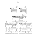
【選択図】図1There is no need to prepare an external I / O device for performing communication between servers for each physical server, and overhead caused by protocol conversion does not occur.
An inter-server communication mechanism 161 is connected to a plurality of physical servers via an I / O link 201 and an I / O switch (not shown). The inter-server communication mechanism 161 includes a read command generation unit 203 that issues a command for accessing data of each physical server, and a write command generation unit 204 that transmits the read data to another server. Data is read from the data transmission source inside the 161, the read data is written out as it is to the data transmission destination, and the data is transferred back between the physical servers by directly returning the data by the inter-server communication mechanism 161.
[Selection] Figure 1
Description
本発明は、サーバ間通信機構及びコンピュータシステムに係り、特に、2台以上の物理サーバがI/Oスイッチを介して接続されて構成されたコンピュータシステムにおける物理サーバ間の通信を行うためのサーバ間通信機構及びコンピュータシステムに関する。 The present invention relates to an inter-server communication mechanism and a computer system, and in particular, between servers for performing communication between physical servers in a computer system configured by connecting two or more physical servers via an I / O switch. The present invention relates to a communication mechanism and a computer system.
近年のコンピュータシステムは、CPU単体の高性能化及びCPUのマルチコア化等のCPUの処理性能の向上に伴って、1台の物理サーバとしてのコンピュータ上に複数の仮想サーバを稼働させるサーバ統合のニーズが高まってきている。このようなサーバ統合を行うことにより、1台の物理サーバで稼働するOSやアプリケーションの数を増大させることが可能になり、コンピュータシステムの高性能化を図ることができる。その結果、そのようなコンピュータシステムは、1台の物理サーバとしてのコンピュータに接続しなければならないI/Oデバイスの数が増加していくことが予測される。そして、より多くのI/Oデバイスを搭載するために、この種のコンピュータシステムは、サーバとI/Oデバイスとの間をPCI−Express(R)スイッチ等のI/Oスイッチを介して接続して構成する必要性が高まっている。 Recent computer systems have a need for server integration in which a plurality of virtual servers are operated on a computer as a single physical server in accordance with improvement in CPU processing performance such as high performance of a single CPU and multi-core CPU. Is growing. By performing such server integration, it is possible to increase the number of OSs and applications running on one physical server, and to improve the performance of the computer system. As a result, such a computer system is expected to increase in the number of I / O devices that must be connected to a computer as one physical server. In order to mount more I / O devices, this type of computer system connects a server and an I / O device via an I / O switch such as a PCI-Express (R) switch. The need to configure is increasing.
前述したようなI/Oスイッチを用いてサーバに接続する物理的なI/Oデバイスの数を増加させるというアプローチの一方で、物理サーバ相互間あるいは仮想サーバ相互間でI/Oデバイスを共有するI/O仮想化の普及も予測される。I/O仮想化とは、物理的なI/Oデバイスの上に複数の仮想I/Oデバイスを構築し、各物理サーバあるいは各仮想サーバのそれぞれに仮想I/Oデバイスを割り当てることにより、I/Oデバイスを物理サーバ相互間あるいは仮想サーバ相互間で共有するという方法である。 While the approach of increasing the number of physical I / O devices connected to the server using the I / O switch as described above, the I / O devices are shared between physical servers or between virtual servers. The spread of I / O virtualization is also expected. I / O virtualization is the construction of multiple virtual I / O devices on top of physical I / O devices and assigning virtual I / O devices to each physical server or each virtual server. This is a method of sharing / O devices between physical servers or between virtual servers.
I/Oデバイスを複数の物理サーバで共有する場合、そのコンピュータシステムは、複数のアップストリームポートと複数のダウンストリームポートとを有するI/Oスイッチを用意し、このI/Oスイッチのアップストリームポートのそれぞれに物理サーバを接続し、ダウンストリームポートにI/Oデバイスを接続する構成とされる。これにより、I/Oデバイスを複数の物理サーバ相互間で共有することができる。このようなI/O仮想化を用いることにより、I/Oデバイスの物理的な数を増やすことなく、統合されたサーバ上で稼働するOSやアプリケーションのそれぞれから多くのI/Oデバイスを使用することが可能になる。 When an I / O device is shared by a plurality of physical servers, the computer system prepares an I / O switch having a plurality of upstream ports and a plurality of downstream ports, and the upstream port of this I / O switch The physical server is connected to each of these, and the I / O device is connected to the downstream port. Thereby, an I / O device can be shared among a plurality of physical servers. By using such I / O virtualization, a large number of I / O devices are used from each of the OS and applications running on the integrated server without increasing the physical number of I / O devices. It becomes possible.
また、サーバ統合を行って1台の物理サーバ上に複数の仮想サーバを稼働させるようにしたコンピュータシステムは、ある物理サーバ上で稼働する仮想サーバを、稼働中に別の物理サーバに集約したり再構成したりしたいという要求がある。仮想サーバをある物理サーバから別の物理サーバに移動させるためには、その仮想サーバが使用しているメモリの内容や稼働状態を、そのまま別の物理サーバに引き継ぐということを意味する。すなわち、仮想サーバをある物理サーバから別の物理サーバに移動させるためには、このような稼働に関するメモリ上の大量のデータを高速に転送することが必要となり、物理サーバ間での高速な通信手段が必要となる。 In addition, a computer system in which a plurality of virtual servers are operated on one physical server by performing server integration, a virtual server operating on one physical server may be aggregated into another physical server during operation. There is a request to reconfigure. In order to move a virtual server from one physical server to another physical server, it means that the contents and operating state of the memory used by the virtual server are directly transferred to another physical server. In other words, in order to move a virtual server from one physical server to another, it is necessary to transfer a large amount of data on the memory related to such operation at high speed, and high-speed communication means between physical servers Is required.
コンピュータ相互間での高速な通信を行うことを可能とした通信手段に関する従来技術として、例えば、特許文献1等に記載された技術が知られている。この従来技術は、マルチノードコンピュータシステムにおいて、ノード間通信に汎用I/Oインタフェースを用い、各ノードに存在する通信制御装置がデータ転送のための転送コマンドを解釈して、汎用I/Oインタフェースの制御を行ってノード間のデータ転送を高速に行うことを可能にするというものである。
前述した従来技術は、物理サーバ相互間の通信に適用した場合、各物理サーバにサーバ間通信用のI/Oデバイスを接続し、各物理サーバの通信用I/Oデバイス相互間で通信を行うことになり、これにより、サーバ間での高速通信を実現することが可能になる。このような手法を用いて、複数の物理サーバの全てがその相互間で通信を行うためには、各物理サーバのそれぞれに通信用のI/Oデバイスを接続する必要がある。 When the above-described conventional technology is applied to communication between physical servers, I / O devices for communication between servers are connected to each physical server, and communication is performed between the communication I / O devices of each physical server. As a result, high-speed communication between servers can be realized. In order for all of the plurality of physical servers to communicate with each other using such a method, it is necessary to connect a communication I / O device to each of the physical servers.
このため、前述した従来技術は、ブレードサーバに代表される物理サーバの集積度が高いサーバに適用した場合に、各物理サーバ間の通信を実現するために必要な通信用のI/Oデバイスの数が非常に多くなってしまうという問題点を生じる。 For this reason, when the above-described conventional technology is applied to a server with a high degree of integration of physical servers represented by blade servers, the communication I / O device necessary for realizing communication between the physical servers is used. The problem is that the number becomes very large.
また、前述した従来技術は、それを適用し、通信用のI/Oデバイスを用いてサーバ間通信を実現した場合、物理サーバと通信用I/Oデバイスとの間のインタフェースと、通信用I/Oデバイス相互間のインタフェースとで用いられる通信プロトコルが異なるため、サーバ間通信を行うためにプロトコル変換のためのオーバヘッドが生じ、通信スループットが低下したり、通信レイテンシが大きくなったりするという問題点が生じてしまう。 In addition, when the above-described conventional technology is applied and communication between servers is realized using a communication I / O device, an interface between the physical server and the communication I / O device, and a communication I / O device are provided. Because the communication protocol used by the interface between the / O devices is different, there is an overhead for protocol conversion in order to perform communication between servers, resulting in a decrease in communication throughput and an increase in communication latency. Will occur.
前述した通信用のI/Oデバイスの数が非常に多くなるという問題点は、I/O仮想化の技術を利用してサーバ間通信用のI/Oデバイスを物理サーバ間で共有するようにすることにより、I/Oデバイスの数を低減することができ、問題をある程度解決することが可能であるが、プロトコル変換によるオーバヘッドが生じるという問題を解決することができない。 The problem that the number of I / O devices for communication described above becomes very large is that I / O devices for server-to-server communication are shared between physical servers using I / O virtualization technology. By doing so, the number of I / O devices can be reduced and the problem can be solved to some extent, but the problem of the overhead caused by protocol conversion cannot be solved.
本発明の目的は、前述した従来技術の問題点を解決し、物理サーバ毎にサーバ間通信を行うための外付けのI/Oデバイスを用意する必要がなく、プロトコル変換によるオーバヘッドが生じることのないサーバ間通信機構及び該サーバ間通信機構を用いたコンピュータシステムを提供することにある。 The object of the present invention is to solve the above-mentioned problems of the prior art, and it is not necessary to prepare an external I / O device for server-to-server communication for each physical server, resulting in overhead due to protocol conversion. It is an object to provide an inter-server communication mechanism and a computer system using the inter-server communication mechanism.
本発明によれば前記目的は、メモリの内容を読み出すための命令を生成する読み出し命令生成手段と、前記読み出し命令の結果として返却されるメモリデータ返却命令を受信する返却命令受信手段と、メモリデータ返却命令と共に返却されるメモリデータをバッファリングするデータバッファと、バッファリングされたメモリデータを書き込むための命令を生成する書き込み命令生成手段と、前記読み出し命令及び前記書き込み命令の宛先情報を付加する宛先情報付加手段とを備え、I/Oスイッチを介して接続されている複数の物理サーバにおける、データ送信元の物理サーバのメモリ上にあるデータを送信先の物理サーバのメモリ上に転送することにより達成される。 According to the present invention, the object is to provide a read command generation unit that generates a command for reading the contents of the memory, a return command reception unit that receives a memory data return command returned as a result of the read command, and memory data A data buffer for buffering memory data returned together with a return instruction, a write instruction generation means for generating an instruction for writing the buffered memory data, and a destination to which destination information of the read instruction and the write instruction is added By transferring data in the memory of the physical server that is the data transmission source to the memory of the physical server that is the transmission destination in a plurality of physical servers that are connected via the I / O switch. Achieved.
本発明によれば、物理サーバ毎にサーバ間通信を行うための外付けのI/Oデバイスを用意する必要がなく、プロトコル変換によるオーバヘッドが生じさせることを防止して、通信のスループットを増大させることができ、通信によるレイテンシの増大を防止することができる。 According to the present invention, it is not necessary to prepare an external I / O device for performing communication between servers for each physical server, and overhead caused by protocol conversion is prevented, thereby increasing communication throughput. And increase in latency due to communication can be prevented.
以下、本発明によるサーバ間通信機構及びコンピュータシステムの実施形態を図面により詳細に説明する。 DESCRIPTION OF THE PREFERRED EMBODIMENTS Embodiments of an inter-server communication mechanism and a computer system according to the present invention will be described below in detail with reference to the drawings.
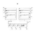
図1は本発明の第1の実施形態によるコンピュータシステムの構成を示すブロック図である。 FIG. 1 is a block diagram showing the configuration of a computer system according to the first embodiment of the present invention.
本発明の第1の実施形態によるコンピュータシステムは、複数の物理サーバ111、112が、複数のアップストリームポートと複数のダウンストリームポートとを有するI/Oスイッチ141のアップストリームポートに接続され、I/Oスイッチ141のダウンストリームポートに複数のI/Oデバイス151〜153とサーバ間通信機構161とが接続され、物理サーバ111、112の上でOS101、102が稼働するように構成されている。物理サーバ111は、CPU121及びメモリ131を有して構成され、また、物理サーバ112も、同様で、CPU122及びメモリ132を有して構成されている。
In the computer system according to the first embodiment of the present invention, a plurality of
すなわち、本発明の第1の実施形態によるコンピュータシステムは、I/Oスイッチ141を経由して物理サーバ111、112と、I/Oデバイス151〜153とが接続されて構成されている。I/Oデバイス151〜153のそれぞれは、物理サーバ111と112との両者で共有して使用されるI/Oデバイスであっても、物理サーバ111または112のどちらかで占有して使用されるI/Oデバイスであってもよい。また、I/Oスイッチ141のダウンストリームポートには、本発明によるサーバ相互間の通信に利用するサーバ間通信機構161が接続されており、I/Oスイッチ141を経由して物理サーバ111及び112と接続されている。
That is, the computer system according to the first embodiment of the present invention is configured by connecting the
前述において、本発明の実施形態では、OSが稼働している物理サーバを2台、サーバ間通信機構を1台備えるとして示しているが、本発明は、物理サーバがさらに多数設けられてもよく、また、サーバ間通信機構を2台以上設けてもよい。これにより、2台のサーバの組でサーバ相互間の通信を行っている場合にも、他の2台のサーバの組でサーバ相互間の通信を並行して行うことが可能となる。 In the above description, the embodiment of the present invention shows that two physical servers on which the OS is operating and one server-to-server communication mechanism are provided. However, the present invention may include a larger number of physical servers. Two or more inter-server communication mechanisms may be provided. Thereby, even when communication between servers is performed by a set of two servers, communication between servers can be performed in parallel by another set of two servers.
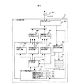
図2はサーバ間通信機構161の構成を示すブロック図である。サーバ間通信機構161は、I/Oリンク201によってI/Oスイッチ141と接続されている。I/Oリンク201とサーバ間通信機構161との内部は、I/Oインタフェース202により接続されている。
FIG. 2 is a block diagram showing the configuration of the
サーバ間通信機構161は、物理サーバ内のメモリデータを取り込むためのメモリ読み出し命令生成部203と、メモリデータを他の物理サーバに送り出すためのメモリ書き込み命令生成部204と、割り込みを発生させるための割り込み命令生成部205とを有している。メモリ読み出し命令生成部203、メモリ書き込み命令生成部204、割り込み命令生成部205には、命令を正しい宛先の物理サーバに送出するための宛先情報付加機構として、それぞれ送信側サーバ宛先情報付加部206と受信側サーバ宛先情報付加部207とが接続されている。また、サーバ間通信機構161は、メモリ読み出し命令生成部203、メモリ書き込み命令生成部204及び割り込み命令生成部205の動作を制御するために命令発行用シーケンサ208を備えている。また、サーバ間通信機構161は、メモリ読み出し命令により、物理サーバから読み出されたデータを取り込むためのメモリデータ返却命令受信部209を備えると共に、ここで受信したメモリデータを格納するためのメモリデータバッファ210を備えている。さらに、サーバ間通信機構161は、ソフトウェアからサーバ間通信機構を制御するための機構として、サーバ間通信機構レジスタ211を備えている。このサーバ間通信機構レジスタ211には、送信メモリアドレスレジスタ212、受信メモリアドレスレジスタ213、送信メモリ領域長レジスタ214、起動レジスタ215が含まれている。
The
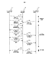
図3はサーバ間通信機構が物理サーバ相互間でメモリデータの転送を行う制御を説明するシーケンスチャートであり、次に、これについて説明する。ここでのメモリデータの転送は、図1に示すコンピュータシステムの例における物理サーバ111内のメモリ131に存在するデータを、物理サーバ112内のメモリ132に転送する場合を例としている。
FIG. 3 is a sequence chart for explaining the control in which the inter-server communication mechanism transfers the memory data between the physical servers. Next, this will be explained. The transfer of the memory data here is an example in which data existing in the memory 131 in the
(1)まず、データ送信側となる物理サーバ111上で稼働しているOS101が、送信するメモリ領域の先頭アドレスを設定する。この設定は、データ送信側となる物理サーバ111からサーバ間通信機構161の送信メモリアドレスレジスタ212に対して書き込み命令を送信することにより行われる(ステップ301)。
(1) First, the
(2)同様に、データ送信側となる物理サーバ111上で稼働しているOS101は、サーバ間通信機構161の送信メモリ領域長レジスタ214に対して書き込みを行い、送信するメモリ領域の大きさを設定する(ステップ302)。
(2) Similarly, the
(3)また、同様に、データ受信側となる物理サーバ112上で稼働しているOS102が、サーバ間通信機構161の受信メモリアドレスレジスタ213に対して書き込みを行い、受信するメモリ領域の先頭アドレスを設定する(ステップ303)。
(3) Similarly, the
前述までの処理でサーバ間通信を行うための初期設定処理が完了する。 The initial setting process for performing server-to-server communication is completed by the processes described above.
(4)次に、データ送信側となる物理サーバ111上で稼働しているOS101が、サーバ間通信機構161の起動レジスタ215に書き込みを行うことにより、サーバ間通信機構161を起動させる(ステップ304)。
(4) Next, the
(5)サーバ間通信機構161は、起動されると命令発行用シーケンサ208が動作を開始し、メモリ読み出し命令生成部203から送信側サーバ宛先情報付加部206を経由してデータ送信側の物理サーバ111の宛先情報を付加し、メモリ読み出し命令を発行する。このメモリ読み出し命令は、I/Oスイッチ141を通過する際に前記の送信側サーバ宛先情報を用いてデータ送信側の物理サーバ111へと正しく送信される(ステップ305a)。
(5) When the server-to-
(6)メモリ読み出し命令を受け取ったデータ送信側の物理サーバ111は、サーバ間通信機構161に対して、送信するメモリデータを含むデータ返却命令を送信することにより、ステップ305aでのメモリ読み出し命令に対するメモリデータ返却を行う。なお、1回のデータ返却命令で送信するメモリデータの量は、予め定められた量であり、送信すべきメモリ領域内のデータ量が大きい場合には、複数回に分けて送信される(ステップ306a)。
(6) The
(7)サーバ間通信機構161は、データ返却命令をメモリデータ返却命令受信部209で受信し、メモリデータ部分をメモリデータバッファ210に格納する。そして、サーバ間通信機構161は、メモリデータを受け取ると、メモリ書き込み命令生成部204がメモリデータバッファ210からメモリデータを取り出し、受信側サーバ宛先情報付加部207を経由してデータ受信側の物理サーバ112の宛先情報を付加し、転送すべきメモリデータを含むメモリ書き込み命令を発行する。このメモリ書き込み命令は、I/Oスイッチ141を通過する際に前記の受信側サーバ宛先情報を用いてデータ受信側の物理サーバ112へと正しく送信される(ステップ307a)。
(7) The
(8)命令発行用シーケンサ208は、前述したステップ305aでのメモリ読み出し命令の送信、ステップ306aでのメモリ返却命令の受信、ステップ307aでのメモリ書き込み命令の送信の一連の動作を、送信メモリ領域長レジスタ214で指定されたデータ長を転送し終えるまで繰り返すことにより、データ送信側の物理サーバ111からデータ受信側の物理サーバ112へデータの転送を行う(ステップ305b、306b、307b)。
(8) The
前述したステップ305b、306b、307bの処理を指定されたデータ長を転送し終えるまで繰り返すことにより、データ送受信の処理が完了する。
By repeating the above-described
(9)データの転送が終了すると、サーバ間通信機構161の命令発行用シーケンサ208は、割り込み命令生成部205を起動する。割り込み命令生成部205は、データ送信側の物理サーバ111及びデータ受信側の物理サーバ112のそれぞれに対して、データ送信完了を通知する割り込み命令を発行する。割り込み命令生成部205で生成された割り込み命令は、送信側サーバ宛先情報付加部206あるいは受信側サーバ宛先情報付加部207を経由して正しい宛先情報が付加され、それぞれデータ送信側の物理サーバ111、データ受信側の物理サーバ112へ送信される(ステップ308、309)。
(9) When the data transfer ends, the
前述したステップ308、309の処理を行うことにより、サーバ間でのデータ転送処理の全てが完了する。
By performing the processing of
前述した本発明の第1の実施形態では、サーバ間通信機構161に設定指示をしたり、サーバ間通信機構を起動したりする動作主体をOSであるとして説明したが、動作主体は、サーバ間通信機構用のデバイスドライバであっても、アプリケーションプログラム等であっても、仮想サーバを管理するハイパバイザ等であってもよい。
In the first embodiment of the present invention described above, the operating entity that issues a setting instruction to the
また、図3に示す処理を開始する契機となるのは、図1に示していないが、物理サーバ111、112に接続されている管理用のコンピュータからの指示であっても、また、物理サーバ111、112の中に構築されているサービスプロセッサからの指示であってもよい。また、この指示は、管理用のコンピュータ、サービスプロセッサが、物理サーバの状態から自動的に行われるものであっても、システム管理者等から行われるものであってもよい。
The trigger for starting the processing shown in FIG. 3 is not shown in FIG. 1, but may be an instruction from a management computer connected to the
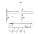
図4は本発明の第2の実施形態によるコンピュータシステムの構成を示すブロック図である。図4に示す本発明の第2の実施形態は、I/Oスイッチ内にサーバ間通信機構を設けるようにした例である。 FIG. 4 is a block diagram showing a configuration of a computer system according to the second embodiment of the present invention. The second embodiment of the present invention shown in FIG. 4 is an example in which an inter-server communication mechanism is provided in an I / O switch.
図1〜図3により説明した本発明の第1の実施形態は、サーバ間通信機構161を外付けのI/Oデバイスとして、I/Oスイッチ141のダウンストリームポートに接続するものとして説明したが、本発明の第2の実施形態は、図4に示すように、I/Oスイッチにサーバ間通信機構421を内蔵させて通信機構内蔵I/Oスイッチ411として構成し、物理サーバ401及び402相互間のデータ転送を行うようにしたものである。
The first embodiment of the present invention described with reference to FIGS. 1 to 3 is described as connecting the
本発明の第2の実施形態は、このように構成することにより、通信機構内蔵I/Oスイッチ411内のサーバ間通信機構421により、図3により説明した場合と同様に、物理サーバ401、402相互間の通信を行うことが可能となる。
In the second embodiment of the present invention, the
前述した本発明の第2の実施形態は、サーバ間通信機構421を接続するためにのために、I/Oスイッチのダウンストリームスロットを占有する必要がなくなり、他のデバイスのためにI/Oスイッチのダウンストリームスロットを開放することができるという利点を得ることができる。また、サーバ間通信機構421を外付けのデバイスとして用意する必要がないため、サーバ間通信を導入するコストをより低減することができるという利点を得ることができる。
The above-described second embodiment of the present invention eliminates the need to occupy the downstream slot of the I / O switch in order to connect the
図5は本発明の第3の実施形態によるコンピュータシステムの構成を示すブロック図である。図5に示す本発明の第3の実施形態は、物理サーバに接続するI/Oデバイスの数を増加するために、通信機構内蔵I/Oスイッチを多段に設けて構成した場合のコンピュータシステムの例である。 FIG. 5 is a block diagram showing a configuration of a computer system according to the third embodiment of the present invention. The third embodiment of the present invention shown in FIG. 5 is a computer system in a case where I / O devices with built-in communication mechanisms are provided in multiple stages in order to increase the number of I / O devices connected to a physical server. It is an example.
図5に示す本発明の第3の実施形態によるコンピュータシステムは、複数の物理サーバ501、502が1段目の通信機構内蔵I/Oスイッチのアップストリームポートに接続され、複数の2段目の通信機構内蔵I/Oスイッチ512、513が1段目の通信機構内蔵I/Oスイッチのダウンストリームポートに接続され、2段目の通信機構内蔵I/Oスイッチ512、513のそれぞれの複数のダウンストリームポートにI/Oデバイスが接続されて構成されている。そして、物理サーバ501と502との間のサーバ間通信は、初段の通信機構内蔵I/Oスイッチ511に内蔵したサーバ間通信機構521を用いて行うことができる。
In the computer system according to the third embodiment of the present invention shown in FIG. 5, a plurality of
前述の本発明の第3の実施形態によれば、初段のI/Oスイッチ内のサーバ間通信機構を用いてサーバ間通信を行うことができるので、図6により後述するI/Oスイッチにサーバ間通信機構を内蔵していないI/Oスイッチを多段に設けて構成した例に比較して、サーバ間通信に要する通信レイテンシを低減することができる。 According to the third embodiment of the present invention described above, server-to-server communication can be performed using the inter-server communication mechanism in the first stage I / O switch. Communication latency required for server-to-server communication can be reduced as compared to an example in which I / O switches that do not include an inter-server communication mechanism are provided in multiple stages.
図5に示す本発明の第3の実施形態によるコンピュータシステムは、初段の通信機構内蔵I/Oスイッチ511を1台だけ備えて構成されているが、この例では、初段の通信機構内蔵I/Oスイッチ511を複数台設けることも可能であり、また、2段目の通信機構内蔵I/Oスイッチ512、513を3台以上設けて構成することができる。このように構成された本発明の第3の実施形態は、2段目の通信機構内蔵I/Oスイッチの1つに複数の初段の通信機構内蔵I/Oスイッチを接続するような構成をとることにより、異なる初段の通信機構内蔵I/Oスイッチ内のサーバ間通信機構を用いては通信を行うことができない物理サーバ間の通信を、2段目の通信機構内蔵I/Oスイッチに内蔵したサーバ間通信機構を用いて行うことができる。
The computer system according to the third embodiment of the present invention shown in FIG. 5 includes only one first-stage communication mechanism built-in I /
図6は本発明の第4の実施形態によるコンピュータシステムの構成を示すブロック図である。図6に示す本発明の第4の実施形態は、物理サーバに接続するI/Oデバイスの数を増加させるために、I/Oスイッチとして、サーバ間通信機構を内蔵していないI/Oスイッチを多段(図示例では2段)に設け、2段目のI/Oスイッチにサーバ間通信機構を接続して構成した例である。 FIG. 6 is a block diagram showing a configuration of a computer system according to the fourth embodiment of the present invention. The fourth embodiment of the present invention shown in FIG. 6 is an I / O switch that does not incorporate a server-to-server communication mechanism as an I / O switch in order to increase the number of I / O devices connected to a physical server. Is provided in multiple stages (two stages in the illustrated example), and the inter-server communication mechanism is connected to the second stage I / O switch.
すなわち、図6に示す例は、複数の物理サーバ501、502を1段目のI/Oスイッチ611に接続し、このI/Oスイッチ611に複数の2段目のI/Oスイッチ612、613を接続し、2段目のI/Oスイッチ612、613にI/Oデバイスとサーバ間通信機構を接続して構成されている。
In other words, in the example illustrated in FIG. 6, a plurality of
図6に示す本発明の第4の実施形態によるコンピュータシステムは、I/Oスイッチにサーバ間通信機構を内蔵していないI/Oスイッチを多段に設けて構成しているため、物理サーバ501と502との間のサーバ間通信は、2段目のI/Oスイッチ612に接続されたサーバ間通信機構622で行う必要がある。なお、図6には示していないが、2段目のI/Oスイッチ613にもサーバ間通信機構を接続することができる。
The computer system according to the fourth embodiment of the present invention shown in FIG. 6 has a configuration in which I / O switches that do not incorporate inter-server communication mechanisms are provided in multiple stages in the I / O switch. It is necessary to perform server-to-server communication with the
前述した本発明の各実施形態は、サーバ間通信機構によるデータ送受信の処理の完了を、割り込み命令生成部からデータ送信側の物理サーバ及びデータ受信側の物理サーバに割り込み命令を発行するすることにより、各物理サーバに通知するものであったが、本発明は、データ送信処理の完了を他の方法により、各物理サーバに通知するようにすることもできる。 In each of the embodiments of the present invention described above, the completion of data transmission / reception processing by the inter-server communication mechanism is issued by issuing an interrupt command from the interrupt command generation unit to the physical server on the data transmission side and the physical server on the data reception side. However, according to the present invention, the completion of the data transmission process can be notified to each physical server by another method.
図7はサーバ間通信機構が物理サーバ相互間でメモリデータの転送を制御する他の例を説明するシーケンスチャートであり、次に、これについて説明する。ここでのメモリデータの転送は、図3に示して説明した場合と同様に、図1に示すコンピュータシステムの例における物理サーバ111内のメモリ131に存在するデータを、物理サーバ112内のメモリ132に転送する場合を例としている。
FIG. 7 is a sequence chart for explaining another example in which the inter-server communication mechanism controls the transfer of memory data between physical servers, which will be described next. As in the case described with reference to FIG. 3, the transfer of the memory data here is performed by using the data existing in the memory 131 in the
そして、この例においては、サーバ間通信機構161内のサーバ間通信機構レジスタ211に、データ送信側の物理サーバからもデータ受信側の物理サーバからも共通して読み出すことが可能な完了ステータスレジスタを設け、データ送受信処理を終了すると、サーバ間通信機構161が、サーバ間通信機構レジスタ211内に設けた完了ステータスレジスタに完了を登録するようにし、物理サーバが、完了ステータスレジスタへのポーリングにより、完了ステータスレジスタを読み出すことにより、送信側及び受信側の物理サーバがデータの転送の終了を知るようにコンピュータシステムが構成される。
In this example, the inter-server
図7に示すシーケンスにおけるステップ301〜307bまでの処理は、図3に示して説明したと同一であるので、ここまでの説明については省略する。
Since the processing from
(1)ステップ301〜307bまでの処理でデータの送受信処理が完了すると、サーバ間通信機構161が、サーバ間通信機構レジスタ211内に設けた完了ステータスレジスタに完了を登録する。その後、サーバ間通信機構161は、データ送信側物理サーバ111から完了ステータスレジスタの読み出し命令を受け取って、完了ステータスレジスタの内容をデータ送信側物理サーバ111に返却する(ステップ701、702)。
(1) When the data transmission / reception processing is completed in
(2)同様に、サーバ間通信機構161は、データ受信側物理サーバ112からも完了ステータスレジスタの読み出し命令を受け取って、完了ステータスレジスタの内容をデータ受信側物理サーバ112に返却する(ステップ703、704)。
(2) Similarly, the
前述では、完了ステータスレジスタを用いる例を説明したが、本発明は、サーバ通信機構161内の単一のレジスタに対して、データ送信側物理サーバ111からもデータ受信側物理サーバ112からも同様に読み出しまたは書き込みといったアクセスを可能とすることにより、サーバ間通信機構で単一のレジスタの状態を変更することにより、データ送信側物理サーバ及びデータ受信側物理サーバの両者にその状態を通知するようにすることができる。
Although the example using the completion status register has been described above, the present invention similarly applies to a single register in the
前述した本発明の実施形態での各処理は、プログラムにより構成し、本発明が備えるサーバ間通信機構に実行させることができ、また、それらのプログラムは、FD、CDROM、DVD等の記録媒体に格納して提供することができ、また、ネットワークを介してディジタル情報により提供することができる。 Each process in the above-described embodiment of the present invention is configured by a program and can be executed by the inter-server communication mechanism provided in the present invention. These programs are stored in a recording medium such as an FD, a CDROM, and a DVD. It can be stored and provided, or can be provided by digital information via a network.
前述した本発明の実施形態によれば、物理サーバ間のデータ転送を行う際に、従来は物理サーバ毎に用意していたサーバ間通信用の外付けI/Oデバイスの数を削減することができ、また、サーバ間通信機構をI/Oスイッチに内蔵することにより、サーバ間通信用の外付けI/Oデバイスを不要とすることができる。 According to the above-described embodiment of the present invention, when data transfer between physical servers is performed, the number of external I / O devices for server-to-server communication that have been conventionally prepared for each physical server can be reduced. In addition, by incorporating the inter-server communication mechanism in the I / O switch, it is possible to eliminate the need for an external I / O device for inter-server communication.
また、本発明の実施形態によれば、物理サーバ間のデータ通信は、サーバ間通信機構の内部で行うことができるため、プロトコル変換のオーバヘッドが生じることがなく、通信スループットやレイテンシの面で有利となる。 In addition, according to the embodiment of the present invention, data communication between physical servers can be performed inside the inter-server communication mechanism, so there is no overhead of protocol conversion, which is advantageous in terms of communication throughput and latency. It becomes.
さらに、本発明の実施形態によれば、サーバ間通信機構をI/Oスイッチに内蔵することにより、物理サーバ毎にサーバ間通信を行うための外付けのI/Oデバイスを用意する必要がなく、サーバ間通信を行うための導入コストを抑えることができる。また、I/Oスイッチのスロットがサーバ間通信用のI/Oデバイスで占有されることがなく、I/Oスロットを有効に活用することが可能となる。また、I/Oスイッチを多段の構成にしてI/Oデバイスの数を増加させたシステムにおいて、中継段のI/Oスイッチにもサーバ間通信機構を内蔵させることができるため、中継段のI/Oスイッチに接続された物理サーバ間のサーバ間通信は、中継段のI/Oスイッチ内蔵のサーバ間通信機構で折り返すことが可能であり、通信レイテンシをより低減することができる。 Furthermore, according to the embodiment of the present invention, it is not necessary to prepare an external I / O device for performing inter-server communication for each physical server by incorporating the inter-server communication mechanism in the I / O switch. The introduction cost for performing the communication between servers can be suppressed. Further, the slot of the I / O switch is not occupied by the I / O device for server-to-server communication, and the I / O slot can be used effectively. Further, in a system in which the number of I / O devices is increased with a multi-stage I / O switch, the inter-server communication mechanism can be built in the relay stage I / O switch. Inter-server communication between physical servers connected to the / O switch can be turned back by the inter-server communication mechanism built in the I / O switch in the relay stage, and communication latency can be further reduced.
また、本発明の実施形態によれば、アドレス変換を必要とせずに大量のメモリデータをサーバ間で転送するような用途で特に効果がある。例えば、仮想サーバのメモリイメージは、大容量であり、かつ、物理アドレスで連続領域であることがある。このような場合に、ハイパバイザが本発明によるサーバ間通信機構を使用して、仮想サーバのマイグレーションを物理サーバ間で行うといった用途に本発明を適用して大きな効果を得ることができる。 Further, according to the embodiment of the present invention, it is particularly effective in an application in which a large amount of memory data is transferred between servers without requiring address translation. For example, a memory image of a virtual server may have a large capacity and a continuous area with a physical address. In such a case, the present invention can be applied to an application in which a hypervisor uses a server-to-server communication mechanism according to the present invention to migrate a virtual server between physical servers.
101、102 OS
111、112、401、402、501、502 物理サーバ
121、122 CPU
131、132 メモリ
141、611、612、613 I/Oスイッチ
151〜153 I/Oデバイス
161、421、511、522、523、622 サーバ間通信機構
201 I/Oリンク
202 I/Oインタフェース
203 メモリ読み出し命令生成部
204 メモリ書き込み命令生成部
205 割り込み命令生成部
206 送信側サーバ宛先情報付加部
207 受信側サーバ宛先情報付加部
208 命令発行用シーケンサ
209 メモリデータ返却命令受信部
210 メモリデータバッファ
211 サーバ間通信機構レジスタ
212 送信メモリアドレスレジスタ
213 受信メモリアドレスレジスタ
214 送信メモリ領域長レジスタ
215 起動レジスタ
411、511、512、513 通信機構内蔵I/Oスイッチ
101, 102 OS
111, 112, 401, 402, 501, 502
131, 132
Claims (6)
前記I/Oスイッチのダウンストリームポートには、請求項1記載のサーバ間通信機構が接続されていることを特徴とするコンピュータシステム。 Each of the plurality of physical servers includes a plurality of physical servers each having one or more CPUs and a memory, and an I / O switch having a plurality of upstream ports and one or more downstream ports. In a computer system connected via an upstream port of an I / O switch,
The computer system according to claim 1, wherein the inter-server communication mechanism according to claim 1 is connected to a downstream port of the I / O switch.
前記I/Oスイッチには、請求項1記載のサーバ間通信機構が内蔵されており、前記ダウンストリームポートにはI/Oデバイスが接続されていることを特徴とするコンピュータシステム。 Each of the plurality of physical servers includes a plurality of physical servers each having one or more CPUs and a memory, and an I / O switch having a plurality of upstream ports and one or more downstream ports. In a computer system connected via an upstream port of an I / O switch,
The computer system according to claim 1, wherein the I / O switch includes the inter-server communication mechanism according to claim 1, and an I / O device is connected to the downstream port.
前記I/Oスイッチが多段に接続され、最上位の前記I/Oスイッチのアップストリームポートに前記物理サーバが接続され、多段に接続された前記I/Oスイッチのそれぞれには、請求項1記載のサーバ間通信機構が内蔵されていることを特徴とするコンピュータシステム。 Each of the plurality of physical servers includes a plurality of physical servers each having one or more CPUs and a memory, and an I / O switch having a plurality of upstream ports and one or more downstream ports. In a computer system connected via an upstream port of an I / O switch,
The I / O switch is connected in multiple stages, the physical server is connected to the upstream port of the highest I / O switch, and each of the I / O switches connected in multiple stages is claimed in claim 1. A computer system having a built-in inter-server communication mechanism.
Priority Applications (2)
| Application Number | Priority Date | Filing Date | Title |
|---|---|---|---|
| JP2008136943A JP2009282917A (en) | 2008-05-26 | 2008-05-26 | Interserver communication mechanism and computer system |
| US12/470,752 US20090292856A1 (en) | 2008-05-26 | 2009-05-22 | Interserver communication mechanism and computer system |
Applications Claiming Priority (1)
| Application Number | Priority Date | Filing Date | Title |
|---|---|---|---|
| JP2008136943A JP2009282917A (en) | 2008-05-26 | 2008-05-26 | Interserver communication mechanism and computer system |
Publications (1)
| Publication Number | Publication Date |
|---|---|
| JP2009282917A true JP2009282917A (en) | 2009-12-03 |
Family
ID=41342913
Family Applications (1)
| Application Number | Title | Priority Date | Filing Date |
|---|---|---|---|
| JP2008136943A Withdrawn JP2009282917A (en) | 2008-05-26 | 2008-05-26 | Interserver communication mechanism and computer system |
Country Status (2)
| Country | Link |
|---|---|
| US (1) | US20090292856A1 (en) |
| JP (1) | JP2009282917A (en) |
Cited By (5)
| Publication number | Priority date | Publication date | Assignee | Title |
|---|---|---|---|---|
| JP2012058866A (en) * | 2010-09-07 | 2012-03-22 | Hitachi Ltd | Computer system, inter-computer memory copy method, and switch |
| WO2012073304A1 (en) * | 2010-11-29 | 2012-06-07 | 株式会社日立製作所 | Computer system, and switch and packet transfer control method used therein |
| WO2012157103A1 (en) * | 2011-05-19 | 2012-11-22 | 株式会社日立製作所 | Multi-route switch, computer, and inter-computer communication method |
| WO2015015652A1 (en) * | 2013-08-02 | 2015-02-05 | 株式会社日立製作所 | Server system equipped with server-to-server communication mechanism and method for communication between multiple servers |
| JP2015522991A (en) * | 2012-05-14 | 2015-08-06 | アドバンスト・マイクロ・ディバイシズ・インコーポレイテッドAdvanced Micro Devices Incorporated | Server node interconnection device and server node interconnection method |
Families Citing this family (1)
| Publication number | Priority date | Publication date | Assignee | Title |
|---|---|---|---|---|
| DE102012102198A1 (en) * | 2012-03-15 | 2013-09-19 | Fujitsu Technology Solutions Intellectual Property Gmbh | Modular server system, I / O module and switching method |
Family Cites Families (2)
| Publication number | Priority date | Publication date | Assignee | Title |
|---|---|---|---|---|
| US20070041383A1 (en) * | 2005-04-05 | 2007-02-22 | Mohmmad Banikazemi | Third party node initiated remote direct memory access |
| JP4836533B2 (en) * | 2005-09-27 | 2011-12-14 | 株式会社日立製作所 | File system migration method in storage system, storage system, and management computer |
-
2008
- 2008-05-26 JP JP2008136943A patent/JP2009282917A/en not_active Withdrawn
-
2009
- 2009-05-22 US US12/470,752 patent/US20090292856A1/en not_active Abandoned
Cited By (6)
| Publication number | Priority date | Publication date | Assignee | Title |
|---|---|---|---|---|
| JP2012058866A (en) * | 2010-09-07 | 2012-03-22 | Hitachi Ltd | Computer system, inter-computer memory copy method, and switch |
| WO2012073304A1 (en) * | 2010-11-29 | 2012-06-07 | 株式会社日立製作所 | Computer system, and switch and packet transfer control method used therein |
| US9396150B2 (en) | 2010-11-29 | 2016-07-19 | Hitachi, Ltd. | Computer system and method utilizing a PCIe switch to control transfer of packets |
| WO2012157103A1 (en) * | 2011-05-19 | 2012-11-22 | 株式会社日立製作所 | Multi-route switch, computer, and inter-computer communication method |
| JP2015522991A (en) * | 2012-05-14 | 2015-08-06 | アドバンスト・マイクロ・ディバイシズ・インコーポレイテッドAdvanced Micro Devices Incorporated | Server node interconnection device and server node interconnection method |
| WO2015015652A1 (en) * | 2013-08-02 | 2015-02-05 | 株式会社日立製作所 | Server system equipped with server-to-server communication mechanism and method for communication between multiple servers |
Also Published As
| Publication number | Publication date |
|---|---|
| US20090292856A1 (en) | 2009-11-26 |
Similar Documents
| Publication | Publication Date | Title |
|---|---|---|
| JP7774092B2 (en) | Unified address space for multiple hardware accelerators with dedicated low latency links | |
| EP4002139B1 (en) | Memory expander, host device using memory expander, and operation method of server system including memory expander | |
| US6421742B1 (en) | Method and apparatus for emulating an input/output unit when transferring data over a network | |
| US7664909B2 (en) | Method and apparatus for a shared I/O serial ATA controller | |
| JP5363064B2 (en) | Method, program and apparatus for software pipelining on network on chip (NOC) | |
| US5802333A (en) | Network inter-product stacking mechanism in which stacked products appear to the network as a single device | |
| CN112867998B (en) | Operation accelerator, switch, task scheduling method and processing system | |
| JP2003084919A (en) | Disk array device control method and disk array device | |
| WO2021012169A1 (en) | Method of improving reliability of storage system, and related apparatus | |
| US20250165309A1 (en) | System and method for managing namespace of offloading card and processing input/output request | |
| JP2009282917A (en) | Interserver communication mechanism and computer system | |
| KR20240122168A (en) | Storage-integrated memory expander, computing system based compute express link, and operating method thereof | |
| CN119597489A (en) | P2P communication method and system between IO devices based on PCIe-NTB | |
| CN100495312C (en) | Storage control system and its processing nodes | |
| JP2006039897A (en) | Multi-node system, inter-node crossbar switch, node, switch program and node program | |
| EP2370897A2 (en) | Composite device emulation | |
| JP2007065751A (en) | Storage system and storage control method | |
| US20130151885A1 (en) | Computer management apparatus, computer management system and computer system | |
| KR102353930B1 (en) | Disaggregated memory appliance | |
| CN118708368B (en) | Data processing method and device for distributed memory computing engine cluster | |
| CN120780639A (en) | CXL host controller, data transmission method and computer | |
| JP2019192217A (en) | Information processing system | |
| CN113986457B (en) | Interrupt mapping device and method for remote input/output equipment | |
| CN101290556A (en) | Disk Array Shared Device | |
| JP3508857B2 (en) | Data transfer method between nodes and data transfer device |
Legal Events
| Date | Code | Title | Description |
|---|---|---|---|
| A621 | Written request for application examination |
Free format text: JAPANESE INTERMEDIATE CODE: A621 Effective date: 20100608 |
|
| A761 | Written withdrawal of application |
Free format text: JAPANESE INTERMEDIATE CODE: A761 Effective date: 20111019 |