JP2009287657A - Working vehicle - Google Patents
Working vehicle Download PDFInfo
- Publication number
- JP2009287657A JP2009287657A JP2008140453A JP2008140453A JP2009287657A JP 2009287657 A JP2009287657 A JP 2009287657A JP 2008140453 A JP2008140453 A JP 2008140453A JP 2008140453 A JP2008140453 A JP 2008140453A JP 2009287657 A JP2009287657 A JP 2009287657A
- Authority
- JP
- Japan
- Prior art keywords
- pedal
- trunnion shaft
- reverse
- sensor
- continuously variable
- Prior art date
- Legal status (The legal status is an assumption and is not a legal conclusion. Google has not performed a legal analysis and makes no representation as to the accuracy of the status listed.)
- Withdrawn
Links
- 230000005540 biological transmission Effects 0.000 claims abstract description 56
- 230000002706 hydrostatic effect Effects 0.000 claims abstract description 23
- 230000007935 neutral effect Effects 0.000 claims abstract description 19
- 238000001514 detection method Methods 0.000 claims description 11
- 230000000994 depressogenic effect Effects 0.000 claims description 10
- 230000007246 mechanism Effects 0.000 abstract description 4
- 230000035939 shock Effects 0.000 abstract description 4
- 230000006866 deterioration Effects 0.000 abstract description 2
- 230000009471 action Effects 0.000 description 3
- 238000010586 diagram Methods 0.000 description 3
- 238000004891 communication Methods 0.000 description 2
- 230000008602 contraction Effects 0.000 description 2
- 238000003825 pressing Methods 0.000 description 2
- 230000008901 benefit Effects 0.000 description 1
- 230000008859 change Effects 0.000 description 1
- 238000010276 construction Methods 0.000 description 1
- 238000006073 displacement reaction Methods 0.000 description 1
- 238000012423 maintenance Methods 0.000 description 1
- 238000004519 manufacturing process Methods 0.000 description 1
- 238000000034 method Methods 0.000 description 1
- 230000004044 response Effects 0.000 description 1
- 230000035945 sensitivity Effects 0.000 description 1
Images


Landscapes
- Operation Control Of Excavators (AREA)
- Control Of Fluid Gearings (AREA)
Abstract
【課題】静油圧式無段変速装置の作動を機械的連動機構でなく電子制御機構により行い、常に正確に静油圧式無段変速装置を作動可能な走行車両を提供すること。
【解決手段】エンジンの動力を回動角度を調整して出力する静油圧式無段変速装置8のトラニオン軸8aの回動角度をピストンロッド6aのストローク長さを油圧シリンダ6で決めるが、前進ペダル1aと後進ペダル1bとの間でのペダル踏み込み位置の切り替え時にペダルセンサ3sが中立位置を検知すると、所定時間中立位置にトラニオン軸8aをとどめ、その後所定時間後にペダルセンサ3sで検知する前進ペダル1a又は後進ペダル1bの位置に応じたトラニオン軸8aの回動角度にする制御を行う。前進ペダル1aと後進ペダル1bとの間で速やかに踏み替え操作した場合であっても、変速ショックが著しくオペレータの体が揺られフィーリングが悪くなることがなく、また、機械部品の耐久性の劣化を防止できる。
【選択図】図5An object of the present invention is to provide a traveling vehicle in which a hydrostatic continuously variable transmission is operated not by a mechanical interlocking mechanism but by an electronic control mechanism so that the hydrostatic continuously variable transmission can always be operated accurately.
A rotation angle of a trunnion shaft 8a of a hydrostatic continuously variable transmission 8 that outputs engine power by adjusting a rotation angle is determined by a hydraulic cylinder 6 while a stroke length of a piston rod 6a is determined by a hydraulic cylinder 6. When the pedal sensor 3s detects the neutral position when the pedal depression position is switched between the pedal 1a and the reverse pedal 1b, the forward pedal is detected by the pedal sensor 3s after a predetermined time, and the trunnion shaft 8a remains at the neutral position for a predetermined time. Control is performed to turn the trunnion shaft 8a according to the position of 1a or the reverse pedal 1b. Even when the pedal is quickly switched between the forward pedal 1a and the reverse pedal 1b, the shift shock does not occur so much that the operator's body is shaken and the feeling is not deteriorated. Deterioration can be prevented.
[Selection] Figure 5
Description
この発明は、静油圧式無段変速装置と噛合式変速装置からなる変速装置を有する農業用、建築用、運搬用等のトラクタなどの作業車両に関する。 The present invention relates to a work vehicle such as a tractor for agriculture, construction, transportation, etc. having a transmission comprising a hydrostatic continuously variable transmission and a meshing transmission.
従来、トラクタ等の作業車両において、主変速装置の変速方式として静油圧式無段変速装置の可変容量型の油圧ポンプの可動斜板を主変速レバーと連動連結して、該主変速レバーを回動することにより油圧ポンプからの吐出量を変更して出力回転数を変更する変速方式が知られている。この静油圧式無段変速装置は前進ペダルと後進ペダルをそれぞれ踏むことで車両を前進又は後進させる方向にトラニオン軸を回転させる方式である。
特許文献1記載の作業車両では前進ペダルと後進ペダルをそれぞれ踏むことで車両を前進又は後進させる方向に静油圧式無段変速装置のトラニオン軸を回転させる構成であるが、作業車両の中立位置は前進ペダルと後進ペダルを踏み込まない時に設定されている。
The work vehicle described in
しかしながら、前進ペダル(後進ペダル)を踏んでいる状態から後進ペダル(前進ペダル)に速やかに踏み変えた場合、トラニオン軸が一気に中立位置を通過するので変速ショックが発生する不具合があった。
本発明の課題は、静油圧式無段変速装置の作動を機械的連動機構でなく電子制御機構により行い、しかも変速ショックのない静油圧式無段変速装置を作動可能にする走行車両を提供することである。
However, when the forward pedal (reverse pedal) is pressed down to the reverse pedal (forward pedal) quickly, the trunnion shaft passes through the neutral position all at once.
An object of the present invention is to provide a traveling vehicle in which the operation of a hydrostatic continuously variable transmission is performed not by a mechanical interlocking mechanism but by an electronic control mechanism, and in addition, the hydrostatic continuously variable transmission without shift shock can be operated. That is.
請求項1記載の発明は、エンジンと、該エンジンの動力を斜板の回動角度を調整して出力するトラニオン軸(8a)を有する静油圧式無段変速装置(8)と、静油圧式無段変速装置(8)のトラニオン軸(8a)の回動角度をピストンロッド(6a)のストローク長さで決めるトラニオン軸回動用油圧シリンダ(6)と、該トラニオン軸回動用油圧シリンダ(6)のピストンロッド(6a)のストローク長を検出するストローク長さ検出センサ(7s)と、前進時に踏み込む前進ペダル(1a)及び後進時に踏み込む後進ペダル(1b)と、前進ペダル(1a)及び後進ペダル(1b)の踏み込み位置を検出するペダルセンサ(3s)と、該ペダルセンサ(3s)で検出する前進ペダル(1a)又は後進ペダル(1b)の踏み込み位置に対応してトラニオン軸回動用油圧シリンダ(6)のピストンロッド(6a)のストロークによりトラニオン軸(8a)の回動角度の調整を行い、かつペダルセンサ(3s)で前進ペダル(1a)と後進ペダル(1b)との間でのペダル踏み込み位置の切り替え時にペダルセンサ(3s)が中立位置を検知すると、所定時間中立位置にトラニオン軸(8a)をとどめ、その後所定時間後にペダルセンサ(3s)で検知する前進ペダル(1a)又は後進ペダル(1b)の位置に応じたトラニオン軸(8a)の回動角度にする制御を行う制御装置(5)とを設けた作業車両である。
The invention described in
本発明によれば、制御装置(5)は前進ペダル(1a)から後進ペダル(1b)に、又は後進ペダル(1b)から前進ペダル(1a)に素早く(一方側のペダルを踏んでいる状態から足を離し、直ぐに他方側のペダルを踏む状況)ペダル踏み替え操作した場合は、ペダルが踏まれていてもトラニオン軸(8a)を一旦中立域に調節保持し、所定時間後(例えば、0.3秒後)に前進域或いは後進域を検出するアクセルペダルセンサ(7s)に対応するトラニオン軸(8a)の回動角度になるようにする。 According to the present invention, the control device (5) moves from the forward pedal (1a) to the reverse pedal (1b) or from the reverse pedal (1b) to the forward pedal (1a) quickly (from a state where the pedal on one side is depressed). When the pedal is switched, the trunnion shaft (8a) is once adjusted and held in the neutral range even if the pedal is depressed, and after a predetermined time (for example, 0. 0). After 3 seconds, the rotation angle of the trunnion shaft (8a) corresponding to the accelerator pedal sensor (7s) for detecting the forward or reverse range is set.
本発明によれば、前進ペダル1aと後進ペダル1bとの間で速やかに踏み替え操作した場合であっても、変速ショックが著しくオペレータの体が揺られフィーリングが悪くなることがなく、また、機械部品の耐久性の劣化を防止できる。
According to the present invention, even when the pedal is quickly switched between the
本発明の実施例を図面と共に説明する。
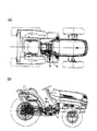
無段変速式作業車両の一例であるトラクタは、図7の平面図(a)及び側面図(b)に示すように、操縦部のフロア位置に静油圧式無段変速装置を内設したトランスミッション1を搭載し、その側方位置に前進ペダル1a及び後進ペダル1bを配置する。トランスミッション1は、エンジン(図示せず)から伝動される走行動力を無段階に変速して走行車輪に伝えて前後進走行車速を調節し、このトランスミッション1をそれぞれのペダル踏み込み操作に応じて変速制御するための伝動速度制御装置(図示せず)を設ける。
Embodiments of the present invention will be described with reference to the drawings.
A tractor, which is an example of a continuously variable work vehicle, is a transmission in which a hydrostatic continuously variable transmission is provided at a floor position of a control unit as shown in a plan view (a) and a side view (b) of FIG. 1 is mounted, and a
図1は、無段変速式作業車両の伝動速度制御装置のシステム構成図である。この伝動速度制御システムは、踏み込み操作可能に配置した前進ペダル1a及び後進ペダル1bの踏み込み動作を検出する入力側と、ペダル操作と対応するように、静油圧式無段変速装置8の速度調節部を目標速度位置に調節駆動する出力側と、入力側の検出信号に基づいて出力側の機器制御処理を行うコントローラ5とから構成される。
FIG. 1 is a system configuration diagram of a transmission speed control device for a continuously variable work vehicle. This transmission speed control system includes an input side for detecting the depression operation of the
前記伝動速度制御システムの入力側は、前進ペダル1a及び後進ペダル1bと、それぞれのペダル1a、1bに共通した回動中心である支軸1cと連結するロッド2a、2bと、これらロッド2a,2bの進退動作を共通の回転軸3cについて互いに異なる方向の回動動作に変換するクランクレバー3a,3bと、これらクランクレバー3a、3bの回動角によってペダル1a、1bの踏み込み位置を検出するペダルセンサ3sなどから構成されている。また前記伝動速度制御システムの入力側には、そのほかに必要に応じて車速センサ4a、図示しないエンジンの出力に対応したエンジンスロットル弁の開度を検出するスロットルセンサ4b、油圧シリンダ6を作動させる油温を検出する油温センサ4c等を設けることができ、各センサ4a〜4cのそれぞれの検出信号をデジタルコントローラ等からなる伝動速度制御部5に入力する。
The input side of the transmission speed control system includes a
前記伝動速度制御システムの出力側は、電磁式油圧制御弁9によって伸縮動作するアクチュエータである油圧シリンダ6と、そのピストンロッド6aの伸縮動作を受けて支軸7aについて回動動作するクランクレバー7と、このクランクレバー7の回動角によってトラニオン軸8aによる速度調節部の回動位置を検出するトラニオンセンサ7sと、同クランクレバー7からロッド7bを介して連結する静油圧式無段変速装置8とから構成する。この静油圧式無段変速装置8は、前後進静油圧式無段変速装置であり、その速度調節部であるトラニオン軸8aの回動角度によって伝動速度が調節されることにより作業車両の前後進と走行速度を無段階に調節する。
The output side of the transmission speed control system includes a
伝動速度制御部5の入力側の具体的な構成例を図2の斜視図で示す。図2に示すように、前進ペダル1aと後進ペダル1bとそれら操作を検出するペダルセンサ3sとペダル1a,1bとペダルセンサ3sの間の次に記す連結部材を単一のペダルリンクユニットとして構成する。
A specific configuration example on the input side of the transmission speed control unit 5 is shown in the perspective view of FIG. As shown in FIG. 2, the
図3の側面図に示すように、ペダルリンクユニットの内部には静油圧式無段変速装置8を内設し、トラクタ等の作業車両の車速を調節するトランスミッション1の側方部において、前進ペダル1a及び後進ペダル1bが共通の支軸1cに軸支され、互いに近接して並行配置され、それぞれのペダル1a,1bの動きを支軸1cに一端が固着したアジャスタ付きのロッド2a,2bに伝え、さらに該ロッド2a,2bの他端に一端が連結したクランクレバー3a,3bを作動させる。クランクレバー3a,3bの他端は共通の回転軸3cに互いに反対側から連結しており、ロッド2a又はロッド2bの進退動作を回転軸3cにより互いに異なる方向の回動動作に変換し、回転軸3cに一体に設けた作用アーム3eが作動すると、これに連動するペダルセンサ3sが回転軸3cの揺動角度、即ち、前進ペダル1a及び後進ペダル1bの踏み込み量を検出する。
As shown in the side view of FIG. 3, a hydrostatic continuously variable transmission 8 is provided inside the pedal link unit, and a forward pedal is provided at a side portion of the
前記ペダル1a,1b、ペダルセンサ3s及びロッド2a,2bは、トランスミッション1に対してマウント支持されたフロアFに取り付けられているので、トランスミッション1からの振動、即ち、機体側からの振動が抑制され、ペダルセンサ3sの検出精度が向上する。
Since the
上記ペダルリンクユニットの入力側のユニットにおいて、前進ペダル1aと後進ペダル1bの内の一方を踏み込み操作すると、対応するロッド2a,2b及びクランクレバー3a,3bを介して回転軸3cが回動し、回転軸3cの作用アーム3eを介してペダルセンサ3sがペダル踏み込み操作と対応する回転軸3cの回動角度を検出する。また、前進ペダル1aと後進ペダル1bの内の他方を踏み込み操作すると、対応するクランクレバー3a、3bが前記した回転軸3cの回転方向と逆方向に回動し、その結果ペダルセンサ3sにより逆方向の回動角度が検出される。
In the unit on the input side of the pedal link unit, when one of the
上記ペダルリンクユニットの出力側のユニットにおいては、図4の側面図に示すようにトランスミッション1の側面部に沿って油圧シリンダ6が配置され、そのピストンロッド6aと連結するクランクレバー7が支軸7aによって軸支され、このクランクレバー7の揺動角度を検出するトラニオンセンサ7sの一端が該レバー7に係止されている。クランクレバー7にはロッド7bの一端が連結し、該ロッド7bの他端にトランスミッション1のトラニオン軸8aと一体のクランクレバーであるトラニオンアーム8bが連結している。
In the output side unit of the pedal link unit, as shown in the side view of FIG. 4, a
従ってストローク長さ検出センサ7sがトラニオン軸回動用油圧シリンダ6のピストンロッド6aのストローク長を検出することができ、検出センサ7sによる検出値に応じてトラニオン軸8aが回動してペダル1a,1bの踏み込み量に応じた出力が静油圧式無段変速装置8から行われる。
Therefore, the stroke length detection sensor 7s can detect the stroke length of the piston rod 6a of the trunnion shaft rotation
これらペダルリンクユニットの出力側のユニットはトランスミッション1の側面部に取り付けられている。
このように出力側のユニットは上記入力側のユニットと並列位置に配置される。また、トラニオンアーム8bにはカム8cを形成し、トラニオンアーム8bをニュートラル位置に復帰させるようにニュートラルスプリング8dによってカム8cに作用するニュートラルアーム8eが取り付けられている。
The units on the output side of these pedal link units are attached to the side surface of the
Thus, the output side unit is arranged in parallel with the input side unit. Further, a
上記ペダルリンクユニットの出力側のユニット構成により、油圧制御される油圧シリンダ6のピストンロッド6aが進退動作するとクランクレバー7とロッド7bを介してトラニオンアーム8bと一体のトラニオン軸8aが回動されてトランスミッション1に内設した静油圧式無段変速装置8の可変油圧モータ(図示せず)の斜板が回動して伝動速度が調節され、トラニオン軸8aの調節位置を検出するトラニオンセンサ7sの信号に基づいて油圧シリンダ6を伸縮制御することにより、所要の速度調節が可能となる。また、油圧シリンダ6の制御油圧を開放すると、ニュートラルアーム8eの作用力を受けるカム8cによりトラニオンアーム8bが所定の中立位置に戻されて機体走行が停止される。
Due to the unit configuration on the output side of the pedal link unit, when the piston rod 6a of the
前進ペダル1a及び後進ペダル1bの踏み込み操作をペダルセンサ3sが検出すると、伝動速度制御部5は、ペダルセンサ3sの検出信号に応じてトラニオン軸8aの目標速度位置を決定し、トラニオン軸8aが目標速度位置に等しくなるまでトラニオンセンサ7sの信号に基づいて油圧シリンダ6を電磁式油圧切替(制御)弁9によって作動制御する。その結果、ペダル操作に応じて機体の走行車速を調節することができる。
When the
上記伝動速度制御部5は、その検出側の構成により共通のペダルセンサ3sを介して前進ペダル1a及び1bの個々の踏み込み動作量が検出されることから、個別ペダル仕様による2つのペダル1a,1bの踏み込み量に応じて無段階に車速調節をするための伝動速度制御装置を簡易な構成として、共通の操作性を確保しつつ、製造コストおよびメンテナンス負荷を軽減することができる。
The transmission speed control unit 5 detects the individual stepping operation amounts of the
本実施例では、図5のフローチャートに示すように作業者が前進ペダル1aから後進ペダル1b又は後進ペダル1bから前進ペダル1aと速やかに(素早く)踏み替え操作した場合は、トラニオン軸8aを一旦中立域に調節保持し、所定時間後(例えば、0.3秒後)、前進域又は後進域を検出するアクセルペダルセンサ3sに対応するトラニオンアーム8bの回転角度になるように構成している。さらに、油圧シリンダ6への出力の入り切りを繰り返すことで段階的に調節したり、パルス出力とすることで遅い速度で調節可能としている。
In this embodiment, as shown in the flowchart of FIG. 5, when the operator quickly (quickly) switches from the
前記「段階的に調節」するとは、油圧シリンダを作動させるバルブへの電気信号を入り切りすることで段階的に目標位置まで位置付けることであり、また、パルス出力することでゆっくりとした速度で目標位置まで位置付けるようにしてもよい。 The “adjustment in stages” means that the electric signal to the valve that operates the hydraulic cylinder is turned on and off to position the target position in stages, and the target position is output at a slow speed by outputting pulses. You may make it position to.
上記ペダル1a,1bを素早く踏み替え操作した場合に一定時間の間トラニオンアーム8bを中立域にとどめておかない場合は、変速ショックが大きくなり、作業者の体が揺られ、操作フィーリングが悪くなる。また、その上に機械部品にも負荷が掛かるため、耐久性も悪くなる。
If the
たまに作業者が走行中にエンジンキーをオフした後にブレーキを掛けて車両を止めることがある。この場合は次にエンジンキーを入れた時に、作業者の意図に反してアクセルペダルセンサ3sが中立域を検出していないため、油圧シリンダ6が前進側或いは後進側に調節されて車両が動いてしまうおそれがある。
Occasionally, an operator may turn off the engine key while driving to apply a brake to stop the vehicle. In this case, the next time the engine key is turned on, the
そこで、エンジンキーを入れた時に、一回のみ前進域あるいは後進域を検出するアクセルペダルセンサ3sが中立域を検出していない場合は、連続してブザーによる報知をするとともにトラニオン軸8aの作動用の油圧シリンダ6を作動させてセンサ3sの検出位置を中立位置に戻すように構成した。また、その後のトラニオン軸8aの作動制御の開始条件は、アクセルペダルセンサ3sが前進域あるいは後進域を検出してからとする構成した。こうして、トラニオン制御の安全性を従来より向上させることができる。
Therefore, when the
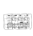
また、最近は車両の盗難事件が多発しており、その対策として本実施例では図6の平面図に示すようにトラクタの運転席にあるフロントスイッチパネルに工夫を施す構成とする。
このスイッチパネルは、エンジン始動後に多数のスイッチの中で特定のスイッチを順番に押したときに初めて制御コントローラ5が起動するソフトウエアを有する。すなわち、感度スイッチや水平切換スイッチをある特定の順番で押したとき、各制御が実行されるようにする。
In recent years, there have been many cases of vehicle theft. In this embodiment, the front switch panel in the driver's seat of the tractor is designed as shown in the plan view of FIG.
This switch panel has software that the controller 5 is activated only when a specific switch among a number of switches is sequentially pressed after the engine is started. That is, each control is executed when the sensitivity switch or the horizontal changeover switch is pressed in a specific order.
従って、多数のスイッチの中で各自が決めた順にスイッチを押して始めて制御コントローラ5が起動するので盗難防止になる。また、エンジンを切る前にスイッチの押す順序を変えることができるようにすると、さらに盗難(乗り逃げ)防止になる。この構成により盗難装置専用部品を備える必要がない利点もある。 Therefore, the controller 5 is activated only after the switches are pushed in the order determined by each of the switches, thereby preventing theft. Further, if the switch pressing order can be changed before the engine is turned off, theft (riding and escape) is further prevented. This configuration also has the advantage that it is not necessary to provide a dedicated device for theft device.
また、図6に示すフロントスイッチのパネルが外されている時は、制御コントローラ5は起動しない機能を設定可能しておくと盗難防止になる。前記制御コントローラ5が起動しないための機能の設定は、例えばフロントスイッチパネル内の特定のスイッチを押した状態でフロントスイッチパネルを外した場合などである。また、フロントスイッチパネル以外の本機側の特定のスイッチで行なうように構成してもよい。 Further, when the front switch panel shown in FIG. 6 is removed, the controller 5 can be prevented from being stolen by setting a function that does not start. The setting of the function for preventing the controller 5 from being activated is, for example, when the front switch panel is removed while a specific switch in the front switch panel is pressed. Further, a specific switch on the side of the machine other than the front switch panel may be used.
前記フロントスイッチのパネルが外されている時は、制御コントローラ5は起動しない構成を有効とするか無効にするかを決定する機能を構成してもよい。
この場合、前述した特定のスイッチを押さない状態でフロントスイッチパネルを外すと、制御コントローラ5が起動する構成とする。これにより、フロントスイッチパネルを外していても、例えば機体を移動させたい場合などは制御コントローラ5を起動させることができるので、作業者の意図を反映できるようになる。また、特定のスイッチは別の機能を持つスイッチと共用することになるので、スイッチの数を増やすことなく廉価な構成となる。
When the front switch panel is removed, the controller 5 may be configured to determine whether to enable or disable the configuration that does not start.
In this case, the controller 5 is activated when the front switch panel is removed without pressing the specific switch. Thereby, even if the front switch panel is removed, the control controller 5 can be activated when, for example, it is desired to move the machine body, so that the operator's intention can be reflected. In addition, since a specific switch is shared with a switch having another function, the configuration is inexpensive without increasing the number of switches.
また前記各種セキュリティのための機能が設定されているときに、これを無効に設定しようとしてもできない構成にすることで、よりセキュリティ機能が高まる。
例えば、エンジンキーを入れるとセキュリティ機能が作動し、このセキュリティ機能を無効にする入力(セキュリティ解除)が設定できないが、エンジンキーを入れてセキュリティ機能を作動させたとき特定のスイッチ(ユーザが自分で決めたスイッチ又は工場出荷時に決められた特定スイッチ)をセキュリティ解除スイッチとして、これを操作することでセキュリティ機能を解除できるようにして、セキュリティ機能の無効入力が設定できる。
Further, when the various functions for security are set, the security function is further enhanced by adopting a configuration in which it is impossible to set the function to invalid.
For example, when an engine key is inserted, the security function is activated, and an input (security release) that disables this security function cannot be set. However, when the engine key is activated and the security function is activated, a specific switch An invalid input of the security function can be set so that the security function can be canceled by operating the determined switch or the specific switch determined at the time of factory shipment as a security release switch.
このようなセキュリティ機能のスイッチによる設定を外部通信機器で設定できる構成にしても良い。この場合には、セキュリティ機能が設定されている間は外部通信機器で前記スイッチによる設定を不能にしておかないと、安全性がおびやかされる。 It may be configured such that setting by such a security function switch can be set by an external communication device. In this case, if the setting by the switch is not disabled in the external communication device while the security function is set, the safety is jeopardized.
セキュリティ機能の解除後に再びセキュリティ機能を設定させるためには、メインスイッチ(エンジン)キーが抜かれて、再度メインスイッチキーが差し込まれて、エンジンが始動した時に可能とすることで、エンジンを始動するたびにセキュリティ機能を解除する必要がなくなる。 In order to set the security function again after canceling the security function, the main switch (engine) key is removed, the main switch key is inserted again, and it is possible when the engine is started. It is no longer necessary to release the security function.
1 トランスミッション 1a 前進ペダル
1b 後進ペダル 1c 支軸
2a、2b ロッド
5 コントローラ(伝動速度制御部)
3a,3b クランクレバー
3c 回転軸 3e 作用アーム
3s ペダルセンサ 4a 車速センサ
4b スロットルセンサ 4c 油温センサ
6 油圧シリンダ 6a ピストンロッド
7 クランクレバー 7a 支軸
7b ロッド 7s トラニオンセンサ
8 静油圧式無段変速装置 8a トラニオン軸
8b トラニオンアーム 8c カム
8d ニュートラルスプリング
8e ニュートラルアーム
1
3a, 3b Crank lever 3c
Claims (1)
該エンジンの動力を斜板の回動角度を調整して出力するトラニオン軸(8a)を有する静油圧式無段変速装置(8)と、
静油圧式無段変速装置(8)のトラニオン軸(8a)の回動角度をピストンロッド(6a)のストローク長さで決めるトラニオン軸回動用油圧シリンダ(6)と、
該トラニオン軸回動用油圧シリンダ(6)のピストンロッド(6a)のストローク長を検出するストローク長さ検出センサ(7s)と、
前進時に踏み込む前進ペダル(1a)及び後進時に踏み込む後進ペダル(1b)と、
前進ペダル(1a)及び後進ペダル(1b)の踏み込み位置を検出するペダルセンサ(3s)と、
該ペダルセンサ(3s)で検出する前進ペダル(1a)又は後進ペダル(1b)の踏み込み位置に対応してトラニオン軸回動用油圧シリンダ(6)のピストンロッド(6a)のストロークによりトラニオン軸(8a)の回動角度の調整を行い、かつペダルセンサ(3s)で前進ペダル(1a)と後進ペダル(1b)との間でのペダル踏み込み位置の切り替え時にペダルセンサ(3s)が中立位置を検知すると、所定時間中立位置にトラニオン軸(8a)をとどめ、その後所定時間後にペダルセンサ(3s)で検知する前進ペダル(1a)又は後進ペダル(1b)の位置に応じたトラニオン軸(8a)の回動角度にする制御を行う制御装置(5)と
を設けたことを特徴とする作業車両。 Engine,
A hydrostatic continuously variable transmission (8) having a trunnion shaft (8a) that outputs the power of the engine by adjusting the rotation angle of the swash plate;
A trunnion shaft rotating hydraulic cylinder (6) for determining the rotation angle of the trunnion shaft (8a) of the hydrostatic continuously variable transmission (8) by the stroke length of the piston rod (6a);
A stroke length detection sensor (7s) for detecting the stroke length of the piston rod (6a) of the trunnion shaft rotating hydraulic cylinder (6);
A forward pedal (1a) that is depressed when moving forward, and a reverse pedal (1b) that is depressed when moving backward,
A pedal sensor (3s) for detecting the depression positions of the forward pedal (1a) and the reverse pedal (1b);
The trunnion shaft (8a) is caused by the stroke of the piston rod (6a) of the hydraulic cylinder (6) for turning the trunnion shaft corresponding to the stepping position of the forward pedal (1a) or the reverse pedal (1b) detected by the pedal sensor (3s). When the pedal sensor (3s) detects the neutral position when the pedal depression position is switched between the forward pedal (1a) and the reverse pedal (1b) by the pedal sensor (3s), The rotation angle of the trunnion shaft (8a) according to the position of the forward pedal (1a) or the reverse pedal (1b) detected by the pedal sensor (3s) after a predetermined time after the trunnion shaft (8a) is kept at the neutral position for a predetermined time. A work vehicle comprising a control device (5) for performing control.
Priority Applications (1)
| Application Number | Priority Date | Filing Date | Title |
|---|---|---|---|
| JP2008140453A JP2009287657A (en) | 2008-05-29 | 2008-05-29 | Working vehicle |
Applications Claiming Priority (1)
| Application Number | Priority Date | Filing Date | Title |
|---|---|---|---|
| JP2008140453A JP2009287657A (en) | 2008-05-29 | 2008-05-29 | Working vehicle |
Publications (1)
| Publication Number | Publication Date |
|---|---|
| JP2009287657A true JP2009287657A (en) | 2009-12-10 |
Family
ID=41457068
Family Applications (1)
| Application Number | Title | Priority Date | Filing Date |
|---|---|---|---|
| JP2008140453A Withdrawn JP2009287657A (en) | 2008-05-29 | 2008-05-29 | Working vehicle |
Country Status (1)
| Country | Link |
|---|---|
| JP (1) | JP2009287657A (en) |
Cited By (7)
| Publication number | Priority date | Publication date | Assignee | Title |
|---|---|---|---|---|
| JP2013124527A (en) * | 2011-12-16 | 2013-06-24 | Iseki & Co Ltd | Work vehicle |
| KR101322071B1 (en) | 2011-12-12 | 2013-11-04 | 주식회사 포스코 | Method for Recovering Metal Zinc from Material Containing Zinc |
| JP2016038054A (en) * | 2014-08-08 | 2016-03-22 | 株式会社 神崎高級工機製作所 | Servo mechanism for controlling volume of hydraulic shift device |
| US10641389B2 (en) | 2014-08-07 | 2020-05-05 | Kanzaki Kokyukoki Mfg. Co., Ltd. | Actuator unit for controlling hydraulic pump |
| US10794480B2 (en) | 2014-08-07 | 2020-10-06 | Kanzaki Kokyukoki Mfg. Co., Ltd. | Control mechanism for stepless transmission |
| US10890252B2 (en) | 2014-08-07 | 2021-01-12 | Kanzaki Kokyukoki Mfg. Co., Ltd. | Control mechanism for stepless transmission |
| CN112611350A (en) * | 2020-12-09 | 2021-04-06 | 甘肃省机械科学研究院有限责任公司 | Silage harvester throttle opening detection device |
-
2008
- 2008-05-29 JP JP2008140453A patent/JP2009287657A/en not_active Withdrawn
Cited By (8)
| Publication number | Priority date | Publication date | Assignee | Title |
|---|---|---|---|---|
| KR101322071B1 (en) | 2011-12-12 | 2013-11-04 | 주식회사 포스코 | Method for Recovering Metal Zinc from Material Containing Zinc |
| JP2013124527A (en) * | 2011-12-16 | 2013-06-24 | Iseki & Co Ltd | Work vehicle |
| US10641389B2 (en) | 2014-08-07 | 2020-05-05 | Kanzaki Kokyukoki Mfg. Co., Ltd. | Actuator unit for controlling hydraulic pump |
| US10794480B2 (en) | 2014-08-07 | 2020-10-06 | Kanzaki Kokyukoki Mfg. Co., Ltd. | Control mechanism for stepless transmission |
| US10890252B2 (en) | 2014-08-07 | 2021-01-12 | Kanzaki Kokyukoki Mfg. Co., Ltd. | Control mechanism for stepless transmission |
| JP2016038054A (en) * | 2014-08-08 | 2016-03-22 | 株式会社 神崎高級工機製作所 | Servo mechanism for controlling volume of hydraulic shift device |
| CN112611350A (en) * | 2020-12-09 | 2021-04-06 | 甘肃省机械科学研究院有限责任公司 | Silage harvester throttle opening detection device |
| CN112611350B (en) * | 2020-12-09 | 2022-05-13 | 甘肃省机械科学研究院有限责任公司 | Silage harvester throttle opening detection device |
Similar Documents
| Publication | Publication Date | Title |
|---|---|---|
| JP5388461B2 (en) | Steering device | |
| EP2993071B1 (en) | Working vehicle | |
| CN108699803B (en) | Control method of motor grader and motor grader | |
| CN117177898A (en) | Work machine and method for controlling work machine | |
| WO2024089987A1 (en) | Work machine and method for controlling work machine | |
| JP5141217B2 (en) | Work vehicle | |
| KR100863429B1 (en) | Accelerator pedal system | |
| CN108699804B (en) | Control method of motor grader and motor grader | |
| JP2006125535A (en) | Auto cruise device for moving vehicles | |
| JP2009236186A (en) | Working vehicle | |
| JP4528232B2 (en) | Tractor traveling operation device | |
| JP2009150414A (en) | Continuously variable work vehicle | |
| JP5115301B2 (en) | Operation device for continuously variable transmission mechanism of work vehicle | |
| JP4653725B2 (en) | Work vehicle | |
| JP2020103255A (en) | Work vehicle | |
| CN111433108B (en) | Working vehicle | |
| JP6733472B2 (en) | Work vehicle operation guidance system | |
| JP3690187B2 (en) | Horizontal control device | |
| JP2008217331A (en) | Pedal device and braking force control device | |
| JP3413899B2 (en) | Traveling device | |
| JPH085414Y2 (en) | Remote transmission for work vehicles | |
| JP6710960B2 (en) | Work vehicle | |
| CN115151473A (en) | Steering gear and working machines | |
| JP2007225090A (en) | Working vehicle | |
| CN117177899A (en) | Work machine and method for controlling work machine |
Legal Events
| Date | Code | Title | Description |
|---|---|---|---|
| A300 | Withdrawal of application because of no request for examination |
Free format text: JAPANESE INTERMEDIATE CODE: A300 Effective date: 20110802 |