JP2009287902A - Air conditioner - Google Patents
Air conditioner Download PDFInfo
- Publication number
- JP2009287902A JP2009287902A JP2008144071A JP2008144071A JP2009287902A JP 2009287902 A JP2009287902 A JP 2009287902A JP 2008144071 A JP2008144071 A JP 2008144071A JP 2008144071 A JP2008144071 A JP 2008144071A JP 2009287902 A JP2009287902 A JP 2009287902A
- Authority
- JP
- Japan
- Prior art keywords
- filter
- dust
- air conditioner
- cleaning
- dust removing
- Prior art date
- Legal status (The legal status is an assumption and is not a legal conclusion. Google has not performed a legal analysis and makes no representation as to the accuracy of the status listed.)
- Pending
Links
Images





Landscapes
- Air Filters, Heat-Exchange Apparatuses, And Housings Of Air-Conditioning Units (AREA)
Abstract
【課題】除塵力が均一で、フィルター体の塵埃除去効率の高い空気調和機を提供する。
【解決手段】通風路(図示せず)内に、フィルター14とその外周囲を保持する枠体15からなるフィルター体6と、送風機(図示せず)を設け、フィルター14の上流側表面に所定圧力で接触し、軸体20とそれに固着された清掃体23より成り塵埃を捕集する除塵体19と、除塵体19を通風路内で往復移動させる駆動体26を備え、除塵体19とフィルター14の接触部の断面を、それぞれ山部23a、14aと谷部23b、14bを有する略波形状に形成すると共に、清掃体23の毛丈の長さを略同一としたもので、フィルター14を波形状にすることで、有効面積が増えて圧力損失が減少し、フィルター体6の強度も向上し、清掃体23の毛丈の長さを略同一とすることで、それとフィルター14との接触力は、フィルター14の全域で均一になり塵埃の取り残し無く確実に除塵が行える。
【選択図】図2
An air conditioner having a uniform dust removal force and a high dust removal efficiency of a filter body is provided.
In a ventilation path (not shown), a filter body (6) comprising a filter (14) and a frame body (15) that holds the outer periphery of the filter (14) and a blower (not shown) are provided, and a predetermined upstream surface of the filter (14) is provided. A dust removing body 19 which is made up of a shaft body 20 and a cleaning body 23 fixed to the shaft body 20 and which collects dust, and a drive body 26 which reciprocates the dust removing body 19 in the air passage are provided. The cross section of 14 contact portions is formed into a substantially wave shape having crest portions 23a, 14a and trough portions 23b, 14b, respectively, and the length of the hair length of the cleaning body 23 is made substantially the same. By making the wave shape, the effective area is increased, the pressure loss is reduced, the strength of the filter body 6 is improved, and the length of the hair length of the cleaning body 23 is made substantially the same so that the filter 14 is in contact with the filter 14. The force of the filter 14 Pass in becomes uniform can be performed without reliably removing the dust left behind in the dust.
[Selection] Figure 2
Description
本発明は、空気調和機に関するもので、特に、フィルター体の自動清掃機能を有する空気調和機に関するものである。 The present invention relates to an air conditioner, and more particularly to an air conditioner having a function of automatically cleaning a filter body.
従来のこの種の空気調和機として、シート状で多数の細孔を有するフィルターと、前記フィルターの表面に沿って上下に往復移動可能に設けられたブラシと、前記ブラシを往復移動させる移動手段を備え、前記移動手段を駆動して、前記ブラシを上下に移動させながら、前記フィルターの上流側の表面に堆積した塵埃を擦り落とすようにしたものがある(例えば、特許文献1参照)。 As a conventional air conditioner of this type, there are provided a sheet-like filter having a large number of pores, a brush provided so as to reciprocate up and down along the surface of the filter, and a moving means for reciprocating the brush. And moving the brush and moving the brush up and down to scrape dust accumulated on the upstream surface of the filter (see, for example, Patent Document 1).
また、フィルターの断面形状を、波形や櫛刃状に形成して、所定空間内でその有効面積を増やすようにして、送風機への外気の流れがスムーズになるようにした空気調和機がある(例えば、特許文献2参照)。送風機への外気の流れがスムーズになると、すなわち圧力損失が減少されると、送風機の低出力化すなわち小型化及び長寿命が可能となり、フィルターによる塵埃の捕集量の増加も可能となる。また、フィルターの断面形状を、波形や櫛刃状に形成することにより、屈曲部が多く確保されるので、フィルター全体の強度が向上し、捕集された塵埃によりフィルターが目詰まり状態になっても、送風機の吸引力に打ち勝ち、その変形が防止できるという効果を有している。
しかしながら、上記特許文献2に開示されたような断面が波形や櫛刃状に形成されたフィルターを有する従来の空気調和機に、上記特許文献1に開示されたような従来のブラシを採用し、そのブラシでフィルターに堆積した塵埃を取り除こうとすると、ブラシの突出代、すなわち、ブラシの根元部から先端までの長さがほぼ均一なため、ブラシの根元部付近で、フィルターの山部を、また、ブラシの先端部付近でフィルターの谷部をそれぞれ清掃することになって、ブラシとフィルターとの接触力が谷部、山部で不均一となり、除塵効率が低下するという課題があった。
However, a conventional brush as disclosed in the above-mentioned Patent Document 1 is adopted in a conventional air conditioner having a filter in which a cross section as disclosed in the above-mentioned
本発明は、上記従来の課題を解決するもので、除塵力を均一にして、フィルター体全体の塵埃除去効率の高い空気調和機を提供することを目的とするものである。 SUMMARY OF THE INVENTION The present invention solves the above-described conventional problems, and an object thereof is to provide an air conditioner having uniform dust removal force and high dust removal efficiency of the entire filter body.
上記従来の課題を解決するために、本発明の空気調和機は、吸込み口と排気口を有する本体ケースに、室内の浮遊塵埃を含む外気を前記吸込み口から前記排気口に導く通風路を形成し、前記通風路内に、多数の細孔を有するフィルターと該フィルターの外周囲を保持する枠体で構成された塵埃捕集用のフィルター体と、送風機を設け、前記フィルターの上流側表面に所定圧力で接触すると共に、軸体と該軸体に固着された清掃体より成り塵埃を捕集する除塵体と、前記除塵体または前記フィルター体のいずれかを前記通風路内で所定距離往復移動させる第1の駆動手段を備え、前記除塵体と前記フィルターの接触部の断面を、それぞれ山部と谷部を有する略波形状に形成すると共に、前記清掃体の毛丈の長さを略同一としたもので、多数の細孔を有するフィルターの断面形状を、略波形状に形成することで、所定空間内でその有効面積を増やすことが出来、送風機への外気の流れをスムーズに、すなわち圧力損失が減少されるので、送風機は低出力化が可能となり小型化及び長寿命が可能となり、フィルター体の塵埃捕集量の増加も可能で、かつ、フィルター体の強度も向上するので、目詰まり状態でも、送風機の吸引力に打ち勝ち、その変形が防止できる。 In order to solve the above-described conventional problems, the air conditioner of the present invention forms a ventilation path that guides outside air containing floating dust in the room from the suction port to the exhaust port in the main body case having the suction port and the exhaust port. And a dust collecting filter body composed of a filter having a large number of pores and a frame body that holds the outer periphery of the filter, and a blower in the ventilation path, and an upstream surface of the filter. A dust removing body that is made up of a shaft body and a cleaning body fixed to the shaft body and collects dust, and either the dust removing body or the filter body is reciprocated by a predetermined distance in the ventilation path. And a cross section of the contact portion between the dust removing body and the filter is formed into a substantially wave shape having a peak portion and a valley portion, respectively, and the length of the hair length of the cleaning body is substantially the same. With many details By forming the cross-sectional shape of the filter having a substantially wave shape, the effective area can be increased in a predetermined space, and the flow of outside air to the blower can be smoothly performed, that is, the pressure loss is reduced. Can reduce the output, reduce the size and extend the service life, increase the amount of dust collected by the filter body, and improve the strength of the filter body. It can be overcome and its deformation can be prevented.
また、断面が略波形状のフィルターに接触する除塵体の断面も波形状にすることで、清掃体が左右に変形しようとしても、波形の山部と、谷部および、山部と谷部を繋ぐ傾斜部により、変形が減少される。特に、清掃体の山部、谷部および傾斜部における清掃体の毛丈の長さを略同一とすることで、山部、谷部および傾斜部に当接する接触力は全て均一となり、フィルター全域に渡り、除塵の取り残しむら等はなくなり確実に除塵が行える。
さらに、前記除塵体乃至フィルター体のいずれかが、第1の駆動手段により移動する場合も、山部と谷部及び傾斜部がそれぞれガイドレールの役目を果し、特に、各清掃体の全長が均一の為、除塵体が左右にぶれることなく、確実にフィルターの上流側表面をストレートに移動し除塵作業を、塵埃の取り残しなく、効率よく実施することが出来る。なお、フィルターの谷部を、フィルターの周囲を保持する枠体の上流面より上流側に位置させるようにすれば、清掃時等に於いて、塵埃が枠体に引っかかることがなく、塵埃処理がよりスムーズに出来る。
In addition, by making the cross section of the dust removing body in contact with the filter having a substantially corrugated cross section into a corrugated shape, even if the cleaning body tries to deform left and right, the corrugated peaks, valleys, and peaks and troughs Deformation is reduced by the connecting slopes. In particular, by making the length of the hair of the cleaning body substantially the same in the ridges, valleys, and slopes of the cleaning body, the contact forces that contact the ridges, valleys, and slopes are all uniform, and the entire filter area In this way, there is no unevenness in the removal of dust and dust can be removed reliably.
Further, when any of the dust removing body or the filter body is moved by the first driving means, the peak portion, the valley portion, and the inclined portion serve as guide rails, respectively. Due to the uniformity, the dust removing body does not shake from side to side, and the upstream surface of the filter is surely moved straight to perform the dust removing operation without leaving any dust. If the valley of the filter is positioned upstream of the upstream surface of the frame holding the periphery of the filter, dust will not be caught by the frame during cleaning, etc. It can be done more smoothly.
本発明の空気調和機は、除塵力が均一で、フィルター体全体の塵埃除去効率の高い空気調和機を提供することができる。 The air conditioner of the present invention can provide an air conditioner having a uniform dust removal force and high dust removal efficiency of the entire filter body.
第1の発明は、吸込み口と排気口を有する本体ケースに、室内の浮遊塵埃を含む外気を前記吸込み口から前記排気口に導く通風路を形成し、前記通風路内に、多数の細孔を有するフィルターと該フィルターの外周囲を保持する枠体で構成された塵埃捕集用のフィルター体と、送風機を設け、前記フィルターの上流側表面に所定圧力で接触すると共に、軸体と該軸体に固着された清掃体より成り塵埃を捕集する除塵体と、前記除塵体または前記フィルター体のいずれかを前記通風路内で所定距離往復移動させる第1の駆動手段を備え、前記除塵体と前記フィルターの接触部の断面を、それぞれ山部と谷部を有する略波形状に形成すると共に、前記清掃体の毛丈の長さを略同一としたもので、多数の細孔を有するフィルターの断面形状を、略波形状に形成することで、所定空間内でその有効面積を増やすことが出来、送風機への外気の流れをスムーズに、すなわち圧力損失が減少されるので、送風機は低出力化が可能となり小型化及び長寿命が可能となり、フィルター体の塵埃捕集量の増加も可能で、かつ、フィルター体の強度も向上するので、目詰まり状態でも、送風機の吸引力に打ち勝ち、その変形が防止できる。 According to a first aspect of the present invention, a ventilation path is formed in the main body case having a suction port and an exhaust port to guide outside air containing indoor floating dust from the suction port to the exhaust port. A dust collecting filter body composed of a filter having a filter body and a frame body that holds the outer periphery of the filter, a blower, and contacting the upstream surface of the filter with a predetermined pressure, and a shaft body and the shaft A dust removing body comprising a cleaning body fixed to the body, and collecting first dust, and a first driving means for reciprocating a predetermined distance in the ventilation path of either the dust removing body or the filter body. And a filter having a large number of pores in which the cross section of the contact portion of the filter is formed in a substantially wave shape having a crest and a trough, respectively, and the length of the hair of the cleaning body is substantially the same. The cross-sectional shape of the The effective area within the predetermined space can be increased, and the flow of outside air to the blower can be smoothly performed, that is, the pressure loss can be reduced, so that the blower can be reduced in output and reduced in size and length. The service life can be increased, the amount of dust collected by the filter body can be increased, and the strength of the filter body can be improved. Therefore, even in a clogged state, the suction force of the blower can be overcome and its deformation can be prevented.
また、断面が略波形状のフィルターに接触する除塵体の断面も波形状にすることで、清掃体が左右に変形しようとしても、波形の山部と、谷部および、山部と谷部を繋ぐ傾斜部により、変形が減少される。特に、清掃体の山部、谷部および傾斜部における清掃体の毛丈の長さを略同一とすることで、山部、谷部および傾斜部に当接する接触力は全て均一となり、フィルター全域に渡り、除塵の取り残しむら等はなくなり確実に除塵が行える。さらに、前記除塵体乃至フィルター体のいずれかが、第1の駆動手段により移動する場合も、山部と谷部及び傾斜部がそれぞれガイドレールの役目を果し、特に、各清掃体の全長が均一の為、除塵体が左右にぶれることなく、確実にフィルターの上流側表面をストレートに移動し除塵作業を、塵埃の取り残しなく、効率よく実施することが出来る。なお、フィルターの谷部を、フィルターの周囲を保持する枠体の上流面より上流側に位置させるようにすれば、清掃時等に於いて、塵埃が枠体に引っかかることがなく、塵埃処理がよりスムーズに出来る。 In addition, by making the cross section of the dust removing body in contact with the filter having a substantially corrugated cross section into a corrugated shape, even if the cleaning body tries to deform left and right, the corrugated peaks, valleys, and peaks and troughs Deformation is reduced by the connecting slopes. In particular, by making the length of the hair of the cleaning body substantially the same in the ridges, valleys, and slopes of the cleaning body, the contact forces that contact the ridges, valleys, and slopes are all uniform, and the entire filter area In this way, there is no unevenness in the removal of dust and dust can be removed reliably. Further, when any of the dust removing body or the filter body is moved by the first driving means, the peak portion, the valley portion, and the inclined portion serve as guide rails, respectively. Due to the uniformity, the dust removing body does not shake from side to side, and the upstream surface of the filter is surely moved straight to perform the dust removing operation without leaving any dust. If the valley of the filter is positioned upstream of the upstream surface of the frame holding the periphery of the filter, dust will not be caught by the frame during cleaning, etc. It can be done more smoothly.
第2の発明は、特に、第1の発明のフィルターの谷部と、前記谷部に接触する清掃体の山部のそれぞれにフラット面を形成したもので、フィルターの谷部が略三角形状の場合は、塵埃を含んだ外気は山部から谷部を繋ぐ傾斜部に沿って谷部の頂点に向かいガイドされて塵埃が溜まり易く、かつ圧縮されるので、塵埃除去が困難になるが、フィルターの上流側谷部にフラット面を形成することで、塵埃が谷部の底部に圧縮して堆積せず、フラット状に堆積するようになるので、除去し易くなる。 In the second invention, in particular, a flat surface is formed in each of the valley of the filter of the first invention and the peak of the cleaning body that contacts the valley, and the valley of the filter has a substantially triangular shape. In this case, the outside air containing dust is guided toward the apex of the valley along the inclined portion that connects the valley to the valley, so that the dust tends to accumulate and is compressed, so that it is difficult to remove the dust. By forming a flat surface in the upstream trough, dust is not compressed and deposited on the bottom of the trough, but accumulates in a flat shape, so it is easy to remove.
第3の発明は、特に、第1または第2の発明の除塵体を回転自在に構成したもので、フィルターと除塵体の接触抵抗が軽減でき、第1の駆動手段の駆動力は小さく済むので、小型軽量化が可能となる。当り前であるが、両者の接触速度は、フィルターの速度が除塵体より大の方が、除塵効果は向上する。 In the third aspect of the invention, in particular, the dust removing body of the first or second aspect of the invention is configured to be rotatable, the contact resistance between the filter and the dust removing body can be reduced, and the driving force of the first driving means can be reduced. It is possible to reduce the size and weight. As a matter of course, the contact speed between the two improves the dust removal effect when the filter speed is higher than that of the dust remover.
以下、本発明の実施例について、図面を参照しながら説明する。なお、この実施例によって本発明が限定されるものではない。 Embodiments of the present invention will be described below with reference to the drawings. In addition, this invention is not limited by this Example.
(実施例1) Example 1
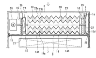
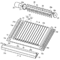
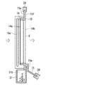
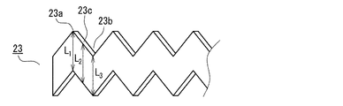
図1は、本発明の第1の実施例における空気調和機の断面図、図2は、同空気調和機のフィルター体と除塵体の取付け状態を示す横断面図、図3は、同フィルター体と除塵体の取付け構成を示す図、図4は、図3のA−A断面図、図5は、同除塵体の清掃体の斜視図である。 FIG. 1 is a cross-sectional view of an air conditioner according to a first embodiment of the present invention, FIG. 2 is a cross-sectional view showing a mounting state of a filter body and a dust removing body of the air conditioner, and FIG. FIG. 4 is a cross-sectional view taken along the line AA of FIG. 3, and FIG. 5 is a perspective view of the cleaning body of the dust removing body.
図1〜5において、1は、室内の壁2に取り付けられた本体ケースで、上方に室内の塵埃を含んだ外気を吸引するための吸込み口3を、下方に清浄空気を室内に排出する排気口4を、それぞれ有していて、吸込み口3と排気口4とを連通する通風路5が形成されている。
1 to 5, reference numeral 1 denotes a main body case attached to a
前記通風路5には、上流から下流に向かい、通過する塵埃を捕獲するフィルター体6と、冷気や暖気を供給する熱交換器7と、室内空気を吸込み口3から吸引し、熱交換器7を通して、熱交換器7で熱交換された空気を排気口4から排出するための送風機8が収納されている。
In the ventilation path 5, a
さらに、本体ケース1内には、送風機8の回転数や、前記熱交換器7の冷気や暖気のエネルギーをそれぞれ制御する制御体9が、制御室10に収納されている。
Further, in the main body case 1, a
また、本体ケース1の一部には、フィルター体6で捕獲された塵埃を廃棄処理等するための開閉蓋11が設けられている。フィルター体6は、多数の細孔を有する薄いシート状の素材を、山部14aと谷部14b及び傾斜部14cよりなる横断面が櫛刃状に形成されたフィルター14と、該フィルター14の外周囲を保持する枠体15より構成されている。本実施例では、フィルター14は、その谷部14bが、枠体15の上流面15aより上流側に位置するよう、枠体15に固着されている。
In addition, an opening /
枠体15の上流面15aには、フィルター14の左・右端のそれぞれに対向して、一対のガイド16が上流側に向けて、かつ、枠体15の上端15bから下端15c間に立設して形成され、そのガイド16には、後述する除塵体19の軸体20の両端を移動自在に支持する長軸受16aが形成されている。
A pair of
さらに、枠体15の上流面15aには、左側のガイド16の内側に位置するとともに、該ガイド16に並行して形成されギア21aを有するギア受け壁21と、右側のガイド16の外側に位置するとともに、該ガイド16に並行して、後述する除塵体19のローラー22に移動自在に嵌合するローラー受け溝下15dが形成されている。
Further, on the
15eは、枠体15の裏面、すなわち下流面15fに、下流側に突出するように形成された一対の突起である。
19は、フィルター体6のフィルター14で捕集された塵埃を除去し、フィルター14を新鮮にして、外気をスムーズに通過させるための除塵体であり、軸体20と、軟質材よりなるシート状の清掃体23から構成され、軸体20は、放射状で横長に延在し先端側がフィルター14の断面形状と同形の櫛刃状に形成され、清掃体23が取り付けられる清掃体取付部20aと、両端に設けられ、一対のガイド16の長軸受け16aに移動自在に保持される軸部20bを備えている。また、清掃体23の上端と下端は、それぞれフィルター14及び清掃体取付け部20bと同形の櫛刃状に形成されている。
これにより、清掃体23に形成された各山部23aから谷部23bおよび傾斜部23cも含め、清掃体23の各部における長さは全て同一となり(L1=L2=L3)、フィルター14に接触する接触圧も均一となり、除塵効果も、フィルター14の山部14a、谷部14bも傾斜部14cも全て取り残しなく均一になるものである。
As a result, the length of each part of the cleaning
26は、モーターなどからなり、除塵体19を枠体15の上端15bから下端15cまで移動させるための第1の駆動手段となる駆動体で、軸体20の一端に連結されている。27は、軸体20の軸部20bに固着または嵌合されると共に、ギア受け壁21のギア21aに噛み合い、駆動体26の回転を、所定の回転に制御すなわち除塵体19の回転を制御するための回転駆動ギアである。
22は、軸体20の、駆動体26と反対側の軸部20bの端部に回転自在に取着されたローラーで、ローラー22の上下左右は、枠体15に設けたローラー受溝(下)15dと、本体ケース1に設けたローラ受溝(上)1aとで回転自在に支持され、除塵体19や駆動体26が正規の位置間をぶれなく移動できるようにするための役目を果すものである。
28は、本体ケース1に形成され、枠体15の外周囲を保持する枠体支持部、29は、左右のガイド16の上部を保持するガイド支持体で、本体ケース1の一部に形成されている。31は、除塵体19によって除塵された塵埃を受け、収納する塵埃ボックスで、枠体15の下流面15fの下部に設けた突起15eと着脱自在に嵌合する突起嵌合穴31aと、塵埃を受け、収納する収納部31bより構成されている。
除塵体19の下降により、フィルター14から除塵された塵埃が、収納部31bに収納され、溜まった塵埃を廃棄処理するときは、本体ケース1の前面に設けた開閉蓋11を開け、収納部31bを、枠体15から取り外して簡単に処理することができる。
The dust removed from the
以上のように構成された本実施例における空気調和機の動作、作用は、以下の通りである。 The operation and action of the air conditioner in the present embodiment configured as described above are as follows.
リモコン(図示せず)で、冷房又は暖房のいずれかを選択し、希望の温度や風の強さを設定した後、操作スイッチ(図示せず)をONすると、制御体9により、送風機8や圧縮機(図示せず)の運転が開始し、室内の外気は、吸込み口3から流入し、フィルター体6を通過するが、この時、外気に含まれた塵埃が捕獲される。フィルター体6により清浄化された外気は、熱交換器7で熱交換されて、所定の温度乃至湿度になり、送風機8を通過して、排気口4より室内に放出される。
After selecting either cooling or heating with a remote controller (not shown), setting a desired temperature and wind strength, and turning on an operation switch (not shown), the
所定時間の冷房又は暖房運転が終了すると、制御体9により、駆動体26が運転を開始し、除塵体19が回転しながら下降し、この間に、フィルター14の上流面に捕獲された塵埃を下方に移動させ、塵埃ボックス31に収納させる。除塵体19が、所定の位置、例えば、フィルター14の下端まで下降すると、駆動体26が逆転し、除塵体19を上方に移動し、所定の位置、例えば、フィルター14の上端で停止する。この結果、フィルター14に付着していた塵埃がキレイに除去され、塵埃が残っていないために、外気は、再びフィルター14をスムーズに通過するようになって、送風機8には負荷がかからず、振動や騒音も軽減されることになる。
When the cooling or heating operation for a predetermined time is completed, the
又、本実施例では、断面が山部14aや谷部14b及び傾斜部14cを有する櫛刃状に形成されたフィルター14と清掃体23が、略同一形状で、かつ、清掃体23の各、谷部23bと山部23a及び傾斜部23c間のそれぞれにおいて全長が同一に形成されているので、フィルター14と清掃体23の接触力は全ての箇所で同一になり、フィルター14に捕獲された塵埃は、その全面においてムラなく清掃体23により剥離、除去される。
Further, in the present embodiment, the
なお、塵埃ボックス31に塵埃が所定量収納されたら、本体ケース1に設けた開閉蓋11を開け、塵埃ボックス31を、枠体15から取り外し、廃棄処理すればよい。
When a predetermined amount of dust is stored in the
尚、塵埃ボックス31に、塵埃量を検知する塵埃センサー等を設け、塵埃が所定量に達したときに、それを使用者に、LEDなどの表示手段(図示せず)や、ブザーなどの報知手段(図示せず)を介して報知すれば、塵埃処理がより便利になることは言うまでもないことである。
The
(実施例2) (Example 2)
図6は、本発明の第2の実施例における空気調和機のフィルター体と除塵体との構成を示す断面図、図7は、同空気調和機の除塵体の分解斜視図である。尚、上記第1の実施例における空気調和機と同一部分については、同一符号を付与し、それらの説明を省略する。 FIG. 6 is a cross-sectional view showing the configuration of the filter body and the dust remover of the air conditioner according to the second embodiment of the present invention, and FIG. 7 is an exploded perspective view of the dust remover of the air conditioner. In addition, about the same part as the air conditioner in the said 1st Example, the same code | symbol is provided and those description is abbreviate | omitted.
本実施例における空気調和機では、フィルター14の山部14aにフラット面として山部ストレート部14dが、谷部14bに、同じくフラット面として谷部ストレート部14eがそれぞれ形成され、更に、清掃体23のフィルター14との接触部についても、谷部23b、山部23aのそれぞれに、フラットな清掃体谷部ストレート部23dと清掃体山部ストレート部23eが形成されている。
In the air conditioner of the present embodiment, a peak
本実施例における清掃体23が取り付けられる軸体20の清掃体取付部20aは、図7に示すように、外観が円筒状で、外表面が櫛刃状に形成され、軸方向に、清掃体23を、取り付けるための複数の清掃体保持溝20cが、同じく櫛刃状に形成されている。
As shown in FIG. 7, the cleaning
これにより、フィルター14の山部14aや谷部14bに鋭利な傾斜面が形成されないために、特に、塵埃は、フィルター14のフラットな谷部ストレート部14eに堆積するので、除去しやすいものである。なお、清掃体23の清掃体谷部ストレート部23dと清掃体山部ストレート部23eの部分での根元から先端までの長さは、同一のために、フィルター14との接触力も同一になり、常に、均一な清掃性能が得られるものである。
Thereby, since a sharp inclined surface is not formed in the
(実施例3) (Example 3)
図8は、本発明の第3の実施例における空気調和機の除塵体の分解斜視図である。尚、上記実施例における空気調和機と同一部分については、同一符号を付与し、それらの説明を省略する。 FIG. 8 is an exploded perspective view of the dust remover of the air conditioner according to the third embodiment of the present invention. In addition, about the same part as the air conditioner in the said Example, the same code | symbol is provided and those description is abbreviate | omitted.
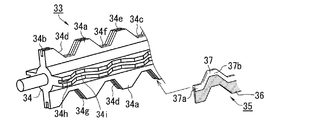
図8において、本実施例における空気調和機の除塵体33は、外周長手方向に、且つ放射状のリブ34aが複数形成された軸体34と、リブ34aに固着される清掃体35から構成され、リブ34aの形状は、山部34bと谷部34c及び傾斜部34dを有した断面が櫛刃状で、山部34bと谷部34cは、それぞれ、山部ストレート部34eと谷部ストレート部34fが設けられている。さらに、リブ34aには、該リブ34aと同形状の山部34hや谷部34iを有するブラシ保持溝34gが設けられている。
In FIG. 8, the
清掃体35は、全長が同一の多数の細径の棒状ブラシより成るブラシ体36と、ブラシ体36の根元を保持するとともに、ブラシ保持溝34gに、挿入固定されるブラシ保持体37より構成され、ブラシ保持体37も、保持体山部ストレート部37aや保持体谷部ストレート部37bが形成されている。
The cleaning
以上のように、本実施例によれば、軸体34に清掃体35を取り付けるときは、リブ34aに設けたブラシ保持溝34gに、清掃体35のブラシ保持体37を挿入し、固定するだけで良いので、除塵体33の製造、組み立てが容易になり、安価に提供することが出来る。
As described above, according to the present embodiment, when the cleaning
(実施例4) (Example 4)
図9は、本発明の第4の実施例における空気調和機の除塵体とフィルター体の関係を示す断面図、図10は、同除塵体の分解斜視図である。尚、上記実施例における空気調和機と同一部分については、同一符号を付与し、それらの説明を省略する。 FIG. 9 is a cross-sectional view showing the relationship between the dust remover and the filter body of the air conditioner in the fourth embodiment of the present invention, and FIG. 10 is an exploded perspective view of the dust remover. In addition, about the same part as the air conditioner in the said Example, the same code | symbol is provided and those description is abbreviate | omitted.
上記第1〜3の実施例では、フィルター体を所定の位置に固定し、除塵体をフィルター体の上流側の表面に沿って移動させるようにしたが、本実施例は、除塵体の取り付け位置を固定し、フィルター体を移動させるようにしたものである。 In the first to third embodiments, the filter body is fixed at a predetermined position, and the dust removing body is moved along the surface on the upstream side of the filter body. Is fixed and the filter body is moved.
図9、10において、39は、フィルター40と、フィルター40の外周を保持する枠体41からなるフィルター体で、枠体41の両端は、本体ケース1に設けたフィルター可動支持部1bにより移動自在に保持されると共に、枠体41の一側には、ギア受け41aが上下方向に延設されている。42は、フィルター体39を上下方向に駆動するモータなどからなる駆動体(第1の駆動手段)で、ギア受け41aと噛み合うとともに、駆動体42の動力を所定速度に制御するための減速ギア43と連結されている。
9 and 10,
44は、除塵体で、両端に、本体ケース1に設けた除塵体支持部38に回動自在に軸支される軸45aを有すると共に、一側に清掃体保持溝45bを有する軸体45と、端面が清掃体保持溝45bに挿入固着されるとともに、シート状の弾性部材から打ち抜いて形成された清掃体46から構成されている。清掃体保持溝45bの端面形状は、山部45cと谷部45d及び傾斜部45eを有した断面が櫛刃状で、山部45cと谷部45dは、それぞれ、山部ストレート部45fと谷部ストレート部45gが設けられている。清掃体保持溝45bの底部45hは、清掃体保持溝45bの端面と平行に形成されている。
更に、清掃体46の両端の形状は、清掃体保持溝45bの底部45hと同一形状で、しかも平行に形成されている。すなわち、清掃体46の、山部、谷部、傾斜部を問わず長手方向の各部での長さLが一定になるように形成されている。
Furthermore, the shape of the both ends of the cleaning
本実施例における空気調和機は、以上のように構成されているので、駆動体42が運転すると、断面が櫛刃状に形成されたフィルター40を有するフィルター体39が移動をし、その間に、端面が同じく櫛刃状に形成された除塵体44の清掃体46が、フィルター40から塵埃を強制剥離することが出来る。以上のように、フィルター体39を移動させるようにしても、除塵力を均一で、フィルター体39全体の塵埃除去効率の高い空気調和機を提供することが出来る。
Since the air conditioner in the present embodiment is configured as described above, when the driving
また、除塵体44を回転自在に構成したので、フィルター40と除塵体44の接触抵抗が軽減され、駆動体42の駆動力が小さく済むので、小型軽量化が可能となる。
Further, since the
尚、本実施例では、除塵体44を、本体ケース1に回動自在に設けたが、手動で回動する様にしても良い。
In the present embodiment, the
又、清掃体46を、シート状の材料から形成する代わりに、細径ブラシの集合体で形成しても良い。
Further, instead of forming the cleaning
以上のように、本発明にかかる空気調和機は、フィルター体のフィルターの全域に渡って除塵力を均一にして、フィルター体全体の塵埃除去効率が高いもので、各種空気調和機に利用できる。 As described above, the air conditioner according to the present invention makes the dust removal force uniform over the entire filter of the filter body and has high dust removal efficiency of the entire filter body, and can be used for various air conditioners.
1 本体ケース
3 吸込み口
4 排気口
5 通風路
6、39 フィルター体
8 送風機
14、40 フィルター
14a、23a、34b、34h、45c 山部
14b、23b、34c、34i、45d 谷部
14c、23c、34d、45e 傾斜部
15、41 枠体
19、33、44 除塵体
20、34、45 軸体
23、35、46 清掃体
23d 清掃体谷部ストレート部(フラット面)
23e 清掃体山部ストレート部(フラット面)
26、42 駆動体(第1の駆動手段)
34e、45f 山部ストレート部(フラット面)
34f、45g 谷部ストレート部(フラット面)
37a 保持体山部ストレート部(フラット面)
37b 保持体谷部ストレート部(フラット面)
DESCRIPTION OF SYMBOLS 1
14, 40
19, 33, 44
23e Cleaning body pile straight part (flat surface)
26, 42 Driving body (first driving means)
34e, 45f Mountain straight part (flat surface)
34f, 45g Valley straight part (flat surface)
37a Retainer mountain straight part (flat surface)
37b Retainer valley straight part (flat surface)
Claims (3)
Priority Applications (1)
| Application Number | Priority Date | Filing Date | Title |
|---|---|---|---|
| JP2008144071A JP2009287902A (en) | 2008-06-02 | 2008-06-02 | Air conditioner |
Applications Claiming Priority (1)
| Application Number | Priority Date | Filing Date | Title |
|---|---|---|---|
| JP2008144071A JP2009287902A (en) | 2008-06-02 | 2008-06-02 | Air conditioner |
Publications (2)
| Publication Number | Publication Date |
|---|---|
| JP2009287902A true JP2009287902A (en) | 2009-12-10 |
| JP2009287902A5 JP2009287902A5 (en) | 2011-07-14 |
Family
ID=41457280
Family Applications (1)
| Application Number | Title | Priority Date | Filing Date |
|---|---|---|---|
| JP2008144071A Pending JP2009287902A (en) | 2008-06-02 | 2008-06-02 | Air conditioner |
Country Status (1)
| Country | Link |
|---|---|
| JP (1) | JP2009287902A (en) |
Cited By (2)
| Publication number | Priority date | Publication date | Assignee | Title |
|---|---|---|---|---|
| JP2017067408A (en) * | 2015-09-30 | 2017-04-06 | ダイキン工業株式会社 | Air conditioner |
| CN111288601A (en) * | 2020-02-19 | 2020-06-16 | 郭曦 | Fresh air pipe for indoor design |
Citations (7)
| Publication number | Priority date | Publication date | Assignee | Title |
|---|---|---|---|---|
| JPS5739554U (en) * | 1980-08-19 | 1982-03-03 | ||
| JPH08303803A (en) * | 1995-05-08 | 1996-11-22 | Daikin Ind Ltd | Air conditioner |
| JPH11129695A (en) * | 1997-10-29 | 1999-05-18 | Shin Fukui | Motor operated blackboard eraser |
| JP2005021186A (en) * | 2003-06-30 | 2005-01-27 | Matsushita Electric Ind Co Ltd | Vacuum cleaner |
| JP2005034213A (en) * | 2003-07-16 | 2005-02-10 | Matsushita Electric Ind Co Ltd | Vacuum cleaner |
| JP2005261518A (en) * | 2004-03-17 | 2005-09-29 | Toshiba Tec Corp | Electric vacuum cleaner |
| JP2008002772A (en) * | 2006-06-23 | 2008-01-10 | Kowa Co Ltd | Air conditioner cleaning body, rotary rotor, and air conditioner |
-
2008
- 2008-06-02 JP JP2008144071A patent/JP2009287902A/en active Pending
Patent Citations (7)
| Publication number | Priority date | Publication date | Assignee | Title |
|---|---|---|---|---|
| JPS5739554U (en) * | 1980-08-19 | 1982-03-03 | ||
| JPH08303803A (en) * | 1995-05-08 | 1996-11-22 | Daikin Ind Ltd | Air conditioner |
| JPH11129695A (en) * | 1997-10-29 | 1999-05-18 | Shin Fukui | Motor operated blackboard eraser |
| JP2005021186A (en) * | 2003-06-30 | 2005-01-27 | Matsushita Electric Ind Co Ltd | Vacuum cleaner |
| JP2005034213A (en) * | 2003-07-16 | 2005-02-10 | Matsushita Electric Ind Co Ltd | Vacuum cleaner |
| JP2005261518A (en) * | 2004-03-17 | 2005-09-29 | Toshiba Tec Corp | Electric vacuum cleaner |
| JP2008002772A (en) * | 2006-06-23 | 2008-01-10 | Kowa Co Ltd | Air conditioner cleaning body, rotary rotor, and air conditioner |
Cited By (2)
| Publication number | Priority date | Publication date | Assignee | Title |
|---|---|---|---|---|
| JP2017067408A (en) * | 2015-09-30 | 2017-04-06 | ダイキン工業株式会社 | Air conditioner |
| CN111288601A (en) * | 2020-02-19 | 2020-06-16 | 郭曦 | Fresh air pipe for indoor design |
Similar Documents
| Publication | Publication Date | Title |
|---|---|---|
| CN209173592U (en) | Filter screen cleaning module and air processor | |
| JP2004044933A (en) | Air conditioner | |
| JP2006071121A (en) | Air conditioner | |
| JP7289039B2 (en) | Air conditioner provided with filter cleaning device and air filter cleaning method for air conditioner | |
| JP4040433B2 (en) | Air conditioner indoor unit | |
| JP2010032065A (en) | Filter cleaning device, air conditioner | |
| JP2008173616A (en) | Cleaning tool and air conditioner | |
| JP4781956B2 (en) | Air conditioner cleaning device and air conditioner | |
| JP6089301B2 (en) | Air conditioner | |
| JP4896636B2 (en) | Air conditioner cleaning device and air conditioner | |
| JP6152617B2 (en) | Air conditioner | |
| JP2007263412A (en) | Air conditioner cleaning device and air conditioner | |
| JP2009287902A (en) | Air conditioner | |
| JP2008029912A (en) | Cleaning device for filter | |
| JP4269141B2 (en) | Air conditioner | |
| JP2010002070A (en) | Air conditioner | |
| JP2009180465A (en) | Air conditioner | |
| JP2009257735A (en) | Air conditioner | |
| JP2008039324A (en) | Air conditioner indoor unit | |
| JP4911137B2 (en) | Air conditioner | |
| JP4125340B2 (en) | Air conditioner cleaning device and air conditioner | |
| CN117646937A (en) | Self-cleaning structure and control method of air conditioner filter screen and air conditioner | |
| JP2008002772A (en) | Air conditioner cleaning body, rotary rotor, and air conditioner | |
| JP2009264618A (en) | Air conditioner | |
| JP2010121881A (en) | Air conditioner |
Legal Events
| Date | Code | Title | Description |
|---|---|---|---|
| A521 | Written amendment |
Free format text: JAPANESE INTERMEDIATE CODE: A523 Effective date: 20110528 |
|
| A621 | Written request for application examination |
Free format text: JAPANESE INTERMEDIATE CODE: A621 Effective date: 20110528 |
|
| RD02 | Notification of acceptance of power of attorney |
Free format text: JAPANESE INTERMEDIATE CODE: A7422 Effective date: 20110528 |
|
| A977 | Report on retrieval |
Free format text: JAPANESE INTERMEDIATE CODE: A971007 Effective date: 20120829 |
|
| A131 | Notification of reasons for refusal |
Free format text: JAPANESE INTERMEDIATE CODE: A131 Effective date: 20120907 |
|
| A02 | Decision of refusal |
Free format text: JAPANESE INTERMEDIATE CODE: A02 Effective date: 20130108 |