JP2009292017A - Delivery controlling device and delivery controlling method - Google Patents
Delivery controlling device and delivery controlling method Download PDFInfo
- Publication number
- JP2009292017A JP2009292017A JP2008147222A JP2008147222A JP2009292017A JP 2009292017 A JP2009292017 A JP 2009292017A JP 2008147222 A JP2008147222 A JP 2008147222A JP 2008147222 A JP2008147222 A JP 2008147222A JP 2009292017 A JP2009292017 A JP 2009292017A
- Authority
- JP
- Japan
- Prior art keywords
- ink
- ejection
- delay time
- reference position
- detection
- Prior art date
- Legal status (The legal status is an assumption and is not a legal conclusion. Google has not performed a legal analysis and makes no representation as to the accuracy of the status listed.)
- Granted
Links
Images


Landscapes
- Ink Jet (AREA)
- Character Spaces And Line Spaces In Printers (AREA)
Abstract
【課題】主走査方向における画質を向上させることができる。
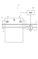
【解決手段】インクジェットプリンタ1には、所定間隔で基準マークが付されたリニアスケール5と、主走査方向Aに移動可能でインクを吐出するヘッドユニット7と、インクの吐出制御を行う制御部10とが設けられており、ヘッドユニット7には、インクを吐出するインクジェットヘッド8と、リニアスケール5に付された基準マークを検出するリニアエンコーダ9とが設けられている。そして、ヘッドユニット7の移動によりリニアエンコーダ9が基準マークを検出すると、制御部10は、基準マークの検出タイミングからの遅延時間を変動させて、インクを吐出する吐出タイミングを決定し、インクジェットヘッド8からインクを吐出させる。これにより、メディア3に着弾したインクのドットのずれを視覚的に目立たなくすることができる。
【選択図】図1The image quality in the main scanning direction can be improved.
An ink jet printer includes a linear scale with reference marks at predetermined intervals, a head unit that can move in a main scanning direction and eject ink, and a control unit that performs ink ejection control. The head unit 7 is provided with an ink jet head 8 that ejects ink and a linear encoder 9 that detects a reference mark attached to the linear scale 5. When the linear encoder 9 detects the reference mark due to the movement of the head unit 7, the control unit 10 varies the delay time from the reference mark detection timing, determines the ejection timing for ejecting ink, and the inkjet head 8. Ink is discharged from Thereby, the deviation of the ink dots landed on the medium 3 can be made visually inconspicuous.
[Selection] Figure 1
Description
本発明は、インクジェットヘッドからインクを吐出するインクジェットプリンタの吐出制御装置及び吐出制御方法に関する。 The present invention relates to an ejection control device and an ejection control method for an inkjet printer that ejects ink from an inkjet head.
一般に、インクジェットプリンタは、インクを吐出するインクジェットヘッドを主走査方向に往復移動させて、プラテンに載置されたメディアに1ライン分の印刷を行い、その後、主走査方向に対して直交する搬送方向(副走査方向)にメディアを1ライン分搬送する。そして、このインクジェットヘッドの移動による印刷とメディアの搬送とを繰返すことで、メディア全体の印刷を行っている。 In general, an ink jet printer reciprocates an ink jet head for ejecting ink in a main scanning direction to perform printing for one line on a medium placed on a platen, and then a conveyance direction orthogonal to the main scanning direction. The media is conveyed by one line in the (sub-scanning direction). The entire medium is printed by repeating the printing by the movement of the inkjet head and the conveyance of the medium.
このインクジェットプリンタには、主走査方向に延びるリニアスケールが固定されている。リニアスケールは、主走査方向における位置を示すために、所定間隔で基準マークが付されている。一方、主走査方向に移動するインクジェットヘッドには、リニアスケールを検出するリニアエンコーダが取り付けられている。そして、リニアエンコーダによりリニアスケールの基準マークを検出することで、主走査方向におけるインクジェットヘッドの位置を把握することが可能となっている(例えば、特許文献1参照)。 In this ink jet printer, a linear scale extending in the main scanning direction is fixed. The linear scale is provided with reference marks at predetermined intervals in order to indicate positions in the main scanning direction. On the other hand, a linear encoder that detects a linear scale is attached to the inkjet head that moves in the main scanning direction. The position of the inkjet head in the main scanning direction can be grasped by detecting the reference mark of the linear scale with a linear encoder (see, for example, Patent Document 1).
ところが、リニアエンコーダの位置とインクを吐出する吐出ノズルの位置との位置関係や、インクの吐出制御などに要する処理時間のため、リニアエンコーダで基準マークを検出してからインクジェットヘッドからインクを吐出するまでの間には、所定の遅延時間が発生する。 However, because of the positional relationship between the position of the linear encoder and the position of the discharge nozzle that discharges ink and the processing time required for ink discharge control, the ink is discharged from the inkjet head after the reference mark is detected by the linear encoder. In the meantime, a predetermined delay time occurs.
そこで、従来の吐出制御装置では、インクジェットヘッドが主走査方向に走査する際に、リニアエンコーダがリニアスケールの基準マークを検出すると、所定の遅延時間が経過したタイミングを、インクの吐出タイミングとして決定していた。
しかしながら、実際には、インクジェットヘッドを移動させるモータの振動などによって、インクジェットヘッドの移動速度が僅かに変動する。このため、従来の吐出制御装置では、基準マークを検出してからインクを吐出するまでの時間が変動することにより、メディアに着弾されたインクのドット間隔が局部的に変動し、印刷された画像にバンディングなどの印刷縞が発生するという問題があった。 In practice, however, the moving speed of the ink jet head slightly varies due to vibrations of a motor that moves the ink jet head. For this reason, in the conventional ejection control device, the time between the detection of the reference mark and the ejection of the ink varies, so that the dot interval of the ink landed on the media varies locally, and the printed image There was a problem that printing stripes such as banding occurred.
また、実際には、インクジェットヘッドのノズル径の誤差や、インクの温度、周囲の温度、印刷されるメディアの種類などによって、メディアに着弾したインクのドット径が変動する。このため、インクジェットヘッドの移動速度が一定であったとしても、局部的にドット径が小さくなると、印刷画像が局部的に薄くなって、バンディングなどの印刷縞が発生するという問題があった。 In practice, the dot diameter of ink landed on the medium varies depending on the nozzle diameter error of the inkjet head, the temperature of the ink, the ambient temperature, the type of the medium to be printed, and the like. For this reason, even if the moving speed of the inkjet head is constant, there is a problem that when the dot diameter is locally reduced, the printed image is locally thinned and print stripes such as banding occur.
そこで、本発明は、主走査方向における画質を向上させることができる吐出制御装置及び吐出制御方法を提供することを目的とする。 SUMMARY An advantage of some aspects of the invention is that it provides a discharge control apparatus and a discharge control method that can improve image quality in the main scanning direction.
本発明に係る吐出制御装置は、インクジェットヘッドからインクを吐出するインクジェットプリンタの吐出制御装置であって、インクを吐出させるための基準位置を検出する基準位置検出手段と、基準位置検出手段により基準位置を検出すると、基準位置を検出してからインクを吐出するまでの遅延時間を基準位置の検出ごとに変動させて、インクの吐出タイミングを決定する吐出タイミング決定手段と、を有することを特徴とする。 An ejection control apparatus according to the present invention is an ejection control apparatus for an inkjet printer that ejects ink from an inkjet head, and includes a reference position detection unit that detects a reference position for ejecting ink, and a reference position by the reference position detection unit. And a discharge timing determining means for determining the ink discharge timing by varying the delay time from the detection of the reference position to the discharge of ink every time the reference position is detected. .
本発明に係る吐出制御装置によれば、基準位置検出手段が基準位置を検出すると、吐出タイミング決定手段が、この基準位置を検出してからインクを吐出するまでの遅延時間を基準位置の検出ごとに変動させて、インクの吐出タイミングを決定する。すなわち、吐出タイミング決定手段は、基準位置が検出されるたびに、基準位置を検出してからインクを吐出するまでの遅延時間が一定時間ではなくなるように(不均一となるように)、吐出タイミングを決定する。このように、遅延時間を意図的に変動させて吐出タイミングを決定することで、主走査方向において、メディアに着弾したインクのドット間隔が全体的に不均一となり、局部的にドット間隔が不均一となるのを防止することができるため、メディアに着弾したインクのドット間隔のずれを視覚的に目立たなくすることができる。これにより、局部的なドット間隔のずれに起因するバンディングなどの印刷縞の発生を防止することができ、主走査方向における画質を向上させることができる。特に、ベタ塗りのように一様な塗りつぶし印刷を行う場合は、バンディングなどの印刷縞が目立ちやすいため、特に効果的である。 According to the ejection control device of the present invention, when the reference position detection unit detects the reference position, the ejection timing determination unit calculates the delay time from the detection of the reference position to the ejection of ink every time the reference position is detected. To determine the ink ejection timing. In other words, each time the reference position is detected, the discharge timing determination unit discharges the discharge timing so that the delay time from the detection of the reference position to the discharge of ink is not a fixed time (not uniform). To decide. In this way, by determining the ejection timing by intentionally changing the delay time, the dot interval of the ink that has landed on the medium becomes non-uniform in the main scanning direction, and the dot interval is locally non-uniform. Therefore, the deviation of the dot interval of the ink landed on the medium can be made visually inconspicuous. As a result, it is possible to prevent the occurrence of printing stripes such as banding due to a local dot interval shift, and to improve the image quality in the main scanning direction. In particular, when performing solid fill printing such as solid coating, print fringes such as banding tend to be noticeable, which is particularly effective.
この場合、吐出タイミング決定手段は、遅延時間を、乱数値により変動させることが好ましい。この吐出制御装置によれば、乱数値に基づいて遅延時間を変動させるため、遅延時間を不規則に変動させることができる。このため、メディアに着弾したインクのドット間隔を不規則に変動させることができる。 In this case, it is preferable that the ejection timing determination unit varies the delay time according to a random number value. According to this discharge control apparatus, since the delay time is changed based on the random number value, the delay time can be changed irregularly. For this reason, the dot interval of the ink landed on the medium can be irregularly changed.
一方、吐出タイミング決定手段は、遅延時間を、所定周波数の波状に変動させることが好ましい。この吐出制御装置によれば、所定周波数の波状に遅延時間を変動させることができるため、メディアに着弾したインクのドット間隔を変動させることができるとともに、この周波数を調整することで、このドット間隔を調整することができる。 On the other hand, it is preferable that the discharge timing determining means varies the delay time in a wave shape having a predetermined frequency. According to this ejection control device, the delay time can be varied in a wave shape with a predetermined frequency, so that the dot interval of ink landed on the medium can be varied, and this dot interval can be adjusted by adjusting this frequency. Can be adjusted.
また、吐出タイミング決定手段は、インクジェットヘッドの移動速度に応じて、遅延時間の変動幅を調節することが好ましい。この吐出制御装置によれば、吐出タイミング決定手段が、インクジェットヘッドの移動速度に応じて遅延時間の変動幅を調節する。すなわち、インクジェットヘッドの移動速度が高くなるとメディアに着弾するインクのドット間隔が広がり、インクジェットヘッドの移動速度が低くなるとメディアに着弾するインクのドット間隔が狭くなる。このため、遅延時間の変動幅を、インクジェットヘッドの移動速度に応じて調節することで、メディアに着弾するインクのドット間隔に応じた適切な吐出タイミングを得ることができる。例えば、画質よりもスループットを優先させるためにインクジェットヘッドの移動速度を速くする場合は、メディアに着弾するインクのドット間隔が広くなるため、遅延時間の変動幅を大きくして吐出タイミングを決定することで、ドット間隔のずれをより効果的に目立たなくさせることができる。一方、スループットよりも画質を優先させるためにインクジェットヘッドの移動速度を遅くする場合は、メディアに着弾するインクのドット間隔が狭くなるため、遅延時間の変動幅を小さくして吐出タイミングを決定することで、ドット間隔のずれを目立たなくさせ、かつ、高精細な印刷を可能とすることができる。 In addition, it is preferable that the ejection timing determination unit adjusts the fluctuation range of the delay time according to the moving speed of the inkjet head. According to this discharge control apparatus, the discharge timing determination means adjusts the fluctuation range of the delay time according to the moving speed of the inkjet head. That is, when the moving speed of the ink jet head increases, the dot interval of ink that lands on the medium increases, and when the moving speed of the ink jet head decreases, the dot interval of the ink that lands on the medium decreases. For this reason, by adjusting the fluctuation range of the delay time according to the moving speed of the inkjet head, it is possible to obtain an appropriate ejection timing according to the dot interval of the ink that lands on the medium. For example, when increasing the moving speed of the inkjet head in order to prioritize throughput over image quality, the dot interval of the ink that lands on the media becomes wider, so the variation range of the delay time should be increased to determine the ejection timing Thus, it is possible to make the deviation of the dot interval more inconspicuous. On the other hand, if the moving speed of the inkjet head is slowed down in order to prioritize image quality over throughput, the interval between the ink dots that land on the media will be narrowed, so the variation range of the delay time should be reduced to determine the ejection timing. Thus, it is possible to make the dot interval shift inconspicuous and enable high-definition printing.
また、吐出タイミング決定手段は、インクの温度、周囲の温度及び印刷されるメディアの種類の少なくとも1つに応じて、遅延時間の変動幅を調節することが好ましい。この吐出制御装置によれば、吐出タイミング決定手段が、インクの温度、周囲の温度及び印刷されるメディアの種類の少なくとも1つに応じて遅延時間の変動幅を調節する。すなわち、メディアに着弾するインクのドット径は、インクの温度、周囲の温度及び印刷されるメディアの種類によって変動する。このため、遅延時間の変動幅を、インクの温度、周囲の温度及び印刷されるメディアの種類の少なくとも1つに応じて調節することで、メディアに着弾するインクのドット径に応じた適切な吐出タイミングを得ることができる。例えば、メディアに着弾するインクのドット径が大きい場合は、ドット間隔が狭くなり、局部的なドット間隔のずれが目立ち難いため、遅延時間の変動幅を狭くすることで、高精細な印刷を可能とすることができる。一方、メディアに着弾するインクのドット径が小さい場合は、ドット間隔が広くなり、局部的なドット間隔のずれが目立ちやすいため、遅延時間の変動幅を広くすることで、バンディングの発生を効果的に抑制することができる。 In addition, it is preferable that the ejection timing determination unit adjusts the fluctuation range of the delay time according to at least one of the ink temperature, the ambient temperature, and the type of the medium to be printed. According to this discharge control apparatus, the discharge timing determination unit adjusts the fluctuation range of the delay time according to at least one of the ink temperature, the ambient temperature, and the type of the medium to be printed. That is, the dot diameter of the ink that lands on the medium varies depending on the temperature of the ink, the ambient temperature, and the type of the medium to be printed. For this reason, by adjusting the fluctuation range of the delay time according to at least one of the temperature of the ink, the ambient temperature, and the type of the medium to be printed, an appropriate ejection corresponding to the dot diameter of the ink that lands on the medium. Timing can be obtained. For example, if the dot diameter of the ink that lands on the media is large, the dot interval becomes narrow, and the local dot interval shift is less noticeable, so high-definition printing is possible by narrowing the fluctuation range of the delay time It can be. On the other hand, when the dot diameter of the ink that lands on the media is small, the dot interval becomes wide, and the deviation of the local dot interval tends to be conspicuous. Can be suppressed.
そして、インクジェットヘッドから吐出されるインクが、紫外線の照射により硬化する紫外線硬化型インクであって、吐出タイミング決定手段は、インクジェットヘッドから吐出された紫外線硬化型インクに照射する紫外線の光量に応じて、遅延時間の変動幅を調節することとしてもよい。 The ink ejected from the inkjet head is an ultraviolet curable ink that is cured by the irradiation of ultraviolet rays, and the ejection timing determining means is responsive to the amount of ultraviolet radiation that irradiates the ultraviolet curable ink ejected from the inkjet head. The fluctuation range of the delay time may be adjusted.
この吐出制御装置によれば、吐出タイミング決定手段が、インクジェットヘッドから吐出された紫外線硬化型インクに照射する紫外線の光量に応じて、遅延時間の変動幅を調節する。すなわち、紫外線硬化型インクは、紫外線の照射により硬化するため、紫外線の光量に応じて紫外線硬化型インクのドット径が変わる。このため、紫外線の光量に応じて遅延時間の変動幅を調整することで、紫外線硬化型インクのドット径に応じた適切な吐出タイミングを得ることができる。 According to this discharge control apparatus, the discharge timing determination unit adjusts the fluctuation range of the delay time according to the amount of ultraviolet light irradiated to the ultraviolet curable ink discharged from the inkjet head. That is, since the ultraviolet curable ink is cured by irradiation with ultraviolet rays, the dot diameter of the ultraviolet curable ink changes according to the amount of ultraviolet rays. For this reason, by adjusting the fluctuation range of the delay time according to the amount of ultraviolet light, it is possible to obtain an appropriate ejection timing according to the dot diameter of the ultraviolet curable ink.
本発明に係る吐出制御方法は、インクジェットヘッドからインクを吐出するインクジェットプリンタの吐出制御方法であって、インクを吐出させるための基準位置を検出する検出ステップと、検出ステップによる基準位置の検出に基づいて、インクを吐出する吐出タイミングを決定する吐出タイミング決定ステップと、を有し、吐出タイミング決定ステップは、基準位置を検出してからインクを吐出するまでの遅延時間を基準位置の検出ごとに変動させて、吐出タイミングを決定することを特徴とする。 An ejection control method according to the present invention is an ejection control method for an ink jet printer that ejects ink from an ink jet head, and includes a detection step for detecting a reference position for ejecting ink, and detection of a reference position by the detection step. An ejection timing determination step for determining an ejection timing for ejecting ink, and the ejection timing determination step varies a delay time from the detection of the reference position to the ejection of the ink every time the reference position is detected. Thus, the ejection timing is determined.
本発明に係る吐出制御方法によれば、検出ステップにより基準位置を検出すると、吐出タイミング決定ステップにより、この基準位置を検出してからインクを吐出するまでの遅延時間を基準位置の検出ごとに変動させて、インクの吐出タイミングを決定する。すなわち、吐出タイミング決定ステップは、基準位置が検出されるたびに、基準位置を検出してからインクを吐出するまでの遅延時間が一定時間ではなくなるように(不均一となるように)、吐出タイミングを決定する。このように、遅延時間を意図的に変動させて吐出タイミングを決定することで、主走査方向において、メディアに着弾したインクのドット間隔が全体的に不均一となり、局部的にドット間隔が不均一となるのを防止することができるため、メディアに着弾したインクのドット間隔のずれを視覚的に目立たなくすることができる。これにより、局部的なドット間隔のずれに起因するバンディングなどの印刷縞の発生を防止することができ、主走査方向における画質を向上させることができる。特に、ベタ塗りのように一様な塗りつぶし印刷を行う場合は、バンディングなどの印刷縞が目立ちやすいため、特に効果的である。 According to the ejection control method of the present invention, when the reference position is detected in the detection step, the delay time from the detection of the reference position to the ejection of ink is varied for each detection of the reference position in the ejection timing determination step. Thus, the ink ejection timing is determined. That is, every time the reference position is detected, the ejection timing determination step is performed so that the delay time from the detection of the reference position to the ejection of ink is not a fixed time (so as to be non-uniform). To decide. In this way, by determining the ejection timing by intentionally changing the delay time, the dot interval of the ink that has landed on the medium becomes non-uniform in the main scanning direction, and the dot interval is locally non-uniform. Therefore, the deviation of the dot interval of the ink landed on the medium can be made visually inconspicuous. As a result, it is possible to prevent the occurrence of printing stripes such as banding due to a local dot interval shift, and to improve the image quality in the main scanning direction. In particular, when performing solid fill printing such as solid coating, print fringes such as banding tend to be noticeable, which is particularly effective.
本発明に係る吐出制御プログラムは、インクジェットヘッドからインクを吐出するインクジェットプリンタに実行させるための吐出制御プログラムであって、インクを吐出させるための基準位置を検出する検出ステップと、前記検出ステップによる前記基準位置の検出に基づいて、インクを吐出する吐出タイミングを決定する吐出タイミング決定ステップと、を有し、前記吐出タイミング決定ステップは、前記基準位置を検出してから前記インクを吐出するまでの遅延時間を前記基準位置の検出ごとに変動させて、前記吐出タイミングを決定することを特徴とする。 An ejection control program according to the present invention is an ejection control program for causing an inkjet printer that ejects ink from an inkjet head to execute a detection step of detecting a reference position for ejecting ink, and the detection step An ejection timing determination step for determining an ejection timing for ejecting ink based on detection of a reference position, and the ejection timing determination step includes a delay from the detection of the reference position to the ejection of the ink. The ejection timing is determined by varying the time for each detection of the reference position.
本発明に係る吐出制御プログラムによれば、検出ステップにより基準位置を検出すると、吐出タイミング決定ステップにより、この基準位置を検出してからインクを吐出するまでの遅延時間を基準位置の検出ごとに変動させて、インクの吐出タイミングを決定する。すなわち、吐出タイミング決定ステップは、基準位置が検出されるたびに、基準位置を検出してからインクを吐出するまでの遅延時間が一定時間ではなくなるように(不均一となるように)、吐出タイミングを決定する。このように、遅延時間を意図的に変動させて吐出タイミングを決定することで、主走査方向において、メディアに着弾したインクのドット間隔が全体的に不均一となり、局部的にドット間隔が不均一となるのを防止することができるため、メディアに着弾したインクのドット間隔のずれを視覚的に目立たなくすることができる。これにより、局部的なドット間隔のずれに起因するバンディングなどの印刷縞の発生を防止することができ、主走査方向における画質を向上させることができる。特に、ベタ塗りのように一様な塗りつぶし印刷を行う場合は、バンディングなどの印刷縞が目立ちやすいため、特に効果的である。 According to the ejection control program according to the present invention, when the reference position is detected by the detection step, the delay time from the detection of the reference position to the ejection of the ink is changed every time the reference position is detected by the ejection timing determination step. Thus, the ink ejection timing is determined. That is, every time the reference position is detected, the ejection timing determination step is performed so that the delay time from the detection of the reference position to the ejection of ink is not a fixed time (so as to be non-uniform). To decide. In this way, by determining the ejection timing by intentionally changing the delay time, the dot interval of the ink that has landed on the medium becomes non-uniform in the main scanning direction, and the dot interval is locally non-uniform. Therefore, the deviation of the dot interval of the ink landed on the medium can be made visually inconspicuous. As a result, it is possible to prevent the occurrence of printing stripes such as banding due to a local dot interval shift, and to improve the image quality in the main scanning direction. In particular, when performing solid fill printing such as solid coating, print fringes such as banding tend to be noticeable, which is particularly effective.
本発明によれば、主走査方向における画質を向上させることができる。 According to the present invention, the image quality in the main scanning direction can be improved.
以下、図面を参照して、本発明に係る吐出制御装置及び吐出制御方法の好適な実施形態について詳細に説明する。なお、全図中、同一又は相当部分には同一符号を付すこととする。 DESCRIPTION OF EXEMPLARY EMBODIMENTS Hereinafter, preferred embodiments of a discharge control device and a discharge control method according to the present invention will be described in detail with reference to the drawings. In the drawings, the same or corresponding parts are denoted by the same reference numerals.
図1は、本実施形態に係るインクジェットプリンタの平面図、図2は、図1に示すインクジェットプリンタの部分拡大図である。図1及び図2に示すように、本実施形態のインクジェットプリンタ1は、プラテン2上に搬送されたメディア3に、カラー画像を印刷するインクジェット方式のプリンタである。
FIG. 1 is a plan view of an ink jet printer according to this embodiment, and FIG. 2 is a partially enlarged view of the ink jet printer shown in FIG. As shown in FIGS. 1 and 2, the
インクジェットプリンタ1には、プラテン2上に載置されたメディア3を搬送方向Bに搬送する搬送ローラ4が設けられている。この搬送ローラ4は、メディア3を、1ライン分のピッチで搬送方向Bに搬送する。
The
また、インクジェットプリンタ1には、プラテン2の上方(図1において手前側)において、メディア3の搬送方向Bと直交する主走査方向Aに掛け渡されるリニアスケール5が設けられている。リニアスケール5は、主走査方向Aに延びた長尺の板状に形成されている。そして、リニアスケール5には、所定間隔で基準マークMが付されている。基準マークMは、主走査方向Aにおける位置を示すためのものである。このため、基準マークMは、主走査方向Aにおける位置が分かれば如何なる間隔に付されていてもよい。
In addition, the
また、インクジェットプリンタ1には、プラテン2の上方において、主走査方向Aに掛け渡されるガイドレール6が設けられている。ガイドレール6は、主走査方向Aに延びた長尺の板状に形成されており、リニアスケール5と平行に配置されている。そして、ガイドレール6には、インクを吐出するインクジェットヘッド8が搭載されたヘッドユニット7が、ガイドレール6の延在方向において移動可能に保持されている。
The
ヘッドユニット7には、インクジェットヘッド8と、リニアエンコーダ9とが設けられている。そして、ヘッドユニット7は、図示しない駆動部により、走査方向A(図1及び図2において左方向)及び主走査方向Aの逆方向(図1及び図2において右方向)に移動可能となっている。ヘッドユニット7の移動は、例えば、ヘッドユニット7に連結された搬送ベルトをモータ等で回転させることで実現される。なお、ガイドレール6の主走査方向A後方端部(図1及び図2において右端部)が、ヘッドユニット7の待機位置となる。
The
インクジェットヘッド8は、インクを吐出して、メディア3に画像を印刷するものである。図では、1色のインクを吐出するインクジェットヘッド8しか示していないが、実際には、イエローY、マゼンダM、シアンC及びブラックKの各インクを吐出するインクジェットヘッドそれぞれが設けられている。インクジェットヘッド8には、インクを貯留するインクタンク(不図示)が連結されている。そして、このインクタンクからインクが供給されることで、インクジェットヘッド8からインクが吐出可能となる。
The
リニアエンコーダ9は、リニアスケール5に付された基準マークMを検出する検出器である。リニアエンコーダ9は、この基準マークMを検出すると、エンコーダ信号を送信する。なお、ヘッドユニット7とリニアスケール5とは、平行に配置されているため、リニアエンコーダ9が基準マークMを検出することで、主走査方向Aに移動するヘッドユニット7の主走査方向Aにおける位置が把握できるようになっている。
The
そして、インクジェットプリンタ1には、搬送ローラ4、ヘッドユニット7、インクジェットヘッド8を制御する制御部10が設けられている。
The
制御部10は、搬送ローラ4、ヘッドユニット7、インクジェットヘッド8、リニアエンコーダ9と接続されている。そして、制御部10は、搬送ローラ4、ヘッドユニット7、インクジェットヘッド8等に電気信号を送信することで、搬送ローラ4、ヘッドユニット7、インクジェットヘッド8等を制御するものである。
The
図3は、制御部の機能構成例を示した図である。図3に示すように、制御部10は、メディア搬送制御部11、ヘッドユニット移動制御部12、吐出制御部13、基準マーク検出部14及び吐出タイミング決定部15として機能する。なお、制御部10は、例えば、CPU、ROM、RAMを含むコンピュータを主体として構成されている。そして、図3において説明した各機能は、CPUやRAM上に所定のコンピュータソフトウェアを読み込ませ、CPUの制御のもとで動作させることで実現される。
FIG. 3 is a diagram illustrating a functional configuration example of the control unit. As shown in FIG. 3, the
メディア搬送制御部11は、搬送ローラ4の駆動制御を行い、プラテン2上に載置されたメディア3を、1走査毎に1ライン分のピッチで搬送方向Bに搬送させる。
The media
ヘッドユニット移動制御部12は、ヘッドユニット7の駆動制御を行い、ヘッドユニット7を所定の速度で主走査方向A及び主走査方向Aの逆方向に移動させる。
The head unit
吐出制御部13は、インクジェットヘッド8の吐出制御を行い、インクジェットヘッド8からインクを吐出させる。
The
基準マーク検出部14は、リニアエンコーダ9から送信されるエンコーダ信号を検出する。すなわち、基準マーク検出部14は、このエンコーダ信号を検出することで、リニアエンコーダ9が基準マークMを検出したタイミングを認識する。
The reference
吐出タイミング決定部15は、吐出制御部13においてインクジェットヘッド8の吐出制御を行うために、インクジェットヘッド8からインクを吐出する吐出タイミングを決定する。つまり、吐出タイミング決定部15は、基準マーク検出部14におけるエンコーダ信号の検出タイミングに基づいて、インクの吐出タイミングを決定する。
The ejection
図4は、エンコーダ信号と吐出タイミングとの関係を示した図であり、(a)はリニアスケール、(b)はエンコーダ信号、(c)は遅延時間及び吐出タイミングをそれぞれ示している。図4に示すように、リニアエンコーダ9が基準マークMを検出してエンコーダ信号を送信すると、基準マーク検出部14がこのエンコーダ信号を検出する。そして、吐出タイミング決定部15は、基準マーク検出部14がエンコーダ信号を検出してからインクを吐出するまでの遅延時間tを算出し、吐出タイミングQを決定する。
FIG. 4 is a diagram showing the relationship between the encoder signal and the discharge timing, where (a) shows the linear scale, (b) shows the encoder signal, and (c) shows the delay time and the discharge timing. As shown in FIG. 4, when the
吐出タイミング決定部15が算出する遅延時間は、例えば図5及び図6に示すように、エンコーダ信号を検出するたびに変動される。
The delay time calculated by the discharge
図5は、乱数値を用いて算出した遅延時間を示している。図5において、P1〜P8は、基準マーク検出部14がエンコーダ信号を検出した検出タイミングPを示しており、Q1〜Q8は、P1〜P8に対応した吐出タイミングQを示している。また、P1〜P8とQ1〜Q8とを連結するt1〜t8は、遅延時間tを示している。そして、図5では、各検出タイミングP1〜P8が時間軸において揃うように、検出順に並べている。図5の場合、吐出タイミング決定部15は、まず、基準遅延時間を定める。基準遅延時間は、遅延時間の最小時間となり、リニアエンコーダ9が基準マークMを検出してから、インクジェットヘッド8からインクが吐出するまでに、最低限必要とする時間となる。そして、吐出タイミング決定部15は、図示しない乱数発生装置により乱数値を発生させ、この乱数値に所定の係数を掛け合わせた値を、遅延時間t1〜t8として決定する。そして、吐出タイミング決定部15は、検出タイミングP1〜P8から遅延時間t1〜t8経過したタイミングを、吐出タイミングQ1〜Q8として決定する。
FIG. 5 shows a delay time calculated using a random value. In FIG. 5, P1 to P8 indicate detection timings P when the reference
図6は、所定周波数の波を用いて算出した遅延時間を示している。図6において、P11〜P18は、基準マーク検出部14がエンコーダ信号を検出した検出タイミングPを示しており、Q11〜Q18は、P11〜P18に対応した吐出タイミングQを示している。また、P11〜P18とQ11〜Q18とを連結するt1〜t8は、遅延時間tを示している。そして、図6では、各検出タイミングP11〜P18が時間軸において揃うように、検出順に並べている。図6の場合、吐出タイミング決定部15は、まず、基準遅延時間を定める。この基準遅延時間は、図5において定めた基準遅延時間と同じである。そして、吐出タイミング決定部15は、経過時間に対して所定幅で振幅する所定周波数のノイズ(時間)αを生成する。そして、吐出タイミング決定部15は、基準遅延時間に、エンコーダ信号の時刻に対応したノイズαの値を加えた値を、遅延時間t11〜t18として決定する。そして、吐出タイミング決定部15は、検出タイミングP11〜P18から遅延時間t11〜t18経過したタイミングを、吐出タイミングQ11〜Q18として決定する。
FIG. 6 shows a delay time calculated using a wave having a predetermined frequency. In FIG. 6, P11 to P18 indicate detection timings P at which the reference
そして、吐出タイミング決定部15が算出する遅延時間の変動幅は、例えば、ヘッドユニット7の移動速度(ヘッドユニット7の駆動周波数)、インクの温度、インクジェットプリンタ1周囲の温度、印刷するメディア3の種類など、様々な要因によって設定される。以下、遅延時間の変動幅の設定について、具体的に説明する。
The fluctuation range of the delay time calculated by the ejection
画質よりもスループットを優先させるためにヘッドユニット7の移動速度を速くする場合は、メディア3に着弾するインクのドット間隔が広くなるため、遅延時間の変動幅を大きくする。一方、スループットよりも画質を優先させるためにヘッドユニット7の移動速度を遅くする場合は、メディア3に着弾するインクのドット間隔が狭くなるため、遅延時間の変動幅を小さくする。
When the moving speed of the
インクの温度、インクジェットプリンタ1周囲の温度、印刷するメディア3の種類については、これらの条件が変動することにより、メディア3に着弾するインクのドット径が変動する。このため、予め、インクの温度、インクジェットプリンタ1の周囲の温度、印刷するメディア3の種類によって、メディア3に着弾するインクのドット径を計測しておく。その後、インクジェットプリンタ1において、インクの温度、インクジェットプリンタ1の周囲の温度、印刷するメディア3の種類の何れかが、手動又は自動で設定されると、この計測値を用いて、メディア3に着弾するインクのドット径を算出する。そして、この算出されたドット径が所定の径よりも大きい場合は、メディア3に印刷されるインクのドットの間隔が狭くなり、局部的なドット間隔のずれが目立ち難くなるため、遅延時間の変動幅を狭くする。一方、この算出されたドット径が所定の径よりも小さい場合は、メディア3に印刷されるインクのドット間隔が広くなり、局部的なドット間隔のずれが目立ちやすくなるため、遅延時間の変動幅を広くする。
With respect to the ink temperature, the temperature around the
次に、図7を参照しながら、本実施形態に係るインクジェットプリンタ1の動作について説明する。図7は、制御部の処理動作を示すフローチャートである。なお、以下に説明するインクジェットプリンタ1の動作は、制御部10の制御により行われる。すなわち、制御部10において、CPUなどで構成される処理部(不図示)が、ROMなどの記憶装置に記録されたプログラムに従い、メディア搬送制御部11、ヘッドユニット移動制御部12、吐出制御部13、基準マーク検出部14、吐出タイミング決定部15などの機能を統括管理することで、以下の処理が行われる。
Next, the operation of the
制御部10は、搬送ローラ4の駆動制御によりプラテン2上に載置されたメディア3を搬送方向Bに搬送するよう指令を出し、メディア3が印刷初期位置(パスごとに移動する場合の印刷開始位置)にセットされると、以下に説明する印刷制御を行う。
The
まず、制御部10は、ヘッドユニット7の駆動制御を行い、ヘッドユニット7に対して、所定速度で主走査方向Aに移動するよう指令を出す(ステップS1)。すると、この指令を受けたヘッドユニット7は、主走査方向Aに所定速度で移動する。
First, the
そして、制御部10は、リニアエンコーダ9において基準マークMを検出したか否かを判定する(ステップS2)。ステップS2では、制御部10が、リニアエンコーダ9から送信されたエンコーダ信号を受信したか否かに基づいて判断される。そして、リニアエンコーダ9において基準マークMを検出していないと判定した場合(ステップS2:NO)、制御部10は、ステップS2の判定を繰り返す。
And the
一方、リニアエンコーダ9において基準マークMを検出したと判定した場合(ステップS2:YES)、制御部10は、基準マークMの検出に基づいて、インクの吐出タイミングを決定する(ステップS3)。ステップS3において、制御部10は、リニアエンコーダ9から送信されたエンコーダ信号を検出すると、エンコーダ信号を検出してからインクを吐出するまでの遅延時間を、エンコーダ信号の検出ごとに所定幅で変動させて決定する。そして、制御部10は、エンコーダ信号の検出タイミングから、この決定した遅延時間経過したタイミングを吐出タイミングとして決定する。
On the other hand, when it is determined that the reference mark M is detected in the linear encoder 9 (step S2: YES), the
次に、制御部10は、ステップS3において決定した吐出タイミングで、インクジェットヘッド8に対して、インクを吐出するよう指令を出す(ステップS4)。すなわち、ステップS4において、制御部10は、インクジェットヘッド8の吐出制御を行い、ステップS3において決定した吐出タイミングになると、インクジェットヘッド8に対して、インクを吐出するよう指令を出す。すると、インクジェットヘッド8は、この吐出タイミングにおいてインクを吐出する。
Next, the
次に、制御部10は、同一ラインの走査が終了すると、ヘッドユニット7の駆動制御を行い、ヘッドユニット7に対して、所定速度で主走査方向Aの逆方向に移動して、待機位置に戻るよう指令を出す(ステップS5)。すると、この指令を受けたヘッドユニット7は、主走査方向Aの逆方向に移動して、待機位置に戻る。
Next, when the scanning of the same line is completed, the
次に、制御部10は、搬送ローラ4の駆動制御を行い、1ライン分、メディア3が搬送方向Bに搬送されるように指令を出す(ステップS6)。すると、搬送ローラ4は、1ライン分、メディア3を搬送方向Bに搬送する。そして、メディア3は、次のラインの印刷位置にセットされる。
Next, the
次に、制御部10は、印刷が完了したか否かを判定する(ステップS7)。ステップS7において、印刷が完了していないと判定すると(ステップS7:NO)、制御部10は、ステップS1に戻り、再度上記処理(ステップS1〜ステップS6)を繰り返す。一方、ステップS7において、印刷が完了したと判定すると(ステップS7:YES)、制御部10は、印刷処理を終了する。
Next, the
このように、本実施形態によれば、リニアエンコーダ9がリニアスケール5の基準マークMを検出することにより、基準マーク検出部14がエンコーダ信号を検出すると、吐出タイミング決定部15が、このエンコーダ信号を検出してからインクを吐出するまでの遅延時間をエンコーダ信号の検出ごとに変動させて、インクの吐出タイミングを決定する。すなわち、吐出タイミング決定部15は、基準マーク検出部14においてエンコーダ信号が検出されるたびに、エンコーダ信号を検出してからインクを吐出するまでの遅延時間が一定時間ではなくなるように(不均一となるように)、吐出タイミングを決定する。このように、遅延時間を意図的に変動させて吐出タイミングを決定することで、主走査方向Aにおいて、メディア3に着弾したインクのドット間隔が全体的に不均一となり、局部的にドット間隔が不均一となるのを防止することができるため、メディア3に着弾したインクのドット間隔のずれを視覚的に目立たなくすることができる。これにより、局部的なドット間隔のずれに起因するバンディングなどの印刷縞の発生を防止することができ、主走査方向Aにおける画質を向上させることができる。特に、ベタ塗りのように一様な塗りつぶし印刷を行う場合は、バンディングなどの印刷縞が目立ちやすいため、特に効果的である。
Thus, according to the present embodiment, when the
また、本実施形態によれば、乱数値に基づいて遅延時間を変動するため、遅延時間を不規則に変動させることができる。このため、メディア3に着弾したインクのドット間隔を不規則に変動させることができる。 In addition, according to the present embodiment, since the delay time varies based on the random number value, the delay time can be irregularly varied. For this reason, the dot interval of the ink landed on the medium 3 can be irregularly changed.
また、本実施形態によれば、所定周波数で増減する波状のノイズαに基づいて遅延時間を変動させることができるため、メディア3に着弾したインクのドット間隔を変動させることができるとともに、ノイズαの周波数を調整することで、このドット間隔を調整することができる。 In addition, according to the present embodiment, since the delay time can be changed based on the wavy noise α that increases or decreases at a predetermined frequency, the dot interval of the ink that has landed on the medium 3 can be changed, and the noise α This dot interval can be adjusted by adjusting the frequency of.
また、本実施形態によれば、吐出タイミング決定部15が、ヘッドユニット7の移動速度に応じて遅延時間の変動幅を調節する。すなわち、ヘッドユニット7の移動速度が高くなるとメディア3に着弾するインクのドット間隔が広がり、ヘッドユニット7の移動速度が低くなるとメディア3に着弾するインクのドット間隔が狭くなる。このため、遅延時間の変動幅を、ヘッドユニット7の移動速度に応じて調節することで、メディア3に着弾するインクのドット間隔に応じた適切な吐出タイミングを得ることができる。そして、画質よりもスループットを優先させるためにヘッドユニット7の移動速度を速くする場合は、メディア3に着弾するインクのドット間隔が広くなるため、遅延時間の変動幅を大きくして吐出タイミングを決定することで、ドット間隔のずれをより効果的に目立たなくさせることができる。一方、スループットよりも画質を優先させるためにヘッドユニット7の移動速度を遅くする場合は、メディア3に着弾するインクのドット間隔が狭くなるため、遅延時間の変動幅を小さくして吐出タイミングを決定することで、ドット間隔のずれを目立たなくさせ、かつ、高精細な印刷を可能とすることができる。
Further, according to the present embodiment, the ejection
また、本実施形態によれば、吐出タイミング決定部15が、インクの温度、周囲の温度及び印刷されるメディア3の種類の少なくとも1つに応じて遅延時間の変動幅を調節する。すなわち、メディア3に着弾するインクのドット径は、インクの温度、周囲の温度及び印刷されるメディアの種類によって変動する。このため、遅延時間の変動幅を、インクの温度、周囲の温度及び印刷されるメディア3の種類の少なくとも1つに応じて調節することで、メディア3に着弾するインクのドット径に応じた適切な吐出タイミングを得ることができる。そして、メディア3に着弾するインクのドット径が大きい場合は、ドット間隔が狭くなり、局部的なドット間隔のずれが目立ち難いため、遅延時間の変動幅を狭くすることで、高精細な印刷を可能とすることができる。一方、メディア3に着弾するインクのドット径が小さい場合は、ドット間隔が広くなり、局部的なドット間隔のずれが目立ちやすいため、遅延時間の変動幅を広くすることで、バンディングの発生を効果的に抑制することができる。
Further, according to the present embodiment, the ejection
以上、本発明の好適な実施形態について説明したが、本発明は上記実施形態に限定されるものではない。例えば、インクジェットプリンタ1で吐出するインクは、特に限定されるのではなく、例えば、ソルベント、水性、紫外線硬化型インク(UVインク)などであってもよい。
The preferred embodiment of the present invention has been described above, but the present invention is not limited to the above embodiment. For example, the ink ejected by the
そして、インクジェットプリンタ1から紫外線硬化型インクを吐出する場合は、インクジェットヘッド8から吐出された紫外線硬化型インクに照射する紫外線の光量に応じて、遅延時間の変動幅を調節することが好ましい。このインクジェットプリンタ1によれば、吐出タイミング決定部15が、インクジェットヘッド8から吐出された紫外線硬化型インクに照射する紫外線の光量に応じて、遅延時間の変動幅を調節する。すなわち、紫外線硬化型インクは、紫外線の照射により硬化するため、紫外線の光量に応じて紫外線硬化型インクのドット径が変わる。このため、紫外線の光量に応じて遅延時間の変動幅を調整することで、紫外線硬化型インクのドット径に応じた適切な吐出タイミングを得ることができる。
When the ultraviolet curable ink is ejected from the
また、上記実施形態では、ヘッドユニット7に1つのインクジェットヘッド8が搭載されたシングルヘッド形式のインクジェットプリンタ1を用いて説明したが、例えば、図8に示すように、ヘッドユニット7に複数のインクジェットヘッド8a,8bが搭載されたマルチヘッド形式のインクジェットプリンタ21に適用してもよい。この場合、インクジェットヘッド8aとインクジェットヘッド8bとは、主走査方向Aにおいて、所定の距離を隔てて配置されている。このため、インクジェットヘッド8bの吐出タイミングを決定するための基準遅延時間は、インクジェットヘッド8aの吐出タイミングを決定するための基準遅延時間に、ヘッドユニット7がインクジェットヘッド8aとインクジェットヘッド8bとの間を移動する移動時間を加えた時間となる。また、各インクジェットヘッド8a,8bに、主走査方向Aにおいて複数の吐出ノズルが設けられている場合は、吐出ノズル間におけるヘッドユニット7の移動時間を考慮して、基準遅延時間を算出する。
In the above embodiment, the single-head
また、上記実施形態では、ヘッドユニット7が主走査方向Aに移動するときのみ、インクジェットヘッド8からインクを吐出するものとして説明したが、ヘッドユニット7が主走査方向Aの逆方向に移動するときも、インクジェットヘッド8からインクを吐出させる双方向吐出方式であってもよい。
In the above-described embodiment, it has been described that ink is ejected from the
また、上記実施形態では、メディア3を搬送するために、インクジェットプリンタ1に搬送ローラ4を備えるものとして説明したが、搬送ローラ4以外の機構によりメディア3を搬送するものとしてもよい。
In the above-described embodiment, the
また、上記実施形態では、メディア3を搬送方向Bに搬送することで、メディア3とヘッドユニット7とを搬送方向Bにおいて相対的に移動させるものとして説明したが、移動させるのは、メディア3、又は、ヘッドユニット7の何れであってもよく、双方移動させてもよい。例えば、本発明を、メディア3を載置して固定するフラットベッドと、ヘッドユニット7を搬送方向B及び搬送方向Bの逆方向に移動させる機構とを備えた、フラットベッド型のインクジェットプリンタに適用してもよい。このフラットベッド型のインクジェットプリンタであっても、ヘッドユニット7を主走査方向A又は主走査方向Aの逆方向に移動させる際にインクを吐出させるため、上記インクジェットプリンタ1と同様な作用効果を得ることができる。
In the above embodiment, the
1,21…インクジェットプリンタ、3…メディア、5…リニアスケール、M…基準マーク(基準位置)、7…ヘッドユニット、8…インクジェットヘッド、9…リニアエンコーダ(基準位置検出手段)、10…制御部(吐出制御装置)、14…基準マーク検出部(基準位置検出手段)、15…吐出タイミング決定部。
DESCRIPTION OF
Claims (8)
インクを吐出させるための基準位置を検出する基準位置検出手段と、
前記基準位置検出手段により前記基準位置を検出すると、前記基準位置を検出してからインクを吐出するまでの遅延時間を前記基準位置の検出ごとに変動させて、インクの吐出タイミングを決定する吐出タイミング決定手段と、
を有することを特徴とする吐出制御装置。 An inkjet printer ejection control device that ejects ink from an inkjet head,
Reference position detecting means for detecting a reference position for ejecting ink;
When the reference position is detected by the reference position detection means, an ejection timing for determining an ink ejection timing by varying a delay time from the detection of the reference position to the ejection of ink every time the reference position is detected. A determination means;
A discharge control device comprising:
前記吐出タイミング決定手段は、前記インクジェットヘッドから吐出された前記紫外線硬化型インクに照射する紫外線の光量に応じて、前記遅延時間の変動幅を調節することを特徴とする請求項1〜8の何れか1項に記載の吐出制御装置。 The ink ejected from the inkjet head is an ultraviolet curable ink that is cured by irradiation with ultraviolet rays,
The discharge timing determination unit adjusts the fluctuation range of the delay time according to the amount of ultraviolet light applied to the ultraviolet curable ink discharged from the inkjet head. The discharge control device according to claim 1.
インクを吐出させるための基準位置を検出する検出ステップと、
前記検出ステップによる前記基準位置の検出に基づいて、インクを吐出する吐出タイミングを決定する吐出タイミング決定ステップと、を有し、
前記吐出タイミング決定ステップは、前記基準位置を検出してから前記インクを吐出するまでの遅延時間を前記基準位置の検出ごとに変動させて、前記吐出タイミングを決定することを特徴とする吐出制御方法。 An inkjet printer ejection control method for ejecting ink from an inkjet head,
A detection step for detecting a reference position for ejecting ink;
An ejection timing determination step for determining an ejection timing for ejecting ink based on the detection of the reference position by the detection step;
The ejection timing determining step determines the ejection timing by varying a delay time from the detection of the reference position to the ejection of the ink every time the reference position is detected. .
インクを吐出させるための基準位置を検出する検出ステップと、
前記検出ステップによる前記基準位置の検出に基づいて、インクを吐出する吐出タイミングを決定する吐出タイミング決定ステップと、を有し、
前記吐出タイミング決定ステップは、前記基準位置を検出してから前記インクを吐出するまでの遅延時間を前記基準位置の検出ごとに変動させて、前記吐出タイミングを決定することを特徴とする吐出制御プログラム。
An ejection control program for causing an inkjet printer to eject ink from an inkjet head,
A detection step for detecting a reference position for ejecting ink;
An ejection timing determination step for determining an ejection timing for ejecting ink based on the detection of the reference position by the detection step;
In the ejection timing determination step, the ejection timing is determined by varying a delay time from the detection of the reference position to the ejection of the ink for each detection of the reference position. .
Priority Applications (1)
| Application Number | Priority Date | Filing Date | Title |
|---|---|---|---|
| JP2008147222A JP5393061B2 (en) | 2008-06-04 | 2008-06-04 | Discharge control device and discharge control method |
Applications Claiming Priority (1)
| Application Number | Priority Date | Filing Date | Title |
|---|---|---|---|
| JP2008147222A JP5393061B2 (en) | 2008-06-04 | 2008-06-04 | Discharge control device and discharge control method |
Publications (2)
| Publication Number | Publication Date |
|---|---|
| JP2009292017A true JP2009292017A (en) | 2009-12-17 |
| JP5393061B2 JP5393061B2 (en) | 2014-01-22 |
Family
ID=41540663
Family Applications (1)
| Application Number | Title | Priority Date | Filing Date |
|---|---|---|---|
| JP2008147222A Expired - Fee Related JP5393061B2 (en) | 2008-06-04 | 2008-06-04 | Discharge control device and discharge control method |
Country Status (1)
| Country | Link |
|---|---|
| JP (1) | JP5393061B2 (en) |
Cited By (3)
| Publication number | Priority date | Publication date | Assignee | Title |
|---|---|---|---|---|
| WO2011078039A1 (en) | 2009-12-24 | 2011-06-30 | 日本電気株式会社 | Base station, communication terminal, usable radio resource setting method, and base station control program |
| JP2013223961A (en) * | 2012-04-20 | 2013-10-31 | Brother Industries Ltd | Inkjet printer |
| CN104827770A (en) * | 2014-02-07 | 2015-08-12 | 株式会社村田制作所 | Printing method and printing device |
Citations (4)
| Publication number | Priority date | Publication date | Assignee | Title |
|---|---|---|---|---|
| JPH1148468A (en) * | 1997-08-08 | 1999-02-23 | Matsushita Electric Ind Co Ltd | Ink jet recording device |
| JP2002225238A (en) * | 2001-01-29 | 2002-08-14 | Canon Inc | INK JET PRINTING APPARATUS AND PRINT POSITION ADJUSTING METHOD OF THE APPARATUS |
| JP2004255764A (en) * | 2003-02-27 | 2004-09-16 | Ricoh Co Ltd | Image processing apparatus, image processing method, and computer-readable storage medium storing program for executing the method |
| JP2007136707A (en) * | 2005-11-15 | 2007-06-07 | Konica Minolta Holdings Inc | Method for inkjet recording |
-
2008
- 2008-06-04 JP JP2008147222A patent/JP5393061B2/en not_active Expired - Fee Related
Patent Citations (4)
| Publication number | Priority date | Publication date | Assignee | Title |
|---|---|---|---|---|
| JPH1148468A (en) * | 1997-08-08 | 1999-02-23 | Matsushita Electric Ind Co Ltd | Ink jet recording device |
| JP2002225238A (en) * | 2001-01-29 | 2002-08-14 | Canon Inc | INK JET PRINTING APPARATUS AND PRINT POSITION ADJUSTING METHOD OF THE APPARATUS |
| JP2004255764A (en) * | 2003-02-27 | 2004-09-16 | Ricoh Co Ltd | Image processing apparatus, image processing method, and computer-readable storage medium storing program for executing the method |
| JP2007136707A (en) * | 2005-11-15 | 2007-06-07 | Konica Minolta Holdings Inc | Method for inkjet recording |
Cited By (5)
| Publication number | Priority date | Publication date | Assignee | Title |
|---|---|---|---|---|
| WO2011078039A1 (en) | 2009-12-24 | 2011-06-30 | 日本電気株式会社 | Base station, communication terminal, usable radio resource setting method, and base station control program |
| JP2013223961A (en) * | 2012-04-20 | 2013-10-31 | Brother Industries Ltd | Inkjet printer |
| CN104827770A (en) * | 2014-02-07 | 2015-08-12 | 株式会社村田制作所 | Printing method and printing device |
| JP2015147186A (en) * | 2014-02-07 | 2015-08-20 | 株式会社村田製作所 | Printing method and printer |
| US9533498B2 (en) | 2014-02-07 | 2017-01-03 | Murata Manufacturing Co., Ltd. | Printing method and printing device |
Also Published As
| Publication number | Publication date |
|---|---|
| JP5393061B2 (en) | 2014-01-22 |
Similar Documents
| Publication | Publication Date | Title |
|---|---|---|
| US8142009B2 (en) | Inkjet printer and printing method | |
| US8366230B2 (en) | Ink jet printing apparatus and ink jet printing method | |
| JP5276642B2 (en) | Inkjet recording apparatus and image forming method | |
| US8251480B2 (en) | Ink jet printing apparatus | |
| JP4574141B2 (en) | Printing apparatus and adjustment method | |
| US20110069128A1 (en) | Liquid Ejecting Apparatus | |
| JP4337508B2 (en) | Inkjet printer | |
| JP2005081569A (en) | Recording apparatus, recording position adjustment value setting method, and recording method | |
| US20120293575A1 (en) | Image recording apparatus and image recording method | |
| EP2933108B1 (en) | Recording device | |
| JP5393061B2 (en) | Discharge control device and discharge control method | |
| JP5428648B2 (en) | Liquid ejection apparatus and liquid ejection method | |
| JP5493704B2 (en) | Liquid ejection apparatus and liquid ejection method | |
| JP2006150790A (en) | Inkjet recording method and inkjet recorder | |
| JP4375401B2 (en) | Inkjet recording device | |
| WO2006059462A1 (en) | Ink jet recording method and ink jet recorder | |
| JP5257032B2 (en) | Printing device | |
| US7467843B2 (en) | Methods for determining unidirectional print direction for improved print quality | |
| JP2009241605A (en) | Liquid ejection device, liquid ejection method, and printing system | |
| JP2006150788A (en) | Image recording method and inkjet recorder | |
| US9738069B2 (en) | Inkjet printing apparatus and inkjet printing method | |
| JP2012153061A (en) | Printing apparatus, printing method, and program | |
| JP5404120B2 (en) | Discharge timing correction apparatus and discharge timing correction method | |
| JP2013173290A (en) | Printing apparatus, pattern forming method, and program | |
| JP2004181698A (en) | Ink jet printing apparatus and printing method |
Legal Events
| Date | Code | Title | Description |
|---|---|---|---|
| A621 | Written request for application examination |
Free format text: JAPANESE INTERMEDIATE CODE: A621 Effective date: 20110512 |
|
| A131 | Notification of reasons for refusal |
Free format text: JAPANESE INTERMEDIATE CODE: A131 Effective date: 20120911 |
|
| A977 | Report on retrieval |
Free format text: JAPANESE INTERMEDIATE CODE: A971007 Effective date: 20120912 |
|
| A521 | Request for written amendment filed |
Free format text: JAPANESE INTERMEDIATE CODE: A523 Effective date: 20121112 |
|
| A131 | Notification of reasons for refusal |
Free format text: JAPANESE INTERMEDIATE CODE: A131 Effective date: 20130514 |
|
| A521 | Request for written amendment filed |
Free format text: JAPANESE INTERMEDIATE CODE: A523 Effective date: 20130709 |
|
| TRDD | Decision of grant or rejection written | ||
| A01 | Written decision to grant a patent or to grant a registration (utility model) |
Free format text: JAPANESE INTERMEDIATE CODE: A01 Effective date: 20131008 |
|
| A61 | First payment of annual fees (during grant procedure) |
Free format text: JAPANESE INTERMEDIATE CODE: A61 Effective date: 20131015 |
|
| R150 | Certificate of patent or registration of utility model |
Ref document number: 5393061 Country of ref document: JP Free format text: JAPANESE INTERMEDIATE CODE: R150 Free format text: JAPANESE INTERMEDIATE CODE: R150 |
|
| R250 | Receipt of annual fees |
Free format text: JAPANESE INTERMEDIATE CODE: R250 |
|
| R250 | Receipt of annual fees |
Free format text: JAPANESE INTERMEDIATE CODE: R250 |
|
| R250 | Receipt of annual fees |
Free format text: JAPANESE INTERMEDIATE CODE: R250 |
|
| R250 | Receipt of annual fees |
Free format text: JAPANESE INTERMEDIATE CODE: R250 |
|
| R250 | Receipt of annual fees |
Free format text: JAPANESE INTERMEDIATE CODE: R250 |
|
| R250 | Receipt of annual fees |
Free format text: JAPANESE INTERMEDIATE CODE: R250 |
|
| R250 | Receipt of annual fees |
Free format text: JAPANESE INTERMEDIATE CODE: R250 |
|
| R250 | Receipt of annual fees |
Free format text: JAPANESE INTERMEDIATE CODE: R250 |
|
| LAPS | Cancellation because of no payment of annual fees |