JP2009292575A - Image forming device and its paper feed method - Google Patents
Image forming device and its paper feed method Download PDFInfo
- Publication number
- JP2009292575A JP2009292575A JP2008146856A JP2008146856A JP2009292575A JP 2009292575 A JP2009292575 A JP 2009292575A JP 2008146856 A JP2008146856 A JP 2008146856A JP 2008146856 A JP2008146856 A JP 2008146856A JP 2009292575 A JP2009292575 A JP 2009292575A
- Authority
- JP
- Japan
- Prior art keywords
- paper
- image forming
- unit
- feeding
- paper feed
- Prior art date
- Legal status (The legal status is an assumption and is not a legal conclusion. Google has not performed a legal analysis and makes no representation as to the accuracy of the status listed.)
- Pending
Links
Images


Landscapes
- Sheets, Magazines, And Separation Thereof (AREA)
Abstract
【課題】本発明は、ジョブの実行中でもジャム等の問題を起こすことなく、用紙補給が可能となる画像形成装置を提供する。
【解決手段】その一部に他の給紙カセットから搬送される用紙が合流する搬送路が設けられている給紙カセットを用いた画像形成装置において、ジョブ実行中にユーザが用紙補給を行う場合、指定された給紙カセットが用紙補給可能か否かを判断する。そして、用紙補給が不可能なときはジョブを中断して、用紙補給を促す。
【選択図】図8The present invention provides an image forming apparatus capable of replenishing paper without causing a problem such as a jam even during execution of a job.
In an image forming apparatus using a paper feed cassette that is provided with a transport path in which a part of paper transported from another paper feed cassette joins, a user performs paper replenishment during job execution. Then, it is determined whether or not the designated paper cassette can be replenished. When the paper supply is impossible, the job is interrupted to prompt the paper supply.
[Selection] Figure 8
Description
本発明は、画像形成装置およびその給紙方法に関し、特に、給紙カセットの一部に他の給紙カセットから給紙される用紙が搬送される搬送路が設けられている画像形成装置およびその給紙方法に関する。
BACKGROUND OF THE
従来、プリンタや複写機等の画像形成装置には、複数の給紙カセットを備え、給紙カセットの一部に他の給紙カセットから給紙される用紙が搬送される搬送路が設けられているものがある。このような画像形成装置において、画像形成動作の実行中に、給紙中の給紙カセットまたは給紙中の給紙カセットより用紙搬送路の下流に位置する給紙カセットがオープンされてしまうとジャムが発生してしまう。このような問題を防ぐために、給紙カセットを開けないようにロック機構を持っているものが存在する(例えば、特許文献1参照)。
しかしながら、上記従来の給紙カセットを備える画像形成装置では、画像形成動作の実行中に他の給紙カセットの用紙を補給したいというユーザの要望に対して何ら対応されていない。また、大量の用紙を使用する画像形成ジョブを投入した後に、そのジョブの途中で用紙が足りなくならないように、ジョブの実行中に画像形成装置内の他の給紙カセットに用紙を補充したいといった要望がある。即ち、画像形成動作中に他の給紙カセットに用紙を補充できれば、使用中の給紙カセットの用紙がなくなっても、直ちに他の給紙カセットに切り替えることができ、画像形成動作の中断時間を短縮することができる。 However, the conventional image forming apparatus including the paper feed cassette does not respond to the user's desire to replenish paper in another paper feed cassette during the execution of the image forming operation. Also, after submitting an image forming job that uses a large amount of paper, you want to replenish the paper in other paper cassettes in the image forming apparatus during the job so that the paper runs out during the job. There is a request. In other words, if paper can be replenished to another paper cassette during the image forming operation, even if there is no paper in the paper cassette in use, it can be immediately switched to another paper cassette, and the interruption time of the image forming operation can be reduced. It can be shortened.
また、多くの画像形成装置では、使用中の給紙カセットの用紙がなくなっても、同じサイズの用紙を収納した他の給紙カセットがあれば、自動的に給紙カセットが切り替わる自動給紙カセット切替機能を有している。従って、画像形成動作中に他の給紙カセットに用紙を補充できれば、使用中の給紙カセットの用紙がなくなっても、大量の用紙を使用する画像形成ジョブを中断させずに済む。 Also, in many image forming apparatuses, even if there is no paper in the paper feed cassette in use, if there is another paper feed cassette that contains paper of the same size, the automatic paper feed cassette switches automatically. Has a switching function. Therefore, if paper can be replenished to another paper feed cassette during the image forming operation, even if there is no paper in the paper feed cassette in use, it is not necessary to interrupt an image forming job that uses a large amount of paper.
本発明は、給紙カセットの一部に他の給紙カセットから給紙される用紙が搬送される搬送路を設けた画像形成装置において、画像形成動作実行中でもジャム等を起こすことなく、用紙補給が可能となる画像形成装置およびその給紙方法を提供することを目的とする。 The present invention provides an image forming apparatus in which a part of a paper feed cassette is provided with a conveyance path through which paper fed from another paper feed cassette is conveyed, and paper supply is performed without causing a jam or the like even during an image forming operation. An object of the present invention is to provide an image forming apparatus and a paper feeding method thereof.
上記目的を達成するために、請求項1記載の画像形成装置は、画像形成動作を行う画像形成装置において、収納した用紙の給紙を行う給紙手段であって、他の給紙手段から給紙された用紙が搬送される搬送路を有する複数の給紙手段と、前記複数の給紙手段のうちの1つを指定するための指定手段と、画像形成動作の実行中に前記画像形成動作で使用中の給紙手段とは異なる他の給紙手段が前記指定手段で指定された場合、指定された給紙手段に用紙補給ができるか否かを判断する判断手段と、前記判断手段により用紙補給ができないと判断された場合、実行中の画像形成動作で使用中の給紙手段からの給紙を中断し、前記指定手段により指定された給紙手段への用紙補給後に、中断された給紙を再開する制御手段とを備えることを特徴とする。 In order to achieve the above object, an image forming apparatus according to a first aspect of the present invention is an image forming apparatus that performs an image forming operation, and is a sheet feeding unit that feeds a stored sheet, and is fed from another sheet feeding unit. A plurality of paper feed units having a transport path through which the paper sheet is transported; a designation unit for designating one of the plurality of paper feed units; and the image forming operation during execution of the image forming operation In the case where another sheet feeding unit different from the sheet feeding unit in use is designated by the designation unit, the judgment unit judges whether or not the designated sheet feeding unit can be replenished with paper. When it is determined that the paper cannot be supplied, the paper supply from the paper supply unit in use is interrupted in the image forming operation being executed, and the paper supply is stopped after the paper supply to the paper supply unit specified by the specification unit is performed. And a control means for restarting paper feeding. .
上記目的を達成するために、請求項2記載の画像形成装置は、画像形成動作を行う画像形成装置において、収納した用紙の給紙を行う給紙手段であって、他の給紙手段から給紙された用紙が搬送される搬送路を有する複数の給紙手段と、前記複数の給紙手段のうちの1つを指定するための指定手段と、画像形成動作の実行中に前記画像形成動作で使用中の給紙手段とは異なる他の給紙手段が前記指定手段で指定された場合、前記指定手段により指定された給紙手段に用紙補給ができるか否かを判断する判断手段と、前記判断手段により用紙補給ができないと判断された場合、給紙が可能な他の給紙手段に切り替え、用紙補給後に元の給紙手段からの給紙に戻す制御手段とを備えることを特徴とする。 In order to achieve the above object, an image forming apparatus according to a second aspect of the present invention is an image forming apparatus that performs an image forming operation, and is a sheet feeding unit that feeds a stored sheet, and is fed from another sheet feeding unit. A plurality of paper feed units having a transport path through which the paper sheet is transported; a designation unit for designating one of the plurality of paper feed units; and the image forming operation during execution of the image forming operation Determining means for determining whether or not the paper feeding means designated by the designation means can be replenished when another paper feeding means different from the paper feeding means in use is designated by the designation means; And a control unit that switches to another paper feeding unit that can feed paper when the judgment unit determines that the paper cannot be replenished, and returns the paper to the original paper feeding unit after the paper is replenished. To do.
上記目的を達成するために、請求項6記載の給紙方法は、収納した用紙の給紙を行う給紙手段であって、他の給紙手段から給紙された用紙が搬送される搬送路を有する複数の給紙手段と、前記複数の給紙手段のうちの1つを指定するための指定手段とを備える画像形成装置であって画像形成動作を行う画像形成装置の給紙方法において、画像形成動作の実行中に前記画像形成動作で使用中の給紙手段とは異なる他の給紙手段が前記指定手段で指定された場合、指定された給紙手段に用紙補給ができるか否かを判断する判断工程と、前記判断工程にて用紙補給ができないと判断された場合、実行中の画像形成動作で使用中の給紙手段からの給紙を中断し、前記指定手段により指定された給紙手段への用紙補給後に、中断された給紙を再開する制御工程とを備えることを特徴とする。 In order to achieve the above object, according to a sixth aspect of the present invention, there is provided a paper feeding method for feeding the stored paper, wherein a paper feeding path for feeding paper fed from another paper feeding means is provided. In an image forming apparatus comprising: a plurality of sheet feeding units having a plurality of sheet feeding units; and a designating unit for designating one of the plurality of sheet feeding units. Whether or not the designated paper feeding means can be replenished when another paper feeding means different from the paper feeding means being used in the image forming operation is designated by the designation means during execution of the image forming operation. And when it is determined that the paper cannot be replenished in the determination step, the paper feeding from the paper feeding unit in use in the image forming operation being performed is interrupted and designated by the designation unit. After replenishing paper to the paper feeding means, the system resumes suspended paper feeding. Characterized in that it comprises a step.
上記目的を達成するために、請求項7記載の給紙方法は、収納した用紙の給紙を行う給紙手段であって、他の給紙手段から給紙された用紙が搬送される搬送路を有する複数の給紙手段と、前記複数の給紙手段のうちの1つを指定するための指定手段とを備える画像形成装置であって画像形成動作を行う画像形成装置の給紙方法において、画像形成動作の実行中に前記画像形成動作で使用中の給紙手段とは異なる他の給紙手段が前記指定手段で指定された場合、指定された給紙手段に用紙補給ができるか否かを判断する判断工程と、前記判断手段にて用紙補給ができないと判断された場合、給紙が可能な他の給紙手段に切り替え、用紙補給後に当該ジョブを元の給紙手段からの給紙に戻す制御工程とを備えることを特徴とする。 In order to achieve the above object, according to a seventh aspect of the present invention, there is provided a sheet feeding method for feeding a stored sheet, wherein the sheet is fed from another sheet feeding unit. In an image forming apparatus comprising: a plurality of sheet feeding units having a plurality of sheet feeding units; and a designating unit for designating one of the plurality of sheet feeding units. Whether or not the designated paper feeding means can be replenished when another paper feeding means different from the paper feeding means being used in the image forming operation is designated by the designation means during execution of the image forming operation. When the determination means determines that the paper cannot be supplied, the paper is switched to another paper supply means that can supply paper, and after the paper is supplied, the job is supplied from the original paper supply means. And a control step of returning to (1).
本発明によれば、給紙カセットの一部に他の給紙カセットから給紙される用紙が搬送される搬送路が設けられている画像形成装置において、画像形成動作の実行中でもジャム等の問題を起こすことなく、用紙補給が可能となる。 According to the present invention, in an image forming apparatus in which a part of a paper feed cassette is provided with a transport path through which paper fed from another paper feed cassette is transported, there is a problem such as a jam even during an image forming operation. The paper can be supplied without causing any trouble.
以下、本発明の実施の形態を図面を参照して詳細に説明する。 Hereinafter, embodiments of the present invention will be described in detail with reference to the drawings.
[第1の実施形態]
図1は、本発明の第1の実施形態に係る画像形成装置の概略構造を示す縦断面図である。
[First Embodiment]
FIG. 1 is a longitudinal sectional view showing a schematic structure of an image forming apparatus according to the first embodiment of the present invention.
図1において、本発明の実施形態に係る画像形成装置は、電子写真方式のプリンタ1と原稿の画像を読み取るリーダ2とを有する。プリンタ1は、大別して、画像形成部、給紙部、中間転写部、定着ユニット、操作部、および制御ユニット(不図示)から構成される。
In FIG. 1, an image forming apparatus according to an embodiment of the present invention includes an
画像形成部には、イエロー(Y)、シアン(C)、マゼンタ(M)、ブラック(K)に対応する同一構成の4つのステーションが並設されている。各ステーションには、以下に説明する感光ドラム、ローラ帯電器、スキャナ、及び現像装置等を備える。像担持体としての感光ドラム11a,11b,11c,11dは、それらの中心軸で支持され、矢印方向に不図示の駆動モータによって回転駆動される。感光ドラム11a〜11dの外周面に対向してその回転方向にローラ帯電器12a,12b,12c,12d、スキャナ13a,13b,13c,13d、現像装置14a,14b,14c,14dが配置されている。
In the image forming unit, four stations having the same configuration corresponding to yellow (Y), cyan (C), magenta (M), and black (K) are arranged in parallel. Each station includes a photosensitive drum, a roller charger, a scanner, and a developing device described below. Photosensitive drums 11a, 11b, 11c, and 11d as image carriers are supported by their central axes and are rotationally driven by a drive motor (not shown) in the arrow direction.
ローラ帯電器12a〜12dは、感光ドラム11a〜11dの表面に均一な帯電量の電荷を与える。スキャナ13a〜13dは、画像信号に応じて変調した、例えばレーザービームなどの光線を感光ドラム11a〜11d上に照射して露光させることにより、そこに静電潜像を形成する。
The
現像装置14a〜14dは、イエロー、シアン、マゼンタ、ブラックといった4色の現像剤(トナー)をそれぞれ収納し、感光ドラム11a〜11d上の静電潜像を顕像化する。顕像化された可視画像は、中間転写ベルト30に転写される。
The developing
給紙部は、用紙(記録材)Pを収納する給紙カセット、用紙Pを搬送するためのローラ、用紙Pの通過を検知するためのセンサ、用紙Pの有無を検知するためのセンサ、及び用紙Pを搬送路に沿って搬送させるためのガイド(不図示)などから構成される。給紙カセット21a,21b,21c,21dには、用紙Pが収納される。
The paper feed unit includes a paper feed cassette for storing paper (recording material) P, a roller for transporting the paper P, a sensor for detecting the passage of the paper P, a sensor for detecting the presence of the paper P, and It comprises a guide (not shown) for transporting the paper P along the transport path. Paper P is stored in the
ピックアップローラ22a,22b,22c,22dは、用紙Pを一枚ずつ送り出す給紙ローラである。ピックアップローラ22a〜22dでは、複数枚の用紙Pが送り出されることがあるが、ローラ対23a,23b,23c,23dによって確実に一枚だけ分離される。ローラ対23a〜23dによって一枚だけ分離された用紙Pは、さらにローラ対24a〜24d、ローラ対26によって、レジストレーションローラ(以降レジストローラと称す)対25まで搬送される。
The
手差しトレイ27に収納された用紙Pは、ローラ29によって一枚ずつ分離され、対26によってレジストローラ対25まで搬送される。さらに用紙Pは、ローラ対26によってレジストローラ対25まで搬送される。
The sheets P stored in the
給紙カセット21a,21b,21cには、それぞれ搬送パス80a,80b,80cが含まれている。各給紙カセットよりも下段(下流)に位置する給紙カセットから用紙が給紙される場合には、搬送パス80a〜80cは搬送路として使用される。搬送パス80a〜80cは給紙カセット21a〜21c内に設けられているので、これら搬送パスが搬送路として利用されているときに、用紙補給を行うべくいずれかの給紙カセットがオープンされるとジャム等が発生する場合がある。給紙カセット開閉センサ83a,83b,83c,83dは、各給紙カセット21a〜21dが開かれている(引き出されている)か閉じられているかを検知する。
The
中間転写部は、中間転写ベルト30と、駆動ローラ32と、テンションローラ33と、従動ローラ34と、一次転写ローラ35a〜35dと、二次転写ローラ36と、クリーニング装置50と、廃トナーボックス52から構成される。中間転写ベルト30は、その材料として例えば、PET(ポリエチレンテレフタレート)やPVdF(ポリフッ化ビニリデン)などが用いられる。中間転写ベルト30は、駆動ローラ32、テンションローラ33、及び従動ローラ34によって支持されている。
The intermediate transfer unit includes an
駆動ローラ32は、中間転写ベルト30に駆動を伝達する。駆動ローラ32は、金属ローラの表面に数mm厚のゴム(ウレタンまたはクロロプレン)をコーティングしてベルトとのスリップを防いでいる。また、駆動ローラ32はステッピングモータ(不図示)によって回転駆動される。テンションローラ33は、ばね(不図示)の付勢によって中間転写ベルト30に適度な張力を与える。
The driving
各感光ドラム11a〜11dと中間転写ベルト30が対向する位置の、中間転写ベルト30の裏には、トナー像を中間転写ベルト30に転写するための高圧が印可されている一次転写ローラ35a〜35dが配置されている。従動ローラ34に対向して二次転写ローラ36が配置され、中間転写ベルト30とのニップによって二次転写領域を形成する。
二次転写ローラ36は、中間転写体に対して適度な圧力で加圧されている。中間転写ベルト30上の二次転写領域の下流には、中間転写ベルト30の画像形成面をクリーニングするためのクリーニング装置50が配されている。クリーニング装置50は、クリーナーブレード51(材質としては、ポリウレタンゴムなどが用いられる)および廃トナーを収納する廃トナーボックス52から成る。
The
定着ユニット40は、内部にハロゲンヒーターなどの熱源を備えた定着ローラ41aとそのローラに加圧される41b(このローラにも熱源を備える場合もある)、上記ローラ対から排出されてきた用紙Pを搬送する内排紙ローラ44から成る。
The fixing
レジストローラ対25まで搬送された用紙Pは、レジストローラ対25よりも上流のローラの回転駆動を止めて一旦停止させ、画像形成部の画像形成タイミングに合わせてレジストローラ対25を含む上流のローラの回転駆動が再開される。そして、用紙Pは、レジストローラ対25から二次転写領域へ送り出される。二次転写領域において画像が転写され、定着ユニット40において画像が定着された用紙Pは、内排紙ローラ44を通過した後、反転ローラ72a,72b,72cの方向へ搬送され、フェイスダウン排紙トレイ3へ排出される。なお、用紙Pの搬送路には、用紙Pの通過を検知するために複数のセンサが配置されている。例えば、給紙リトライセンサ64a,64b,64c,64d、レジストセンサ67、内排紙センサ68、フェイスダウン排紙センサ69、両面プレレジセンサ70等がある。
The sheet P conveyed to the
用紙Pを収納する給紙カセット21a〜21dには、用紙Pの有無を検知する用紙センサ84a,84b,84c,84dが配置され、手差しトレイ27には手差しトレイ27上の用紙Pの有無を検知する用紙センサ76が配置されている。
なお、図1には示していないが、上記各機能部の動作を制御するための制御基板やモータドライブ基板などから成る制御ユニットが画像形成装置内に設けられている。 Although not shown in FIG. 1, a control unit including a control board and a motor drive board for controlling the operation of each functional unit is provided in the image forming apparatus.
次に、プリンタ1において、給紙カセット21aから用紙Pを搬送する場合の動作を説明する。
Next, the operation when the
不図示の制御ユニットから画像形成動作開始信号が発せられてから所定時間経過した後、給紙カセット21aに収納されている用紙Pがピックアップローラ22aにより一枚ずつ送り出される。そして、ローラ対23aによって一枚だけ分離された用紙Pが、ローラ対24a、ローラ対26を経由して、レジストローラ対25まで搬送される。そのとき、レジストローラ対25は、駆動停止しており、用紙Pの先端がレジストローラ対25のニップ部に突き当たる。その後、上述した画像形成部が画像の形成を開始するタイミングに合わせて、レジストローラ対25が回転駆動を始める。この回転駆動の開始タイミングは、用紙Pと画像形成部より中間転写ベルト上に転写されたトナー画像とが二次転写領域においてちょうど一致するように設定されている。
After a predetermined time has elapsed since an image forming operation start signal is issued from a control unit (not shown), the paper P stored in the
一方、画像形成部では、画像形成動作開始信号が発せられると、前述のプロセスにより感光ドラム11a〜11d上に形成されたトナー画像が、高電圧が印加された一次転写ローラ35a〜35dによって一次転写領域にて中間転写ベルト30に転写される。そこでは各ステーション間をトナー像が搬送される時間だけ遅延して画像形成が行われており、前画像の上に画像先端を合わせて次のトナー像が転写されることになる。
On the other hand, in the image forming unit, when an image forming operation start signal is issued, the toner images formed on the photosensitive drums 11a to 11d by the above-described process are primarily transferred by the
以下、同様の工程が繰り返され、4色のトナー像が中間転写ベルト30上において転写される。その後、用紙Pが二次転写領域に進入し、中間転写ベルト30に接触すると、用紙Pの通過タイミングに合わせて二次転写ローラ36に、高電圧が印加される。そして、前述したプロセスにより中間転写ベルト30上に形成された4色のトナー画像が用紙Pの表面に転写される。その後、用紙Pは、定着ローラ41a,41bのニップ部まで案内される。そして、定着ローラ41a,41bの熱およびニップの圧力によってトナー画像が用紙表面に定着される。その後、不図示の切り替えフラッパーの切り替え方向に応じて、フェイスダウン排紙トレイ3に排出される。
Thereafter, the same process is repeated, and the four color toner images are transferred onto the
なお、プリンタ1は、リーダ2と協同してデジタル複写機として動作する。
The
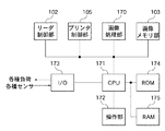
図2は、図1の画像形成装置における各機能部の概略構成を示すブロック図である。 FIG. 2 is a block diagram illustrating a schematic configuration of each functional unit in the image forming apparatus of FIG.
CPU171は、画像形成装置の基本制御を行う(Central Processing Unit)である。CPU171は、制御プログラムが書き込まれたROM174、一時記憶手段としてのRAM175、及び入出力ポート(I/O)173にアドレスバス、データバスを介して接続されている。入出力ポート173には、感光ドラムを駆動する駆動モータやステッピングモータ、クラッチ等の各種負荷(不図示)と、上述した各種センサが接続されている。各種センサから送信された検知信号は、入出力ポート173を介してCPU171へ送信される。
The
CPU171は、ROM174に記憶されている制御プログラムに従って、入出力ポート173を介して順次入出力の制御を行い、画像形成部に画像形成動作を実行させる。また、CPU171には、操作部172が接続されており、操作部172の表示器、キー入力を制御する。操作部172は、リーダ2の上面に配置されており、用紙Pの収納された給紙部(給紙カセット21a〜21d、手差しトレイ27)の選択の指定等が可能である。ユーザは、操作部172のキーを介して、画像形成動作モードやプリント出力モードの表示の切り替えをCPU171に指示する。CPU171は、更に、プリンタ1の状態やキー入力により設定された動作モードの表示を行う。
The
また、CPU171には、リーダ2の制御を行うリーダ制御部102、上述したプリンタ1の画像形成部等を含むプリンタ制御部105と、入力された画像信号を処理する画像処理部170と、処理された画像データを蓄積する画像メモリ部103が接続されている。
Further, the
図3は、給紙カセット21bが開けられた際のプリンタ1の状態例を示す縦断面図である。
FIG. 3 is a longitudinal sectional view showing an example of the state of the
図示のように、給紙カセットに用紙を補給する場合、例えば、給紙カセット21bが開かれる(引き出される)と、搬送パス80aと搬送パス80cとの間の搬送パス80bが抜けて、用紙搬送路が寸断されてしまう。そのため、給紙カセット21bが給紙中のときは当然ジャムが発生してしまう。また、給紙カセット21cまたは給紙カセット21dが給紙中であっても、給紙カセット21bが開かれると、いずれもジャムが発生してしまう。
As shown in the figure, when paper is supplied to the paper feed cassette, for example, when the
一方、給紙カセット21aが給紙中に給紙カセット21bが開かれても、実行中のジョブはそのまま継続することが可能である。つまり、ジョブの実行中には、給紙中の給紙カセットよりも上流(図示例では下段方向)に位置する給紙カセットについては、ジョブを継続したまま給紙カセットを開けて用紙を補給することが可能である。しかしながら、給紙中の給紙カセットおよびそれよりも下流(図示例では上段方向)の給紙カセットについては、ジョブの実行中にこれらの給紙カセットが開かれるとジャムとなってしまうため、ジョブを継続したままでは用紙の補給が不可能である。
On the other hand, even if the
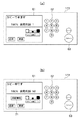
図4は、操作部172の外観と画面表示例を示す図であり、(a)は初期画面(待機状態での画面)、(b)はコピージョブの実行中に表示される画面である。
4A and 4B are diagrams illustrating an appearance and a screen display example of the
図4(a)において、操作部172上には、種々の情報や操作キーを表示する表示器61と、数字キー62と、スタートキー63とが配置されている。表示器61は、タッチパネルディスプレイで構成されており、表示されたキーの入力手段として機能し、画像形成装置の各種設定を行うことが可能である。数字キー62は、主に複写枚数等を設定するときに使われる。スタートキー63は、ユーザがコピーを行うときに押されるキーであり、このキーが押されるとコピー動作が開始となる。
In FIG. 4A, a
例えば、プリンタ1に50部のコピージョブが投入されると、表示器61の表示内容は図4(b)に示す操作画面に切り替わる。この操作画面には、コピー部数を示す「50」と、コピージョブが実行中であることを示す「コピー中です」と、用紙補給キー71が表示される。用紙補給キー71は、ジョブの実行中に用紙を補給するために用いられるキーである。この用紙補給キー71は、ジョブが行われている間中、操作画面上表示され、ジョブが行われていないときには表示されない。ジョブの実行中でないときに給紙カセットを開いても、先に述べたようなジャム等は発生せず、用紙補給を行うことが可能である。そのため、用紙補給キー71はジョブの実行中のみに表示される。
For example, when 50 copy jobs are input to the
図5は、操作部172の外観と画面表示例を示す図であり、(a)は用紙補給キー71が押されたときに表示される画面、(b)は図5(a)の補給給紙段選択画面81で三段目の給紙カセットが選択されたときに表示される画面である。
5A and 5B are diagrams showing an appearance and a screen display example of the
図4(b)に示す操作画面上で用紙補給キー71が押されると、表示器61の表示内容は、図5(a)に示す補給給紙段選択画面81に切り替わる。補給給紙段選択画面81には、給紙段キー811,812,813,814と、画面と閉じて前の画面に戻るための閉じるキー815とが表示される。給紙段キー811〜814は、それぞれ一段目〜四段目の給紙カセット21a〜21dに対応している。給紙中の給紙カセットには、給紙段キー上に「給紙中」の表示がなされる。図示例では、二段目の給紙カセットから給紙されているときの画面であり、給紙段キー812上に「給紙中」と表示されている。ユーザは、補給給紙段選択画面81上で、用紙を補給したい給紙カセットに対応する給紙段キーを選択する。選択された後の処理については後述する。
When the
閉じるキー815が押されると、表示器61の表示内容は、図4(b)に示す操作画面に戻る。なお、プリンタ1のジョブがすべて終了すると、画像形成装置は、操作画面に「ジョブが終了しました」という画面表示をして、図4(a)に示す初期画面に戻る。
When the
例えば、図5(a)に示す補給給紙段選択画面81上で、三段目の給紙段キー813が選択されると、表示器61の表示内容は、図5(b)に示す画面に切り替わる。この場合には、給紙が二段目の給紙カセットからされているため、三段目の給紙カセットに用紙の補給がされても問題がない。そこで、図5(b)に示すように、補給給紙段選択画面81上に用紙の補給を促す表示91(例えば、「補給してください」)が表示される。用紙が補給されても問題がないか否かは、用紙が補給される給紙カセットが、現在給紙中の給紙カセットよりも下流(下段)に位置する給紙カセットか否かで判断される。
For example, when the third paper
図6は、操作部172の外観と画面表示例を示す図であり、(a)は図5(a)の補給給紙段選択画面81で一段目の給紙段キー811が選択されたときに表示される画面である。図6(b)は、図6(a)のジョブ中断指示画面101でOKキー1011が選択されたときに表示される画面である。
6A and 6B are diagrams showing an appearance and a screen display example of the
例えば、図5(a)に示す補給給紙段選択画面81で一段目の給紙段キー811が選択されると、表示器61の表示内容は、図6(a)に示すジョブ中断指示画面101に切り替わる。二段目の給紙カセット21bが給紙中である場合、図5(a)、図5(b)で説明したように、二段目の給紙カセット21bより下流にある一段目の給紙カセット21aに用紙を補給すべく、給紙カセット21aをオープンしてしまうとジャムが発生する。そのため、ジョブの中断作業が必要となる。そこで、補給給紙段選択画面81で選択された給紙カセットが、給紙中かまたは給紙中の給紙カセットよりも下流に位置する場合には、操作部172にジョブ中断指示画面101が表示される。
For example, when the first paper feed stage key 811 is selected on the replenishing paper feed
ジョブ中断指示画面101には、「一段目に用紙を補給したい場合、一度現在のジョブを中断して補給後に再開となります」というジョブを中断する旨の表示と共に、OKキー1011、キャンセルキー1012が表示される。ここでキャンセルキー1012が押されると、何もせずに図5(a)の画面に戻る。一方、OKキー1011が押されると、画像形成装置は現在のジョブの中止動作を開始し、表示器61の表示内容は、図6(b)に示すジョブ中断中画面111に切り替わる。
On the job
図6(b)に示すジョブ中断中画面111には、「ジョブを一時中断中です お待ちください」というジョブが中断中である旨の表示がされる。このジョブ中断中画面111は、プリンタ1内でジョブの中断が完了するまで表示される。ジョブの中断が完了すると、図7に示すジョブ中断画面121に表示が切り替わる。
In the
ジョブ中断画面121には、「ジョブを中断しました 一段目の用紙を補給してください」という用紙補給を促す表示と共に、「補給せずに再開」キー1211が表示される。「補給せずに再開」キー1211が押されると、画像形成装置はジョブを再開し、表示器61の表示内容は、図5(a)に示す補給給紙段選択画面81に戻る。「補給せずに再開」キー1211が押されなかった場合、一段目の給紙カセット21aのオープン、そしてその後クローズが検知されると、画像形成装置はユーザが用紙を補給したと判断し、ジョブを再開する。
On the
上述した画面表示と動作を行うことにより、ユーザはジャム等の問題を起こすことなく、所望の給紙カセットへの用紙補給が可能となる。 By performing the screen display and operation described above, the user can replenish paper in a desired paper feed cassette without causing problems such as jamming.
次に、ジョブ実行中における給紙カセットへの用紙補給に対するプリンタ1の一連の動作処理を図8を用いて説明する。
Next, a series of operation processes of the
図8は、第1の実施形態におけるジョブ実行中の給紙カセットへの用紙補給に対するプリンタ1の動作処理を示すフローチャートである。本処理は、ジョブの実行中に、図4(b)に示す操作画面において用紙補給キー71が押された後に開始される処理である。
FIG. 8 is a flowchart showing an operation process of the
まず、ステップS1300では、CPU171は、操作部172に補給給紙段選択画面81を表示する。次に、CPU171は、補給給紙段選択画面81上で用紙を補給する給紙カセットが指定されたか、つまり給紙段キー811〜814のいずれかが選択されたか否かを判断する(ステップS1301)。次に、CPU171は、ステップS1301で給紙段キー811〜814のいずれも指定されていないと判断すると、閉じるキー815が押されたか否かを判断する(ステップS1302)。ここで閉じるキー815が押されたと判断した場合には本処理を終了する。
First, in step S <b> 1300, the
一方、CPU171は、ステップS1302で閉じるキー815が押されていないと判断した場合には、ジョブが終了したか否かを判断する(ステップS1315)。ジョブが終了したか否かについては、CPU171が、フェイスダウン排紙センサ69をジョブの最終シートが通過したことを確認することで行われる。CPU171は、ジョブが終了したと判断したときは、本処理を終了する。一方、CPU171は、ステップS1315でジョブが終了していないと判断した場合にはステップS1301に戻る。
On the other hand, if the
CPU171は、給紙段キー811〜814のいずれかが指定されたと判断した場合には、指定された給紙カセットが現在給紙中の給紙カセットまたは給紙中の給紙カセットよりも上段(下流)に位置するものか否かを判断する(ステップS1303)。ここでは、例えば、CPU171が、現在給紙中の給紙カセットをRAM175等に記憶しておき、指定された給紙カセットと比較することにより判断される。このとき、給紙カセットに予め位置に応じた値を設定しておき、指定された給紙カセットの値と、現在給紙中の給紙カセットの値と比較して、位置関係を判定するとよい。
If the
ステップS1303の判断の結果、CPU171は、指定された給紙カセットが、現在給紙中の給紙カセットでも給紙中の給紙カセットよりも上段(下流)に位置するものでもない(すなわち上流である)と判断した場合、ステップS1304へ移行する。ステップS1304では、CPU171は、図5(b)に示すように、補給給紙段選択画面81上に用紙補給を促す表示91を行い、ステップS1301に戻る。
As a result of the determination in step S1303, the
ステップ1303において、CPU171は、指定された給紙カセットが現在給紙中の給紙カセット又は給紙中の給紙カセットよりも上段(下流)に位置するものと判断した場合、図6(a)のジョブ中断指示画面101に切り替える(ステップS1305)。次に、CPU171は、ジョブ中断指示画面101上でキャンセルキー1012が選択されたか否かを判断する(ステップS1306)。CPU171は、ステップS1306でキャンセルキー1012が選択されたと判断した場合にはステップS1301に戻る。一方、CPU171は、ステップS1306でキャンセルキー1012が選択されていないと判断した場合には、ジョブ中断指示画面101上のOKキー1011が押された否かを判断する(ステップS1307)。
If the
CPU171は、ステップS1307でOKキー1011が押されていないと判断した場合、ステップS1306へ戻る。一方。ステップS1307でOKキー1011が押されたと判断した場合には、ジョブの中断を開始すると共に、図6(b)に示すジョブ中断中画面111に表示を切り替える(ステップS1308)。
If the
次に、CPU171は、ジョブの中断が終了したか否かを判断する(ステップS1309)。ステップS1309でジョブの中断が終了していないと判断した場合には、ジョブの中断が終了するまでステップS1309を繰り返す。ステップS1309でジョブの中断が終了したと判断した場合には、図7に示すジョブ中断画面121に表示を切り替え(ステップS1310)、ステップS1311に進む。
Next, the
ステップS1311では、CPU171は、ジョブ中断画面121上の「補給せずに再開」キー1211が押されたか否かを判断する。ここで、「補給せずに再開」キー1211が押されたと判断した場合には、CPU171はジョブを再開させて(ステップS1304)、本処理を終了する。
In step S1311, the
一方、CPU171は、ステップS1311で「補給せずに再開」キー1211が押されていないと判断した場合には、ステップS1301で指定された給紙カセットが開けられたか否かを判断する(ステップS1312)。CPU171は、給紙カセット開閉センサ83a〜83dによる検知結果に基づいて、給紙カセット21a〜21dの開閉を判断する。
On the other hand, if the
次に、CPU171は、いずれの給紙カセットも開けられていないと判断した場合にはステップS1311に戻る。一方、ステップS1312で給紙カセットが開けられたと判断した場合、CPU171は、オープンされた給紙カセットが閉じたか否かを判断する(ステップS1313)。ここでも、CPU171は、給紙カセット開閉センサ83a〜83dによる検知結果に基づいて、給紙カセット21a〜21dの開閉を判断する。
Next, when the
CPU171は、ステップS1313で給紙カセットが閉じていないと判断した場合にはステップS1313に戻り、給紙カセットが閉じられるまで繰り返す。CPU171は、ステップS1313で給紙カセットが閉じられたと判断した場合には、ステップS1314に移行し、ジョブを再開させて、本処理を終了する。
If the
上記実施形態によれば、その一部に他の給紙カセットから搬送される用紙が合流する搬送路が設けられている給紙カセットを用いた画像形成装置において、ジョブ実行中にユーザが用紙補給を行う場合、指定された給紙カセットが用紙補給可能か否かを判断する。そして、用紙補給が不可能なときはジョブを中断して、用紙補給を促す。これにより、ジョブの実行中であってもジャム等の問題を起こすことなく、用紙補給が可能となる。 According to the above-described embodiment, in the image forming apparatus using the paper feeding cassette in which a part of the paper feeding cassette that is fed from another paper feeding cassette is provided, the user can replenish paper during the job execution. When performing the above, it is determined whether or not the designated paper cassette can be replenished. When the paper supply is impossible, the job is interrupted to prompt the paper supply. As a result, paper can be replenished without causing a problem such as a jam even during execution of a job.
[第2の実施形態]
本発明の第2の実施形態に係る画像形成装置は、その基本的な構成が上記第1の実施形態に係る画像形成装置と同様であり、第1の実施の形態と同様の部分については、同一の符号を用いてその説明を省略する。以下に、上記第1の実施の形態と異なる点のみを説明する。
[Second Embodiment]
The basic structure of the image forming apparatus according to the second embodiment of the present invention is the same as that of the image forming apparatus according to the first embodiment, and the same parts as those in the first embodiment are described. The description is abbreviate | omitted using the same code | symbol. Only differences from the first embodiment will be described below.
図9は、本発明の第2の実施形態に係る画像形成装置の操作部172に表示される画面表示例を示す図である。図9(a)は、図5(a)の補給給紙段選択画面81の一段目の給紙段キー811が選択されたときの画面を示す図、図9(b)は図9(a)の手差し給紙画面141でOKキーが選択されたときに表示される画面を示す図である。
FIG. 9 is a diagram showing a screen display example displayed on the
図5(a)に示す補給給紙段選択画面81上で一段目の給紙段キー811が選択された場合、表示器61の表示内容は、図9(a)に示す手差し給紙画面141に切り替わる。手差し給紙画面141には、手差しトレイ27に現在給紙中の用紙と同サイズの用紙を置くように促す表示と、OKキー1411と、キャンセルキー1412とが表示される。この手差し給紙画面141上でキャンセルキー1412が押された場合には、表示器61の表示内容は、図5(a)の補給給紙段選択画面81に戻る。一方、OKキー1411が押され、手差しトレイ27に用紙があると判断した場合には、現在実行中のジョブの給紙段は、二段目の給紙カセット21bから手差しトレイ27に切り替わり、表示器61の表示内容は、図9(b)に示す用紙補給画面151に切り替わる。OKキー1411が押されても、手差しトレイ27上に用紙を検知できなかった場合には、表示器61の表示内容は、手差し給紙画面141のままとなる。手差しトレイ27上の用紙の検知は、用紙センサ76により行われる。用紙センサ76による検知結果は、CPU171に通知される。
When the first paper feed stage key 811 is selected on the replenishment paper feed
用紙補給画面151には、用紙を補給するように促す表示と共に、「補給せずに元の給紙に戻す」キー1511が表示される。「補給せずに元の給紙に戻す」キー1511が押されたときは、給紙段が手差しトレイ27から元の給紙カセット21bからの給紙に戻される。
On the
操作部172に用紙補給画面151が表示された状態において、給紙カセット開閉センサ83a〜83dが給紙カセット21a〜21dのいずれかが開かれたことが検知されると、用紙の補給が行われていることが判断される。そして、給紙段が手差しトレイ27からユーザが用紙を補給した給紙カセット、ここでは二段目の給紙カセット21bによる給紙に戻され、表示器61の表示内容は、図10に示す給紙段変更画面161に切り替わる。そして、開かれた給紙カセットが閉じられたことが給紙カセット開閉センサにより検知されて、二段目の給紙カセットからの給紙に戻した旨が表示され、表示器61の表示内容は、図5(a)の補給給紙段選択画面81に戻る。
When the
上述した画像表示と動作を行うことにより、ユーザはジャム等の問題を起こすことなくかつジョブを中断せずに、所望の給紙カセットへの用紙補給が可能となる。 By performing the above-described image display and operation, the user can replenish a desired paper cassette without causing a problem such as a jam and without interrupting the job.
次に、ジョブ実行中における給紙カセットへの用紙補給に対するプリンタ1の一連の動作処理を図11を用いて説明する。
Next, a series of operation processes of the
図11は、第2の実施形態におけるジョブ実行中の給紙カセットへの用紙補給に対するプリンタ1の動作処理を示すフローチャートである。本処理は、ジョブの実行中に、図4(b)に示す操作画面において用紙補給キー71が押された後に開始される処理である。
FIG. 11 is a flowchart illustrating an operation process of the
まず、ステップS1700では、CPU171は、操作部172に補給給紙段選択画面81を表示する。次に、CPU171は、補給給紙段選択画面81上で用紙を補給する給紙カセットが指定されたか、つまり給紙段キー811〜814のいずれかが選択されたか否かを判断する(ステップS1701)。次に、CPU171は、ステップS1701で給紙段キー811〜814のいずれも指定されていないと判断すると、閉じるキー815が押されたか否かを判断する(ステップS1702)。ここで閉じるキー815が押されたと判断した場合には本処理を終了する。
First, in step S <b> 1700, the
一方、CPU171は、ステップS1702で閉じるキー815が押されていないと判断した場合には、ジョブが終了したか否かを判断する(ステップS1716)。CPU171は、ジョブが終了したと判断したときは、本処理を終了する。一方、CPU171は、ステップS1716でジョブが終了していないと判断した場合にはステップS1701に戻る。
On the other hand, if the
CPU171は、給紙段キー811〜814のいずれかが指定されたと判断した場合には、指定された給紙カセットが現在給紙中の給紙カセットまたは給紙中の給紙カセットよりも上段(下流)に位置するものか否かを判断する(ステップS1703)。
If the
ステップS1703の判断の結果、CPU171は、指定された給紙カセットが、現在の給紙中の給紙カセットでも給紙中の給紙カセットよりも上段(下流)に位置するものでもない(すなわち上流である)と判断した場合、ステップS1704へ移行する。ステップS1704では、CPU171は、図5(b)に示すように、補給給紙段選択画面81上に用紙補給を促す表示91を行い、ステップS1701に戻る。
As a result of the determination in step S 1703, the
ステップ1703において、CPU171は、指定された給紙カセットが現在給紙中の給紙カセットまたは給紙中の給紙カセットよりも上段(下流)に位置するものであると判断した場合、図9(a)の手差し給紙画面141に切り替える(ステップS1705)。次に、CPU171は、手差し給紙画面141上でキャンセルキー1412が選択されたか否かを判断する(ステップS1706)。CPU171は、ステップS1706でキャンセルキー1412が選択されたと判断した場合にはステップS1701に戻る。一方、CPU171は、ステップS1706でキャンセルキー1412が選択されていないと判断した場合には、手差し給紙画面141上のOKキー1411が押されたか否かを判断する(ステップS1707)。
If it is determined in step 1703 that the
CPU171は、ステップS1707でOKキー1411が押されていないと判断した場合、ステップS1706に戻る。一方、ステップS1707でOKキーが押されたと判断した場合には、CPU171は、手差しトレイ27に用紙があるか否かを判断する(ステップS1708)。CPU171は、用紙センサ76による検知結果に基づいて、手差しトレイ27上に用紙があるか否かを判断する。
If the
CPU171は、ステップS1708で手差しトレイ27に用紙がないと判断した場合にはステップS1706に戻る。一方、ステップS1708で手差しトレイ27に用紙があると判断した場合には、CPU171は、ステップS1709でジョブを手差しトレイ27による給紙に切り替える。
If the
次に、CPU171は、ステップS1710で図9(b)に示す用紙補給画面151に表示を切り替え、ステップS1711に進む。ステップ1711では、CPU171は、用紙補給画面151上で「補給せずに元の給紙に戻す」キー1511が押されたか否かを判断する。「補給せずに元の給紙に戻す」キー1511が押されていた場合にはステップS1714に進み、給紙段を元の給紙カセットに戻す。一方、CPU171は、ステップS1711で「補給せずに元の給紙に戻す」キー1511が押されていないと判断した場合には、ステップ1701で指定された給紙カセットが開けられたか否かを判断する(ステップS1712)。ここでも、上記第1の実施形態における図8のステップS1312と同様に、CPU171は、給紙カセット開閉センサ83a〜83dによる検知結果に基づいて、給紙カセット21a〜21dの開閉を判断する。
Next, the
次に、CPU171は、いずれの給紙カセットも開けられていないと判断した場合にはステップS1711に戻る。一方、ステップS1712で給紙カセットが開けられたと判断した場合、CPU171は、オープンされた給紙カセットが閉じたか否かを判断する(ステップS1713)。ここでも、CPU171は、給紙カセット開閉センサ83a〜83dによる検知結果に基づいて、給紙カセット21a〜21dの開閉を判断する。
Next, when the
CPU171は、ステップS1713で給紙カセットが閉じていないと判断した場合にはステップS1713に戻り、給紙カセットが閉じられるまで繰り返す。CPU171は、ステップS1713で給紙カセットが閉じられたと判断した場合には、給紙段を元の給紙カセットに戻し(ステップS1714)、図10の給紙段変更画面161に表示を切り替えて(ステップS1715)、本処理を終了する。
If the
上記実施形態によれば、その一部に他の給紙カセットから搬送される用紙が合流する搬送路が設けられている給紙カセットを用いた画像形成装置において、ジョブ実行中にユーザが用紙補給を行う場合、指定された給紙カセットが用紙補給可能か否かを判断する。そして、用紙補給が不可能なときは手差しトレイからの給紙に一時的に切り替え、用紙補給後に元の給紙カセットからの給紙に戻す。これにより、給紙カセットの一部に他の給紙カセットから給紙される用紙が搬送される搬送路が設けられている画像形成装置において、画像形成動作の実行中でもジャム等の問題を起こすことなくかつジョブを中断せずに、用紙補給が可能となる。 According to the above-described embodiment, in the image forming apparatus using the paper feeding cassette in which a part of the paper feeding cassette that is fed from another paper feeding cassette is provided, the user can replenish paper during the job execution. When performing the above, it is determined whether or not the designated paper cassette can be replenished. When the paper supply is impossible, the paper supply is temporarily switched to the paper feed from the manual feed tray, and the paper is returned to the original paper feed cassette after the paper supply. As a result, in an image forming apparatus in which a part of the paper feed cassette is provided with a transport path through which paper fed from another paper feed cassette is transported, problems such as jamming may occur even during the image forming operation. This makes it possible to supply paper without interrupting the job.
また、本発明の目的は、以下の処理を実行することによって達成される。即ち、上述した実施形態の機能を実現するソフトウェアのプログラムコードを記録した記憶媒体を、システム或いは装置に供給し、そのシステム或いは装置のコンピュータ(またはCPUやMPU等)が記憶媒体に格納されたプログラムコードを読み出す処理である。この場合、記憶媒体から読み出されたプログラムコード自体が前述した実施の形態の機能を実現することになり、そのプログラムコードおよび該プログラムコードを記憶した記憶媒体は本発明を構成することになる。 The object of the present invention is achieved by executing the following processing. That is, a storage medium that records a program code of software that realizes the functions of the above-described embodiments is supplied to a system or apparatus, and a computer (or CPU, MPU, etc.) of the system or apparatus is stored in the storage medium. This is the process of reading the code. In this case, the program code itself read from the storage medium realizes the functions of the above-described embodiment, and the program code and the storage medium storing the program code constitute the present invention.
また、プログラムコードを供給するための記憶媒体としては、次のものを用いることができる。例えば、フロッピー(登録商標)ディスク、ハードディスク、光磁気ディスク、CD−ROM、CD−R、CD−RW、DVD−ROM、DVD−RAM、DVD−RW、DVD+RW、磁気テープ、不揮発性のメモリカード、ROM等である。または、プログラムコードをネットワークを介してダウンロードしてもよい。 Moreover, the following can be used as a storage medium for supplying the program code. For example, floppy (registered trademark) disk, hard disk, magneto-optical disk, CD-ROM, CD-R, CD-RW, DVD-ROM, DVD-RAM, DVD-RW, DVD + RW, magnetic tape, nonvolatile memory card, ROM or the like. Alternatively, the program code may be downloaded via a network.
また、コンピュータが読み出したプログラムコードを実行することにより、上記実施の形態の機能が実現される場合も本発明に含まれる。加えて、そのプログラムコードの指示に基づき、コンピュータ上で稼動しているOS(オペレーティングシステム)等が実際の処理の一部または全部を行い、その処理によって前述した実施形態の機能が実現される場合も含まれる。 Further, the present invention includes a case where the function of the above-described embodiment is realized by executing the program code read by the computer. In addition, an OS (operating system) running on the computer performs part or all of the actual processing based on an instruction of the program code, and the functions of the above-described embodiments are realized by the processing. Is also included.
さらに、前述した実施形態の機能が以下の処理によって実現される場合も本発明に含まれる。即ち、記憶媒体から読み出されたプログラムコードが、コンピュータに挿入された機能拡張ボードやコンピュータに接続された機能拡張ユニットに備わるメモリに書き込まれる。その後、そのプログラムコードの指示に基づき、その機能拡張ボードや機能拡張ユニットに備わるCPU等が実際の処理の一部または全部を行う場合である。 Furthermore, a case where the functions of the above-described embodiment are realized by the following processing is also included in the present invention. That is, the program code read from the storage medium is written in a memory provided in a function expansion board inserted into the computer or a function expansion unit connected to the computer. Thereafter, based on the instruction of the program code, the CPU or the like provided in the function expansion board or function expansion unit performs part or all of the actual processing.
上記実施の形態では、プリンタ1の印刷方式を電子写真方式とした場合を例に挙げたが、本発明は、電子写真方式に限定されるものではない。インクジェット方式、熱転写方式、感熱方式、静電方式、放電破壊方式など各種印刷方式に適用することができる。上記プログラムの形態は、オブジェクトコード、インタプリタにより実行されるプログラムコード、OS(オペレーティングシステム)に供給されるスクリプトデータ等の形態から成ってもよい。
In the above embodiment, the case where the printing method of the
1 プリンタ
21a,21b,21c,21d 給紙カセット
61 表示器
81 補給給紙段選択画面
83a,83b,83c,83d 給紙カセット開閉センサ
105 プリンタ制御部
171 CPU
172 操作部
173 入出力ポート(I/O)
DESCRIPTION OF
172 Operation unit 173 I / O port (I / O)
Claims (7)
収納した用紙の給紙を行う給紙手段であって、他の給紙手段から給紙された用紙が搬送される搬送路を有する複数の給紙手段と、
前記複数の給紙手段のうちの1つを指定するための指定手段と、
画像形成動作の実行中に前記画像形成動作で使用中の給紙手段とは異なる他の給紙手段が前記指定手段で指定された場合、指定された給紙手段に用紙補給ができるか否かを判断する判断手段と、
前記判断手段により用紙補給ができないと判断された場合、実行中の画像形成動作で使用中の給紙手段からの給紙を中断し、前記指定手段により指定された給紙手段への用紙補給後に、中断された給紙を再開する制御手段とを備えることを特徴とする画像形成装置。 In an image forming apparatus that performs an image forming operation,
A plurality of paper feed means for feeding the stored paper, the paper feed means having a transport path for transporting paper fed from other paper feed means;
Designation means for designating one of the plurality of paper feeding means;
Whether or not the designated paper feeding means can be replenished when another paper feeding means different from the paper feeding means being used in the image forming operation is designated by the designation means during execution of the image forming operation. A judging means for judging
When the determination unit determines that the paper cannot be supplied, the paper supply from the paper supply unit in use in the image forming operation being performed is interrupted, and after the paper supply to the paper supply unit specified by the specification unit is performed And an image forming apparatus comprising: a control unit that resumes the interrupted paper feeding.
収納した用紙の給紙を行う給紙手段であって、他の給紙手段から給紙された用紙が搬送される搬送路を有する複数の給紙手段と、
前記複数の給紙手段のうちの1つを指定するための指定手段と、
画像形成動作の実行中に前記画像形成動作で使用中の給紙手段とは異なる他の給紙手段が前記指定手段で指定された場合、前記指定手段により指定された給紙手段に用紙補給ができるか否かを判断する判断手段と、
前記判断手段により用紙補給ができないと判断された場合、給紙が可能な他の給紙手段に切り替え、用紙補給後に元の給紙手段からの給紙に戻す制御手段とを備えることを特徴とする画像形成装置。 In an image forming apparatus that performs an image forming operation,
A plurality of paper feed means for feeding the stored paper, the paper feed means having a transport path for transporting paper fed from other paper feed means;
Designation means for designating one of the plurality of paper feeding means;
When another sheet feeding unit different from the sheet feeding unit being used in the image forming operation is designated by the designation unit during the execution of the image forming operation, the sheet feeding unit designated by the designation unit is supplied with paper. A judgment means for judging whether or not it is possible;
And a control unit that switches to another paper feeding unit that can feed paper when the judgment unit determines that the paper cannot be replenished, and returns the paper to the original paper feeding unit after the paper is replenished. Image forming apparatus.
画像形成動作の実行中に前記画像形成動作で使用中の給紙手段とは異なる他の給紙手段が前記指定手段で指定された場合、指定された給紙手段に用紙補給ができるか否かを判断する判断工程と、
前記判断工程にて用紙補給ができないと判断された場合、実行中の画像形成動作で使用中の給紙手段からの給紙を中断し、前記指定手段により指定された給紙手段への用紙補給後に、中断された給紙を再開する制御工程とを備えることを特徴とする給紙方法。 A plurality of sheet feeding units each having a conveyance path for conveying a sheet fed from another sheet feeding unit; An image forming apparatus comprising a designating unit for designating one, and a paper feeding method for an image forming apparatus that performs an image forming operation.
Whether or not the designated paper feeding means can be replenished when another paper feeding means different from the paper feeding means being used in the image forming operation is designated by the designation means during execution of the image forming operation. A judging process for judging
If it is determined in the determining step that the paper cannot be supplied, the paper supply from the paper supply unit in use in the image forming operation being executed is interrupted, and the paper supply to the paper supply unit designated by the designation unit is performed. And a control step of resuming the interrupted paper feeding later.
画像形成動作の実行中に前記画像形成動作で使用中の給紙手段とは異なる他の給紙手段が前記指定手段で指定された場合、指定された給紙手段に用紙補給ができるか否かを判断する判断工程と、
前記判断工程にて用紙補給ができないと判断された場合、給紙が可能な他の給紙手段に切り替え、用紙補給後に元の給紙手段からの給紙に戻す制御工程とを備えることを特徴とする給紙方法。 A plurality of sheet feeding units each having a conveyance path for conveying a sheet fed from another sheet feeding unit; An image forming apparatus comprising a designating unit for designating one, and a paper feeding method for an image forming apparatus that performs an image forming operation.
Whether or not the designated paper feeding means can be replenished when another paper feeding means different from the paper feeding means being used in the image forming operation is designated by the designation means during execution of the image forming operation. A judging process for judging
And a control step of switching to another paper feeding unit capable of paper feeding and returning to the paper feeding from the original paper feeding unit after the paper replenishment when it is judged that the paper cannot be replenished in the judgment step. Paper feeding method.
Priority Applications (1)
| Application Number | Priority Date | Filing Date | Title |
|---|---|---|---|
| JP2008146856A JP2009292575A (en) | 2008-06-04 | 2008-06-04 | Image forming device and its paper feed method |
Applications Claiming Priority (1)
| Application Number | Priority Date | Filing Date | Title |
|---|---|---|---|
| JP2008146856A JP2009292575A (en) | 2008-06-04 | 2008-06-04 | Image forming device and its paper feed method |
Publications (1)
| Publication Number | Publication Date |
|---|---|
| JP2009292575A true JP2009292575A (en) | 2009-12-17 |
Family
ID=41541143
Family Applications (1)
| Application Number | Title | Priority Date | Filing Date |
|---|---|---|---|
| JP2008146856A Pending JP2009292575A (en) | 2008-06-04 | 2008-06-04 | Image forming device and its paper feed method |
Country Status (1)
| Country | Link |
|---|---|
| JP (1) | JP2009292575A (en) |
Cited By (3)
| Publication number | Priority date | Publication date | Assignee | Title |
|---|---|---|---|---|
| JP2012011681A (en) * | 2010-07-01 | 2012-01-19 | Konica Minolta Business Technologies Inc | Image forming system |
| JP2015202642A (en) * | 2014-04-15 | 2015-11-16 | キヤノン株式会社 | Printing device, printing control method, program and recording medium |
| JP2022131557A (en) * | 2021-02-26 | 2022-09-07 | 沖電気工業株式会社 | image forming device |
-
2008
- 2008-06-04 JP JP2008146856A patent/JP2009292575A/en active Pending
Cited By (4)
| Publication number | Priority date | Publication date | Assignee | Title |
|---|---|---|---|---|
| JP2012011681A (en) * | 2010-07-01 | 2012-01-19 | Konica Minolta Business Technologies Inc | Image forming system |
| JP2015202642A (en) * | 2014-04-15 | 2015-11-16 | キヤノン株式会社 | Printing device, printing control method, program and recording medium |
| JP2022131557A (en) * | 2021-02-26 | 2022-09-07 | 沖電気工業株式会社 | image forming device |
| JP7683241B2 (en) | 2021-02-26 | 2025-05-27 | 沖電気工業株式会社 | Image forming device |
Similar Documents
| Publication | Publication Date | Title |
|---|---|---|
| JP5188109B2 (en) | Image forming apparatus | |
| US7292358B2 (en) | Image forming apparatus | |
| JP2020184687A (en) | Image forming apparatus, image forming method, and program therefor | |
| JP5277744B2 (en) | Image forming apparatus, intermediate transfer belt drive control method, computer program, and recording medium | |
| JP2002173252A (en) | Image forming device and control method thereof | |
| JP6366359B2 (en) | Image forming apparatus | |
| JP2008254868A (en) | Image forming apparatus | |
| JP2022071751A (en) | Image forming device, information processing device | |
| JP2009292575A (en) | Image forming device and its paper feed method | |
| JP5975790B2 (en) | Image forming apparatus | |
| JP4942151B2 (en) | Image forming system and image forming apparatus | |
| JP2007310365A (en) | Method for controlling image forming apparatus | |
| US7340193B2 (en) | Image forming apparatus, and storage medium storing a control program for the same | |
| US7835685B2 (en) | Image forming apparatus and control method therefor | |
| JP2006337548A (en) | Image forming apparatus and method, and program | |
| JP4590245B2 (en) | Image forming apparatus | |
| JP2004038048A (en) | Image forming device | |
| JP5332154B2 (en) | Image forming apparatus | |
| US20250321524A1 (en) | Image forming apparatus and information processing device | |
| JP2003237188A (en) | Image forming apparatus and image forming method | |
| JP2006139109A (en) | Image forming apparatus | |
| JP2008039990A (en) | Color image forming apparatus | |
| JP2003280486A (en) | Image forming device | |
| JP2005266419A (en) | Color image forming apparatus | |
| JP2008222417A (en) | Image forming apparatus |