JP2009299500A - Apparatus and method for determining deterioration of air-fuel ratio sensor - Google Patents
Apparatus and method for determining deterioration of air-fuel ratio sensor Download PDFInfo
- Publication number
- JP2009299500A JP2009299500A JP2008151960A JP2008151960A JP2009299500A JP 2009299500 A JP2009299500 A JP 2009299500A JP 2008151960 A JP2008151960 A JP 2008151960A JP 2008151960 A JP2008151960 A JP 2008151960A JP 2009299500 A JP2009299500 A JP 2009299500A
- Authority
- JP
- Japan
- Prior art keywords
- air
- fuel ratio
- output
- ratio sensor
- fuel
- Prior art date
- Legal status (The legal status is an assumption and is not a legal conclusion. Google has not performed a legal analysis and makes no representation as to the accuracy of the status listed.)
- Granted
Links
Images


Classifications
-
- Y—GENERAL TAGGING OF NEW TECHNOLOGICAL DEVELOPMENTS; GENERAL TAGGING OF CROSS-SECTIONAL TECHNOLOGIES SPANNING OVER SEVERAL SECTIONS OF THE IPC; TECHNICAL SUBJECTS COVERED BY FORMER USPC CROSS-REFERENCE ART COLLECTIONS [XRACs] AND DIGESTS
- Y02—TECHNOLOGIES OR APPLICATIONS FOR MITIGATION OR ADAPTATION AGAINST CLIMATE CHANGE
- Y02T—CLIMATE CHANGE MITIGATION TECHNOLOGIES RELATED TO TRANSPORTATION
- Y02T10/00—Road transport of goods or passengers
- Y02T10/10—Internal combustion engine [ICE] based vehicles
- Y02T10/40—Engine management systems
Landscapes
- Exhaust Gas After Treatment (AREA)
- Electrical Control Of Air Or Fuel Supplied To Internal-Combustion Engine (AREA)
- Combined Controls Of Internal Combustion Engines (AREA)
Abstract
【課題】エミッションの悪化を抑制しつつ、触媒の劣化判定を行う。
【解決手段】空燃比センサの劣化判定装置(1)は、内燃機関(10)の動作状態を検出する動作状態検出手段(31)と、検出された動作状態が所定状態であることを条件に、排気通路(14)における第1空燃比がストイキオメトリに近づき、且つ複数の気筒(12a〜12d)のうち少なくとも二つの気筒の各々における第2空燃比が第1範囲内で相異なるように燃料供給手段(15)を制御した後に、第1空燃比がストイキオメトリに近づき、且つ第2空燃比が第2範囲内で相異なるように燃料供給手段を制御する制御手段(31)と、第2空燃比が第1範囲内で相異なる場合の空燃比センサの出力である第1出力、及び第2空燃比が第2範囲内で相異なる場合の空燃比センサの出力である第2出力に基づいて空燃比センサが劣化しているか否かを判定する判定手段(31)とを備える。
【選択図】図2Deterioration determination of a catalyst is performed while suppressing deterioration of emissions.
An air-fuel ratio sensor deterioration determination device (1) is provided on the condition that an operating state detecting means (31) for detecting an operating state of an internal combustion engine (10) and a detected operating state being a predetermined state. The first air-fuel ratio in the exhaust passage (14) approaches the stoichiometry, and the second air-fuel ratio in each of at least two of the plurality of cylinders (12a to 12d) is different within the first range. Control means (31) for controlling the fuel supply means so that the first air-fuel ratio approaches the stoichiometry and the second air-fuel ratio differs within the second range after controlling the fuel supply means (15); A first output that is the output of the air-fuel ratio sensor when the second air-fuel ratio is different within the first range, and a second output that is the output of the air-fuel ratio sensor when the second air-fuel ratio is different within the second range The air-fuel ratio sensor Dolphin and a determination means for determining whether (31).
[Selection] Figure 2
Description
本発明は、空燃比センサに備わる触媒の劣化判定を行う劣化判定装置及び方法の技術分野に関する。 The present invention relates to a technical field of a deterioration determination apparatus and method for determining deterioration of a catalyst provided in an air-fuel ratio sensor.
この種の装置として、空燃比を大きく変更した際におけるセンサ触媒(即ち、O2センサに到達する排気を平衡化するための触媒)を備えるO2センサ出力の遅れ時間を計測し、該計測された遅れ時間が所定時間以下になったときに、センサ触媒が劣化したと判定する空燃比制御装置が提案されている(特許文献1参照)。 As this type of device, an O 2 sensor output delay time provided with a sensor catalyst (that is, a catalyst for balancing exhaust gas reaching the O 2 sensor) when the air-fuel ratio is greatly changed is measured, and the measured time is measured. An air-fuel ratio control device that determines that the sensor catalyst has deteriorated when the delay time becomes equal to or less than a predetermined time has been proposed (see Patent Document 1).
尚、特許文献2には、触媒層及びヒータを備える空燃比センサの温度が触媒層の劣化開始温度以上であるか否かを判別し、劣化開始温度以上である場合には、所定の下限温度まで空燃比センサの温度が低下するようにヒータへの通電量を制御することによって、触媒層の劣化を防止する技術が記載されている。また、特許文献3には、ガスエンジンの排気通路に設けられた触媒及びヒータを備える空燃比センサにおける排気ガス側電極の表面を摂氏600度以上に保つことによって、水素によるセンサの出力ずれを防止する技術が記載されている。
In Patent Document 2, it is determined whether or not the temperature of the air-fuel ratio sensor including the catalyst layer and the heater is equal to or higher than the deterioration start temperature of the catalyst layer. A technique for preventing deterioration of the catalyst layer is described by controlling the amount of current supplied to the heater so that the temperature of the air-fuel ratio sensor is lowered. Further,
しかしながら、特許文献1に記載の技術では、触媒の劣化判定のために空燃比を大きく変更しなければならず、エミッションが悪化する可能性があるという技術的問題点がある。また、特許文献2及び3の各々に記載の技術では、触媒の劣化判定を行うことは困難であるという技術的問題点がある。
However, the technique described in Patent Document 1 has a technical problem that the air-fuel ratio has to be changed greatly in order to determine the deterioration of the catalyst, and the emission may be deteriorated. Further, the techniques described in
本発明は、例えば上記問題点に鑑みてなされたものであり、エミッションの悪化を抑制しつつ、触媒の劣化判定を行うことができる空燃比センサの劣化判定装置及び方法を提供することを課題とする。 The present invention has been made in view of the above problems, for example, and it is an object of the present invention to provide an air-fuel ratio sensor deterioration determination apparatus and method capable of performing catalyst deterioration determination while suppressing deterioration of emissions. To do.
本発明の空燃比センサの劣化判定装置は、上記課題を解決するために、複数の気筒と、前記複数の気筒の各々に相互に独立して燃料を供給可能な燃料供給手段と、一端が前記複数の気筒に夫々接続された排気通路に配置された触媒と、前記排気通路における前記触媒の上流側に配置された触媒層を有する空燃比センサとを備える内燃機関における前記空燃比センサの劣化判定装置であって、前記内燃機関の動作状態を検出する動作状態検出手段と、前記検出された動作状態が所定状態であることを条件に、前記排気通路における第1空燃比がストイキオメトリに近づき、且つ前記複数の気筒のうち少なくとも二つの気筒の各々における第2空燃比が第1範囲内で相互に異なるように前記燃料供給手段を制御した後に、前記第1空燃比がストイキオメトリに近づき、且つ前記第2空燃比が第2範囲内で相互に異なるように前記燃料供給手段を制御する制御手段と、前記第2空燃比が前記第1範囲内で相互に異なる場合の前記空燃比センサの出力である第1出力、及び前記第2空燃比が前記第2範囲内で相互に異なる場合の前記空燃比センサの出力である第2出力に基づいて前記空燃比センサが劣化しているか否かを判定する判定手段とを備える。 In order to solve the above-described problem, the air-fuel ratio sensor deterioration determination apparatus of the present invention includes a plurality of cylinders, a fuel supply unit capable of supplying fuel to each of the plurality of cylinders, and one end of the fuel supply unit. Deterioration determination of the air-fuel ratio sensor in an internal combustion engine comprising: a catalyst disposed in an exhaust passage connected to each of a plurality of cylinders; and an air-fuel ratio sensor having a catalyst layer disposed upstream of the catalyst in the exhaust passage. And an operating state detecting means for detecting an operating state of the internal combustion engine, and the first air-fuel ratio in the exhaust passage approaches stoichiometry on condition that the detected operating state is a predetermined state. And after controlling the fuel supply means so that the second air-fuel ratio in each of at least two of the plurality of cylinders is different within a first range, the first air-fuel ratio is stoichiometric. Control means for controlling the fuel supply means so that the second air-fuel ratio is different within a second range, and the second air-fuel ratio is different within the first range. The air-fuel ratio sensor deteriorates based on the first output that is the output of the air-fuel ratio sensor and the second output that is the output of the air-fuel ratio sensor when the second air-fuel ratio is different within the second range. Determination means for determining whether or not the
本発明の空燃比センサの劣化判定装置によれば、例えば自動車等のエンジンである内燃機関は、複数の気筒と、該複数の気筒の各々に相互に独立して燃料を供給可能な燃料供給手段と、一端が複数の気筒に夫々接続された排気通路に配置された、例えば三元触媒等の触媒と、排気通路における触媒の上流側に配置された触媒層を有する空燃比センサとを備えて構成される。 According to the deterioration determination device for an air-fuel ratio sensor of the present invention, an internal combustion engine, which is an engine of an automobile, for example, includes a plurality of cylinders and a fuel supply means capable of supplying fuel to each of the plurality of cylinders independently of each other. And a catalyst such as a three-way catalyst disposed at one end of each of the exhaust passages connected to the plurality of cylinders, and an air-fuel ratio sensor having a catalyst layer disposed on the upstream side of the catalyst in the exhaust passage. Composed.
ここに、本発明に係る「空燃比センサ」とは、内燃機関における空燃比を検出するために、少なくとも排気通路を流れる排出ガスにおける酸素濃度に対応する物理量を出力することが可能な手段を包括する概念であり、例えばリニア空燃比センサ、O2センサ等である。尚、「酸素濃度に対応する物理量」は、例えば電流値、電圧値等であってよい。 Here, the “air-fuel ratio sensor” according to the present invention includes means capable of outputting a physical quantity corresponding to at least the oxygen concentration in the exhaust gas flowing through the exhaust passage in order to detect the air-fuel ratio in the internal combustion engine. For example, a linear air-fuel ratio sensor, an O 2 sensor, or the like. The “physical quantity corresponding to the oxygen concentration” may be, for example, a current value, a voltage value, or the like.
本発明に係る「空燃比センサ」は、該空燃比センサの本体部分である「センサ素子」と、「触媒層」とを有する。ここに、「センサ素子」とは、排出ガスにおける酸素濃度の変化に応じて、センサ素子本体の或いはセンサ素子から適宜電極等を介して取り出される、例えば電流値、電圧値等の何らかの物理量を変化させ得る素子を包括する概念であり、例えばジルコニア(ZrO2)又はそれにCaO等を安定剤として固溶させた酸素イオン伝導性酸化物焼結体等である。 The “air-fuel ratio sensor” according to the present invention includes a “sensor element” that is a main part of the air-fuel ratio sensor, and a “catalyst layer”. Here, the “sensor element” refers to any physical quantity such as a current value or a voltage value that is taken out of the sensor element body or an appropriate electrode from the sensor element according to a change in oxygen concentration in the exhaust gas. For example, an oxygen ion conductive oxide sintered body in which zirconia (ZrO 2 ) or CaO or the like is solid-solved as a stabilizer.
動作時には、センサ素子の両端における酸素濃度の差に応じて酸素イオンの移動が生じるため、この酸素イオンの移動に起因して生じる電流又は電圧等の物理量を、本発明に係る「酸素濃度に対応する物理量」として出力することにより、排出ガス中の酸素濃度の検出が可能となる。尚、センサ素子の形状は、酸素濃度の検出を可能とする限りにおいて何ら限定されない。例えば有底円筒形状であってもよいし、平板状であってもよい。 During operation, oxygen ions move in accordance with the difference in oxygen concentration at both ends of the sensor element. Therefore, the physical quantity such as current or voltage caused by the movement of oxygen ions is expressed as “corresponding to oxygen concentration” according to the present invention. By outputting as “physical quantity to be performed”, the oxygen concentration in the exhaust gas can be detected. The shape of the sensor element is not limited as long as the oxygen concentration can be detected. For example, it may be a bottomed cylindrical shape or a flat plate shape.
また、本発明に係る「触媒層」とは、排出ガス中の水素がセンサ素子に与える影響を、触媒層が設けられない場合と比較して、いくらかなりとも低減し得る手段を包括する概念であり、例えば、触媒担体としてのアルミナ等の多孔質層に白金、ロジウム等の触媒成分を担持させたものである。尚、触媒層は、センサ素子に対する水素の影響を低減可能な限りにおいて、どのような位置に設置されていてもよいが、望ましくは、センサ素子と一体として形成されている。 In addition, the “catalyst layer” according to the present invention is a concept that includes means that can significantly reduce the influence of hydrogen in exhaust gas on the sensor element as compared with the case where no catalyst layer is provided. For example, a catalyst layer such as platinum or rhodium is supported on a porous layer such as alumina as a catalyst carrier. The catalyst layer may be installed at any position as long as the influence of hydrogen on the sensor element can be reduced, but is desirably formed integrally with the sensor element.
ここで、「排出ガス中の水素がセンサ素子に与える影響」とは、センサ素子に到達する排出ガス中の酸素濃度が水素に起因して、実際の酸素濃度から変化してしまうことを意味する。センサ素子は、上述の如く、センサ素子の両端における酸素濃度の差(典型的には、排出ガス中の酸素濃度と外部大気中の酸素濃度との差)に起因して生じる物理量により排出ガス中の酸素濃度を検出している。従って、排出ガス中に水素が存在すると、検出される排出ガス中の酸素濃度(即ち、センサの出力)に誤差が生じることが本願発明者の研究により判明している。この排出ガス中の水素は、気筒で発生する、例えばH2O、CO、HC(未燃炭化水素)等が水性ガス還元反応を生じることにより生成される。 Here, “the influence of hydrogen in the exhaust gas on the sensor element” means that the oxygen concentration in the exhaust gas reaching the sensor element changes from the actual oxygen concentration due to the hydrogen. . As described above, the sensor element has a difference in oxygen concentration at both ends of the sensor element (typically, a difference between the oxygen concentration in the exhaust gas and the oxygen concentration in the external atmosphere). The oxygen concentration is detected. Accordingly, it has been found by the inventor's research that when hydrogen is present in the exhaust gas, an error occurs in the oxygen concentration (that is, sensor output) in the detected exhaust gas. The hydrogen in the exhaust gas is generated when, for example, H 2 O, CO, HC (unburned hydrocarbon) generated in the cylinder undergoes a water gas reduction reaction.
尚、「一端が複数の気筒に夫々接続された排気通路」とは、排気通路の一端が複数の気筒の各々に対応して複数本に分岐しており、複数本に分岐した排気通路の各々が対応する気筒に接続されていることを意味する。 The “exhaust passage with one end connected to each of the plurality of cylinders” means that one end of the exhaust passage branches into a plurality of cylinders corresponding to each of the plurality of cylinders, and each of the exhaust passages branched into a plurality of cylinders. Is connected to the corresponding cylinder.
当該空燃比センサの劣化判定装置の動作時には、先ず、例えばメモリ、プロセッサ等を備える動作状態検出手段により内燃機関の動作状態が検出される。ここに、「動作状態を検出」とは、内燃機関の動作に係る、例えば回転数、冷却水温度、吸入空気量、供給燃料量等の何らかの物理量又はパラメータを一又は複数検出することを意味する。 When the deterioration determination device for the air-fuel ratio sensor is in operation, first, the operation state of the internal combustion engine is detected by an operation state detection means including, for example, a memory, a processor, and the like. Here, “detecting the operating state” means detecting one or more physical quantities or parameters related to the operation of the internal combustion engine, such as the rotational speed, the cooling water temperature, the intake air amount, the supplied fuel amount, and the like. .
次に、例えばメモリ、プロセッサ等を備える制御手段は、検出された動作状態が所定状態であることを条件に、排気通路における第1空燃比がストイキオメトリに近づき、且つ複数の気筒のうち少なくとも二つの気筒の各々における第2空燃比が第1範囲内で相互に異なるように燃料供給手段を制御する。その後、制御手段は、第1空燃比がストイキオメトリに近づき、且つ第2空燃比が第2範囲内で相互に異なるように燃料供給手段を制御する。 Next, the control means including, for example, a memory, a processor, or the like, on condition that the detected operation state is a predetermined state, the first air-fuel ratio in the exhaust passage approaches the stoichiometry, and at least of the plurality of cylinders The fuel supply means is controlled so that the second air-fuel ratio in each of the two cylinders is different from each other within the first range. Thereafter, the control means controls the fuel supply means so that the first air-fuel ratio approaches the stoichiometry and the second air-fuel ratio differs from each other within the second range.
ここに、本発明に係る「所定状態」とは、第2空燃比が相互に異なるように燃料供給手段を制御するか否かを決定する状態であり、予め固定状態として又は何らかのパラメータに応じた可変状態として設定される状態である。このような所定状態は、経験的若しくは実験的に又はシミュレーションによって、例えば、各気筒から排出された排出ガスが空燃比センサに到達するまでの時間がほぼ一定となる状態として設定すればよい。 Here, the “predetermined state” according to the present invention is a state in which it is determined whether or not to control the fuel supply means so that the second air-fuel ratios differ from each other. This is a state set as a variable state. Such a predetermined state may be set as a state in which the time until the exhaust gas discharged from each cylinder reaches the air-fuel ratio sensor becomes substantially constant, for example, empirically, experimentally, or by simulation.
「第1空燃比がストイキオメトリに近づき、且つ第2空燃比が相互に異なるように」とは、少なくとも二つの気筒のうち一の気筒の空燃比がリッチとなり、他の気筒の空燃比がリーンとなるように燃料が供給されるが、各気筒に供給される燃料量及び吸入される空気量を合わせた全体の空燃比がストイキオメトリに近づくようにという意味である。 “The first air-fuel ratio approaches the stoichiometry and the second air-fuel ratio is different from each other” means that the air-fuel ratio of one of at least two cylinders is rich and the air-fuel ratio of the other cylinders is This means that the fuel is supplied so as to be lean, but the total air-fuel ratio of the fuel amount supplied to each cylinder and the intake air amount approaches the stoichiometry.
本発明に係る「第1範囲」とは、空燃比がストイキオメトリである場合に比べて、排出ガス中の水素濃度が高くなるような範囲を意味する。また、本発明に係る「第2範囲」とは、第2空燃比が第1範囲内で相互に異なるように燃料供給手段を制御した場合に比べて、排出ガス中の水素濃度が高くなるような範囲を意味する。 The “first range” according to the present invention means a range in which the hydrogen concentration in the exhaust gas is higher than when the air-fuel ratio is stoichiometry. Further, the “second range” according to the present invention means that the hydrogen concentration in the exhaust gas becomes higher than that in the case where the fuel supply means is controlled so that the second air-fuel ratios are different from each other within the first range. Meaning a range.
例えばメモリ、プロセッサ、コンパレータ等を備えてなる判定手段は、第2空燃比が第1範囲内で相互に異なる場合の空燃比センサの出力である第1出力、及び第2空燃比が第2範囲内で相互に異なる場合の空燃比センサの出力である第2出力に基づいて空燃比センサが劣化しているか否かを判定する。ここに、「空燃比センサが劣化している」とは、空燃比センサが備える触媒層が劣化していることを意味する。 For example, the determination unit including a memory, a processor, a comparator, and the like includes a first output that is an output of the air-fuel ratio sensor when the second air-fuel ratio is different within the first range, and a second air-fuel ratio that is in the second range. It is determined whether the air-fuel ratio sensor has deteriorated based on the second output which is the output of the air-fuel ratio sensor when they differ from each other. Here, “the air-fuel ratio sensor has deteriorated” means that the catalyst layer included in the air-fuel ratio sensor has deteriorated.
本願発明者の研究によれば、空燃比センサが備える触媒層の劣化判定のために、空燃比をリッチ又はリーンに変更しなければならず、劣化判定に起因してエミッションが悪化するおそれがある。加えて、単純に空燃比をリッチ又はリーンに変更しただけでは、触媒層が劣化しているのか、複数の気筒の相互間の空燃比がばらつくことに起因して排出ガス中の水素濃度が変動しているのかを判別することが困難であることが判明している。 According to the research of the present inventor, the air-fuel ratio must be changed to rich or lean for the deterioration determination of the catalyst layer provided in the air-fuel ratio sensor, and the emission may be deteriorated due to the deterioration determination. . In addition, simply changing the air-fuel ratio to rich or lean simply fluctuates the hydrogen concentration in the exhaust gas because the catalyst layer has deteriorated or the air-fuel ratio among multiple cylinders varies. It has proved difficult to determine whether or not
しかるに本発明では、空燃比センサが備える触媒層の劣化判定を行う際に、制御手段によって、排気通路における第1空燃比がストイキオメトリに近づくように燃料供給手段が制御される。これにより、劣化判定に起因するエミッションの悪化を抑制することができる。 However, in the present invention, when the deterioration determination of the catalyst layer included in the air-fuel ratio sensor is performed, the fuel supply means is controlled by the control means so that the first air-fuel ratio in the exhaust passage approaches the stoichiometry. Thereby, the deterioration of the emission resulting from the deterioration determination can be suppressed.
加えて、判定手段によって、第2空燃比が第1範囲内で相互に異なる場合の空燃比センサの出力である第1出力、及び第2空燃比が第2範囲内で相互に異なる場合の空燃比センサの出力である第2出力に基づいて空燃比センサが劣化しているか否かが判定される。このように、二つの場合の空燃比センサの出力に基づいて劣化判定を行っているので、触媒層が劣化しているのか、複数の気筒の相互間の空燃比がばらつくことに起因して排出ガス中の水素濃度が変動しているのかを判別することができ、空燃比センサが備える触媒層が劣化しているか否かを正しく判定できる。 In addition, the determination means causes the first output, which is the output of the air-fuel ratio sensor when the second air-fuel ratio is different within the first range, and the air when the second air-fuel ratio is different within the second range. It is determined whether the air-fuel ratio sensor has deteriorated based on the second output that is the output of the fuel ratio sensor. As described above, since the deterioration determination is performed based on the output of the air-fuel ratio sensor in the two cases, the exhaust is caused by whether the catalyst layer is deteriorated or the air-fuel ratio among a plurality of cylinders varies. It is possible to determine whether the hydrogen concentration in the gas is fluctuating, and it is possible to correctly determine whether the catalyst layer included in the air-fuel ratio sensor has deteriorated.
以上の結果、本発明の空燃比センサの劣化判定装置によれば、エミッションの悪化を抑制しつつ、空燃比センサが備える触媒層の劣化判定を行うことができる。 As a result, according to the deterioration determination device for an air-fuel ratio sensor of the present invention, it is possible to determine the deterioration of the catalyst layer included in the air-fuel ratio sensor while suppressing the deterioration of emissions.
本発明の空燃比センサの劣化判定装置の一態様では、前記判定手段は、前記第1出力及び前記第2出力の出力差が第1閾値より大きい場合に前記空燃比センサが劣化していると判定し、前記出力差が前記第1閾値より小さい場合に前記空燃比センサが劣化していないと判定する。 In one aspect of the deterioration determination device for an air-fuel ratio sensor according to the present invention, the determination means determines that the air-fuel ratio sensor has deteriorated when an output difference between the first output and the second output is greater than a first threshold. When the output difference is smaller than the first threshold, it is determined that the air-fuel ratio sensor has not deteriorated.
この態様によれば、判定手段は、第1出力及び第2出力の出力差が第1閾値より大きいこと、又は小さいことを判定して、空燃比センサが劣化しているか否かを判定することができる。尚、出力差と第1閾値とが「等しい」場合には、どちらかの場合に含めて扱えばよい。 According to this aspect, the determination unit determines whether the output difference between the first output and the second output is larger than or smaller than the first threshold value, and determines whether or not the air-fuel ratio sensor has deteriorated. Can do. When the output difference and the first threshold value are “equal”, they may be included in either case.
ここに、本発明に係る「第1閾値」とは、空燃比センサが劣化しているか否かを決定する値であり、予め固定値として又は何らかのパラメータに応じた可変値として設定される値である。このような第1閾値は、経験的若しくは実験的に又はシミュレーションによって、例えば、出力差と触媒層の劣化の度合いとの関係を求めて、該求められた関係に基づいて、劣化の度合いが許容範囲を超えた時の出力差として設定すればよい。 Here, the “first threshold” according to the present invention is a value that determines whether or not the air-fuel ratio sensor has deteriorated, and is a value that is set in advance as a fixed value or as a variable value according to some parameter. is there. Such a first threshold value is obtained empirically, experimentally or by simulation, for example, by determining the relationship between the output difference and the degree of deterioration of the catalyst layer, and allowing the degree of deterioration based on the obtained relationship. What is necessary is just to set as an output difference when it exceeds the range.
或いは、本発明の空燃比センサの劣化判定装置の他の態様では、前記判定手段は、前記第1出力に対する前記第2出力の出力比が第2閾値より大きい場合に前記空燃比センサが劣化していると判定し、前記出力比が前記第2閾値より小さい場合に劣化していないと判定する。 Alternatively, in another aspect of the deterioration determination device for an air-fuel ratio sensor of the present invention, the determination means deteriorates the air-fuel ratio sensor when an output ratio of the second output to the first output is greater than a second threshold. If the output ratio is smaller than the second threshold value, it is determined that there is no deterioration.
この態様によれば、判定手段は、第1出力に対する第2出力の出力比が第2閾値より大きいこと、又は小さいことを判定して、空燃比センサが劣化しているか否かを判定することができる。尚、出力比と第2閾値とが「等しい」場合には、どちらかの場合に含めて扱えばよい。 According to this aspect, the determination means determines whether the output ratio of the second output to the first output is larger than or smaller than the second threshold value, and determines whether or not the air-fuel ratio sensor has deteriorated. Can do. When the output ratio and the second threshold value are “equal”, they may be included in either case.
ここに、本発明に係る「第2閾値」とは、空燃比センサが劣化しているか否かを決定する値であり、予め固定値として又は何らかのパラメータに応じた可変値として設定される値である。このような第2閾値は、経験的若しくは実験的に又はシミュレーションによって、例えば、出力比と触媒層の劣化の度合いとの関係を求めて、該求められた関係に基づいて、劣化の度合いが許容範囲を超えた時の出力比として設定すればよい。 Here, the “second threshold value” according to the present invention is a value that determines whether or not the air-fuel ratio sensor has deteriorated, and is a value that is set in advance as a fixed value or a variable value according to some parameter. is there. Such a second threshold value is obtained, for example, by empirically or experimentally or by simulation, by determining the relationship between the output ratio and the degree of deterioration of the catalyst layer, and allowing the degree of deterioration based on the obtained relationship. What is necessary is just to set as an output ratio when it exceeds the range.
或いは、本発明の空燃比センサの劣化判定装置の他の態様では、前記判定手段は、前記第1出力の出力軌跡長である第1出力軌跡長及び前記第2出力の出力軌跡長である第2出力軌跡長を演算する演算手段を含み、前記演算された第1出力軌跡長及び前記演算された第2出力軌跡長の軌跡長差が第3閾値より大きいことを条件に前記空燃比センサが劣化していると判定し、前記軌跡長差が前記第3閾値より小さい場合に前記空燃比センサが劣化していないと判定する。 Alternatively, in another aspect of the deterioration determination device for an air-fuel ratio sensor of the present invention, the determination means includes a first output trajectory length that is an output trajectory length of the first output and an output trajectory length of the second output. The air-fuel ratio sensor includes a computing means for computing a two-output trajectory length, provided that a trajectory length difference between the computed first output trajectory length and the computed second output trajectory length is greater than a third threshold value. It is determined that the air-fuel ratio sensor has deteriorated, and when the trajectory length difference is smaller than the third threshold value, it is determined that the air-fuel ratio sensor has not deteriorated.
この態様によれば、例えばメモリ、プロセッサ等を備えてなる演算手段は、第1出力の出力軌跡長である第1出力軌跡長及び第2出力の出力軌跡長である第2出力軌跡長を演算する。判定手段は、演算された第1出力軌跡長及び演算された第2出力軌跡長の軌跡長差が第3閾値より大きいこと、又は小さいことを判定して、空燃比センサが劣化しているか否かを判定することができる。ここに、「出力軌跡長」とは、所定期間における空燃比センサの出力波形の長さを意味する。 According to this aspect, for example, the computing means including a memory, a processor, etc. computes the first output trajectory length that is the output trajectory length of the first output and the second output trajectory length that is the output trajectory length of the second output. To do. The determination means determines whether the difference between the calculated first output trajectory length and the calculated second output trajectory length is larger or smaller than the third threshold value, and whether or not the air-fuel ratio sensor has deteriorated. Can be determined. Here, the “output trajectory length” means the length of the output waveform of the air-fuel ratio sensor during a predetermined period.
ここに、本発明に係る「第3閾値」とは、空燃比センサが劣化しているか否かを決定する値であり、予め固定値として又は何らかのパラメータに応じた可変値として設定される値である。このような第3閾値は、経験的若しくは実験的に又はシミュレーションによって、例えば、軌跡長差と触媒層の劣化の度合いとの関係を求めて、該求められた関係に基づいて、劣化の度合いが許容範囲を超えた時の軌跡長差として設定すればよい。 Here, the “third threshold value” according to the present invention is a value that determines whether or not the air-fuel ratio sensor is deteriorated, and is a value that is set in advance as a fixed value or as a variable value according to some parameter. is there. Such a third threshold value is obtained empirically, experimentally, or by simulation, for example, by obtaining the relationship between the trajectory length difference and the degree of deterioration of the catalyst layer, and the degree of deterioration is determined based on the obtained relationship. What is necessary is just to set as a locus | trajectory length difference when exceeding an allowable range.
或いは、本発明の空燃比センサの劣化判定装置の他の態様では、前記判定手段は、前記第1出力の出力軌跡長である第1出力軌跡長及び前記第2出力の出力軌跡長である第2出力軌跡長を演算する演算手段を含み、前記演算された第1出力軌跡長に対する前記演算された第2出力軌跡長の軌跡長比が第4閾値より大きいことを条件に前記空燃比センサが劣化していると判定し、前記軌跡長比が前記第4閾値より小さい場合に前記空燃比センサが劣化していないと判定する。 Alternatively, in another aspect of the deterioration determination device for an air-fuel ratio sensor of the present invention, the determination means includes a first output trajectory length that is an output trajectory length of the first output and an output trajectory length of the second output. The air-fuel ratio sensor includes a calculation means for calculating a two-output trajectory length, on the condition that a trajectory length ratio of the calculated second output trajectory length to the calculated first output trajectory length is greater than a fourth threshold value. It is determined that the air-fuel ratio sensor has deteriorated, and when the trajectory length ratio is smaller than the fourth threshold value, it is determined that the air-fuel ratio sensor has not deteriorated.
この態様によれば、判定手段は、演算された第1出力軌跡長に対する演算された第2出力軌跡長の軌跡長比が第4閾値より大きいこと、又は小さいことを判定して、空燃比センサが劣化しているか否かを判定することができる。 According to this aspect, the determination unit determines that the locus length ratio of the calculated second output locus length to the calculated first output locus length is larger or smaller than the fourth threshold value, and the air-fuel ratio sensor. It can be determined whether or not the battery has deteriorated.
ここに、本発明に係る「第4閾値」とは、空燃比センサが劣化しているか否かを決定する値であり、予め固定値として又は何らかのパラメータに応じた可変値として設定される値である。このような第4閾値は、経験的若しくは実験的に又はシミュレーションによって、例えば、軌跡長比と触媒層の劣化の度合いとの関係を求めて、該求められた関係に基づいて、劣化の度合いが許容範囲を超えた時の軌跡長比として設定すればよい。 Here, the “fourth threshold value” according to the present invention is a value that determines whether or not the air-fuel ratio sensor is deteriorated, and is a value that is set in advance as a fixed value or a variable value according to some parameter. is there. Such a fourth threshold is obtained, for example, by empirically or experimentally or by simulation, by determining the relationship between the trajectory length ratio and the degree of deterioration of the catalyst layer, and the degree of deterioration is determined based on the obtained relationship. What is necessary is just to set as locus | trajectory length ratio when exceeding an allowable range.
本発明の空燃比センサの劣化判定方法は、上記課題を解決するために、複数の気筒と、前記複数の気筒の各々に相互に独立して燃料を供給可能な燃料供給手段と、一端が前記複数の気筒に夫々接続された排気通路に配置された触媒と、前記排気通路における前記触媒の上流側に配置された触媒層を有する空燃比センサとを備える内燃機関における前記空燃比センサの劣化判定方法であって、前記内燃機関の動作状態を検出する動作状態検出工程と、前記検出された動作状態が所定状態であることを条件に、前記排気通路における第1空燃比がストイキオメトリに近づき、且つ前記複数の気筒のうち少なくとも二つの気筒の各々における第2空燃比が第1範囲内で相互に異なるように前記燃料供給手段を制御する第1制御工程と、前記第1空燃比がストイキオメトリに近づき、且つ前記第2空燃比が第2範囲内で相互に異なるように前記燃料供給手段を制御する第2制御工程と、前記第2空燃比が前記第1範囲内で相互に異なる場合の前記空燃比センサの出力である第1出力、及び前記第2空燃比が前記第2範囲内で相互に異なる場合の前記空燃比センサの出力である第2出力に基づいて前記空燃比センサが劣化しているか否かを判定する判定工程とを備える。 In order to solve the above problem, the air-fuel ratio sensor deterioration determination method of the present invention includes a plurality of cylinders, a fuel supply means capable of supplying fuel to each of the plurality of cylinders, and one end of the fuel supply means. Deterioration determination of the air-fuel ratio sensor in an internal combustion engine comprising: a catalyst disposed in an exhaust passage connected to each of a plurality of cylinders; and an air-fuel ratio sensor having a catalyst layer disposed upstream of the catalyst in the exhaust passage. In the method, the first air-fuel ratio in the exhaust passage approaches the stoichiometry on condition that the operating state detecting step for detecting the operating state of the internal combustion engine and that the detected operating state is a predetermined state. And a first control step of controlling the fuel supply means so that a second air-fuel ratio in each of at least two of the plurality of cylinders is different within a first range; and the first air-fuel And a second control step for controlling the fuel supply means so that the second air-fuel ratio is different within the second range, and the second air-fuel ratio is within the first range. The first output that is the output of the air-fuel ratio sensor when the air-fuel ratio sensor is different from the first output, and the second output that is the output of the air-fuel ratio sensor when the second air-fuel ratio is different within the second range. A determination step of determining whether or not the fuel ratio sensor has deteriorated.
本発明の空燃比センサの劣化判定方法によれば、上述した本発明の空燃比センサの劣化判定装置と同様に、エミッションの悪化を抑制しつつ、空燃比センサが備える触媒層の劣化判定を行うことができる。 According to the air-fuel ratio sensor deterioration determination method of the present invention, as in the air-fuel ratio sensor deterioration determination device of the present invention described above, the deterioration determination of the catalyst layer included in the air-fuel ratio sensor is performed while suppressing the deterioration of emissions. be able to.
尚、本発明の空燃比センサの劣化判定方法においても、上述した本発明の空燃比センサの劣化判定装置と同様の各種態様を採ることが可能である。 In the air-fuel ratio sensor deterioration determination method of the present invention, various aspects similar to the above-described air-fuel ratio sensor deterioration determination device of the present invention can be employed.
本発明の作用及びその他の利得は次に説明する実施するための最良の形態から明らかにされよう。 The operation and other advantages of the present invention will become apparent from the best mode for carrying out the invention described below.
以下、本発明に係る空燃比センサの劣化判定装置の実施形態を図面に基づいて説明する。 Embodiments of an air-fuel ratio sensor deterioration determination apparatus according to the present invention will be described below with reference to the drawings.
<第1実施形態>
本発明の空燃比センサの劣化判定装置に係る第1実施形態を、図1から図3を参照して説明する。
<First Embodiment>
A first embodiment of an air-fuel ratio sensor deterioration determination apparatus according to the present invention will be described with reference to FIGS.
先ず、本実施形態に係る劣化判定装置の構成を、図1を参照して説明する。ここに、図1は、本実施形態に係る劣化判定装置の構成を示すブロック図である。 First, the configuration of the deterioration determination apparatus according to the present embodiment will be described with reference to FIG. FIG. 1 is a block diagram showing the configuration of the deterioration determination apparatus according to this embodiment.
図1において、エンジン10の本体部11の複数の気筒12a〜12dには、吸気通路13及び排気通路14が夫々接続されている。複数の気筒12a〜12dの各々には、ここでは図示しない、例えばガソリン等の燃料を貯留する燃料タンクに、デリバリーパイプ16を介して接続されている燃料噴射弁15が設けられている。
In FIG. 1, an
排気通路14には、例えば三元触媒等の触媒17と、該触媒17の上流側に配置された空燃比センサ21と、触媒17の下流側に配置されたO2センサ22とが設けられている。空燃比センサ21には、該空燃比センサ21に対する排出ガス中の水素の影響を低減するための触媒層(図示せず)が設けられている。
In the
尚、本実施形態に係る「エンジン10」及び「燃料噴射弁15」は、夫々、本発明に係る「内燃機関」及び「燃料供給手段」の一例である。
The “
本実施形態に係る劣化判定装置1は、本発明に係る「動作状態検出手段」、「制御手段」、「判定手段」及び「演算手段」の一例としてのECU(Electronic Control Unit)31を備えて構成されている。本実施形態では、各種電子制御用のECU31を、劣化判定装置1の一部として用いている。
The degradation determination apparatus 1 according to the present embodiment includes an ECU (Electronic Control Unit) 31 as an example of “operation state detection means”, “control means”, “determination means”, and “calculation means” according to the present invention. It is configured. In this embodiment, the
尚、ECU31は、空燃比センサ21の出力に基づいて、各気筒12a〜12dにおける空燃比が所定値となるように燃料噴射弁15を制御する(即ち、空燃比フィードバック制御を実行する)。
The
次に、以上のように構成された劣化判定装置1を備える車両の走行中において、ECU31が実行する空燃比センサ21の劣化判定処理について、図2のフローチャートを参照して説明する。
Next, the deterioration determination process of the air-
図2において、先ず、ECU31は、エンジン10の動作状態が所定の動作状態であるか否かを判定する(ステップS101)。ここで、ECU31は、例えば冷却水の温度が所定温度より高いか否か、空燃比センサ21及びO2センサ22各々の温度が、例えば摂氏700度〜800度である活性温度範囲内であるか否か、触媒17の温度が、例えば摂氏400度〜600度である活性温度範囲内であるか否か、各気筒12a〜12dに吸入される空気量及び供給される燃料量が一定であるか否か、並びに、空燃比フィードバックが実行されているか否か等を判定して、エンジン10の動作状態が所定の動作状態であるか否かを判定する。
In FIG. 2, the
エンジン10の動作状態が所定の動作状態であると判定された場合(ステップS101:Yes)、ECU31は、空燃比フィードバック(F/B)制御を停止する(ステップS102)。他方、エンジン10の動作状態が所定の動作状態でないと判定された場合(ステップS101:No)、一旦処理を終了する。
When it is determined that the operating state of the
空燃比フィードバック制御を停止した後、ECU31は、各気筒12a〜12dにおける空燃比(即ち、本発明に係る「第2空燃比」)が、例えばストイキオメトリに対して±3%である第1範囲内で相互に異なるように、且つ排気通路14における空燃比(即ち、本発明に係る「第1空燃比」)がストイキオメトリに近づくように燃料噴射弁15を制御して、各気筒12a〜12dに供給される燃料量(即ち、噴射量)を第1所定量だけばらつかせる(ステップS103)。
After stopping the air-fuel ratio feedback control, the
具体的には例えば、ECU31は、気筒12a及び12c各々における空燃比がリッチとなるように、且つ気筒12b及び12d各々における空燃比がリーンとなるように燃料噴射弁15を制御する。尚、「排気通路14における空燃比」とは、典型的には、排気通路14のうち合流部分より下流における空燃比を意味する。
Specifically, for example, the
上記ステップS103の処理と並行して、ECU31は、本発明に係る「第1出力」の一例としての空燃比センサ21の出力値の平均値(AFAV1)を取得する(ステップS104)。
In parallel with the process of step S103, the
次に、ECU31は、各気筒12a〜12dにおける空燃比が、例えばストイキオメトリに対して±5%である第2範囲内で相互に異なるように、且つ排気通路14における空燃比がストイキオメトリに近づくように燃料噴射弁15を制御して、各気筒12a〜12dに供給される燃料量を第2所定量だけばらつかせる(ステップS105)。
Next, the
上記ステップS105の処理と並行して、ECU31は、本発明に係る「第2出力」の一例としての空燃比センサ21の出力値の平均値(AFAV2)を取得する(ステップS106)。
In parallel with the process of step S105, the
次に、ECU31は、本発明に係る「出力差」の一例としての、取得されたAFAV2から取得されたAFAV1を引いた値(AFAV2−AFAV1)を算出する(ステップS107)。続いて、ECU31は、算出された値が第1閾値より大きいか否かを判定する(ステップS108)。
Next, the
算出された値が第1閾値より大きいと判定された場合(ステップS108:Yes)、ECU31は、空燃比センサ21が備える触媒層が劣化していると判定して(ステップS109)、一旦処理を終了する。他方、算出された値が第1閾値より小さいと判定された場合(ステップS108:No)、ECU31は、空燃比センサ21が備える触媒層が劣化していない(即ち、正常である)と判定して(ステップS110)、一旦処理を終了する。
When it is determined that the calculated value is greater than the first threshold (step S108: Yes), the
ここで、空燃比センサ21が備える触媒層が正常な場合及び劣化している場合の各々における空燃比センサ21の出力値の平均値について、図3を参照して説明する。ここに、図3は、本実施形態に係る空燃比センサの出力値の平均値の一例を示す概念図である。尚、図中の実線a及びbは、夫々、触媒層が正常な場合の出力値の平均値及び触媒層が劣化している場合の出力値の平均値である。
Here, the average value of the output value of the air-
空燃比センサ21が備える触媒層が正常である場合、上記ステップS104の処理において取得されるAFAV1はd1となり、上記ステップS106の処理において取得されるAFAV2はd2となる。従って、上記ステップS107の処理において算出される値は、d2−d1となる。
When the catalyst layer included in the air-
他方、空燃比センサ21が備える触媒層が劣化している場合、上記ステップS104の処理において取得されるAFAV1はd3となり、上記ステップS106の処理において取得されるAFAV2はd4となる。従って、上記ステップS107の処理において算出される値は、d4−d3となる。
On the other hand, when the catalyst layer included in the air-
このように、空燃比センサ21が備える触媒層が劣化している場合は、算出された値が大きくなるので、上記ステップS108の処理において、算出された値が第1閾値より大きいか否かを判定することによって、空燃比センサ21が備える触媒層が劣化しているか否かを判定することができる。
As described above, when the catalyst layer included in the air-
<第2実施形態>
本発明の空燃比センサの劣化判定装置に係る第2実施形態を、図4を参照して説明する。第2実施形態では、ECUが実行する劣化判定処理が一部異なる以外は、第1実施形態の構成と同様である。よって、第2実施形態について、第1実施形態と重複する説明を省略すると共に、図面上における共通箇所には同一符号を付して示し、基本的に異なる点についてのみ、図4を参照して説明する。ここに、図4は、本実施形態においてECU31が実行する空燃比センサ21の劣化判定処理を示すフローチャートである。
Second Embodiment
A second embodiment of the air-fuel ratio sensor deterioration determination apparatus of the present invention will be described with reference to FIG. The second embodiment is the same as the configuration of the first embodiment except that the deterioration determination process executed by the ECU is partially different. Therefore, in the second embodiment, the description overlapping with that of the first embodiment is omitted, and the common portions in the drawing are denoted by the same reference numerals, and only fundamentally different points are described with reference to FIG. explain. FIG. 4 is a flowchart showing the deterioration determination process of the air-
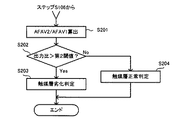
図4において、ECU31は、本発明に係る「出力比」の一例としての、取得されたAFAV1に対する取得されたAFAV2の比(AFAV2/AFAV1)を算出する(ステップS201)。続いて、ECU31は、算出された比が第2閾値より大きいか否かを判定する(ステップS202)。
In FIG. 4, the
具体的には例えば、空燃比センサ21が備える触媒層が正常である場合、上記ステップS201の処理において算出される比(AFAV2/AFAV1)はd2/d1となる(図3参照)。他方、空燃比センサ21が備える触媒層が劣化している場合、上記ステップS201の処理において算出される比(AFAV2/AFAV1)はd4/d3となる(図3参照)。
Specifically, for example, when the catalyst layer included in the air-
このように、空燃比センサ21が備える触媒層が劣化している場合は、算出された比が大きくなるので、上記ステップS202の処理において、算出された比が第2閾値より大きいか否かを判定することによって、空燃比センサ21が備える触媒層が劣化しているか否かを判定することができる。
As described above, when the catalyst layer included in the air-
算出された比が第2閾値より大きいと判定された場合(ステップS202:Yes)、ECU31は、空燃比センサ21が備える触媒層が劣化していると判定して(ステップS203)、一旦処理を終了する。他方、算出された比が第2閾値より小さいと判定された場合(ステップS202:No)、ECU31は、空燃比センサ21が備える触媒層が劣化していないと判定して(ステップS204)、一旦処理を終了する。
When it is determined that the calculated ratio is greater than the second threshold value (step S202: Yes), the
<第3実施形態>
本発明の空燃比センサの劣化判定装置に係る第3実施形態を、図5を参照して説明する。第3実施形態では、ECUが実行する劣化判定処理が一部異なる以外は、第1実施形態の構成と同様である。よって、第3実施形態について、第1実施形態と重複する説明を省略すると共に、図面上における共通箇所には同一符号を付して示し、基本的に異なる点についてのみ、図5を参照して説明する。ここに、図5は、本実施形態においてECU31が実行する空燃比センサ21の劣化判定処理を示すフローチャートである。
<Third Embodiment>
A third embodiment of the deterioration determination device for an air-fuel ratio sensor of the present invention will be described with reference to FIG. The third embodiment is the same as the configuration of the first embodiment except that the deterioration determination process executed by the ECU is partially different. Therefore, the description of the third embodiment that is the same as that of the first embodiment is omitted, and common portions in the drawing are denoted by the same reference numerals, and only fundamentally different points are described with reference to FIG. explain. FIG. 5 is a flowchart showing the deterioration determination process of the air-
図5において、ECU31は、図2に示したステップS103の処理と並行して、本発明に係る「第1出力軌跡長」の一例としての空燃比センサ21の出力波形の長さ(AFSUM1)を取得する(ステップS301)。
In FIG. 5, in parallel with the process of step S <b> 103 shown in FIG. 2, the
次に、ECU31は、各気筒12a〜12dにおける空燃比が、例えばストイキオメトリに対して±5%である第2範囲内で相互に異なるように、且つ排気通路14における空燃比がストイキオメトリに近づくように燃料噴射弁15を制御して、各気筒12a〜12dに供給される燃料量を第2所定量だけばらつかせる(ステップS302)。
Next, the
上記ステップS302の処理と並行して、ECU31は、本発明に係る「第2出力軌跡長」の一例としての空燃比センサ21の出力波形の長さ(AFSUM2)を取得する(ステップS303)。
In parallel with the process of step S302, the
次に、ECU31は、本発明に係る「軌跡長差」の一例としての、取得されたAFSUM2から取得されたAFSUM1を引いた値(AFSUM2−AFSUM1)を算出する(ステップS304)。続いて、ECU31は、算出された値が第3閾値より大きいか否かを判定する(ステップS305)。
Next, the
算出された値が第3閾値より大きいと判定された場合(ステップS305:Yes)、ECU31は、空燃比センサ21が備える触媒層が劣化していると判定して(ステップS306)、一旦処理を終了する。他方、算出された値が第3閾値より小さいと判定された場合(ステップS305:No)、ECU31は、空燃比センサ21が備える触媒層が劣化していないと判定して(ステップS307)、一旦処理を終了する。
When it is determined that the calculated value is greater than the third threshold value (step S305: Yes), the
尚、空燃比センサ21の出力波形の長さは、空燃比センサ21が備える触媒層が劣化している程長くなる。また、各気筒12a〜12dに供給される燃料量のばらつきが大きい程、空燃比センサ21の出力波形の長さが長くなる。従って、空燃比センサ21が備える触媒層が劣化している程、上記ステップS304において算出された値(AFSUM2−AFSUM1)が大きくなる。
Note that the length of the output waveform of the air-
<第4実施形態>
本発明の空燃比センサの劣化判定装置に係る第4実施形態を、図6を参照して説明する。第4実施形態では、ECUが実行する劣化判定処理が一部異なる以外は、第3実施形態の構成と同様である。よって第4実施形態について、第3実施形態と重複する説明を省略すると共に、図面上における共通箇所には同一符号を付して示し、基本的に異なる点についてのみ、図6を参照して説明する。ここに、図6は、本実施形態おいてECU31が実行する空燃比センサ21の劣化判定処理を示すフローチャートである。
<Fourth embodiment>
A fourth embodiment of the air-fuel ratio sensor deterioration determination apparatus of the present invention will be described with reference to FIG. The fourth embodiment is the same as the configuration of the third embodiment except that the deterioration determination process executed by the ECU is partially different. Therefore, the description of the fourth embodiment that is the same as that of the third embodiment is omitted, and common portions in the drawing are denoted by the same reference numerals, and only differences are basically described with reference to FIG. To do. FIG. 6 is a flowchart showing the deterioration determination process of the air-
図6において、ECU31は、本発明に係る「軌跡長比」の一例としての、取得されたAFSUM1に対する取得されたAFSUM2の比(AFSUM2/AFSUM1)を算出する(ステップS401)。続いて、ECU31は、算出された比が第4閾値より大きいか否かを判定する(ステップS402)。
In FIG. 6, the
算出された比が第4閾値より大きいと判定された場合(ステップS402:Yes)、ECU31は、空燃比センサ21が備える触媒層が劣化していると判定して(ステップS403)、一旦処理を終了する。他方、算出された比が第4閾値より小さいと判定された場合(ステップS402:No)、ECU31は、空燃比センサ21が備える触媒層が劣化していないと判定して(ステップS404)、一旦処理を終了する。
When it is determined that the calculated ratio is greater than the fourth threshold (step S402: Yes), the
尚、上述の如く、空燃比センサ21の出力波形の長さは、空燃比センサ21が備える触媒層が劣化している程長くなる。また、各気筒12a〜12dに供給される燃料量のばらつきが大きい程、空燃比センサ21の出力波形の長さが長くなる。従って、空燃比センサ21が備える触媒層が劣化している程、上記ステップS401において算出された比(AFSUM2/AFSUM1)が大きくなる。
As described above, the length of the output waveform of the air-
尚、本発明は、上述した実施形態に限られるものではなく、請求の範囲及び明細書全体から読み取れる発明の要旨、或いは思想に反しない範囲で適宜変更可能であり、そのような変更を伴う空燃比センサの劣化判定装置及び方法もまた、本発明の技術的範囲に含まれるものである。 Note that the present invention is not limited to the above-described embodiment, and can be appropriately changed without departing from the gist or concept of the invention that can be read from the claims and the entire specification. An apparatus and method for determining the deterioration of the fuel ratio sensor are also included in the technical scope of the present invention.
1…劣化判定装置、10…エンジン、11…本体部、12a〜12d…気筒、13…吸気通路、14…排気通路、15…燃料噴射弁、16…デリバリーパイプ、17…触媒、21…空燃比センサ、22…O2センサ、31…ECU DESCRIPTION OF SYMBOLS 1 ... Degradation determination apparatus, 10 ... Engine, 11 ... Main part, 12a-12d ... Cylinder, 13 ... Intake passage, 14 ... Exhaust passage, 15 ... Fuel injection valve, 16 ... Delivery pipe, 17 ... Catalyst, 21 ... Air-fuel ratio Sensor, 22 ... O 2 sensor, 31 ... ECU
Claims (6)
前記内燃機関の動作状態を検出する動作状態検出手段と、
前記検出された動作状態が所定状態であることを条件に、前記排気通路における第1空燃比がストイキオメトリに近づき、且つ前記複数の気筒のうち少なくとも二つの気筒の各々における第2空燃比が第1範囲内で相互に異なるように前記燃料供給手段を制御した後に、前記第1空燃比がストイキオメトリに近づき、且つ前記第2空燃比が第2範囲内で相互に異なるように前記燃料供給手段を制御する制御手段と、
前記第2空燃比が前記第1範囲内で相互に異なる場合の前記空燃比センサの出力である第1出力、及び前記第2空燃比が前記第2範囲内で相互に異なる場合の前記空燃比センサの出力である第2出力に基づいて前記空燃比センサが劣化しているか否かを判定する判定手段と
を備えることを特徴とする空燃比センサの劣化判定装置。 A plurality of cylinders, a fuel supply means capable of supplying fuel to each of the plurality of cylinders independently of each other, a catalyst disposed at one end of each of the plurality of cylinders connected to the plurality of cylinders, and the exhaust passage A deterioration determination device for the air-fuel ratio sensor in an internal combustion engine, comprising: an air-fuel ratio sensor having a catalyst layer disposed upstream of the catalyst in
An operating state detecting means for detecting an operating state of the internal combustion engine;
On condition that the detected operating state is a predetermined state, the first air-fuel ratio in the exhaust passage approaches the stoichiometry, and the second air-fuel ratio in each of at least two cylinders of the plurality of cylinders After controlling the fuel supply means so as to be different from each other within the first range, the fuel so that the first air-fuel ratio approaches the stoichiometry and the second air-fuel ratio differs from each other within the second range. Control means for controlling the supply means;
The first output, which is the output of the air-fuel ratio sensor when the second air-fuel ratio is different from each other within the first range, and the air-fuel ratio when the second air-fuel ratio is different from each other within the second range. An air-fuel ratio sensor deterioration determination apparatus comprising: a determination unit that determines whether or not the air-fuel ratio sensor has deteriorated based on a second output that is an output of the sensor.
前記第1出力及び前記第2出力の出力差が第1閾値より大きい場合に前記空燃比センサが劣化していると判定し、
前記出力差が前記第1閾値より小さい場合に前記空燃比センサが劣化していないと判定する
ことを特徴とする請求項1に記載の空燃比センサの劣化判定装置。 The determination means includes
When the output difference between the first output and the second output is greater than a first threshold, it is determined that the air-fuel ratio sensor has deteriorated,
The deterioration determination device for an air-fuel ratio sensor according to claim 1, wherein when the output difference is smaller than the first threshold, it is determined that the air-fuel ratio sensor has not deteriorated.
前記第1出力に対する前記第2出力の出力比が第2閾値より大きい場合に前記空燃比センサが劣化していると判定し、
前記出力比が前記第2閾値より小さい場合に劣化していないと判定する
ことを特徴とする請求項1に記載の空燃比センサの劣化判定装置。 The determination means includes
When the output ratio of the second output to the first output is greater than a second threshold, it is determined that the air-fuel ratio sensor has deteriorated,
The deterioration determination device for an air-fuel ratio sensor according to claim 1, wherein it is determined that the output ratio is not deteriorated when the output ratio is smaller than the second threshold value.
前記第1出力の出力軌跡長である第1出力軌跡長及び前記第2出力の出力軌跡長である第2出力軌跡長を演算する演算手段を含み、
前記演算された第1出力軌跡長及び前記演算された第2出力軌跡長の軌跡長差が第3閾値より大きいことを条件に前記空燃比センサが劣化していると判定し、
前記軌跡長差が前記第3閾値より小さい場合に前記空燃比センサが劣化していないと判定する
ことを特徴とする請求項1に記載の空燃比センサの劣化判定装置。 The determination means includes
Calculating means for calculating a first output trajectory length that is an output trajectory length of the first output and a second output trajectory length that is an output trajectory length of the second output;
Determining that the air-fuel ratio sensor has deteriorated on the condition that a path length difference between the calculated first output path length and the calculated second output path length is greater than a third threshold;
2. The air-fuel ratio sensor deterioration determination device according to claim 1, wherein when the trajectory length difference is smaller than the third threshold value, it is determined that the air-fuel ratio sensor has not deteriorated.
前記第1出力の出力軌跡長である第1出力軌跡長及び前記第2出力の出力軌跡長である第2出力軌跡長を演算する演算手段を含み、
前記演算された第1出力軌跡長に対する前記演算された第2出力軌跡長の軌跡長比が第4閾値より大きいことを条件に前記空燃比センサが劣化していると判定し、
前記軌跡長比が前記第4閾値より小さい場合に前記空燃比センサが劣化していないと判定する
ことを特徴とする請求項1に記載の空燃比センサの劣化判定装置。 The determination means includes
Calculating means for calculating a first output trajectory length that is an output trajectory length of the first output and a second output trajectory length that is an output trajectory length of the second output;
Determining that the air-fuel ratio sensor is deteriorated on the condition that a locus length ratio of the calculated second output locus length to the calculated first output locus length is larger than a fourth threshold;
The deterioration determination device for an air-fuel ratio sensor according to claim 1, wherein the air-fuel ratio sensor is determined not to be deteriorated when the locus length ratio is smaller than the fourth threshold value.
前記内燃機関の動作状態を検出する動作状態検出工程と、
前記検出された動作状態が所定状態であることを条件に、
前記排気通路における第1空燃比がストイキオメトリに近づき、且つ前記複数の気筒のうち少なくとも二つの気筒の各々における第2空燃比が第1範囲内で相互に異なるように前記燃料供給手段を制御する第1制御工程と、
前記第1空燃比がストイキオメトリに近づき、且つ前記第2空燃比が第2範囲内で相互に異なるように前記燃料供給手段を制御する第2制御工程と、
前記第2空燃比が前記第1範囲内で相互に異なる場合の前記空燃比センサの出力である第1出力、及び前記第2空燃比が前記第2範囲内で相互に異なる場合の前記空燃比センサの出力である第2出力に基づいて前記空燃比センサが劣化しているか否かを判定する判定工程と
を備えることを特徴とする空燃比センサの劣化判定方法。 A plurality of cylinders, a fuel supply means capable of supplying fuel to each of the plurality of cylinders independently of each other, a catalyst disposed at one end of each of the plurality of cylinders connected to the plurality of cylinders, and the exhaust passage A method for determining deterioration of the air-fuel ratio sensor in an internal combustion engine comprising an air-fuel ratio sensor having a catalyst layer disposed on the upstream side of the catalyst in
An operation state detection step of detecting an operation state of the internal combustion engine;
On condition that the detected operation state is a predetermined state,
The fuel supply means is controlled so that a first air-fuel ratio in the exhaust passage approaches a stoichiometry, and a second air-fuel ratio in each of at least two of the plurality of cylinders is different within a first range. A first control step to
A second control step of controlling the fuel supply means such that the first air-fuel ratio approaches stoichiometry and the second air-fuel ratio differs from each other within a second range;
The first output, which is the output of the air-fuel ratio sensor when the second air-fuel ratio is different from each other within the first range, and the air-fuel ratio when the second air-fuel ratio is different from each other within the second range. And a determination step of determining whether or not the air-fuel ratio sensor has deteriorated based on a second output that is an output of the sensor.
Priority Applications (1)
| Application Number | Priority Date | Filing Date | Title |
|---|---|---|---|
| JP2008151960A JP4952660B2 (en) | 2008-06-10 | 2008-06-10 | Apparatus and method for determining deterioration of air-fuel ratio sensor |
Applications Claiming Priority (1)
| Application Number | Priority Date | Filing Date | Title |
|---|---|---|---|
| JP2008151960A JP4952660B2 (en) | 2008-06-10 | 2008-06-10 | Apparatus and method for determining deterioration of air-fuel ratio sensor |
Publications (2)
| Publication Number | Publication Date |
|---|---|
| JP2009299500A true JP2009299500A (en) | 2009-12-24 |
| JP4952660B2 JP4952660B2 (en) | 2012-06-13 |
Family
ID=41546652
Family Applications (1)
| Application Number | Title | Priority Date | Filing Date |
|---|---|---|---|
| JP2008151960A Expired - Fee Related JP4952660B2 (en) | 2008-06-10 | 2008-06-10 | Apparatus and method for determining deterioration of air-fuel ratio sensor |
Country Status (1)
| Country | Link |
|---|---|
| JP (1) | JP4952660B2 (en) |
Cited By (1)
| Publication number | Priority date | Publication date | Assignee | Title |
|---|---|---|---|---|
| JP2014185553A (en) * | 2013-03-22 | 2014-10-02 | Toyota Motor Corp | Device for detecting inter-air cylinder air-fuel ratio fluctuation abnormality |
Citations (13)
| Publication number | Priority date | Publication date | Assignee | Title |
|---|---|---|---|---|
| JPS6218657A (en) * | 1985-07-17 | 1987-01-27 | Matsushita Electric Ind Co Ltd | Cylinder for information recorder and its manufacture |
| JPH08121221A (en) * | 1994-10-26 | 1996-05-14 | Toyota Motor Corp | Degradation detection device for oxygen concentration sensor |
| JPH08177575A (en) * | 1994-12-28 | 1996-07-09 | Nippondenso Co Ltd | Self-diagnostic device for air-fuel ratio control device for internal combustion engine |
| JPH08270482A (en) * | 1995-03-31 | 1996-10-15 | Nippondenso Co Ltd | Abnormality diagnostic device for air-fuel ratio sensor |
| JPH1130141A (en) * | 1997-07-09 | 1999-02-02 | Nippon Soken Inc | Air-fuel ratio control device for gas engine |
| JPH11247687A (en) * | 1998-03-02 | 1999-09-14 | Toyota Motor Corp | Air-fuel ratio control device for internal combustion engine |
| JP2002061537A (en) * | 2000-08-18 | 2002-02-28 | Hitachi Ltd | Engine self-diagnosis device and control device |
| JP2003254135A (en) * | 2002-03-06 | 2003-09-10 | Toyota Motor Corp | Air-fuel ratio sensor abnormality diagnosis device |
| JP2004218541A (en) * | 2003-01-15 | 2004-08-05 | Toyota Motor Corp | Control device for internal combustion engine |
| JP2005083213A (en) * | 2003-09-05 | 2005-03-31 | Toyota Motor Corp | Power output device |
| JP2006322389A (en) * | 2005-05-19 | 2006-11-30 | Toyota Motor Corp | Catalyst deterioration prevention device |
| JP2007033394A (en) * | 2005-07-29 | 2007-02-08 | Toyota Motor Corp | Sensor characteristic calibration device |
| JP2007321587A (en) * | 2006-05-30 | 2007-12-13 | Toyota Motor Corp | Exhaust gas sensor control device |
-
2008
- 2008-06-10 JP JP2008151960A patent/JP4952660B2/en not_active Expired - Fee Related
Patent Citations (13)
| Publication number | Priority date | Publication date | Assignee | Title |
|---|---|---|---|---|
| JPS6218657A (en) * | 1985-07-17 | 1987-01-27 | Matsushita Electric Ind Co Ltd | Cylinder for information recorder and its manufacture |
| JPH08121221A (en) * | 1994-10-26 | 1996-05-14 | Toyota Motor Corp | Degradation detection device for oxygen concentration sensor |
| JPH08177575A (en) * | 1994-12-28 | 1996-07-09 | Nippondenso Co Ltd | Self-diagnostic device for air-fuel ratio control device for internal combustion engine |
| JPH08270482A (en) * | 1995-03-31 | 1996-10-15 | Nippondenso Co Ltd | Abnormality diagnostic device for air-fuel ratio sensor |
| JPH1130141A (en) * | 1997-07-09 | 1999-02-02 | Nippon Soken Inc | Air-fuel ratio control device for gas engine |
| JPH11247687A (en) * | 1998-03-02 | 1999-09-14 | Toyota Motor Corp | Air-fuel ratio control device for internal combustion engine |
| JP2002061537A (en) * | 2000-08-18 | 2002-02-28 | Hitachi Ltd | Engine self-diagnosis device and control device |
| JP2003254135A (en) * | 2002-03-06 | 2003-09-10 | Toyota Motor Corp | Air-fuel ratio sensor abnormality diagnosis device |
| JP2004218541A (en) * | 2003-01-15 | 2004-08-05 | Toyota Motor Corp | Control device for internal combustion engine |
| JP2005083213A (en) * | 2003-09-05 | 2005-03-31 | Toyota Motor Corp | Power output device |
| JP2006322389A (en) * | 2005-05-19 | 2006-11-30 | Toyota Motor Corp | Catalyst deterioration prevention device |
| JP2007033394A (en) * | 2005-07-29 | 2007-02-08 | Toyota Motor Corp | Sensor characteristic calibration device |
| JP2007321587A (en) * | 2006-05-30 | 2007-12-13 | Toyota Motor Corp | Exhaust gas sensor control device |
Cited By (1)
| Publication number | Priority date | Publication date | Assignee | Title |
|---|---|---|---|---|
| JP2014185553A (en) * | 2013-03-22 | 2014-10-02 | Toyota Motor Corp | Device for detecting inter-air cylinder air-fuel ratio fluctuation abnormality |
Also Published As
| Publication number | Publication date |
|---|---|
| JP4952660B2 (en) | 2012-06-13 |
Similar Documents
| Publication | Publication Date | Title |
|---|---|---|
| US10626819B2 (en) | Diagnosis system of internal combustion engine | |
| US10365183B2 (en) | Abnormality diagnosis system of air-fuel ratio sensor | |
| US9719449B2 (en) | Diagnosis system of internal combustion engine | |
| US9863354B2 (en) | Exhaust purification system of internal combustion engine | |
| JP6222037B2 (en) | Air-fuel ratio sensor abnormality diagnosis device | |
| US9739225B2 (en) | Control system of internal combustion engine | |
| US20160290269A1 (en) | Exhaust purification system of internal combustion engine | |
| JP5360312B1 (en) | Control device for internal combustion engine | |
| KR101442391B1 (en) | Emission control system for internal combustion engine | |
| US20160202210A1 (en) | Gas sensor control device | |
| US10066534B2 (en) | Internal combustion engine | |
| CN105765200A (en) | Abnormality diagnosis system of air-fuel ratio sensors | |
| KR101399192B1 (en) | Emission control system for internal combustion engine | |
| JP2009281328A (en) | Device for detecting abnormal air-fuel ratio variation among cylinders of multi-cylinder internal combustion engine | |
| CN104350263A (en) | Catalyst degradation determination system | |
| KR101733329B1 (en) | Control device for internal combustion engine | |
| JP6056726B2 (en) | Control device for internal combustion engine | |
| JP2017015036A (en) | Control device of internal combustion engine | |
| JP6268976B2 (en) | Control device for internal combustion engine | |
| JP6468255B2 (en) | Exhaust sensor | |
| JP4900362B2 (en) | Apparatus and method for diagnosing catalyst deterioration in internal combustion engine | |
| JP4952660B2 (en) | Apparatus and method for determining deterioration of air-fuel ratio sensor | |
| CN109915268B (en) | Catalyst Deterioration Detection Device | |
| JP6562047B2 (en) | Exhaust gas purification device for internal combustion engine | |
| JP2016061625A (en) | Sensor control device |
Legal Events
| Date | Code | Title | Description |
|---|---|---|---|
| A621 | Written request for application examination |
Free format text: JAPANESE INTERMEDIATE CODE: A621 Effective date: 20100923 |
|
| A131 | Notification of reasons for refusal |
Free format text: JAPANESE INTERMEDIATE CODE: A131 Effective date: 20111018 |
|
| A977 | Report on retrieval |
Free format text: JAPANESE INTERMEDIATE CODE: A971007 Effective date: 20111020 |
|
| A131 | Notification of reasons for refusal |
Free format text: JAPANESE INTERMEDIATE CODE: A131 Effective date: 20111227 |
|
| A521 | Written amendment |
Free format text: JAPANESE INTERMEDIATE CODE: A523 Effective date: 20120113 |
|
| TRDD | Decision of grant or rejection written | ||
| A01 | Written decision to grant a patent or to grant a registration (utility model) |
Free format text: JAPANESE INTERMEDIATE CODE: A01 Effective date: 20120214 |
|
| A01 | Written decision to grant a patent or to grant a registration (utility model) |
Free format text: JAPANESE INTERMEDIATE CODE: A01 |
|
| A61 | First payment of annual fees (during grant procedure) |
Free format text: JAPANESE INTERMEDIATE CODE: A61 Effective date: 20120227 |
|
| R151 | Written notification of patent or utility model registration |
Ref document number: 4952660 Country of ref document: JP Free format text: JAPANESE INTERMEDIATE CODE: R151 |
|
| FPAY | Renewal fee payment (event date is renewal date of database) |
Free format text: PAYMENT UNTIL: 20150323 Year of fee payment: 3 |
|
| LAPS | Cancellation because of no payment of annual fees |