JP2009299512A - Blowby gas reflux structure and internal combustion engine - Google Patents
Blowby gas reflux structure and internal combustion engine Download PDFInfo
- Publication number
- JP2009299512A JP2009299512A JP2008152335A JP2008152335A JP2009299512A JP 2009299512 A JP2009299512 A JP 2009299512A JP 2008152335 A JP2008152335 A JP 2008152335A JP 2008152335 A JP2008152335 A JP 2008152335A JP 2009299512 A JP2009299512 A JP 2009299512A
- Authority
- JP
- Japan
- Prior art keywords
- intake
- gas
- cylinder head
- blow
- mounting surface
- Prior art date
- Legal status (The legal status is an assumption and is not a legal conclusion. Google has not performed a legal analysis and makes no representation as to the accuracy of the status listed.)
- Granted
Links
- 238000002485 combustion reaction Methods 0.000 title claims abstract description 21
- 238000010992 reflux Methods 0.000 title claims abstract 3
- 238000005266 casting Methods 0.000 claims description 26
- 239000007788 liquid Substances 0.000 claims description 19
- 238000000926 separation method Methods 0.000 claims description 10
- 238000000638 solvent extraction Methods 0.000 claims description 2
- 230000003134 recirculating effect Effects 0.000 claims 1
- 239000007789 gas Substances 0.000 abstract 5
- 230000010349 pulsation Effects 0.000 description 6
- 238000010586 diagram Methods 0.000 description 4
- 230000000694 effects Effects 0.000 description 2
- 239000000446 fuel Substances 0.000 description 2
- 230000000149 penetrating effect Effects 0.000 description 2
- 230000002093 peripheral effect Effects 0.000 description 2
- 238000010521 absorption reaction Methods 0.000 description 1
- 230000015572 biosynthetic process Effects 0.000 description 1
- 238000007664 blowing Methods 0.000 description 1
- 230000001681 protective effect Effects 0.000 description 1
Images




Classifications
-
- F—MECHANICAL ENGINEERING; LIGHTING; HEATING; WEAPONS; BLASTING
- F01—MACHINES OR ENGINES IN GENERAL; ENGINE PLANTS IN GENERAL; STEAM ENGINES
- F01M—LUBRICATING OF MACHINES OR ENGINES IN GENERAL; LUBRICATING INTERNAL COMBUSTION ENGINES; CRANKCASE VENTILATING
- F01M13/00—Crankcase ventilating or breathing
- F01M13/04—Crankcase ventilating or breathing having means for purifying air before leaving crankcase, e.g. removing oil
- F01M13/0416—Crankcase ventilating or breathing having means for purifying air before leaving crankcase, e.g. removing oil arranged in valve-covers
-
- F—MECHANICAL ENGINEERING; LIGHTING; HEATING; WEAPONS; BLASTING
- F01—MACHINES OR ENGINES IN GENERAL; ENGINE PLANTS IN GENERAL; STEAM ENGINES
- F01M—LUBRICATING OF MACHINES OR ENGINES IN GENERAL; LUBRICATING INTERNAL COMBUSTION ENGINES; CRANKCASE VENTILATING
- F01M13/00—Crankcase ventilating or breathing
-
- F—MECHANICAL ENGINEERING; LIGHTING; HEATING; WEAPONS; BLASTING
- F01—MACHINES OR ENGINES IN GENERAL; ENGINE PLANTS IN GENERAL; STEAM ENGINES
- F01M—LUBRICATING OF MACHINES OR ENGINES IN GENERAL; LUBRICATING INTERNAL COMBUSTION ENGINES; CRANKCASE VENTILATING
- F01M13/00—Crankcase ventilating or breathing
- F01M13/04—Crankcase ventilating or breathing having means for purifying air before leaving crankcase, e.g. removing oil
-
- F—MECHANICAL ENGINEERING; LIGHTING; HEATING; WEAPONS; BLASTING
- F02—COMBUSTION ENGINES; HOT-GAS OR COMBUSTION-PRODUCT ENGINE PLANTS
- F02M—SUPPLYING COMBUSTION ENGINES IN GENERAL WITH COMBUSTIBLE MIXTURES OR CONSTITUENTS THEREOF
- F02M25/00—Engine-pertinent apparatus for adding non-fuel substances or small quantities of secondary fuel to combustion-air, main fuel or fuel-air mixture
- F02M25/06—Engine-pertinent apparatus for adding non-fuel substances or small quantities of secondary fuel to combustion-air, main fuel or fuel-air mixture adding lubricant vapours
-
- F—MECHANICAL ENGINEERING; LIGHTING; HEATING; WEAPONS; BLASTING
- F02—COMBUSTION ENGINES; HOT-GAS OR COMBUSTION-PRODUCT ENGINE PLANTS
- F02M—SUPPLYING COMBUSTION ENGINES IN GENERAL WITH COMBUSTIBLE MIXTURES OR CONSTITUENTS THEREOF
- F02M35/00—Combustion-air cleaners, air intakes, intake silencers, or induction systems specially adapted for, or arranged on, internal-combustion engines
- F02M35/10—Air intakes; Induction systems
-
- F—MECHANICAL ENGINEERING; LIGHTING; HEATING; WEAPONS; BLASTING
- F02—COMBUSTION ENGINES; HOT-GAS OR COMBUSTION-PRODUCT ENGINE PLANTS
- F02M—SUPPLYING COMBUSTION ENGINES IN GENERAL WITH COMBUSTIBLE MIXTURES OR CONSTITUENTS THEREOF
- F02M35/00—Combustion-air cleaners, air intakes, intake silencers, or induction systems specially adapted for, or arranged on, internal-combustion engines
- F02M35/10—Air intakes; Induction systems
- F02M35/10209—Fluid connections to the air intake system; their arrangement of pipes, valves or the like
- F02M35/10222—Exhaust gas recirculation [EGR]; Positive crankcase ventilation [PCV]; Additional air admission, lubricant or fuel vapour admission
-
- F—MECHANICAL ENGINEERING; LIGHTING; HEATING; WEAPONS; BLASTING
- F01—MACHINES OR ENGINES IN GENERAL; ENGINE PLANTS IN GENERAL; STEAM ENGINES
- F01M—LUBRICATING OF MACHINES OR ENGINES IN GENERAL; LUBRICATING INTERNAL COMBUSTION ENGINES; CRANKCASE VENTILATING
- F01M13/00—Crankcase ventilating or breathing
- F01M13/02—Crankcase ventilating or breathing by means of additional source of positive or negative pressure
- F01M13/021—Crankcase ventilating or breathing by means of additional source of positive or negative pressure of negative pressure
- F01M13/022—Crankcase ventilating or breathing by means of additional source of positive or negative pressure of negative pressure using engine inlet suction
-
- F—MECHANICAL ENGINEERING; LIGHTING; HEATING; WEAPONS; BLASTING
- F01—MACHINES OR ENGINES IN GENERAL; ENGINE PLANTS IN GENERAL; STEAM ENGINES
- F01M—LUBRICATING OF MACHINES OR ENGINES IN GENERAL; LUBRICATING INTERNAL COMBUSTION ENGINES; CRANKCASE VENTILATING
- F01M13/00—Crankcase ventilating or breathing
- F01M13/04—Crankcase ventilating or breathing having means for purifying air before leaving crankcase, e.g. removing oil
- F01M2013/0461—Crankcase ventilating or breathing having means for purifying air before leaving crankcase, e.g. removing oil with a labyrinth
-
- F—MECHANICAL ENGINEERING; LIGHTING; HEATING; WEAPONS; BLASTING
- F02—COMBUSTION ENGINES; HOT-GAS OR COMBUSTION-PRODUCT ENGINE PLANTS
- F02F—CYLINDERS, PISTONS OR CASINGS, FOR COMBUSTION ENGINES; ARRANGEMENTS OF SEALINGS IN COMBUSTION ENGINES
- F02F7/00—Casings, e.g. crankcases
- F02F7/006—Camshaft or pushrod housings
-
- F—MECHANICAL ENGINEERING; LIGHTING; HEATING; WEAPONS; BLASTING
- F02—COMBUSTION ENGINES; HOT-GAS OR COMBUSTION-PRODUCT ENGINE PLANTS
- F02M—SUPPLYING COMBUSTION ENGINES IN GENERAL WITH COMBUSTIBLE MIXTURES OR CONSTITUENTS THEREOF
- F02M35/00—Combustion-air cleaners, air intakes, intake silencers, or induction systems specially adapted for, or arranged on, internal-combustion engines
- F02M35/10—Air intakes; Induction systems
- F02M35/10006—Air intakes; Induction systems characterised by the position of elements of the air intake system in direction of the air intake flow, i.e. between ambient air inlet and supply to the combustion chamber
- F02M35/10078—Connections of intake systems to the engine
-
- Y—GENERAL TAGGING OF NEW TECHNOLOGICAL DEVELOPMENTS; GENERAL TAGGING OF CROSS-SECTIONAL TECHNOLOGIES SPANNING OVER SEVERAL SECTIONS OF THE IPC; TECHNICAL SUBJECTS COVERED BY FORMER USPC CROSS-REFERENCE ART COLLECTIONS [XRACs] AND DIGESTS
- Y02—TECHNOLOGIES OR APPLICATIONS FOR MITIGATION OR ADAPTATION AGAINST CLIMATE CHANGE
- Y02T—CLIMATE CHANGE MITIGATION TECHNOLOGIES RELATED TO TRANSPORTATION
- Y02T10/00—Road transport of goods or passengers
- Y02T10/10—Internal combustion engine [ICE] based vehicles
- Y02T10/12—Improving ICE efficiencies
Landscapes
- Engineering & Computer Science (AREA)
- Mechanical Engineering (AREA)
- General Engineering & Computer Science (AREA)
- Chemical & Material Sciences (AREA)
- Combustion & Propulsion (AREA)
- Lubrication Details And Ventilation Of Internal Combustion Engines (AREA)
- Cylinder Crankcases Of Internal Combustion Engines (AREA)
Abstract
Description
本発明は、ブローバイガスの還流構造、および、ブローバイガスの還流構造を備えた内燃機関に関するものである。 The present invention relates to a blow-by gas recirculation structure and a blow-by gas recirculation structure.
従来、この種のブローバイガス還流構造としては、例えば特許文献1に開示されているように、気液分離室で油分を除去したブローバイガスを吸気通路を介して燃焼室に還流するものが提案されている。
このブローバイガス還流構造では、シリンダヘッドの吸気マニホールド取付け面であって、吸気通路よりも上方の位置に、気筒列方向に連続する比較的大きな容量をもつ窪みを形成し、この窪みを介してブローバイガスを各吸気通路に分散供給することにより、クランクケース内の圧力脈動を十分に吸収してから各気筒へブローバイガスを還流できるようにしている。
In this blow-by gas recirculation structure, a recess having a relatively large capacity that is continuous in the cylinder row direction is formed on the intake manifold mounting surface of the cylinder head at a position above the intake passage. By supplying gas to each intake passage in a distributed manner, the blow-by gas can be recirculated to each cylinder after sufficiently absorbing pressure pulsations in the crankcase.
しかしながら上述したブローバイガス還流構造では、圧力脈動吸収のためだけにシリンダヘッドの吸気マニホールド取付け面に別途窪みを設けるものであるから、窪みを設けるだけのスペースを確保することが困難であったり、非効率となる場合が生ずる。 However, in the above-described blowby gas recirculation structure, since a depression is separately provided on the intake manifold mounting surface of the cylinder head only for pressure pulsation absorption, it is difficult to secure a space sufficient to provide the depression. The case where it becomes efficiency arises.
本発明のブローバイガス還流構造および内燃機関は、各吸気通路にブローバイガスを安定的かつ均等化して供給し得る構造を効率的に確保することを目的とし、この目的を達成するために以下の手段を採った。
本発明は、一端が吸気ポートを介して燃焼室に開口し他端がインテークマニホールド取付け面に開口するシリンダヘッドに形成された複数の吸気通路にブローバイガスを還流するブローバイガス還流構造であって、前記シリンダヘッドの前記複数の吸気通路間に前記インテークマニホールド取付け面側が開口する鋳抜き空間を形成し、該鋳抜き空間を介して前記ブローバイガスを前記吸気通路に還流してなることを要旨とする。
The blow-by gas recirculation structure and the internal combustion engine of the present invention aim to efficiently secure a structure that can stably and evenly supply the blow-by gas to each intake passage, and the following means for achieving this object Was taken.
The present invention is a blow-by gas recirculation structure that recirculates blow-by gas to a plurality of intake passages formed in a cylinder head having one end opened to a combustion chamber via an intake port and the other end opened to an intake manifold mounting surface. The gist of the present invention is to form a cast-out space where the intake manifold mounting surface side opens between the plurality of intake passages of the cylinder head, and return the blow-by gas to the intake passage through the cast-out space. .
本発明のブローバイガス還流構造では、一般に構造上、肉厚部となる吸気通路間に比較的大きな容量の鋳抜き空間を形成するから、吸気通路間を薄肉化し得て鋳造成形時に形成される収縮巣の発生を抑制できる。
しかも、比較的大きな容量の鋳抜き空間を介してブローバイガスを吸気通路に還流するからクランクケースの圧力脈動を吸収することができる。また、製品の品質向上のために設ける鋳抜き空間を圧力脈動を吸収するために用いるから、各吸気通路にブローバイガスを安定的かつ均等化して供給し得る構造を効率的に確保することができる。
In the blow-by gas recirculation structure of the present invention, generally, a relatively large-capacity cast-out space is formed between the intake passages which are thick portions, so that the shrinkage formed during casting can be reduced between the intake passages. Nest generation can be suppressed.
In addition, since the blow-by gas is returned to the intake passage through a relatively large volume of the casting space, the pressure pulsation of the crankcase can be absorbed. Moreover, since the cast-out space provided for improving the quality of the product is used to absorb pressure pulsation, it is possible to efficiently secure a structure capable of supplying blow-by gas stably and evenly to each intake passage. .
また、本発明のブローバイガス還流構造において、前記シリンダヘッドのインテークマニホールド取付け面および/またはインテークマニホールドの前記シリンダヘッドへの取付け面に、前記吸気通路と前記鋳抜き空間とを連通する連通凹部を形成し、該連通凹部により前記鋳抜き空間に流入する前記ブローバイガスを前記吸気通路に還流してなるものとすることもできる。
こうすれば、シリンダヘッドのインテークマニホールド取付け面やインテークマニホールドのシリンダヘッドへの取付け面に、吸気通路と鋳抜き空間とを連通する連通凹部を形成するだけであるから、鋳抜き空間に流入するブローバイガスを吸気側に還流する構造を簡易に確保することができる。
In the blow-by gas recirculation structure of the present invention, a communication recess for communicating the intake passage and the casting space is formed on the intake manifold mounting surface of the cylinder head and / or the mounting surface of the intake manifold to the cylinder head. In addition, the blow-by gas flowing into the casting space may be returned to the intake passage through the communication recess.
In this way, only the communication recess that connects the intake passage and the cast space is formed on the intake manifold mounting surface of the cylinder head and the mounting surface of the intake manifold to the cylinder head. A structure for returning the gas to the intake side can be easily secured.
また、本発明のブローバイガス還流構造において、前記連通凹部は、前記鋳抜き空間を挟む両側の前記吸気通路の両方と前記鋳抜き空間とを連通するよう形成されてなるものとすることもできる。
こうすれば、一つの鋳抜き空間に流入するブローバイガスを鋳抜き空間を挟んで両側の吸気通路の両方に一度に還流することができる。
In the blowby gas recirculation structure according to the present invention, the communication recess may be formed so as to communicate both the intake passages on both sides sandwiching the cast space and the cast space.
If it carries out like this, the blowby gas which flows in into one casting space can be recirculated at once to both the intake passages on both sides of the casting space.
また、本発明のブローバイガス還流構造において、前記吸気通路は、前記燃焼室への吸気流動状態を変化可能なように複数の通路を区画可能に形成してなり、前記連通凹部は、前記複数の通路のうち常に吸気が供給される通路と前記鋳抜き空間とを連通してなるものとすることもできる。
こうすれば、燃焼室への吸気流動状態を例えば、タンブル流やスワール流のような状態に変化できるように吸気通路が複数の通路に区画できるように形成されている場合であっても、常に吸気が流れる通路と鋳抜き空間とを連通できるからブローバイガスを常に還流することができる。
Further, in the blowby gas recirculation structure of the present invention, the intake passage is formed so as to be capable of partitioning a plurality of passages so that an intake flow state to the combustion chamber can be changed, and the communication recess includes the plurality of communication recesses. Of the passages, a passage through which intake air is constantly supplied and the cast space may be communicated.
In this way, even when the intake passage is formed so as to be divided into a plurality of passages so that the state of the intake air flow into the combustion chamber can be changed to a state such as a tumble flow or a swirl flow, it is always possible. Since the passage through which the intake air flows and the cast-out space can be communicated, the blow-by gas can always be recirculated.
また、本発明のブローバイガス還流構造において、前記シリンダヘッドには、シリンダヘッドカバーが取り付けられ、該シリンダヘッドカバーは、内部に前記ブローバイガス中の油分を分離可能な気液分離部が設けられるとともに、該気液分離部に連通する連通部と、前記シリンダヘッドへの取付け面側に開口する開口部とを有する流路が形成されてなり、前記シリンダヘッドは、一端が前記開口部を介して前記流路に連通するとともに他端が前記鋳抜き空間に連通する貫通孔が形成されてなり、前記気液分離部から前記流路に導入された前記ブローバイガスを前記貫通孔から前記鋳抜き空間を介して前記吸気通路に還流してなるものとすることもできる。
こうすれば、外部配管を設けることなくブローバイガスを吸気通路に還流することができる。
Further, in the blow-by gas recirculation structure of the present invention, a cylinder head cover is attached to the cylinder head, and the cylinder head cover is provided with a gas-liquid separation part capable of separating oil in the blow-by gas, A flow path having a communication part communicating with the gas-liquid separation part and an opening part opened to the mounting surface side of the cylinder head is formed, and one end of the cylinder head passes through the opening part through the opening part. A through hole communicating with the passage and having the other end communicating with the cast space is formed, and the blow-by gas introduced into the flow path from the gas-liquid separator is passed through the cast space from the through hole. It is also possible to return to the intake passage.
If it carries out like this, blowby gas can be recirculated to an intake passage, without providing external piping.
また、本発明の内燃機関は、ピストンとシリンダボアとの隙間から流出する前記ブローバイガスを請求項1乃至請求項5何れかに記載のブローバイガス還流構造により、前記吸気側に還流してなることを要旨とする。
本発明の内燃機関では、上述した各態様の何れかの本発明のブローバイガス還流構造を備えるから、本発明のブローバイガス還流構造が備える効果と同様の効果、例えば、各吸気通路にブローバイガスを安定的かつ均等化して供給し得る構造を効率的に確保することができる効果を奏する。
In the internal combustion engine of the present invention, the blowby gas flowing out from the gap between the piston and the cylinder bore is recirculated to the intake side by the blowby gas recirculation structure according to any one of
Since the internal combustion engine of the present invention includes the blowby gas recirculation structure of the present invention according to any one of the above-described aspects, the same effect as that of the blowby gas recirculation structure of the present invention, for example, blowby gas is introduced into each intake passage. There is an effect that it is possible to efficiently secure a structure that can be stably and equally supplied.
次に、本発明を実施するための最良の形態を実施例を用いて説明する。
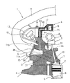
図1は、内燃機関の要部縦断面構成図である。
内燃機関1は、シリンダブロック2上にシリンダヘッド3が設けられ、シリンダヘッド3の上面にシリンダヘッドカバー4が設けられている。
シリンダブロック2に形成されたシリンダボア5内にはピストン6が設けられ、シリンダヘッド3内の動弁室S内には、カムシャフト8で回転されるカム9により開閉動される吸気弁7が設けられ、吸気弁7により燃焼室C上面の吸気ポート10が開閉されるように構成されている。
Next, the best mode for carrying out the present invention will be described using examples.
FIG. 1 is a longitudinal sectional configuration diagram of a main part of an internal combustion engine.
In the
A
図2は、シリンダヘッド3の詳細を示す平面図であり、図3は、シリンダヘッド3の詳細を示す正面図である。
シリンダヘッド3には、図1乃至図3に示すように、一端が吸気ポート10を介して燃焼室Cに開口し、他端がインテークマニホールド取付け面3dに開口する吸気通路21(21A,21B,21C,21D)が気筒列方向に間隔をおいて4個形成されており、インテークマニホールド取付け面3dにガスケットGを介してインテークマニホールド11の取付けフランジ部11aが取り付けられて、インテークマニホールド11と吸気ポート10が吸気通路21を介して連通されている。
なお、図1中12は燃料管であり、13は燃料管12を保護する保護カバーである。
FIG. 2 is a plan view showing details of the
As shown in FIGS. 1 to 3, the
In FIG. 1, 12 is a fuel pipe, and 13 is a protective cover for protecting the
シリンダヘッド3の各吸気通路21A,21B,21C,21D内には、図3に示すように、タンブルプレート24が設けられ、このタンブルプレート24により各吸気通路21A,21B,21C,21D内は、上側の上通路21aと下側の下通路21bとに区画されている。ここで、タンブルプレート24は、燃焼室Cへの吸気の流動状態を、例えばタンブル流やスワール流のような状態に変化させることができるものであり、上通路21aは常に吸気が流れる通路として機能するものである。
As shown in FIG. 3, a
シリンダヘッド3のインテークマニホールド取付け面3dには、インテークマニホールド取付け面3d側が開口する3個の鋳抜き孔(鋳抜き空間)25a,25b,25cが形成されている。
ここで、鋳抜き孔(鋳抜き空間)25a,25b,25cを各吸気通路21A,21B,21C,21D間に形成するのは、一般に構造上肉厚となる各吸気通路21A,21B,21C,21D間の肉厚を薄肉化して、鋳造成形時に形成される収縮巣の発生を抑制するめである。このため、鋳抜き孔(鋳抜き空間)25a,25b,25cは、比較的大きな容量に形成される。
また、インテークマニホールド取付け面3dには、吸気通路21A,21Bそれぞれの上通路21aと鋳抜き孔25aとを連通する連通凹部26が形成されているとともに、吸気通路21C,21Dそれぞれの上通路21aと鋳抜き孔25cとを連通する連通凹部26が形成されている。即ち、連通凹部26,26は、鋳抜き孔25aを挟む両側の吸気通路21A,21Bの両方と鋳抜き孔25aとを連通するとともに、鋳抜き孔25cを挟む両側の吸気通路21C,21Dの両方と鋳抜き孔25cとを連通する。
Three intake holes (casting spaces) 25a, 25b, and 25c are formed in the intake
Here, the reason why the punched holes (casting spaces) 25a, 25b, 25c are formed between the
The intake
また、シリンダヘッド3には、図2および図3に示すように、シリンダヘッドカバー取付け面3aから鋳抜き孔25a,25cまで貫通する貫通孔22,22が形成されているとともに、シリンダヘッドカバー4を取付け固定するためのボルトBが螺合するボルト孔3bが複数個形成されている。なお、インテークマニホールド取付け面3d側のシリンダヘッドカバー取付け面3aには、吸気通路21A,21B間および吸気通路21C,21D間に対応する位置2箇所に外方に突出する突出壁部3c,3cが形成されており、複数のボルト孔3bのうちの2個がこの膨出壁部3cに形成されている。
As shown in FIGS. 2 and 3, the
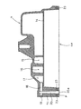
図4は、シリンダヘッドカバー4の内部を示す断面図であり、図5は、シリンダヘッドカバー4の内部構造の詳細を拡大して示す拡大図である。
シリンダヘッドカバー4には、図4および図5に示すように、新気が流れる新気導入通路15と、ブローバイガス中の油分を分離可能な気液分離部16と、気液分離されたブローバイガスが流れるブローバイガス主通路17とが形成されており、下面にバッフルプレート14が取り付けられることにより、それぞれが区画されるとともに図示しない動弁機構が配置される動弁室Sから隔離される。
新気導入通路15と気液分離部16とブローバイガス主通路17とは、図4および図5に示すように、シリンダヘッドカバー4の中央部から気筒列方向に沿う側壁側に向かって新気導入通路15,気液分離部16,ブローバイガス主通路17の順に形成されている。シリンダヘッドカバー4は、ブローバイガス主通路17が隣接するシリンダヘッドカバー4の気筒列方向に沿う側壁がシリンダヘッド3のインテークマニホールド取付け面3d側となるように、ボルト孔4bからボルトBを挿通してボルト孔3bに螺合することによりシリンダヘッド3に取り付けられる。なお、シリンダヘッド3のシリンダヘッドカバー取付け面3aとシリンダヘッドカバー4のシリンダヘッド取付け面4aとの間にはガスケット23が介在している。なお、気液分離部16は、図5に示すように、蛇行状に形成された部分や容積が拡大された部分を有する。
FIG. 4 is a cross-sectional view showing the inside of the cylinder head cover 4, and FIG. 5 is an enlarged view showing the details of the internal structure of the cylinder head cover 4.
As shown in FIGS. 4 and 5, the cylinder head cover 4 includes a fresh
As shown in FIGS. 4 and 5, the fresh
シリンダヘッドカバー4のインテークマニホールド取付け面3d側となる側壁には、膨出壁部3c,3cに対応する膨出壁部4c,4cが形成されており、膨出壁部4c,4cには、膨出壁部4c,4c外周面からブローバイガス主通路17まで貫通する連通孔18,18が形成されている。なお、各連通孔18,18の膨出壁部4c,4c外周面側は、栓19により塞がれている。また、膨出壁部4c,4cには、連通孔18,18から膨出壁部4c,4cのシリンダヘッド取付け面4a側まで達する流路20,20が形成されている。この流路20,20は、シリンダヘッドカバー4がシリンダヘッド3に取り付けられた際に、シリンダヘッド3に形成された貫通孔22,22に連通接続する。
On the side wall of the cylinder head cover 4 on the intake
次に、このような構造の内燃機関1の作用を説明する。
シリンダボア5とピストン6との隙間から図示しないクランクケース内に流出するブローバイガスは、シリンダヘッド3内を通り、シリンダヘッドカバー4の気液分離部16に流入される。
この気液分離部16内に流入したブローバイガスは、気液分離部16の蛇行した部分や容積が拡大した部分において良好に油分が分離される。
油分が分離されたブローバイガスは、ブローバイガス主通路17から連通孔18を通り、さらに流路(ブローバイガス導入路)20からシリンダヘッド3の貫通孔(ブローバイガス還流路)22内を流下し、鋳抜き孔25a,25c内に流入する。
鋳抜き孔25a,25c内に流入したブローバイガスは、左右方向に延びる連通凹部26から左右側のそれぞれの吸気通路21A,21B,21C,21Dの上通路21a内に流入し、各気筒の吸気ポート10に還流されるものである。
Next, the operation of the
Blow-by gas that flows into a crankcase (not shown) from the gap between the cylinder bore 5 and the
The blow-by gas that has flowed into the gas-
The blow-by gas from which the oil component has been separated flows from the blow-by gas
The blow-by gas that has flowed into the punched
このように、比較的大きな容量で形成された鋳抜き孔(鋳抜き空間)25a,25cにブローバイガスを流入することにより、図示しないクランクケース内の圧力脈動を十分に吸収できる。この結果、ブローバイガスを安定的かつ均等化して吸気ポート10に供給できる。しかも、製品の品質向上のために設けた鋳抜き孔(鋳抜き空間)25a,25cを用いるから、別途、圧力脈動を吸収するための部位を設ける必要がない。この結果、ブローバイガスを安定的かつ均等化して供給し得る構造を効率よく確保することができる。
In this manner, by blowing blow-by gas into the casting holes (casting spaces) 25a and 25c formed with a relatively large capacity, pressure pulsations in a crankcase (not shown) can be sufficiently absorbed. As a result, the blow-by gas can be supplied to the
また、シリンダヘッド3のインテークマニホールド取付け面3dに、鋳抜き孔(鋳抜き空間)25a,25b,25cと連通凹部26,26を形成するだけであるから、鋳抜き孔(鋳抜き空間)25a,25cに流入するブローバイガスを吸気通路21A,21B,21C,21D側に還流する構造を簡易に確保することができる。
さらに、燃焼室Cへの吸気流動状態を例えば、タンブル流やスワール流のような状態に変化できるように、各吸気通路21A,21B,21C,21Dが複数の通路21a,21bに区画できるように形成されている場合であっても、常に吸気が流れる通路21aと鋳抜き孔(鋳抜き空間)25a,25cとを連通できるからブローバイガスを常に還流することができるものとなる。
Further, since the intake
Further, the
なお、上記実施例では、連通凹部26,26は、インテークマニホールド11を取り付けるシリンダヘッド3のインテークマニホールド取付け面3dに形成するものとしたが、インテークマニホールド11の取付けフランジ部11aに形成するものとしても構わない。
In the above embodiment, the communication recesses 26, 26 are formed on the intake
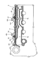
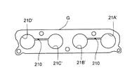
図6は、鋳抜き孔25a,25c近傍の断面を拡大して示す拡大断面図であり、図7は、ガスケットGの概略を示す構成図であり、図8は、インテークマニホールド11の取付けフランジ部11aを拡大して示す拡大図である。
図示するように、インテークマニホールド11の取付けフランジ部11aに連通凹部180,180を形成するとともに、ガスケットGに吸気通路21Aと吸気通路21Bとに対応する開口21A’,21B’を接続する接続開口210および吸気通路21Cと吸気通路21Dとに対応する開口21C’,21D’を接続する接続開口210を形成するものとすれば良い。
また、インテークマニホールド取付け面3dや取付けフランジ部11aには連通凹部26,26,180,180は設けず、ガスケットGに接続開口210,210だけを設けるものとしたり、インテークマニホールド取付け面3dや取付けフランジ部11aの両方に連通凹部26,26,180,180を設けるとともにガスケットGに接続開口210,210を設けるものとしても構わない。
FIG. 6 is an enlarged cross-sectional view showing an enlarged cross section in the vicinity of the cast holes 25a and 25c, FIG. 7 is a configuration diagram showing an outline of the gasket G, and FIG. 8 is a mounting flange portion of the
As shown in the drawing, the communication recesses 180 and 180 are formed in the mounting
Further, the intake
実施例では、連通凹部26,26は、吸気通路21A,21Bおよび吸気通路21C,21Dのそれぞれの上通路21a,21aと鋳抜き孔25a,25cとを連通するように形成するものとしたが、連通凹部26,26は、吸気通路21A,21Bおよび吸気通路21C,21Dのそれぞれの下通路21b,21bと鋳抜き孔25a,25cとを連通するように形成するものとしても差し支えない。この場合、下通路21b,21bに吸気が流れるときにだけブローバイガスを還流するよう制御するものとしても良い。
In the embodiment, the communication recesses 26 and 26 are formed so as to communicate the
また、実施例では、気液分離部16は、シリンダヘッドカバー4内に形成されるものとしたが、気液分離部16は、シリンダヘッドカバー4とは別に気液分離装置として設けるものとしても構わない。
In the embodiment, the gas-
以上、本発明の実施の形態について実施例を用いて説明したが、本発明はこうした実施例に限定されるものではなく、本発明の要旨を逸脱しない範囲内において、種々なる形態で実施し得ることは勿論である。 As mentioned above, although embodiment of this invention was described using the Example, this invention is not limited to such an Example, In the range which does not deviate from the summary of this invention, it can implement with a various form. Of course.
1 内燃機関
2 シリンダブロック
3 シリンダヘッド
3d インテークマニホールド取付け面
4 シリンダヘッドカバー
5 シリンダボア
6 ピストン
7 吸気弁
10 吸気ポート
11 インテークマニホールド
11a 取付けフランジ部
16 気液分離部
17 ブローバイガス主通路
18 連通孔
20 流路(ブローバイガス導入路)
20a 開口部
21,21A,21B,21C,21D 吸気通路
21a 上通路
21b 下通路
21A’,21B’,21C’,21D’ 開口
22 貫通孔(ブローバイガス還流路)
24 タンブルプレート
25a,25b,25c 鋳抜き孔(鋳抜き空間)
26,180 連通凹部
210 接続開口
G ガスケット
DESCRIPTION OF
24
26,180
Claims (6)
前記シリンダヘッドの前記複数の吸気通路間に前記インテークマニホールド取付け面側が開口する鋳抜き空間を形成し、該鋳抜き空間を介して前記ブローバイガスを前記吸気通路に還流してなる
ブローバイガス還流構造。 A blow-by gas recirculation structure for recirculating blow-by gas to a plurality of intake passages formed in a cylinder head having one end opened to the combustion chamber via the intake port and the other end opened to the intake manifold mounting surface;
A blow-by gas recirculation structure in which a casting space in which the intake manifold mounting surface side opens is formed between the plurality of intake passages of the cylinder head, and the blow-by gas is returned to the intake passage through the casting space.
前記連通凹部は、前記複数の通路のうち常に吸気が供給される通路と前記鋳抜き空間とを連通してなる請求項2または請求項3に記載のブローバイガス還流構造。 The intake passage is formed to be capable of partitioning a plurality of passages so that an intake flow state to the combustion chamber can be changed.
4. The blow-by gas recirculation structure according to claim 2, wherein the communication recess communicates a passage through which the intake air is constantly supplied and the cast-out space among the plurality of passages.
該シリンダヘッドカバーは、内部に前記ブローバイガス中の油分を分離可能な気液分離部が設けられるとともに、該気液分離部に連通する連通部と、前記シリンダヘッドへの取付け面側に開口する開口部とを有する流路が形成されてなり、
前記シリンダヘッドは、一端が前記開口部を介して前記流路に連通するとともに他端が前記鋳抜き空間に連通する貫通孔が形成されてなり、
前記気液分離部から前記流路に導入された前記ブローバイガスを前記貫通孔から前記鋳抜き空間を介して前記吸気通路に還流してなる請求項1乃至請求項4何れかに記載のブローバイガス還流構造。 A cylinder head cover is attached to the cylinder head,
The cylinder head cover is provided therein with a gas-liquid separation part capable of separating oil in the blow-by gas, a communication part communicating with the gas-liquid separation part, and an opening opened on the mounting surface side to the cylinder head A flow path having a portion is formed,
The cylinder head is formed with a through hole having one end communicating with the flow path through the opening and the other end communicating with the casting space.
5. The blow-by gas according to claim 1, wherein the blow-by gas introduced into the flow path from the gas-liquid separation unit is returned to the intake passage from the through hole through the casting space. Reflux structure.
内燃機関。 An internal combustion engine in which the blowby gas flowing out from the gap between the piston and the cylinder bore is recirculated to the intake side by the blowby gas recirculation structure according to any one of claims 1 to 5.
Priority Applications (5)
| Application Number | Priority Date | Filing Date | Title |
|---|---|---|---|
| JP2008152335A JP5235512B2 (en) | 2008-06-10 | 2008-06-10 | Blowby gas recirculation structure and internal combustion engine |
| US12/388,160 US8079350B2 (en) | 2008-06-10 | 2009-02-18 | Blow-by gas recirculation structure for internal combustion engine |
| EP09002536.2A EP2133521B1 (en) | 2008-06-10 | 2009-02-23 | Blow-by gas recirculation structure for internal combustion engine |
| CN200910203669XA CN101603480B (en) | 2008-06-10 | 2009-06-09 | Blow-by gas recirculation structure and internal combustion engine |
| KR1020090050733A KR101471211B1 (en) | 2008-06-10 | 2009-06-09 | Blow-by gas reflux structure and internal combustion engine |
Applications Claiming Priority (1)
| Application Number | Priority Date | Filing Date | Title |
|---|---|---|---|
| JP2008152335A JP5235512B2 (en) | 2008-06-10 | 2008-06-10 | Blowby gas recirculation structure and internal combustion engine |
Publications (2)
| Publication Number | Publication Date |
|---|---|
| JP2009299512A true JP2009299512A (en) | 2009-12-24 |
| JP5235512B2 JP5235512B2 (en) | 2013-07-10 |
Family
ID=40717113
Family Applications (1)
| Application Number | Title | Priority Date | Filing Date |
|---|---|---|---|
| JP2008152335A Expired - Fee Related JP5235512B2 (en) | 2008-06-10 | 2008-06-10 | Blowby gas recirculation structure and internal combustion engine |
Country Status (5)
| Country | Link |
|---|---|
| US (1) | US8079350B2 (en) |
| EP (1) | EP2133521B1 (en) |
| JP (1) | JP5235512B2 (en) |
| KR (1) | KR101471211B1 (en) |
| CN (1) | CN101603480B (en) |
Cited By (4)
| Publication number | Priority date | Publication date | Assignee | Title |
|---|---|---|---|---|
| JP2012117451A (en) * | 2010-11-30 | 2012-06-21 | Daihatsu Motor Co Ltd | Pcv structure |
| JP2013113108A (en) * | 2011-11-25 | 2013-06-10 | Honda Motor Co Ltd | Blow-by path structure for internal combustion engine |
| WO2016111021A1 (en) * | 2015-01-06 | 2016-07-14 | 愛知機械工業株式会社 | Cylinder head, internal combustion engine equipped with same, and cylinder head manufacturing method |
| JP2020109265A (en) * | 2018-12-31 | 2020-07-16 | 株式会社クボタ | Cylinder head cover |
Families Citing this family (8)
| Publication number | Priority date | Publication date | Assignee | Title |
|---|---|---|---|---|
| JP4697271B2 (en) * | 2008-07-16 | 2011-06-08 | トヨタ自動車株式会社 | Cylinder head structure of internal combustion engine |
| FR2958335B1 (en) * | 2010-03-31 | 2013-03-15 | Peugeot Citroen Automobiles Sa | CYLINDER HEAD INCORPORATING A RECYCLED MOTOR GAS DISTRIBUTOR |
| JP2012097675A (en) * | 2010-11-02 | 2012-05-24 | Aisin Seiki Co Ltd | Intake system of internal combustion engine |
| JP6250893B2 (en) * | 2015-02-13 | 2017-12-20 | トヨタ自動車株式会社 | Blowby gas treatment device and intake manifold |
| CN107061075B (en) * | 2017-05-09 | 2019-12-31 | 安徽江淮汽车集团股份有限公司 | Air intake manifold assembly |
| KR101977340B1 (en) | 2017-12-13 | 2019-05-13 | 지엠 글로벌 테크놀러지 오퍼레이션스 엘엘씨 | Internally integrated positive crankcase ventilation system for combustion engine |
| FR3082241B1 (en) | 2018-06-08 | 2020-11-20 | Renault Sas | INTAKE DISTRIBUTOR FOR IC ENGINE WITH RECIRCULATED GAS MIXING DEVICE |
| CN120140051B (en) * | 2025-03-28 | 2025-11-21 | 长城汽车股份有限公司 | Cylinder head assembly and engine |
Citations (12)
| Publication number | Priority date | Publication date | Assignee | Title |
|---|---|---|---|---|
| JPH0237104A (en) * | 1988-07-28 | 1990-02-07 | Mazda Motor Corp | Blow-by gas processor of engine |
| JPH0530412U (en) * | 1991-09-21 | 1993-04-23 | マツダ株式会社 | Blow-by gas recirculation system for engines |
| JPH0717912U (en) * | 1993-09-08 | 1995-03-31 | ダイハツ工業株式会社 | Blow-by gas passage structure |
| DE19920195A1 (en) * | 1999-05-03 | 2000-11-16 | Audi Ag | Inlet manifold for injection IC engine has an intermediate manifold with integral mounting for the injectors and with outer ports onto which is fitted the inlet manifold |
| JP2003027955A (en) * | 2001-07-17 | 2003-01-29 | Honda Motor Co Ltd | V-type engine |
| JP2004245148A (en) * | 2003-02-14 | 2004-09-02 | Aichi Mach Ind Co Ltd | Blowby gas recirculation device for internal combustion engine |
| DE10320493A1 (en) * | 2003-05-08 | 2004-12-02 | Volkswagen Ag | Combustion engine with crankcase ventilation has head cover ports connected to oil separator inlet, outlet so blow-by gas flows from crankcase via hollow chamber, oil separator to clean air path |
| JP2005076487A (en) * | 2003-08-29 | 2005-03-24 | Suzuki Motor Corp | Cylinder head of multi-cylinder engine |
| JP2005113847A (en) * | 2003-10-10 | 2005-04-28 | Nissan Motor Co Ltd | Intake device for internal combustion engine |
| JP2005155454A (en) * | 2003-11-26 | 2005-06-16 | Honda Motor Co Ltd | Blow-by gas reduction device |
| US20050235972A1 (en) * | 2004-04-20 | 2005-10-27 | Yi Jea W | Exhaust gas recirculation (EGR) system |
| DE102006038831A1 (en) * | 2006-08-18 | 2008-02-21 | Volkswagen Ag | Internal combustion engine, has separation compartment, which is arranged in flow process after crank case, which is connected with collection chamber by channel |
Family Cites Families (5)
| Publication number | Priority date | Publication date | Assignee | Title |
|---|---|---|---|---|
| US3839996A (en) * | 1970-08-14 | 1974-10-08 | Automotive Eng Res Inc | Internal combustion engine with closed crankcase and intake valve cover operating under vacuum |
| DE19907398A1 (en) * | 1999-02-20 | 2000-08-31 | Volkswagen Ag | Air intake system for an internal combustion engine |
| JP2002155721A (en) * | 2000-11-20 | 2002-05-31 | Sanshin Ind Co Ltd | Freezer in propulsion device for small boat |
| JP2003232210A (en) * | 2002-02-08 | 2003-08-22 | Kawasaki Heavy Ind Ltd | Engine breather device |
| JP2008152335A (en) | 2006-12-14 | 2008-07-03 | Ntt Comware Corp | Moving direction detection system, moving direction detection method, moving direction detection program |
-
2008
- 2008-06-10 JP JP2008152335A patent/JP5235512B2/en not_active Expired - Fee Related
-
2009
- 2009-02-18 US US12/388,160 patent/US8079350B2/en not_active Expired - Fee Related
- 2009-02-23 EP EP09002536.2A patent/EP2133521B1/en not_active Ceased
- 2009-06-09 KR KR1020090050733A patent/KR101471211B1/en not_active Expired - Fee Related
- 2009-06-09 CN CN200910203669XA patent/CN101603480B/en not_active Expired - Fee Related
Patent Citations (12)
| Publication number | Priority date | Publication date | Assignee | Title |
|---|---|---|---|---|
| JPH0237104A (en) * | 1988-07-28 | 1990-02-07 | Mazda Motor Corp | Blow-by gas processor of engine |
| JPH0530412U (en) * | 1991-09-21 | 1993-04-23 | マツダ株式会社 | Blow-by gas recirculation system for engines |
| JPH0717912U (en) * | 1993-09-08 | 1995-03-31 | ダイハツ工業株式会社 | Blow-by gas passage structure |
| DE19920195A1 (en) * | 1999-05-03 | 2000-11-16 | Audi Ag | Inlet manifold for injection IC engine has an intermediate manifold with integral mounting for the injectors and with outer ports onto which is fitted the inlet manifold |
| JP2003027955A (en) * | 2001-07-17 | 2003-01-29 | Honda Motor Co Ltd | V-type engine |
| JP2004245148A (en) * | 2003-02-14 | 2004-09-02 | Aichi Mach Ind Co Ltd | Blowby gas recirculation device for internal combustion engine |
| DE10320493A1 (en) * | 2003-05-08 | 2004-12-02 | Volkswagen Ag | Combustion engine with crankcase ventilation has head cover ports connected to oil separator inlet, outlet so blow-by gas flows from crankcase via hollow chamber, oil separator to clean air path |
| JP2005076487A (en) * | 2003-08-29 | 2005-03-24 | Suzuki Motor Corp | Cylinder head of multi-cylinder engine |
| JP2005113847A (en) * | 2003-10-10 | 2005-04-28 | Nissan Motor Co Ltd | Intake device for internal combustion engine |
| JP2005155454A (en) * | 2003-11-26 | 2005-06-16 | Honda Motor Co Ltd | Blow-by gas reduction device |
| US20050235972A1 (en) * | 2004-04-20 | 2005-10-27 | Yi Jea W | Exhaust gas recirculation (EGR) system |
| DE102006038831A1 (en) * | 2006-08-18 | 2008-02-21 | Volkswagen Ag | Internal combustion engine, has separation compartment, which is arranged in flow process after crank case, which is connected with collection chamber by channel |
Cited By (6)
| Publication number | Priority date | Publication date | Assignee | Title |
|---|---|---|---|---|
| JP2012117451A (en) * | 2010-11-30 | 2012-06-21 | Daihatsu Motor Co Ltd | Pcv structure |
| JP2013113108A (en) * | 2011-11-25 | 2013-06-10 | Honda Motor Co Ltd | Blow-by path structure for internal combustion engine |
| WO2016111021A1 (en) * | 2015-01-06 | 2016-07-14 | 愛知機械工業株式会社 | Cylinder head, internal combustion engine equipped with same, and cylinder head manufacturing method |
| JPWO2016111021A1 (en) * | 2015-01-06 | 2017-10-19 | 愛知機械工業株式会社 | Cylinder head, internal combustion engine equipped with the same, and method of manufacturing cylinder head |
| JP2020109265A (en) * | 2018-12-31 | 2020-07-16 | 株式会社クボタ | Cylinder head cover |
| JP7063802B2 (en) | 2018-12-31 | 2022-05-09 | 株式会社クボタ | Cylinder head cover |
Also Published As
| Publication number | Publication date |
|---|---|
| JP5235512B2 (en) | 2013-07-10 |
| KR20090128332A (en) | 2009-12-15 |
| US20090301448A1 (en) | 2009-12-10 |
| EP2133521A2 (en) | 2009-12-16 |
| KR101471211B1 (en) | 2014-12-09 |
| US8079350B2 (en) | 2011-12-20 |
| CN101603480A (en) | 2009-12-16 |
| EP2133521A3 (en) | 2011-03-30 |
| EP2133521B1 (en) | 2017-03-22 |
| CN101603480B (en) | 2012-12-19 |
Similar Documents
| Publication | Publication Date | Title |
|---|---|---|
| JP5235512B2 (en) | Blowby gas recirculation structure and internal combustion engine | |
| CN101680350B (en) | liquid cooled internal combustion engine | |
| US10107171B2 (en) | Cooling structure of internal combustion engine | |
| JP6299737B2 (en) | Multi-cylinder engine cooling structure | |
| JP4923036B2 (en) | Exhaust gas recirculation device for internal combustion engine | |
| US20130118433A1 (en) | Intake system | |
| CN101307714A (en) | Water jacket structure of water-cooled internal combustion engine | |
| JP4225327B2 (en) | Oil return structure for internal combustion engine | |
| JP6384492B2 (en) | Multi-cylinder engine cooling structure | |
| JP4788236B2 (en) | Cylinder head cooling structure | |
| KR20180094795A (en) | Cylinder head | |
| JP2007051601A5 (en) | ||
| CN110107421B (en) | In-vehicle internal combustion engine | |
| JP6314966B2 (en) | Multi-cylinder engine cooling structure | |
| JP6062312B2 (en) | Cylinder block cooling structure | |
| KR102682341B1 (en) | Cooling jacket and cylinder head including the same | |
| JP2007138823A (en) | Internal combustion engine | |
| JP2011236849A (en) | Exhaust cooling system of internal combustion engine and exhaust cooling adapter | |
| JP2008057360A (en) | Engine exhaust gas recirculation system | |
| JP6835574B2 (en) | Cylinder block and internal combustion engine equipped with it | |
| JP4036185B2 (en) | Engine oil separator | |
| JP4954113B2 (en) | Blowby gas recirculation structure and internal combustion engine having the same | |
| JP2008057359A (en) | Engine exhaust gas recirculation system | |
| JP2016125465A (en) | Cylinder head | |
| JP2005155454A (en) | Blow-by gas reduction device |
Legal Events
| Date | Code | Title | Description |
|---|---|---|---|
| A621 | Written request for application examination |
Free format text: JAPANESE INTERMEDIATE CODE: A621 Effective date: 20110307 |
|
| A131 | Notification of reasons for refusal |
Free format text: JAPANESE INTERMEDIATE CODE: A131 Effective date: 20120207 |
|
| A977 | Report on retrieval |
Free format text: JAPANESE INTERMEDIATE CODE: A971007 Effective date: 20120209 |
|
| A521 | Written amendment |
Free format text: JAPANESE INTERMEDIATE CODE: A523 Effective date: 20120308 |
|
| A131 | Notification of reasons for refusal |
Free format text: JAPANESE INTERMEDIATE CODE: A131 Effective date: 20120925 |
|
| A521 | Written amendment |
Free format text: JAPANESE INTERMEDIATE CODE: A523 Effective date: 20121119 |
|
| TRDD | Decision of grant or rejection written | ||
| A01 | Written decision to grant a patent or to grant a registration (utility model) |
Free format text: JAPANESE INTERMEDIATE CODE: A01 Effective date: 20130305 |
|
| A61 | First payment of annual fees (during grant procedure) |
Free format text: JAPANESE INTERMEDIATE CODE: A61 Effective date: 20130326 |
|
| R150 | Certificate of patent or registration of utility model |
Free format text: JAPANESE INTERMEDIATE CODE: R150 Ref document number: 5235512 Country of ref document: JP Free format text: JAPANESE INTERMEDIATE CODE: R150 |
|
| FPAY | Renewal fee payment (event date is renewal date of database) |
Free format text: PAYMENT UNTIL: 20160405 Year of fee payment: 3 |
|
| LAPS | Cancellation because of no payment of annual fees |