JP2009299528A - Turbomachine - Google Patents
Turbomachine Download PDFInfo
- Publication number
- JP2009299528A JP2009299528A JP2008153016A JP2008153016A JP2009299528A JP 2009299528 A JP2009299528 A JP 2009299528A JP 2008153016 A JP2008153016 A JP 2008153016A JP 2008153016 A JP2008153016 A JP 2008153016A JP 2009299528 A JP2009299528 A JP 2009299528A
- Authority
- JP
- Japan
- Prior art keywords
- variable
- mounting angle
- blade
- blades
- rotor
- Prior art date
- Legal status (The legal status is an assumption and is not a legal conclusion. Google has not performed a legal analysis and makes no representation as to the accuracy of the status listed.)
- Pending
Links
Images


Landscapes
- Control Of Turbines (AREA)
- Turbine Rotor Nozzle Sealing (AREA)
- Structures Of Non-Positive Displacement Pumps (AREA)
Abstract
【課題】ターボ機械での定格負荷運転時の流体性能の低下を防止すると共に、部分回転速度運転時での静翼の後流に起因する動翼への振動応力を低減する。
【解決手段】ターボ機械は、複数の径方向に伸びた動翼をその外周に有するロータと、前記ロータを、その内部に回転自由に保持すると共に、流体を当該ロータの動翼に導くための流路を形成するケーシングと、前記ケーシングに形成された前記流路内において、その円周方向に分布して複数配置され、かつ、部分回転速度運転時にはその取付角が変更可能な可変静翼を供えており、前記可変静翼は、前記ケーシングの円周方向において一様に分布しており、かつ、部分回転速度運転時における取付角の変更量が円周方向に非一様である。
【選択図】図2[PROBLEMS] To prevent a decrease in fluid performance during rated load operation in a turbo machine and to reduce vibration stress on a moving blade caused by a wake of a stationary blade during partial rotation speed operation.
A turbomachine has a rotor having a plurality of radially extending rotor blades on its outer periphery, and the rotor is rotatably held in the rotor and fluid is guided to the rotor blades of the rotor. A casing that forms a flow path, and a variable stationary blade that is distributed in the circumferential direction in the flow path formed in the casing and that can change its mounting angle during partial rotation speed operation. The variable stator vanes are uniformly distributed in the circumferential direction of the casing, and the amount of change in the mounting angle during the partial rotation speed operation is non-uniform in the circumferential direction.
[Selection] Figure 2
Description
本発明は、例えば、圧縮機やタービンなどにおいて利用されるターボ機械に係り、特に、部分回転速度運転時における可変静翼後流の変動流体力による動翼の共振破壊防止に好適な構造のターボ機械に関する。 The present invention relates to a turbo machine used in, for example, a compressor or a turbine, and more particularly, a turbo having a structure suitable for preventing resonance destruction of a moving blade due to fluctuating fluid force of a variable stationary blade wake during partial rotation speed operation. Related to machinery.
一般に、ターボ機械は、回転する動翼を有するロータと、当該ロータを回転自由に保持し、もって、その間に流体の流路を形成する、所謂、ケーシング7とにより構成されている。また、例えば、圧縮機における静圧回復やタービンにおける流れの加速などを目的として、ケーシングの流路内において、その円周方向に一定間隔で静翼が配置される構造が採用されることがある。更に、部分回転速度運転時や部分負荷運転時においては、ターボ機械の出力特性や流路特性などが不平衡となるため、ターボ機械の出力特性を調整することを目的として、その運転時に、上記静翼の取付角度を変更とした、所謂、可変静翼を採用するものも既に知られている。
In general, a turbomachine is composed of a rotor having rotating rotor blades and a so-called
なお、かかる可変静翼の構造としては、例えば、以下の特許文献1、特に、その図4に開示されており、この従来の可変静翼の構造では、駆動リングを回転させることにより、取付角変更アームを介して駆動リングに結合された当該可変静翼の取付角を変更することが可能となっている。
The structure of such a variable stator blade is disclosed, for example, in
ところで、一般に、静翼の下流側では、当該静翼が存在する部分と存在しない部分とでは、その流れの特性が異なり、そして、上流側に当該静翼が存在する部分の流れを「後流」と呼ぶ。この静翼の下流側に配置された回転する動翼は、「後流」を繰り返し通過することから、当該動翼の回転周波数と静翼枚数との積で表される周波数の流体加振力によって加振される。そして、この加振周波数と動翼の固有振動数が一致した場合、所謂、共振により動翼に過大な変動応力が発生し、そのため、動翼が疲労破壊してしまう可能性がある。従来では、かかる動翼の疲労破壊を防止するために、定格回転速度における加振周波数と動翼の固有振動数を離調させる、所謂、共振回避設計が行われている。しかしながら、当該加振周波数はロータの回転速度に比例して変化するため、部分回転速度運転時における共振を全て回避することは困難である。 By the way, in general, on the downstream side of the stationary blade, the flow characteristics are different between the portion where the stationary blade is present and the portion where the stationary blade is not present. " Since the rotating moving blade disposed downstream of the stationary blade repeatedly passes through the “wake”, a fluid exciting force having a frequency represented by the product of the rotational frequency of the moving blade and the number of stationary blades. Is excited by. When the excitation frequency and the natural frequency of the moving blade coincide with each other, excessive fluctuation stress is generated in the moving blade due to so-called resonance, so that the moving blade may be fatigued. Conventionally, so-called resonance avoidance design has been performed in which the vibration frequency at the rated rotational speed and the natural frequency of the moving blade are detuned in order to prevent fatigue failure of the moving blade. However, since the excitation frequency changes in proportion to the rotational speed of the rotor, it is difficult to avoid all resonances during partial rotational speed operation.
そこで、かかる共振時には、一定周期の流体加振力を受けることによって振動応力が増大してしまうことから、静翼の円周方向ピッチを非一様(不均一)とすることにより流体加振力の周期を分散させ、もって、動翼の共振応力低減する構造が、以下の特許文献2の図3に開示されている。
Therefore, at the time of such resonance, vibration stress increases by receiving a fluid excitation force of a fixed period, so the fluid excitation force can be increased by making the circumferential pitch of the stationary blades non-uniform (non-uniform). FIG. 3 of
しかしながら、上記の従来技術によれば、例えば、円周方向に一定間隔で静翼を配置すると、上述したように、部分回転速度運転時における静翼の「後流」による流体加振力との共振により、動翼に過大な振動応力が発生する可能性がある。これに対し、上述したように、静翼の円周方向ピッチを非一様(不均一)にすることによれば、共振時の動翼振動応力を低減することはできるが、しかしながら、定格負荷運転時の流体性能が低下する可能性がある。 However, according to the above-described prior art, for example, when the stationary blades are arranged at regular intervals in the circumferential direction, as described above, the fluid excitation force due to the “wake” of the stationary blades during partial rotational speed operation. Due to the resonance, excessive vibration stress may be generated in the rotor blade. On the other hand, as described above, by making the circumferential pitch of the stationary blades non-uniform (non-uniform), it is possible to reduce the blade vibration stress at the time of resonance. Fluid performance during operation may be reduced.
そこで、本発明は、上述した従来技術における問題点に鑑みてなされたものであり、その目的は、部分回転速度運転時の可変静翼後流に起因する流体加振力との共振による動翼の振動応力を低減する共に、定格負荷運転時の流体性能低下をも防止すること可能な構造を備えてターボ機械を提供することにある。 Accordingly, the present invention has been made in view of the above-described problems in the prior art, and the purpose thereof is a moving blade by resonance with a fluid excitation force caused by a variable stationary blade wake at the time of partial rotation speed operation. It is another object of the present invention to provide a turbomachine having a structure capable of reducing the vibration stress and preventing a decrease in fluid performance during rated load operation.
上記の目的を達成するため、本発明では、まず、複数の径方向に伸びた動翼をその外周に有するロータと、前記ロータを、その内部に回転自由に保持すると共に、流体を当該ロータの動翼に導くための流路を形成するケーシングと、前記ケーシングに形成された前記流路内において、その円周方向に分布して複数配置され、かつ、部分回転速度運転時にはその取付角が変更可能な可変静翼を有するターボ機械において、前記可変静翼は、前記ケーシングの円周方向において一様に分布しており、かつ、部分回転速度運転時における取付角の変更量が円周方向に非一様であるターボ機械が提供される。 In order to achieve the above-described object, in the present invention, first, a rotor having a plurality of radially extending moving blades on its outer periphery, the rotor is rotatably held therein, and a fluid is supplied to the rotor. A casing that forms a flow path for guiding the moving blades, and a plurality of distributions are arranged in the circumferential direction in the flow path formed in the casing, and the mounting angle is changed during partial rotation speed operation. In a turbomachine having a variable vane capable of being distributed, the variable vane is uniformly distributed in the circumferential direction of the casing, and the amount of change in the mounting angle during partial rotational speed operation is circumferential. A turbomachine that is non-uniform is provided.
また、本発明によれば、前記に記載したターボ機械において、前記可変静翼の取付角の変更量が、複数の隣接する可変静翼を対として、それぞれ、異なっていることが好ましく、更には、前記可変静翼の取付角の変更量が、2枚の隣接する可変静翼を対として、それぞれ、異なっていることが好ましい。また、本発明では、前記可変静翼の取付角の変更量が、正弦波状に変化していることが、又は、ランダムに変化していることが好ましい。 Further, according to the present invention, in the turbo machine described above, it is preferable that the amount of change in the mounting angle of the variable stationary blade is different for each pair of adjacent variable stationary blades, It is preferable that the amount of change in the mounting angle of the variable vane is different for each pair of two adjacent variable vanes. Moreover, in this invention, it is preferable that the change amount of the attachment angle of the said variable stator blade is changing to the shape of a sine wave, or changing at random.
加えて、本発明では、前記に記載したターボ機械において、前記可変静翼は、更に、当該可変静翼に固定したピニオンギアと、当該ピニオンギアとかみ合いながら円周方向に揺動することにより前記可変静翼の取付角を制御する複数の駆動ラックとを有しており、もって、前記複数の駆動ラックは、それぞれ、異なる前記可変静翼の取付角を制御することが好ましく、又は、前記可変静翼は、更に、当該可変静翼に固定した前記ピニオンギアと、当該ピニオンギアとかみ合いながら円周方向に揺動することにより前記可変静翼の取付角を制御する駆動ラックとを有しており、もって、当該駆動ラックはそれぞれ異なる前記可変静翼の取付角を制御することが好ましい。更には、前記に記載したターボ機械において、前記可変静翼は、更に、当該可変静翼に固定した取付角制御アームと、当該取付角制御アームを円周方向に拘束し、かつ、円周方向に揺動することにより前記可変静翼の取付角を制御する駆動リングを有しており、さらに、前記取付角制御アームにおける前記可変静翼側固定点と前記駆動リング側拘束点との間の距離が円周方向の各静翼に対して非一様であることが好ましい。 In addition, according to the present invention, in the turbo machine described above, the variable stationary blade further includes a pinion gear fixed to the variable stationary blade and a rocking motion in a circumferential direction while meshing with the pinion gear. A plurality of drive racks for controlling the mounting angles of the variable stator blades, and each of the plurality of drive racks preferably controls a different mounting angle of the variable stator blades. The stationary blade further includes the pinion gear fixed to the variable stationary blade, and a drive rack that controls the mounting angle of the variable stationary blade by swinging in the circumferential direction while meshing with the pinion gear. Therefore, it is preferable that the drive racks control the mounting angles of the variable stator blades different from each other. Further, in the turbo machine described above, the variable stator blade further includes an attachment angle control arm fixed to the variable stator blade, a restraint of the attachment angle control arm in the circumferential direction, and a circumferential direction. And a drive ring that controls the mounting angle of the variable stator blades by swinging in the direction, and further, a distance between the variable stator blade side fixed point and the drive ring side restraint point in the mounting angle control arm Is preferably non-uniform for each stationary vane in the circumferential direction.
以上に述べた本発明によれば、ターボ機械において、可変静翼の取付角の変更量が円周方向に非一様であることにより、可変静翼の取付角変更時(部分回転速度運転時)において、可変静翼の取付角が非一様となり、下流側の動翼部において静翼後流の円周方向ピッチが非一様となるため、動翼に作用する流体加振力の周期を分散することから、動翼の共振応力を低減することができる。他方、定格負荷運転時には、可変静翼の取付角を一様な状態に戻すことができるため、可変静翼の取付角が非一様になることによる定格負荷運転時の流体性能低下を防止することができる。 According to the present invention described above, in the turbomachine, the change amount of the mounting angle of the variable stator blade is non-uniform in the circumferential direction, so that the mounting angle of the variable stator blade is changed (at the time of partial rotation speed operation). ), The mounting angle of the variable stator blades is non-uniform, and the circumferential pitch of the stator vane wake flow is non-uniform in the downstream blade section, so the period of fluid excitation force acting on the rotor blades Is distributed, the resonance stress of the rotor blade can be reduced. On the other hand, during rated load operation, the mounting angle of the variable stator blades can be returned to a uniform state, thus preventing fluid performance degradation during rated load operation due to non-uniform mounting angles of the variable stator blades. be able to.
以下、本発明を実施するための最良の形態について、実施例1及び2として、添付の図面を参照しながら説明する。 Hereinafter, the best mode for carrying out the present invention will be described as first and second embodiments with reference to the accompanying drawings.
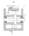
まず、本発明の実施例1になるターボ機械1の内部構造を、その縦断面により、添付の図1に示す。
First, the internal structure of the
図にも示すように、本実施例1のターボ機械1は、その途中に径方向に伸びた動翼3を複数有する棒状のロータ4と、当該ロータ4をその両端に設けた軸受5を介して内部に回転自由に保持し、かつ、その一部、特に、その外周(前記ロータ4の動翼3の部分)に流体(図中の矢印を参照)を流すための円筒状の流路6を形成したケーシング7とから構成されている。そして、当該ケーシング7の流路6の内においては、上記ロータ4の動翼3の上流において、複数の可変静翼8が円周方向に一様(均等、一定間隔)に分布して配置されており、かつ、各可変静翼8は、その運転時において、その取付角を自由に変更することが出来るようになっている。
As shown in the drawing, the
即ち、各可変静翼8の一端から伸びた取付ロッド9が設けられており、当該取付ロッド9を介して、ケーシング7に対して揺動自由に取り付けられている。なお、図中における符号10a、11、12、13は、以下にもその詳細を述べるが、上記可変静翼8の取付角を制御するための機構である、可変静翼取付角制御機構を構成する要素を示している。
That is, an
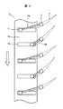
続いて、上記図1にその全体構成を示した本実施例1になるターボ機械1における上記可変静翼取付角制御機構2の外観を、添付の図2に示す。なお、この図2は、上記ターボ機械1の外周面において、特に、上記可変静翼8が取り付けられた近傍の一部を、湾曲面から平面に展開して示した図である。
Subsequently, the external appearance of the variable stator blade mounting
この図2にも示すように、各可変静翼8の一端から伸びた取付ロッド9の先端には、取付角制御アーム10aの一端が固定され、更に、当該取付角制御アーム10aの他端には、結合ピン11が固定されている。そして、当該結合ピン11を、上記ターボ機械1の外周面に沿って移動可能に設けられた(図の矢印を参照)駆動リング12に形成された結合スリット13内に挿入することにより、当該ピン11と駆動リング12とが、円周方向に、一体となって揺動可能になっている。
As shown in FIG. 2, one end of the mounting
即ち、上述した可変静翼取付角制御機構2の構成によれば、駆動リング12を円周方向に移動させることにより(図の矢印を参照)、結合ピン11の上記取付ロッド9に対する位置(角度)を変更し、もって、結合ピン11がその一端に固定された可変静翼8の取付角が変化するようになっている(図中の破線を参照)。
That is, according to the configuration of the variable stator blade mounting
なお、この図2に示した例では、可変静翼8の一枚おきに長い取付角制御アーム10aと短い取付角制御アーム10bとが用いられている。これによれば、取付角制御アーム10a、10bの可変静翼8側における固定点(即ち、取付ロッド9の位置)と、その駆動リング12側における拘束点(即ち、結合ピン11の位置であり、駆動リング12に形成された結合スリット13内の位置)との間の距離が非一様(不均一:但し、この場合には、隣接する可変静翼の一対毎に、一枚おきに異なる)となり、駆動リング12を円周方向に移動(揺動)させたときの可変静翼8の取付角の変更量は、長い取付角制御アーム10aを用いた可変静翼8では小さく、他方、短い取付角制御アーム10bを用いた可変静翼8では大きくなる。即ち、この図では、駆動リング12を移動(揺動)させたとき、可変静翼8の取付角が可変静翼8の一枚おきに異なるものとなることがわかる。
In the example shown in FIG. 2, a long mounting
更に、添付の図3には、上記ターボ機械1における可変静翼取付角制御機構2の他の例を示す。この例では、可変静翼8の一枚おきに、それぞれ、その長さが異なる(即ち、ランダムな)取付角制御アーム10a、10b…が用いられている。即ち、これによれば、駆動リング12を円周方向に移動(揺動)させたときの可変静翼8の取付角の変更量を、それぞれ、一枚毎に異なるようにすることが出来る。又は、ここでは図示しないが、上述した取付角制御アーム10a、10b…の長さを、例えば、正弦波状など、所望のパターンにより設定することも可能である。なお、その場合には、駆動リング12を円周方向に移動(揺動)させたときの可変静翼8の取付角の変更量を、正弦波状など、所望のパターンにすることが可能となる。
Further, FIG. 3 attached herewith shows another example of the variable stator blade mounting
以上にその詳細を説明した可変静翼取付角制御機構2を備えたターボ機械1では、その部分回転速度運転時や部分負荷運転時においては、駆動リング12を円周方向に移動(揺動)させ、もって、上記ロータ4の動翼3の上流に位置する可変静翼8の取付角を変更するが、その際、上述した可変静翼取付角制御機構2によれば、ケーシング7の流路6の内において配置された複数の可変静翼8は、その円周方向に一様(均等)に分布しているが、しかしながら、当該可変静翼8の取付角の変更量が円周方向に非一様(不均一)であることから、その下流側に位置するロータ4の動翼3においては、当該静翼8により生じる「後流」の円周方向ピッチが非一様(不均一)となるため、当該動翼3に作用する流体加振力の周期を分散することができ、もって、動翼の共振応力を低減することが可能となる。
In the
他方、定格負荷運転時においては、ケーシング7の流路6の内においてその円周方向に一様(均等)に分布して配置された複数の可変静翼8を、その取付角が一様な状態に戻すことができることから、当該静翼8による流体性能の低下を防止することが出来る。即ち、部分回転速度運転時の可変静翼後流に起因する流体加振力との共振による動翼の振動応力を低減する共に、定格負荷運転時の流体性能低下をも防止することが可能となる。
On the other hand, during the rated load operation, a plurality of variable
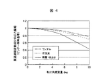
ここで、添付の図4のグラフは、上述した可変静翼取付角制御機構2を備えたターボ機械1における、特に、部分回転速度運転時や部分負荷運転時における効果を確認するため、取付角制御アーム10a、10b…の長さを、「ランダム(図3を参照)」、「正弦波」、「静翼1枚おき(図2を参照)」に設定した場合における、上流側可変静翼8を通過して動翼3に作用する周波数成分の圧力振幅「翼通過周波数成分の圧力振幅」(但し、ピッチ(静翼8の単位変化量)が一様の場合を基準とする)の変化(縦軸)を示している。なお、横軸には、上記駆動リング12を円周方向に移動(揺動)させたときの可変静翼8の取付角の変更量「取付角変更量」が示されている。
Here, the attached graph of FIG. 4 shows the mounting angle in order to confirm the effect of the
図4のグラフからも明らかなように、ピッチ誤差(静翼8の単位変化のパターン)を円周方向に「ランダム(図3を参照)」に分布させた結果、「正弦波状」に分布させた結果、及び、「静翼1枚おき(図2を参照)」に変化させた結果を示している。いずれのピッチ誤差分布においても、その「取付角変更量」(最大ピッチ誤差)を大きくすると、流体加振力を低減できることがわかる。また、特に、互いに隣接する一対の静翼8において「静翼一枚おき」にそのピッチ誤差を変化させるパターンによる流体加振力低減効果が、最も高いことがわかる。
As is apparent from the graph of FIG. 4, the pitch error (pattern of unit change of the stationary blade 8) is distributed “randomly (see FIG. 3)” in the circumferential direction. And the result of changing every other vane (see FIG. 2). In any pitch error distribution, it can be seen that the fluid excitation force can be reduced by increasing the “mounting angle change amount” (maximum pitch error). In particular, it can be seen that the effect of reducing the fluid excitation force by the pattern of changing the pitch error of every other stationary blade in a pair of
以上のように、本実施例1になるターボ機械1によれば、可変静翼に固定した取付角制御アームと駆動リングとを用いて可変静翼の取付角を制御し、かつ、取付角制御アームにおける可変静翼側固定点と駆動リング側拘束点との間の距離を円周方向の各可変静翼に対して非一様(不均一)となるようにしたことにより、各可変静翼の取付角の変更量を任意に設定できることから、上述した効果が、より確実に得られることとなる。
As described above, according to the
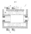
次に、添付の図5には、本発明のターボ機械1の他の例である、実施例2をその断面により示す。本実施例2では、可変静翼8の取付ロッド9には、上述した取付角制御アーム10a、10b…に代えて、ピニオンギア14を固定し、更に、当該ピニオンギア14と対向する面にギアを形成し、かつ、当該ピニオンギア14とかみ合いながら円周方向に揺動(移動)することにより、上記可変静翼8の各々の取付角を制御するための複数(本例では、2本)の駆動ラック15a、15bが設けられている。
Next, FIG. 5 attached herewith shows a second embodiment, which is another example of the
そして、図の上部に示すピニオンギア14aは、内周側の駆動ラック15aと、そして、下部に示すピニオンギア14bは、外周側の駆動ラック15bと、それぞれ、かみ合っている。かかる構成によれば、2本の駆動ラック15の揺動(移動)量が異なるように制御することにより、各可変静翼8(但し、隣接する一対の静翼)の取付角の変更量を、上記2本の駆動ラック15毎に異なるよう制御することが出来る。駆動ラック15の揺動制御方法としては、各駆動ラック15に対し、独立のアクチュエータを取り付けることにより、個別に制御しても良く、あるいは、例えば、ここでは図示しないリンク機構などを用いることにより、個々の駆動ラック15の揺動量を変更しても良い。
The
また、図示のように、上述したピニオンギア14a、14bと複数(本例では、2本)の駆動ラック15a、15bを、上記ケーシング7の軸方向(図の横方向)に複数設けることによれば、径方向に複数伸びた動翼3を複数段有するロータ4に対しても、各段の動翼3に対して、その取付角の変更量が非一様(不均一)な静翼8を、比較的容易に、設けることが出来る。また、上述した駆動ラック15a、15bを2本に限らず、更に多くの駆動ラックを設けることによれば、隣接する一対の静翼の取付角だけに限られず、より多くの数の動翼3の取付角の変更量を、個別に制御することが可能となることは、当業者であれば明らかであろう。
Further, as shown in the figure, the above-described
このように、本発明の実施例2になるターボ機械1では、可変静翼8に固定されたピニオンギアピニオンギア14a、14bと、これらにかみ合う複数の駆動ラック15a、15bが、それぞれ、異なる可変静翼8(但し、隣接する一対の静翼)の取付角を制御し、もって、取付角の変更量を駆動ラック毎に異ならせることによれば、上記の実施例1と同様に、可変静翼8の取付角を非一様に制御できるため、上記と同様の効果が得られる。
As described above, in the
更に、添付の図6には、本発明のターボ機械1の他の例である、実施例3の断面を示す。図からも明らかなように、本実施例3においては、最上流側(図の左側)の可変静翼8では、1本の駆動リング12中には、2本の駆動ラック15c、15dが設けられており、それ故、駆動リング12の回転に伴うこれら2本のラック15c、15dの揺動角は、同一となっている。なお、より具体的には、図の可変静翼8において、その上方の可変静翼8には、そのピッチ円直径の大きいピニオンギア14cが、他方、その下部の可変静翼8には、そのピッチ円直径の小さいピニオンギア14dが、それぞれ、固定されている。そのため、上記駆動リング12の回転に伴う駆動ラック15c、15dの揺動時において、複数の可変静翼8の取付角の変化量が異なることとなる。なお、この実施例3では、駆動リング12が1本であることから、駆動ラック15の揺動制御機構が単純化できるという効果がある。また、上記のように、複数の駆動ラックの揺動角を共通とし、ピニオンギアのピッチ円直径をかみ合う駆動ラック毎に変更したことにより、簡易な構造で上記と同様の効果が得られる。
Further, FIG. 6 attached herewith shows a cross section of
なお、以上には、本発明を実施するための最良の形態として、上記の実施例1〜3について述べたが、本発明では、これらに限定されることなく、例えば、動翼3と静翼8との組で表される段の数は、上記図1のように1段であっても、又は、上記図5や図6に示すように、複数段であっても良い。 In the above description, the first to third embodiments have been described as the best mode for carrying out the present invention. However, the present invention is not limited to these examples. The number of stages represented by a set of 8 may be one stage as shown in FIG. 1 or a plurality of stages as shown in FIGS.
また、上記の図5に示すように、可変静翼8の全てに、本発明の構造を適用しても良く、又は、上記の図5にも示すように、動翼の共振が特に問題となる一部の段の可変静翼8のみに、本発明の構造を適用して良い。なお、一部の段の可変静翼8に本発明の構造を適用する場合は、当該適用する段の位置は任意である。また、上述した取付角の変更量の分布パターンは、上記図2にも示すように、隣接する一対の静翼8の1本おきとしても良く、又は、上記図3にも示すように、その他の任意の分布パターンとしても良い。加えて、上記の図5では2本の駆動リングを、また、上記の図6では2種類のピニオンギアを用いたが、これらは3又はそれ以上の種類のピニオンギアを用いても良い。
Further, as shown in FIG. 5 above, the structure of the present invention may be applied to all of the variable
1…ターボ機械、2…可変静翼取付角制御機構、3…動翼、4…ロータ、5…軸受、6…流路、7…ケーシング7、8…可変静翼、9…取付ロッド、10a、10b…取付角制御アーム、11…結合ピン、12…駆動リング、13…結合スリット、14a、15b…ピニオンギア、15a、15b…駆動ラック。
DESCRIPTION OF
Claims (8)
前記ロータを、その内部に回転自由に保持すると共に、流体を当該ロータの動翼に導くための流路を形成するケーシングと、
前記ケーシングに形成された前記流路内において、その円周方向に分布して複数配置され、かつ、部分回転速度運転時にはその取付角が変更可能な可変静翼を有するターボ機械において、
前記可変静翼は、前記ケーシングの円周方向において一様に分布しており、かつ、部分回転速度運転時における取付角の変更量が円周方向に非一様であることを特徴とするターボ機械。 A rotor having a plurality of radially extending blades on its outer periphery;
A casing that rotatably holds the rotor therein and that forms a flow path for guiding fluid to the rotor blades of the rotor;
In the turbo machine having a variable stationary blade that is arranged in the circumferential direction in the flow path formed in the casing and is variable in its mounting angle during partial rotation speed operation.
The variable stationary blades are uniformly distributed in a circumferential direction of the casing, and a change amount of a mounting angle at the time of partial rotational speed operation is nonuniform in the circumferential direction. machine.
Priority Applications (1)
| Application Number | Priority Date | Filing Date | Title |
|---|---|---|---|
| JP2008153016A JP2009299528A (en) | 2008-06-11 | 2008-06-11 | Turbomachine |
Applications Claiming Priority (1)
| Application Number | Priority Date | Filing Date | Title |
|---|---|---|---|
| JP2008153016A JP2009299528A (en) | 2008-06-11 | 2008-06-11 | Turbomachine |
Publications (1)
| Publication Number | Publication Date |
|---|---|
| JP2009299528A true JP2009299528A (en) | 2009-12-24 |
Family
ID=41546675
Family Applications (1)
| Application Number | Title | Priority Date | Filing Date |
|---|---|---|---|
| JP2008153016A Pending JP2009299528A (en) | 2008-06-11 | 2008-06-11 | Turbomachine |
Country Status (1)
| Country | Link |
|---|---|
| JP (1) | JP2009299528A (en) |
Cited By (4)
| Publication number | Priority date | Publication date | Assignee | Title |
|---|---|---|---|---|
| JP2022170197A (en) * | 2021-04-28 | 2022-11-10 | 三菱重工業株式会社 | rotary machine |
| JP2023047723A (en) * | 2021-09-27 | 2023-04-06 | 株式会社Ihi | turbine |
| CN118273980A (en) * | 2024-04-30 | 2024-07-02 | 中国科学院工程热物理研究所 | Compressor stator blade adjustment method and compressor |
| CN120042659A (en) * | 2025-04-24 | 2025-05-27 | 上海慕帆动力科技有限公司 | Stator blade device in steam turbine and steam turbine |
-
2008
- 2008-06-11 JP JP2008153016A patent/JP2009299528A/en active Pending
Cited By (6)
| Publication number | Priority date | Publication date | Assignee | Title |
|---|---|---|---|---|
| JP2022170197A (en) * | 2021-04-28 | 2022-11-10 | 三菱重工業株式会社 | rotary machine |
| JP7614932B2 (en) | 2021-04-28 | 2025-01-16 | 三菱重工業株式会社 | Rotating Machinery |
| JP2023047723A (en) * | 2021-09-27 | 2023-04-06 | 株式会社Ihi | turbine |
| JP7686522B2 (en) | 2021-09-27 | 2025-06-02 | 株式会社Ihi | Turbine |
| CN118273980A (en) * | 2024-04-30 | 2024-07-02 | 中国科学院工程热物理研究所 | Compressor stator blade adjustment method and compressor |
| CN120042659A (en) * | 2025-04-24 | 2025-05-27 | 上海慕帆动力科技有限公司 | Stator blade device in steam turbine and steam turbine |
Similar Documents
| Publication | Publication Date | Title |
|---|---|---|
| JP6022565B2 (en) | Gas turbine engine for aircraft engine | |
| JP5965609B2 (en) | Rotating machine with spacers for fluid dynamics control | |
| JP5055208B2 (en) | Variable stator vane driving method and apparatus for axial flow compressor | |
| JP4981399B2 (en) | Method for forming non-uniform stator vane spacing in a compressor | |
| US10584591B2 (en) | Rotor with subset of blades having a cutout leading edge | |
| US20090263057A1 (en) | Bearing damper element, bearing, and gas turbine engine | |
| JP5681384B2 (en) | Rotor blade for turbine engine | |
| JP5931274B2 (en) | Bushing for torque frame of gas turbine engine fan drive gear unit | |
| AU2014228703B2 (en) | Vane arrangement having alternating vanes with different trailing edge profile | |
| WO2014052209A1 (en) | Pylon matched fan exit guide vane for noise reduction in a geared turbofan engine | |
| JP6896894B2 (en) | Bearing attenuator elements, bearings and compressor elements provided with such bearing attenuator elements, and methods of manufacturing such bearing attenuator elements. | |
| JP2009299528A (en) | Turbomachine | |
| JP2017115873A (en) | Turbomachine and turbine nozzle therefor | |
| CA2791971A1 (en) | Non-uniform variable vanes | |
| US6174129B1 (en) | Turbine vane clocking mechanism and method of assembling a turbine having such a mechanism | |
| JP5494972B2 (en) | Axial-flow turbomachine and its modification method | |
| EP3109451B1 (en) | Gear system for high bypass ratio geared turbofan engine | |
| JP2015519501A (en) | Stator blade ring and design method of stator blade ring for axial flow fluid machine | |
| JPS59150903A (en) | Blade arrangement of rotary machine | |
| EP3296573A1 (en) | A technique for controlling rotating stall in compressor for a gas turbine engine | |
| EP3477120A1 (en) | Gas turbine engine control method and system | |
| JP2014525547A (en) | Francis turbine or Francis pump or Francis pump turbine | |
| JP6749746B2 (en) | Steam turbine with resonant chamber | |
| US10677266B1 (en) | Gas turbine engine airfoil frequency design | |
| JP6811141B2 (en) | Turbine vane row |