JP2009299538A - Control device for internal combustion engine - Google Patents
Control device for internal combustion engine Download PDFInfo
- Publication number
- JP2009299538A JP2009299538A JP2008153392A JP2008153392A JP2009299538A JP 2009299538 A JP2009299538 A JP 2009299538A JP 2008153392 A JP2008153392 A JP 2008153392A JP 2008153392 A JP2008153392 A JP 2008153392A JP 2009299538 A JP2009299538 A JP 2009299538A
- Authority
- JP
- Japan
- Prior art keywords
- internal combustion
- combustion engine
- temperature
- exhaust gas
- gas sensor
- Prior art date
- Legal status (The legal status is an assumption and is not a legal conclusion. Google has not performed a legal analysis and makes no representation as to the accuracy of the status listed.)
- Granted
Links
Images


Landscapes
- Testing Of Engines (AREA)
- Combined Controls Of Internal Combustion Engines (AREA)
Abstract
【課題】内燃機関の始動時における排気ガスセンサの被水による素子割れを抑制しつつ内燃機関の始動時からエミッションを低減できる内燃機関の制御装置を提供する。
【解決手段】内燃機関のシリンダ内で圧縮された空気の圧縮熱により排気系の温度を上昇させるために、内燃機関の始動前にクランクシャフトを回転駆動し、排気ガスセンサの周りの温度が排気ガスに含まれる水蒸気を凝結させない非凝結温度に達したかを判断し、排気ガスセンサの周りの温度が非凝結温度に達したと判断した後に、ヒータを起動させ、ヒータの起動後に内燃機関にシリンダへ燃料を供給して始動させる、構成とした。
【選択図】図3A control device for an internal combustion engine that can reduce emissions from the start of the internal combustion engine while suppressing element cracking due to flooding of an exhaust gas sensor at the start of the internal combustion engine.
In order to raise the temperature of the exhaust system by the compression heat of the air compressed in the cylinder of the internal combustion engine, the crankshaft is rotationally driven before starting the internal combustion engine, and the temperature around the exhaust gas sensor is the exhaust gas. It is determined whether the non-condensing temperature that does not condense the water vapor contained in the exhaust gas sensor has been reached, and after determining that the temperature around the exhaust gas sensor has reached the non-condensing temperature, the heater is started. It was set as the structure which supplies and starts fuel.
[Selection] Figure 3
Description
本発明は、内燃機関の制御装置に関する。 The present invention relates to a control device for an internal combustion engine.
内燃機関の排気系には、例えば、酸素センサや空燃比センサ等の排気ガスセンサが取り付けられている。この排気ガスセンサは、エンジン始動直後からヒータへの通電により暖機されるが、排気ガスに含まれる水蒸気が凝縮して温度上昇した排気ガスセンサに付着すると素子割れが発生する可能性がある。 For example, an exhaust gas sensor such as an oxygen sensor or an air-fuel ratio sensor is attached to the exhaust system of the internal combustion engine. Although this exhaust gas sensor is warmed up by energizing the heater immediately after the engine is started, if the water vapor contained in the exhaust gas condenses and adheres to the exhaust gas sensor whose temperature has risen, element cracking may occur.
このため、例えば、特許文献1は、エンジンの始動時の冷却水温が設定温度に到達したところで、排気ガスセンサに内蔵されたヒータへの通電を開始し、外気温が外気温判定値より低い場合には上記設定温度を高くし、エンジン始動時の冷却水温と外気温度の差が大きい場合には、上記設定温度をさらに高くする。また、排気系に取り付けられた排気ガスセンサ周辺の水(液体)が存在しなくなるまで、ヒータへの通電開始を遅らせるという、排気ガスセンサの被水対策を実施している。
For this reason, for example,
ところで、エンジンが始動後に排気管内の凝縮水(液体)が存在しなくなるまで排気ガスセンサのヒータへの通電開始時期を遅らせると、排気ガスセンサの検出信号に基くフィードバック制御の開始時期が大幅に遅延し、エミッションの放出量が増加するという問題がある。具体的には、排気ガスセンサのヒータへの通電開始が遅れると、触媒の前に設けられた空燃比センサや触媒の後方に設けられた酸素センサの活性化が遅れ、排気ガスセンサに基づく空燃比フィードバック補正制御の開始が遅れ、空燃比のずれを修正できずにエミッションの排出量が基準値からはずれてしまう。 By the way, if the start of energizing the heater of the exhaust gas sensor is delayed until the condensed water (liquid) in the exhaust pipe does not exist after the engine is started, the start time of feedback control based on the detection signal of the exhaust gas sensor is greatly delayed. There is a problem that the amount of emission is increased. Specifically, if the start of energization of the heater of the exhaust gas sensor is delayed, the activation of the air-fuel ratio sensor provided in front of the catalyst or the oxygen sensor provided behind the catalyst is delayed, and air-fuel ratio feedback based on the exhaust gas sensor The start of the correction control is delayed, and the deviation of the air-fuel ratio cannot be corrected, and the emission amount deviates from the reference value.
本発明は、上記の事情に鑑みて成されたものであり、その目的とするところは、内燃機関の始動時における排気ガスセンサの被水による素子割れを抑制しつつ内燃機関の始動時からエミッションを低減できる内燃機関の制御装置を提供することにある。 The present invention has been made in view of the above circumstances, and an object of the present invention is to reduce emissions from the start of the internal combustion engine while suppressing element cracking due to moisture in the exhaust gas sensor at the start of the internal combustion engine. An object of the present invention is to provide a control device for an internal combustion engine that can be reduced.
本発明に係る内燃機関の制御装置は、排気系に設けられた排気ガスセンサと、前記排気ガスセンサを活性化するためのヒータとを備える内燃機関の制御装置であって、内燃機関のシリンダ内で圧縮された空気の圧縮熱により前記排気系の温度を上昇させるために、内燃機関の始動前にクランクシャフトを回転駆動するモータリング手段と、前記排気ガスセンサの周りの温度が排気ガスに含まれる水蒸気を凝結させない非凝結温度に達したかを判断する判断手段と、前記排気ガスセンサの周りの温度が前記非凝結温度に達したと判断した後に、前記ヒータを起動させるヒータ起動手段と、を有する。 An internal combustion engine control apparatus according to the present invention is an internal combustion engine control apparatus including an exhaust gas sensor provided in an exhaust system and a heater for activating the exhaust gas sensor, and is compressed in a cylinder of the internal combustion engine. In order to raise the temperature of the exhaust system due to the compressed heat of the compressed air, motoring means for rotationally driving the crankshaft before the internal combustion engine is started, and the temperature around the exhaust gas sensor is the water vapor contained in the exhaust gas. Determining means for determining whether a non-condensing temperature that does not condense has been reached, and heater starting means for starting the heater after determining that the temperature around the exhaust gas sensor has reached the non-condensing temperature.
上記構成において、前記ヒータの起動後に内燃機関にシリンダへ燃料を供給して始動させる制御手段をさらに有する構成を採用できる。 In the above-described configuration, it is possible to employ a configuration that further includes control means for starting the heater by supplying fuel to the cylinder after starting the heater.
上記構成において、前記モータリング手段により前記クランクシャフトを回転駆動させる際に、前記圧縮熱の効率が最も高くなるように、内燃機関のシリンダ内への流入空気量を制御する制御手段をさらに有する構成を採用できる。 In the above-described configuration, there is further provided control means for controlling the amount of air flowing into the cylinder of the internal combustion engine so that the efficiency of the compression heat is maximized when the crankshaft is rotationally driven by the motoring means. Can be adopted.
上記構成において、前記内燃機関は、内燃機関その吸気バルブ及び排気バルブの開閉タイミングが可変な可変バルブタイミング機構を備え、前記モータリング手段による前記クランクシャフトの回転駆動中に吸気バルブを閉鎖させる制御手段をさらに有する構成を採用できる。 In the above configuration, the internal combustion engine includes a variable valve timing mechanism in which opening and closing timings of the intake valve and the exhaust valve of the internal combustion engine are variable, and a control unit that closes the intake valve during the rotational driving of the crankshaft by the motoring unit A configuration further having
上記構成において、前記内燃機関は、内燃機関その吸気バルブ及び排気バルブの開閉タイミングが可変な可変バルブタイミング機構を備え、前記モータリング手段による前記クランクシャフトの回転駆動中に、シリンダ内の圧縮熱効率が高まるように吸気弁バルブ及び排気バルブの開閉タイミングを制御する制御手段をさらに有する構成を採用できる。 In the above configuration, the internal combustion engine includes a variable valve timing mechanism in which the opening and closing timings of the intake valve and the exhaust valve of the internal combustion engine are variable, and the compression heat efficiency in the cylinder is increased during the rotational driving of the crankshaft by the motoring means. A configuration that further includes control means for controlling the opening and closing timings of the intake valve and the exhaust valve so as to increase can be adopted.
上記構成において、前記判断手段は、内燃機関の吸気系の吸入空気量と圧縮熱とに基いて、前記排気ガスセンサの周りの温度が前記非凝結温度に達したかを判断する構成を採用できる。 In the above-described configuration, the determination unit may determine whether the temperature around the exhaust gas sensor has reached the non-condensing temperature based on the intake air amount and compression heat of the intake system of the internal combustion engine.
上記構成において、前記判断手段は、内燃機関の始動前の冷却水温度と始動後の冷却水温度とに基づいて、前記排気ガスセンサの周りの温度が前記非凝結温度に達したかを判断する構成を採用できる。 In the above configuration, the determination means determines whether the temperature around the exhaust gas sensor has reached the non-condensing temperature based on the coolant temperature before starting the internal combustion engine and the coolant temperature after starting. Can be adopted.
上記構成において、前記判断手段は、内燃機関の始動前の潤滑油温度と始動後の潤滑油温度とに基づいて、前記排気ガスセンサの周りの温度が前記非凝結温度に達したかを判断する構成を採用できる。 In the above configuration, the determination means determines whether the temperature around the exhaust gas sensor has reached the non-condensing temperature based on the lubricating oil temperature before starting the internal combustion engine and the lubricating oil temperature after starting. Can be adopted.
上記構成において、前記判断手段は、外部環境条件に応じて、前記非凝結温度の高さを調節する構成を採用できる。 The said structure can employ | adopt the structure which adjusts the height of the said non-condensing temperature according to external environmental conditions in the said structure.
本発明によれば、内燃機関の始動時における排気ガスセンサの被水による素子割れを抑制しつつ内燃機関の始動時からエミッションを低減できる。 According to the present invention, it is possible to reduce emissions from the time of starting the internal combustion engine while suppressing element cracking due to the flooding of the exhaust gas sensor at the time of starting the internal combustion engine.
以下、本発明の最良の実施形態について、添付図面を参照しつつ説明する。 DESCRIPTION OF EXEMPLARY EMBODIMENTS Embodiments of the invention will be described below with reference to the accompanying drawings.
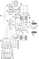
図1は本発明の内燃機関の制御装置が適用される車両の一例としてハイブリット車両の概略構成図、及び、図2は図1の車両の内燃機関(以下、エンジンともいう。)の概略構成図である。 FIG. 1 is a schematic configuration diagram of a hybrid vehicle as an example of a vehicle to which a control device for an internal combustion engine of the present invention is applied. FIG. 2 is a schematic configuration diagram of an internal combustion engine (hereinafter also referred to as an engine) of the vehicle of FIG. It is.
この車両20は、エンジン22、エンジン用電子制御ユニット(エンジンECU)24、クランキング手段としてのモータ/ジェネレータMG1、モータ/ジェネレータMG2、動力分配統合機構30、減速ギア35、モータ電子制御ユニット(モータECU)40、インバータ41,42、バッテリ50、ギア機構60、ハイブリッド用電子制御ユニット(ECU)70等を備えている。
The
エンジン22は、そのクランクシャフト26がダンパ28を介して動力分配統合機構30のキャリア34に連結されている。
The
動力分配統合機構30は、モータ/ジェネレータMG1のロータと連結されたサンギア31、サンギア31の外周に同心状に配置されると共に減速ギア35の出力側と連結されたリングギア32、サンギア31とリングギア32とに噛合いするピニオンギア33、ピニオンギア33を保持するキャリア34等から構成され、リングギア32に連結されたリングギア軸32aは、減速ギア35の出力側に接続されていると共に、ギア機構60の入力ギヤに連結されている。
The power distribution and
モータ/ジェネレータMG2は、そのロータが減速ギアの入力側に接続されている。 The rotor of motor / generator MG2 is connected to the input side of the reduction gear.
エンジン22の出力軸であるクランクシャフト26の回転は、モータ/ジェネレータMG1及びギヤ機構60及びディファレンシャルギア62を介して駆動輪63a,63bに分配されるようになっている。
The rotation of the
また、モータ/ジェネレータMG2の回転は、減速機35を介してリングギア軸32aに出力され、ギア機構60及びディファレンシャルギア62を介して駆動輪63a,63bに入力可能になっている。
The rotation of the motor / generator MG2 is output to the
インバータ41,42は、バッテリ50の直流を3相交流に変換してモータ/ジェネレータMG1、MG2にそれぞれ供給すると共に、モータ/ジェネレータMG1,MG2で発電された3相交流を直流に変換してバッテリ50へ供給できるようになっている。
モータECU40は、モータ/ジェネレータMG1,MG2にそれぞれ設けられた回転位置検出センサ43,44からの信号に基づいて、インバータ41,42を駆動し、モータ/ジェネレータMG1,MG2を回転制御する。
Motor ECU 40
バッテリ50は、モータ/ジェネレータMG1で発電された電力を蓄え、発進時、加速時、登坂時等にモータ/ジェネレータMG2へ電力を供給し、減速時にモータ/ジェネレータMG2で回生発電した電力を蓄える。バッテリ50は、200ボルト程度の電圧で電力の供給及び充電を行う。
The
バッテリECU52は、バッテリ50に設けられた温度センサ51からの信号等に基づいて、バッテリ50の充電状態の監視を行う。
The
サブバッテリ53は、補機類や後述するVVT150を駆動する電力を供給する。このサブバッテリ53は、バッテリECU52よりも低電圧であり、例えば、12V程度である。
The
ハイブリットECU70は、CPU72、ROM74、RAM76等のハードウエアと所要のソフトウエアで構成され、イグニションスイッチ80、シフトレバー81に設けられたシフトポジションセンサ82、アクセルペダル83に設けられたアクセルポジションセンサ84、ブレーキペダル85に設けられたブレーキペダルセンサ86、車速センサ88等からの信号が入力され、運転状態に応じたエンジン22の出力及びモータトルクを求め、各ECUへ要求値を出力することにより、駆動力を制御する等の機能を備えている。また、空燃比センサ100、酸素センサ200、図示しないクランクポジションセンサ、エンジンの冷却水の温度を検出する水温センサ250、カムポジションセンサ260、スロットルバルブポジションセンサ270、エアフローメータ280、エンジンオイルの温度を検出する温度センサ290等からの信号が入力され、始動時及び走行中における各種制御を総合的に管理する。なお、ハイブリッドECU70は、モータリング手段、判断手段、ヒータ起動手段等を構成する。
The hybrid ECU 70 includes hardware such as a
エンジン22は、図示しないが、シリンダブロックに形成された燃焼室の内部で燃料および空気の混合気を燃焼させ、燃焼室内でピストンを往復移動させることにより動力を発生する。本実施形態では、エンジン22は、火花点火式内燃機関、より具体的にはガソリンエンジンである。
Although not shown, the
エンジン22のシリンダヘッドには、吸気ポートを開閉する吸気弁と、排気ポートを開閉する排気弁とが気筒ごとに配設され、各吸気弁および各排気弁はカムシャフトによって開閉させられる。また、シリンダヘッドの頂部には、燃焼室内の混合気に点火するための点火プラグが気筒ごとに取り付けられている。
In the cylinder head of the
さらに、吸気通路、特に吸気ポート内に燃料を噴射するインジェクタ(燃料噴射弁)が気筒ごとに配設される。インジェクタから噴射された燃料は吸入空気と混合されて混合気をなし、この混合気が吸気弁の開弁時に燃焼室に吸入され、ピストンで圧縮され、点火プラグで点火燃焼させられる。 Further, an injector (fuel injection valve) for injecting fuel into the intake passage, particularly the intake port, is provided for each cylinder. The fuel injected from the injector is mixed with intake air to form an air-fuel mixture. The air-fuel mixture is sucked into the combustion chamber when the intake valve is opened, compressed by the piston, and ignited and burned by the spark plug.
図2に示すように、エンジン22の各気筒の排気ポートの下流側には排気管22Eが接続されており、排気管22Eには、二つの触媒23A及び23Bが離隔して取り付けられている。触媒23Aの上流側には排気ガスの空燃比を検出するための空燃比センサ100が設けられ、触媒23Bの下流側には排気ガス中の酸素濃度を検出する酸素センサ200が設けられている。空燃比センサ100及び酸素センサ200は、これらを活性化するためのヒータを内蔵している。
As shown in FIG. 2, an
シリンダヘッド上には、可変バルブタイミング機構(VVT)150が設けられている。VVT150は、吸気バルブ側および排気バルブ側のカムシャフトの位相をエンジンECU24からの指令に応じて可変する。
A variable valve timing mechanism (VVT) 150 is provided on the cylinder head. VVT 150 varies the phase of the camshaft on the intake valve side and the exhaust valve side in accordance with a command from
このVVT150に対しては、図示しない電動モータ及びその駆動回路が設けられている。すなわち、VVT150は、エンジンの状態に関係なく位相可変可能な電動式の可変バルブタイミング機構である。
The
エンジンECU24は、CPU、ROM、RAM等のハードウエアと所要のソフトウエアで構成され、ハイブリッドECU70に入力されるセンサ信号と同じ信号が入力され、スロットルモータ、イグニションコイル、VVT150等に制御信号を出力する。
The
次に、上記ハイブリットECU70による始動時の制御の一例について図3に示すフローチャートを参照して説明する。尚、図3に示す処理ルーチンは所定時間毎に実行される。
Next, an example of control at the start by the
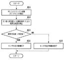
先ず、モータ/ジェネレータMG1を駆動して、内燃機関の始動前にクランクシャフトを回転駆動するモータリングを実施する(ステップS1)。これにより、エンジンのシリンダ内で圧縮された空気の圧縮熱により排気系の温度を上昇させる。尚、このとき、エンジン22の吸気系から導入される空気量と空気圧縮熱による排気管22Eの壁面温度との間には、例えば、図4に示すような関係にあり、排気管22Eの壁面温度を効率よく上昇させるための最適な空気量が存在する。このため、スロットルバルブを制御して最適な空気量となるように制御する。
First, the motor / generator MG1 is driven to perform motoring for rotationally driving the crankshaft before starting the internal combustion engine (step S1). Thereby, the temperature of the exhaust system is raised by the compression heat of the air compressed in the cylinder of the engine. At this time, for example, the relationship between the amount of air introduced from the intake system of the
次いで、空燃比センサ100及び/又は酸素センサ200の周りの温度が排気ガスに含まれる水蒸気を凝結させない非凝結温度に達したか、すなわち、センサ周辺の温度が露点温度を越えているかを判断する(ステップS2)。露点温度を越えていない場合には処理を終了し、越えている場合には、空燃比センサ100及び/又は酸素センサ200に内蔵されたヒータへの通電を開始する(ステップS3)。
Next, it is determined whether the temperature around the air-
次いで、空燃比センサ100及び/又は酸素センサ200が活性化したかを判断する(ステップS4)。この判断は、例えば、センサの素子アドミタンス値が所定値を超えた場合には活性とする等の公知の手法を用いることができる。活性化していない場合には、処理を終了し、活性化していると判断される場合には、燃料をシリンダ内に供給するとともに点火してエンジンを始動させる(ステップS5)。
Next, it is determined whether the air-
次に、図5ないし図7を参照して、空燃比センサ100及び/又は酸素センサ200の周りの暖機が完了したかの判断方法の他の例について説明する。
Next, another example of a method for determining whether the warm-up around the air-
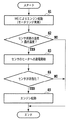
図5に示す方法では、上記と同様に、モータ/ジェネレータMG1を駆動して、内燃機関の始動前にクランクシャフトを回転駆動するモータリングを実施する(ステップS11)。このとき、モータリング中にシリンダ内に吸入された空気量に、実圧縮比に基く圧縮熱効率を掛け合わせて積算空気量を算出する(ステップS12)。この積算空気量は、排気管22Eの壁面温度上昇と相関を有するので、積算空気量が所定値を超えたかを判断し(ステップS13)、超えている場合には、センサ付近の暖機が完了(水蒸気を凝結させない非凝結温度に達している)と判断し(ステップS14)、超えていない場合には、センサ付近の暖機は未完了と判断する(ステップS15)。
In the method shown in FIG. 5, similarly to the above, the motor / generator MG1 is driven to perform motoring for rotationally driving the crankshaft before starting the internal combustion engine (step S11). At this time, the integrated air amount is calculated by multiplying the amount of air sucked into the cylinder during motoring by the compression heat efficiency based on the actual compression ratio (step S12). Since this integrated air amount has a correlation with the wall surface temperature rise of the
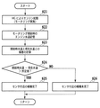
図6に示す方法では、上記と同様に、モータ/ジェネレータMG1を駆動して、内燃機関の始動前にクランクシャフトを回転駆動するモータリングを実施する(ステップS21)。このとき、モータリング開始時のエンジンの冷却水の水温を検出して記憶する(ステップS22)。そして、モータリング開始時のエンジンの冷却水の水温と現在の水温との偏差を計算する(ステップS23)。 In the method shown in FIG. 6, similarly to the above, the motor / generator MG1 is driven to perform motoring for rotationally driving the crankshaft before starting the internal combustion engine (step S21). At this time, the coolant temperature of the engine at the start of motoring is detected and stored (step S22). Then, the deviation between the coolant temperature of the engine at the start of motoring and the current water temperature is calculated (step S23).
計算した偏差、すなわち、水温上昇量は排気管22Eの壁面温度上昇と相関を有するので、この偏差が所定値を超えたかを判断する(ステップS24)。超えている場合には、センサ付近の暖機が完了(水蒸気を凝結させない非凝結温度に達している)と判断し(ステップS25)、超えていない場合には、センサ付近の暖機は未完了と判断する(ステップS26)。
Since the calculated deviation, that is, the amount of increase in the water temperature has a correlation with the increase in the wall surface temperature of the
図7に示す手法では、図6の場合の冷却水の水温に変えて、エンジンの潤滑油(エンジンオイル)の油温に基いて同様の判断をする(ステップS31〜S36)。エンジンフリクションによる摩擦熱からエンジンオイルの温度が上昇することを利用して、排気管22Eの壁面温度上昇を推定する。
In the method shown in FIG. 7, the same determination is made based on the oil temperature of the engine lubricating oil (engine oil) instead of the coolant temperature in the case of FIG. 6 (steps S31 to S36). The rise in the wall temperature of the
図8に示すフローチャートはさらに他の実施形態である。図8に示す処理ルーチンは所定時間毎にハイブリットECU70により実行される。
The flowchart shown in FIG. 8 is still another embodiment. The processing routine shown in FIG. 8 is executed by the
モータ/ジェネレータMG1を駆動して、内燃機関の始動前にクランクシャフトを回転駆動するモータリングを実施する(ステップS41)。このとき、大気圧を検出する(ステップS42)。大気圧が低いほど露点温度は低下するので、例えば、高地などを走行中には、露点温度は低下する。このため、例えば、図9に示すように、大気圧と排気管内の凝縮水の消滅時間との間には相関関係が存在する。したがって、現在の露点温度(メモリに記憶されている値)を検出した大気圧に基いて補正する(ステップS43)。 The motor / generator MG1 is driven to perform motoring for rotationally driving the crankshaft before starting the internal combustion engine (step S41). At this time, atmospheric pressure is detected (step S42). Since the dew point temperature decreases as the atmospheric pressure decreases, the dew point temperature decreases, for example, while traveling on high altitudes. Therefore, for example, as shown in FIG. 9, there is a correlation between the atmospheric pressure and the disappearance time of the condensed water in the exhaust pipe. Therefore, the current dew point temperature (value stored in the memory) is corrected based on the detected atmospheric pressure (step S43).
次いで、センサ周辺の温度が露点温度を越えているかを判断する(ステップS44)。露点温度が補正されて低下した場合には、センサ周辺の温度が露点温度に達するまでの時間は早まる。 Next, it is determined whether the temperature around the sensor exceeds the dew point temperature (step S44). When the dew point temperature is corrected and lowered, the time until the temperature around the sensor reaches the dew point temperature is accelerated.
次いで、上記と同様に、露点温度を越えていない場合には処理を終了し、越えている場合には、空燃比センサ100及び/又は酸素センサ200に内蔵されたヒータへの通電を開始し(ステップS45)、空燃比センサ100及び/又は酸素センサ200が活性化したかを判断し(ステップS46)、活性化していると判断される場合には、燃料をシリンダ内に供給するとともに点火してエンジンを始動させる(ステップS47)。
Next, similarly to the above, when the dew point temperature has not been exceeded, the processing is terminated, and when it has exceeded, energization of the heater built in the air-
このように、大気圧に基いて露点温度を補正することで、エンジンの起動タイミングを早めることができる。 As described above, the start timing of the engine can be advanced by correcting the dew point temperature based on the atmospheric pressure.
図10は本発明の他の実施形態を示しフローチャートであって、シリンダ内の実圧縮比を向上させる方法を示している。尚、図10の処理ルーチンは所定時間毎にハイブリットECU70により実行される。
FIG. 10 is a flowchart showing another embodiment of the present invention, and shows a method for improving the actual compression ratio in the cylinder. Note that the processing routine of FIG. 10 is executed by the
図10に示す方法では、ステップS52及びS53以外は、上記と同様の処理なので詳細説明を省略する。 Since the method shown in FIG. 10 is the same as that described above except for steps S52 and S53, detailed description thereof will be omitted.
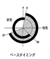
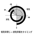
モータリングの際、ステップS52において、VVT150のバルブタイミングを最適化し、実圧縮比を上昇させる(ステップS53)。具体的には、図11に示すバルブタイミングを基準タイミングとすると、例えば、図12に示すように、吸気弁を閉じるタイミングを基準タイミングよりも早める。これにより、下死点で早閉じし吸入した空気をできるだけシリンダ内に留め、圧縮熱を高める。さらに、図13に示すように、排気弁の開放タイミングを基準タイミングよりも早める。これにより、温度上昇した空気を早開きすることで、素早く排気系に排出し、圧縮熱を効率良く排気系に流入させることができる。なお、本実施形態では、吸気弁及び排気弁の双方のタイミングを調整したが、いずれか一方のみでもよい。
During motoring, in step S52, the valve timing of the
図14は本発明のさらに他の実施形態を示しフローチャートであって、モータリングの際の圧縮熱効率を向上させる方法を示している。尚、図14の処理ルーチンは所定時間毎にハイブリットECU70により実行される。
FIG. 14 is a flowchart showing still another embodiment of the present invention, and shows a method for improving the compression thermal efficiency during motoring. Note that the processing routine of FIG. 14 is executed by the
図14に示す方法では、ステップS62及びS63以外は、上記と同様の処理なので詳細説明を省略する。 Since the method shown in FIG. 14 is the same as that described above except for steps S62 and S63, a detailed description thereof will be omitted.
ステップS62では、吸気弁を閉じるとともに、図13において説明したように、VVT150の排気バルブのタイミングを最適化する。吸気弁を閉じると、新気がシリンダに流入するのを抑制でき、圧縮熱を効率的に排気系に流入させる。これにより、圧縮熱効率が上昇する(ステップS63)。
In step S62, the intake valve is closed and the timing of the exhaust valve of the
図15は本発明のさらに他の実施形態を示しフローチャートであって、モータリングの際の圧縮空気量を向上させる方法を示している。尚、図15の処理ルーチンは所定時間毎にハイブリットECU70により実行される。
FIG. 15 is a flowchart showing still another embodiment of the present invention, and shows a method for improving the amount of compressed air during motoring. Note that the processing routine of FIG. 15 is executed by the
図15に示す方法では、ステップS73及びS74以外は、上記と同様の処理なので詳細説明を省略する。 Since the method shown in FIG. 15 is the same as that described above except for steps S73 and S74, detailed description thereof is omitted.
モータリングの際、ステップS73において、スロットルバルブの開度を開いて圧縮する空気量を増加(最適化)させる(図4も参照)。すなわち、圧縮熱効率の最も高い空気量に設定する。これにより、圧縮空気量が増加し(ステップS74)、圧縮空気熱を最大限に引き出すことができる。 During motoring, in step S73, the opening of the throttle valve is opened to increase (optimize) the amount of air to be compressed (see also FIG. 4). That is, the air amount with the highest compression heat efficiency is set. Thereby, the amount of compressed air increases (step S74), and compressed air heat can be extracted to the maximum.
上記実施形態では、ハイブリッド車両に適用した場合を例示したが、これに限定されるわけではなく、動力源として内燃機関のみを備える車両においても、モータリングが可能であれば本発明は適用可能である。 In the above embodiment, the case where the present invention is applied to a hybrid vehicle has been exemplified. However, the present invention is not limited to this, and the present invention can be applied to a vehicle including only an internal combustion engine as a power source as long as motoring is possible. is there.
20…車両
22…エンジン
24…エンジンECU
70…ハイブリッドECU
MG1,MG2…モータ/ジェネレータ
20 ...
70 ... Hybrid ECU
MG1, MG2 ... Motor / Generator
Claims (9)
内燃機関のシリンダ内で圧縮された空気の圧縮熱により前記排気系の温度を上昇させるために、内燃機関の始動前にクランクシャフトを回転駆動するモータリング手段と、
前記排気ガスセンサの周りの温度が排気ガスに含まれる水蒸気を凝結させない非凝結温度に達したかを判断する判断手段と、
前記排気ガスセンサの周りの温度が前記非凝結温度に達したと判断した後に、前記ヒータを起動させるヒータ起動手段と、
を有する内燃機関の制御装置。 An internal combustion engine control device comprising an exhaust gas sensor provided in an exhaust system and a heater for activating the exhaust gas sensor,
Motoring means for rotationally driving the crankshaft before starting the internal combustion engine in order to increase the temperature of the exhaust system by the compression heat of the air compressed in the cylinder of the internal combustion engine;
Determining means for determining whether the temperature around the exhaust gas sensor has reached a non-condensing temperature that does not condense water vapor contained in the exhaust gas;
Heater activation means for activating the heater after determining that the temperature around the exhaust gas sensor has reached the non-condensing temperature;
A control apparatus for an internal combustion engine.
前記モータリング手段による前記クランクシャフトの回転駆動中に吸気バルブを閉鎖させる制御手段をさらに有することを特徴とする請求項1ないし3のいずれかに記載の内燃機関の制御装置。 The internal combustion engine includes a variable valve timing mechanism in which the opening and closing timing of the intake valve and the exhaust valve of the internal combustion engine is variable,
4. The control apparatus for an internal combustion engine according to claim 1, further comprising control means for closing an intake valve during rotation driving of the crankshaft by the motoring means.
前記モータリング手段による前記クランクシャフトの回転駆動中に、シリンダ内の圧縮熱効率が高まるように吸気弁バルブ及び排気バルブの開閉タイミングを制御する制御手段をさらに有することを特徴とする請求項1ないし3のいずれかに記載の内燃機関の制御装置。 The internal combustion engine includes a variable valve timing mechanism in which the opening and closing timing of the intake valve and the exhaust valve of the internal combustion engine is variable,
4. A control unit for controlling opening / closing timings of an intake valve and an exhaust valve so that compression heat efficiency in a cylinder is increased during rotation driving of the crankshaft by the motoring unit. The control apparatus for an internal combustion engine according to any one of the above.
Priority Applications (1)
| Application Number | Priority Date | Filing Date | Title |
|---|---|---|---|
| JP2008153392A JP5302576B2 (en) | 2008-06-11 | 2008-06-11 | Control device for internal combustion engine |
Applications Claiming Priority (1)
| Application Number | Priority Date | Filing Date | Title |
|---|---|---|---|
| JP2008153392A JP5302576B2 (en) | 2008-06-11 | 2008-06-11 | Control device for internal combustion engine |
Publications (2)
| Publication Number | Publication Date |
|---|---|
| JP2009299538A true JP2009299538A (en) | 2009-12-24 |
| JP5302576B2 JP5302576B2 (en) | 2013-10-02 |
Family
ID=41546682
Family Applications (1)
| Application Number | Title | Priority Date | Filing Date |
|---|---|---|---|
| JP2008153392A Expired - Fee Related JP5302576B2 (en) | 2008-06-11 | 2008-06-11 | Control device for internal combustion engine |
Country Status (1)
| Country | Link |
|---|---|
| JP (1) | JP5302576B2 (en) |
Cited By (9)
| Publication number | Priority date | Publication date | Assignee | Title |
|---|---|---|---|---|
| JP2012172592A (en) * | 2011-02-22 | 2012-09-10 | Suzuki Motor Corp | Internal combustion engine control device |
| US20160319764A1 (en) * | 2012-12-07 | 2016-11-03 | Ethanol Boosting Systems, Llc | Gasoline Particulate Reduction Using Optimized Port And Direct Injection |
| US9976496B2 (en) | 2012-12-07 | 2018-05-22 | Ethanol Boosting Systems, Llc | Port injection system for reduction of particulates from turbocharged direct injection gasoline engines |
| DE102018101825A1 (en) | 2017-01-26 | 2018-07-26 | Toyota Jidosha Kabushiki Kaisha | Control system of an internal combustion engine |
| US10227945B2 (en) | 2016-09-26 | 2019-03-12 | Ethanol Boosting Systems, Llc | Gasoline particulate reduction using optimized port fuel injection plus direct injection |
| CN110678633A (en) * | 2017-05-17 | 2020-01-10 | 标致雪铁龙汽车股份有限公司 | Method for determining entry into a liquid water-free state in an exhaust line |
| US11280275B2 (en) | 2018-07-27 | 2022-03-22 | Aisin Corporation | Internal combustion engine |
| CN114901930A (en) * | 2020-01-30 | 2022-08-12 | 康明斯公司 | System and method for regulating an aftertreatment system using an electric motor driven internal combustion engine |
| CN119467113A (en) * | 2024-11-01 | 2025-02-18 | 东风商用车有限公司 | Oxygen sensor control method, controller, vehicle and storage medium |
Citations (5)
| Publication number | Priority date | Publication date | Assignee | Title |
|---|---|---|---|---|
| JPH0874645A (en) * | 1994-08-31 | 1996-03-19 | Mitsubishi Motors Corp | Hybrid engine start control device |
| JP2003049700A (en) * | 2001-08-02 | 2003-02-21 | Nissan Motor Co Ltd | Exhaust gas sensor heater control device |
| JP2007064089A (en) * | 2005-08-31 | 2007-03-15 | Toyota Motor Corp | Temperature estimation device for exhaust system parts of internal combustion engine |
| JP2007138832A (en) * | 2005-11-18 | 2007-06-07 | Denso Corp | Gas sensor heater control device |
| JP2007198202A (en) * | 2006-01-25 | 2007-08-09 | Toyota Motor Corp | Control device for internal combustion engine |
-
2008
- 2008-06-11 JP JP2008153392A patent/JP5302576B2/en not_active Expired - Fee Related
Patent Citations (5)
| Publication number | Priority date | Publication date | Assignee | Title |
|---|---|---|---|---|
| JPH0874645A (en) * | 1994-08-31 | 1996-03-19 | Mitsubishi Motors Corp | Hybrid engine start control device |
| JP2003049700A (en) * | 2001-08-02 | 2003-02-21 | Nissan Motor Co Ltd | Exhaust gas sensor heater control device |
| JP2007064089A (en) * | 2005-08-31 | 2007-03-15 | Toyota Motor Corp | Temperature estimation device for exhaust system parts of internal combustion engine |
| JP2007138832A (en) * | 2005-11-18 | 2007-06-07 | Denso Corp | Gas sensor heater control device |
| JP2007198202A (en) * | 2006-01-25 | 2007-08-09 | Toyota Motor Corp | Control device for internal combustion engine |
Cited By (22)
| Publication number | Priority date | Publication date | Assignee | Title |
|---|---|---|---|---|
| JP2012172592A (en) * | 2011-02-22 | 2012-09-10 | Suzuki Motor Corp | Internal combustion engine control device |
| US11371448B2 (en) | 2012-12-07 | 2022-06-28 | Ethanol Boosting Systems, Llc | Port injection system for reduction of particulates from turbocharged direct injection gasoline engines |
| US11125171B1 (en) | 2012-12-07 | 2021-09-21 | Ethanol Boosting Systems, Llc | Port injection system for reduction of particulates from turbocharged direct injection gasoline engines |
| US9976496B2 (en) | 2012-12-07 | 2018-05-22 | Ethanol Boosting Systems, Llc | Port injection system for reduction of particulates from turbocharged direct injection gasoline engines |
| US11959428B2 (en) | 2012-12-07 | 2024-04-16 | Ethanol Boosting Systems, Llc | Port injection system for reduction of particulates from turbocharged direct injection gasoline engines |
| US11624328B2 (en) | 2012-12-07 | 2023-04-11 | Ethanol Boosting Systems, Inc. | Port injection system for reduction of particulates from turbocharged direct injection gasoline engines |
| US20160319764A1 (en) * | 2012-12-07 | 2016-11-03 | Ethanol Boosting Systems, Llc | Gasoline Particulate Reduction Using Optimized Port And Direct Injection |
| US10288005B2 (en) | 2012-12-07 | 2019-05-14 | Ethanol Boosting Systems, Llc | Gasoline particulate reduction using optimized port and direct injection |
| US11371449B1 (en) | 2012-12-07 | 2022-06-28 | Ethanol Boosting Systems, Llc | Port injection system for reduction of particulates from turbocharged direct injection gasoline engines |
| US10683816B2 (en) | 2012-12-07 | 2020-06-16 | Ethanol Boosting Systems, Llc | Port injection system for reduction of particulates from turbocharged direct injection gasoline engines |
| US10774759B2 (en) | 2012-12-07 | 2020-09-15 | Ethanol Boosting Systems, Llc | Port injection system for reduction of particulates from turbocharged direct injection gasoline engines |
| US9840980B2 (en) * | 2012-12-07 | 2017-12-12 | Ethanol Boosting Systems, Llc | Gasoline particulate reduction using optimized port and direct injection |
| US11053869B2 (en) | 2012-12-07 | 2021-07-06 | Ethanol Boosting Systems, Llc | Port injection system for reduction of particulates from turbocharged direct injection gasoline engines |
| US10227945B2 (en) | 2016-09-26 | 2019-03-12 | Ethanol Boosting Systems, Llc | Gasoline particulate reduction using optimized port fuel injection plus direct injection |
| US10288001B2 (en) | 2017-01-26 | 2019-05-14 | Toyota Jidosha Kabushiki Kaisha | Control system of internal combustion engine |
| DE102018101825B4 (en) | 2017-01-26 | 2022-12-08 | Toyota Jidosha Kabushiki Kaisha | Internal combustion engine control system |
| DE102018101825A1 (en) | 2017-01-26 | 2018-07-26 | Toyota Jidosha Kabushiki Kaisha | Control system of an internal combustion engine |
| CN110678633A (en) * | 2017-05-17 | 2020-01-10 | 标致雪铁龙汽车股份有限公司 | Method for determining entry into a liquid water-free state in an exhaust line |
| US11280275B2 (en) | 2018-07-27 | 2022-03-22 | Aisin Corporation | Internal combustion engine |
| CN114901930A (en) * | 2020-01-30 | 2022-08-12 | 康明斯公司 | System and method for regulating an aftertreatment system using an electric motor driven internal combustion engine |
| CN119467113A (en) * | 2024-11-01 | 2025-02-18 | 东风商用车有限公司 | Oxygen sensor control method, controller, vehicle and storage medium |
| CN119467113B (en) * | 2024-11-01 | 2025-09-05 | 东风商用车有限公司 | Oxygen sensor control method, controller, vehicle and storage medium |
Also Published As
| Publication number | Publication date |
|---|---|
| JP5302576B2 (en) | 2013-10-02 |
Similar Documents
| Publication | Publication Date | Title |
|---|---|---|
| JP5302576B2 (en) | Control device for internal combustion engine | |
| US7059116B2 (en) | Power output apparatus and control method for same | |
| JP3941705B2 (en) | Internal combustion engine stop / start control device | |
| US20190263382A1 (en) | Mitigation of powertrain and accessory torsional oscillation through electric motor/generator control | |
| JP3959084B2 (en) | Manifold absolute pressure control system and method for hybrid electric vehicle | |
| CN101389515B (en) | Control apparatus and method for internal combustion engine | |
| EP1288491A2 (en) | Automatic stop and start control system for internal combustion engine | |
| JP5943090B2 (en) | Start control device for direct injection engine for vehicle | |
| US20230287839A1 (en) | Mitigation of powertrain and accessory torsional oscillation through electric motor/generator control | |
| RU2701632C2 (en) | Hybrid vehicle starting method (embodiments) | |
| JP4453641B2 (en) | Control device for internal combustion engine | |
| JP2005273530A (en) | Control device for internal combustion engine and automobile equipped with the same | |
| JP5904131B2 (en) | Hybrid vehicle control device and hybrid vehicle | |
| JP2006144725A (en) | Fuel injection control device for hybrid vehicle | |
| JP4737128B2 (en) | Engine start control device and start control method | |
| JP2006291792A (en) | Control device for internal combustion engine | |
| CN100580238C (en) | Control devices for internal combustion engines | |
| JP2013216223A (en) | Hybrid vehicle | |
| JP2005201197A (en) | Internal combustion engine control device, internal combustion engine control method, and automobile | |
| JP2009091961A (en) | INTERNAL COMBUSTION ENGINE DEVICE, ITS CONTROL METHOD, AND VEHICLE | |
| JP2013096232A (en) | Vehicle control device | |
| JP2013136335A (en) | Hybrid vehicle | |
| JP5724656B2 (en) | Control device for internal combustion engine | |
| KR20180050996A (en) | Method and appratus for controlling mhsg of mild hybrid electric vehicle | |
| JP6049989B2 (en) | Hybrid car |
Legal Events
| Date | Code | Title | Description |
|---|---|---|---|
| A621 | Written request for application examination |
Free format text: JAPANESE INTERMEDIATE CODE: A621 Effective date: 20101124 |
|
| A977 | Report on retrieval |
Free format text: JAPANESE INTERMEDIATE CODE: A971007 Effective date: 20111226 |
|
| A131 | Notification of reasons for refusal |
Free format text: JAPANESE INTERMEDIATE CODE: A131 Effective date: 20120106 |
|
| A521 | Written amendment |
Free format text: JAPANESE INTERMEDIATE CODE: A523 Effective date: 20120216 |
|
| A02 | Decision of refusal |
Free format text: JAPANESE INTERMEDIATE CODE: A02 Effective date: 20120511 |
|
| A521 | Written amendment |
Free format text: JAPANESE INTERMEDIATE CODE: A523 Effective date: 20120730 |
|
| A911 | Transfer of reconsideration by examiner before appeal (zenchi) |
Free format text: JAPANESE INTERMEDIATE CODE: A911 Effective date: 20120807 |
|
| A912 | Removal of reconsideration by examiner before appeal (zenchi) |
Free format text: JAPANESE INTERMEDIATE CODE: A912 Effective date: 20120831 |
|
| A61 | First payment of annual fees (during grant procedure) |
Free format text: JAPANESE INTERMEDIATE CODE: A61 Effective date: 20130621 |
|
| R151 | Written notification of patent or utility model registration |
Ref document number: 5302576 Country of ref document: JP Free format text: JAPANESE INTERMEDIATE CODE: R151 |
|
| LAPS | Cancellation because of no payment of annual fees |