JP2009303473A - モータおよびそれを用いた送風ファン - Google Patents
モータおよびそれを用いた送風ファン Download PDFInfo
- Publication number
- JP2009303473A JP2009303473A JP2009030984A JP2009030984A JP2009303473A JP 2009303473 A JP2009303473 A JP 2009303473A JP 2009030984 A JP2009030984 A JP 2009030984A JP 2009030984 A JP2009030984 A JP 2009030984A JP 2009303473 A JP2009303473 A JP 2009303473A
- Authority
- JP
- Japan
- Prior art keywords
- magnetic member
- central axis
- motor
- armature
- field magnet
- Prior art date
- Legal status (The legal status is an assumption and is not a legal conclusion. Google has not performed a legal analysis and makes no representation as to the accuracy of the status listed.)
- Granted
Links
- 239000012212 insulator Substances 0.000 claims abstract description 106
- 230000007246 mechanism Effects 0.000 claims description 5
- 238000010586 diagram Methods 0.000 description 7
- 238000000034 method Methods 0.000 description 6
- 210000000078 claw Anatomy 0.000 description 5
- 238000003780 insertion Methods 0.000 description 4
- 230000037431 insertion Effects 0.000 description 4
- 238000005304 joining Methods 0.000 description 3
- 239000010687 lubricating oil Substances 0.000 description 3
- 238000005520 cutting process Methods 0.000 description 2
- 229910052751 metal Inorganic materials 0.000 description 2
- 239000002184 metal Substances 0.000 description 2
- 238000003825 pressing Methods 0.000 description 2
- 239000000758 substrate Substances 0.000 description 2
- 229910000976 Electrical steel Inorganic materials 0.000 description 1
- 229910001335 Galvanized steel Inorganic materials 0.000 description 1
- 229910052782 aluminium Inorganic materials 0.000 description 1
- XAGFODPZIPBFFR-UHFFFAOYSA-N aluminium Chemical compound [Al] XAGFODPZIPBFFR-UHFFFAOYSA-N 0.000 description 1
- 238000005452 bending Methods 0.000 description 1
- 230000008901 benefit Effects 0.000 description 1
- 230000008859 change Effects 0.000 description 1
- 238000004512 die casting Methods 0.000 description 1
- 230000005489 elastic deformation Effects 0.000 description 1
- 239000008397 galvanized steel Substances 0.000 description 1
- 230000014509 gene expression Effects 0.000 description 1
- 230000005484 gravity Effects 0.000 description 1
- 238000001746 injection moulding Methods 0.000 description 1
- 239000011810 insulating material Substances 0.000 description 1
- 238000009413 insulation Methods 0.000 description 1
- 238000010030 laminating Methods 0.000 description 1
- WABPQHHGFIMREM-UHFFFAOYSA-N lead(0) Chemical compound [Pb] WABPQHHGFIMREM-UHFFFAOYSA-N 0.000 description 1
- 239000000696 magnetic material Substances 0.000 description 1
- 230000005389 magnetism Effects 0.000 description 1
- 230000002093 peripheral effect Effects 0.000 description 1
- 230000008569 process Effects 0.000 description 1
- 230000009467 reduction Effects 0.000 description 1
- 239000011347 resin Substances 0.000 description 1
- 229920005989 resin Polymers 0.000 description 1
- 238000004804 winding Methods 0.000 description 1
Images














Classifications
-
- F—MECHANICAL ENGINEERING; LIGHTING; HEATING; WEAPONS; BLASTING
- F04—POSITIVE - DISPLACEMENT MACHINES FOR LIQUIDS; PUMPS FOR LIQUIDS OR ELASTIC FLUIDS
- F04D—NON-POSITIVE-DISPLACEMENT PUMPS
- F04D25/00—Pumping installations or systems
- F04D25/02—Units comprising pumps and their driving means
- F04D25/06—Units comprising pumps and their driving means the pump being electrically driven
- F04D25/0606—Units comprising pumps and their driving means the pump being electrically driven the electric motor being specially adapted for integration in the pump
- F04D25/0613—Units comprising pumps and their driving means the pump being electrically driven the electric motor being specially adapted for integration in the pump the electric motor being of the inside-out type, i.e. the rotor is arranged radially outside a central stator
- F04D25/0633—Details of the magnetic circuit
-
- F—MECHANICAL ENGINEERING; LIGHTING; HEATING; WEAPONS; BLASTING
- F04—POSITIVE - DISPLACEMENT MACHINES FOR LIQUIDS; PUMPS FOR LIQUIDS OR ELASTIC FLUIDS
- F04D—NON-POSITIVE-DISPLACEMENT PUMPS
- F04D25/00—Pumping installations or systems
- F04D25/02—Units comprising pumps and their driving means
- F04D25/06—Units comprising pumps and their driving means the pump being electrically driven
- F04D25/0606—Units comprising pumps and their driving means the pump being electrically driven the electric motor being specially adapted for integration in the pump
- F04D25/0613—Units comprising pumps and their driving means the pump being electrically driven the electric motor being specially adapted for integration in the pump the electric motor being of the inside-out type, i.e. the rotor is arranged radially outside a central stator
- F04D25/0646—Details of the stator
-
- F—MECHANICAL ENGINEERING; LIGHTING; HEATING; WEAPONS; BLASTING
- F04—POSITIVE - DISPLACEMENT MACHINES FOR LIQUIDS; PUMPS FOR LIQUIDS OR ELASTIC FLUIDS
- F04D—NON-POSITIVE-DISPLACEMENT PUMPS
- F04D29/00—Details, component parts, or accessories
- F04D29/60—Mounting; Assembling; Disassembling
- F04D29/64—Mounting; Assembling; Disassembling of axial pumps
- F04D29/644—Mounting; Assembling; Disassembling of axial pumps especially adapted for elastic fluid pumps
- F04D29/646—Mounting or removal of fans
-
- H—ELECTRICITY
- H02—GENERATION; CONVERSION OR DISTRIBUTION OF ELECTRIC POWER
- H02K—DYNAMO-ELECTRIC MACHINES
- H02K1/00—Details of the magnetic circuit
- H02K1/06—Details of the magnetic circuit characterised by the shape, form or construction
- H02K1/12—Stationary parts of the magnetic circuit
- H02K1/18—Means for mounting or fastening magnetic stationary parts on to, or to, the stator structures
- H02K1/187—Means for mounting or fastening magnetic stationary parts on to, or to, the stator structures to inner stators
-
- H—ELECTRICITY
- H02—GENERATION; CONVERSION OR DISTRIBUTION OF ELECTRIC POWER
- H02K—DYNAMO-ELECTRIC MACHINES
- H02K5/00—Casings; Enclosures; Supports
- H02K5/04—Casings or enclosures characterised by the shape, form or construction thereof
- H02K5/16—Means for supporting bearings, e.g. insulating supports or means for fitting bearings in the bearing-shields
- H02K5/163—Means for supporting bearings, e.g. insulating supports or means for fitting bearings in the bearing-shields radially supporting the rotary shaft at only one end of the rotor
-
- F—MECHANICAL ENGINEERING; LIGHTING; HEATING; WEAPONS; BLASTING
- F05—INDEXING SCHEMES RELATING TO ENGINES OR PUMPS IN VARIOUS SUBCLASSES OF CLASSES F01-F04
- F05D—INDEXING SCHEME FOR ASPECTS RELATING TO NON-POSITIVE-DISPLACEMENT MACHINES OR ENGINES, GAS-TURBINES OR JET-PROPULSION PLANTS
- F05D2260/00—Function
- F05D2260/30—Retaining components in desired mutual position
- F05D2260/36—Retaining components in desired mutual position by a form fit connection, e.g. by interlocking
-
- H—ELECTRICITY
- H02—GENERATION; CONVERSION OR DISTRIBUTION OF ELECTRIC POWER
- H02K—DYNAMO-ELECTRIC MACHINES
- H02K1/00—Details of the magnetic circuit
- H02K1/06—Details of the magnetic circuit characterised by the shape, form or construction
- H02K1/12—Stationary parts of the magnetic circuit
- H02K1/14—Stator cores with salient poles
- H02K1/146—Stator cores with salient poles consisting of a generally annular yoke with salient poles
-
- H—ELECTRICITY
- H02—GENERATION; CONVERSION OR DISTRIBUTION OF ELECTRIC POWER
- H02K—DYNAMO-ELECTRIC MACHINES
- H02K2211/00—Specific aspects not provided for in the other groups of this subclass relating to measuring or protective devices or electric components
- H02K2211/03—Machines characterised by circuit boards, e.g. pcb
-
- H—ELECTRICITY
- H02—GENERATION; CONVERSION OR DISTRIBUTION OF ELECTRIC POWER
- H02K—DYNAMO-ELECTRIC MACHINES
- H02K7/00—Arrangements for handling mechanical energy structurally associated with dynamo-electric machines, e.g. structural association with mechanical driving motors or auxiliary dynamo-electric machines
- H02K7/08—Structural association with bearings
- H02K7/09—Structural association with bearings with magnetic bearings
-
- H—ELECTRICITY
- H02—GENERATION; CONVERSION OR DISTRIBUTION OF ELECTRIC POWER
- H02K—DYNAMO-ELECTRIC MACHINES
- H02K7/00—Arrangements for handling mechanical energy structurally associated with dynamo-electric machines, e.g. structural association with mechanical driving motors or auxiliary dynamo-electric machines
- H02K7/14—Structural association with mechanical loads, e.g. with hand-held machine tools or fans
Landscapes
- Engineering & Computer Science (AREA)
- Mechanical Engineering (AREA)
- General Engineering & Computer Science (AREA)
- Power Engineering (AREA)
- Brushless Motors (AREA)
- Connection Of Motors, Electrical Generators, Mechanical Devices, And The Like (AREA)
- Motor Or Generator Frames (AREA)
- Structures Of Non-Positive Displacement Pumps (AREA)
Abstract
【解決手段】ロータ部121が、有蓋略円筒状のロータホルダ1211と、ロータホルダ1211の内側に取り付けられた界磁用磁石1213とを備える。ステータ部122が、電機子1222と、電機子1222が固定されるベース部1221と、磁性部材1224とを備える。磁性部材1224が、電機子のインシュレータの中心軸を中心とする径方向外側におけるベース部側の端部が貫通する略円筒状の円筒部51と、円筒部のベース部側の端部から中心軸を中心とする径方向外方へと広がり、界磁用磁石1213のベース部側の端部に対向する略環状の平板部52とを備えている。
【選択図】図1
Description
また、米国特許第6097120号明細書に開示されるモータの他の構造では、バランシングシートとステータのコアとが、1つの部材として形成される。
しかし、上述の特許第4005670号公報および米国特許第6097120号明細書に示されるモータの構造では、磁性部材を界磁用磁石に十分に近づけるには、構造が複雑になったり、電機子の設計の自由度が低下してしまう。米国特許第7221069号明細書に示される磁性部材では、界磁用磁石が中心軸に垂直な方向のみに対向することから、十分な磁気的吸引力を確保することが困難である。
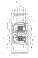
図1は、本発明の第1の実施形態に係り、送風ファンである軸流ファン1の縦断面図である。軸流ファン1は、電動式の単相モータ12(以下、「モータ12」という)、複数の翼11、モータ12の外周を囲むハウジング13、および、複数の支持リブ14を備える。ハウジング13は、支持リブ14によりモータ12に接続される。複数の翼11は、モータ12のロータ部121に固定されており、複数の支持リブ14は、モータ12を支持する。
ハウジング13および支持リブ14は、樹脂の射出成形により1つの部材として形成される。ハウジング13と支持リブ14は、アルミダイカストにて1つの部材として形成されてもよい。図1では、図示の都合上、翼11および支持リブ14の概略形状を中心軸J1の左右に示す。
金属製のヨーク1212は、中心軸J1を中心とする円筒状をしている。略円筒状の界磁用磁石1213は、ヨーク1212を介してロータホルダ1211の内側に取り付けられる。シャフト1214は、ロータホルダ1211の蓋部1211aの中央から下方に突出する。ロータホルダ1211の外周からは、複数の翼11が径方向外方へと突出する。
スリーブ1231には、ロータ部121のシャフト1214が挿入されて、シャフト1214の下端が、スラストプレート1233に当接する。スリーブ1231には潤滑油が含浸されており、スリーブハウジング1232により、スリーブ部123内に潤滑油が保持される。
しかし、以上のような構成とすることにより、モータ12を安定して回転させることができるとともに、過度の接触が回避されて、騒音や損傷を防止できる。
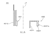
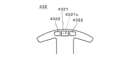
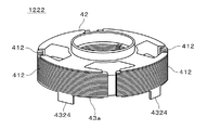
図2に示すように、ステータコア41は、略円筒状の中央部411、および、中央部411の外周から中心軸J1を中心として径方向外方に伸びるとともに、外側の端部において周方向の両側に広がるT字状の4つのティース部412を備える。下部インシュレータ43は、ステータコア41の中央部411に中心軸J1に平行な方向において重なる環状部431、および、ティース部412を覆う4つのティース被覆部432を備える。ティース部412は、ティース被覆部432よりも径方向外方に僅かに突出する。
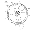
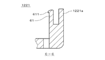
図8および図9に示すように、ベース部1221は、外周の側壁1221aの内側にて周方向に等間隔に、中心軸J1に平行に伸びる4つの突起61を有する。図9に示すように、突起61の先端611は、径方向内方に向かって僅かに突出する。図8および図10に示すように、突起61の周方向における両側には、2つの補助突起62が設けられる。
予め、ステータコア41に上部インシュレータ42(図1参照)および図2に示す下部インシュレータ43が取り付けられ、両インシュレータ上からステータコア41に導電線が巻回されることにより、電機子1222(図1参照)が準備される。
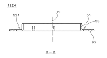
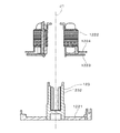
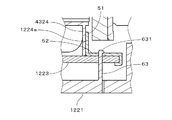
まず、図4に示す磁性部材1224が、穴部53を下部インシュレータ43の突出部4321に、中心軸J1に平行な方向に一致させつつ、下部インシュレータ43の下側に配置される。そして、下部インシュレータ43の突出部4321が、磁性部材1224の円筒部51の内側に挿入される。
磁性部材1224を下部インシュレータ43に取付ける作業は、ステータコア41に導電線を巻回してコイル形成した後に行われる。このため、作業工程が煩雑となることはない。
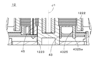
回路基板1223の穴部1223aに、電機子1222のピン45(図1参照)が挿入される。回路基板1223とピン45とが接合されることにより、回路基板1223と下部インシュレータ43とが固定される。回路基板1223を下部インシュレータ43に取付けでは、磁性部材1224の切欠部521を目印として、中心軸J1に垂直な方向における、回路基板1223の取付け方向、すなわち周方向の向きが容易に決定される。
以上の作業により、下部インシュレータ43およびベース部1221への、磁性部材1224の固定が完了する。図13に示す電機子1222とスリーブハウジング1232とは、圧入および接着により固定される。
簡単な構造の突出部4321により、磁性部材1224が安定して下部インシュレータ43に取り付けられる。円筒部51が突出部4321に外接することにより、磁性部材1224の中心軸をモータ12の中心軸J1に正確に一致させつつ、平板部52を容易に水平に、すなわち中心軸J1に対して垂直に、保つことができる。
これにより、磁性部材1224に切欠部が設けられる場合であっても、軸流ファン1では、界磁用磁石1213と磁性部材1224との間の磁気的吸引力の低下を、小さく抑えることができる。図4に示す切欠部521の周方向の幅が、ホール素子8の周方向の幅より大きく設定されるのであれば、切欠部521は径方向に細長いスリット状であってもよい。
回路基板1223では、切欠部521aを介してホール素子8が、界磁用磁石1213(図1参照)に中心軸J1に平行な方向に重なって配置される。図15に示す磁性部材1224の他の構造は、図4に示すものと同様である。図15の磁性部材1224においても、平板部52に設けられる切欠部521aの数が(実質的に)1つとしてよい。このことにより、界磁用磁石1213と磁性部材1224との間の磁気的吸引力の低下を、小さく抑えることができる。
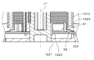
図17に示すように、折曲部525の先端は回路基板1223の上面に当接する。折曲部525の先端および回路基板1223の外縁部が、ベース部1221の突起61の先端611と補助突起62との間に固定される。
そして、円筒部51に完全に下部インシュレータ43が挿入されると、凸部511の先端が突出部4321の先端4321aよりも中心軸J1側へと移動して、磁性部材1224の中心軸J1方向の位置が固定される。これにより、円筒部51に下部インシュレータ43を、容易に挿入することが実現される。
図19は、第2の実施形態に係る軸流ファンの電機子1222、磁性部材1224aおよび回路基板1223を示す斜視図である。図20は、電機子1222の斜視図である。なお、図19および図20では、電機子1222の上部インシュレータ42の形状を簡略化している。
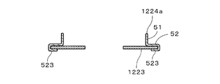
図19に示すように、磁性部材1224aには、平板部52の外周において周方向の4箇所に、一対の爪部523が等間隔に設けられる。磁性部材1224aでは、図4に示す穴部53が省略される。平板部52には1つの切欠部521が形成され、切欠部521が設けられる位置では、円筒部51は下端の一部のみが切り欠かれている。磁性部材1224aの他の構造は、磁性部材1224と同様であり、同様の構成には同符号を付す。
図19では折り曲げられる前の爪部523を示す。回路基板1223上には、絶縁フィルム等の絶縁材料が設けられており、磁性部材1224aと回路基板1223との絶縁性が確保される。回路基板1223上には、平板部52の切欠部521に対応する位置に、ホール素子8が取り付けられている。ホール素子8は切欠部521を介して、ロータ部121の界磁用磁石1213(図1参照)に対向する。
第2の実施形態に係る軸流ファンでは、ベース部1221の突起61が省略されており、磁性部材1224aは回路基板1223のみに固定される。磁性部材1224a、下部インシュレータ43aおよびベース部1221を除く、軸流ファンの他の構造は、第1の実施形態に係る軸流ファン1と同様である。
磁性部材1224aが、回路基板1223および電機子1222に固定される際には、まず、図21に示す回路基板1223が、磁性部材1224aの平板部52の内側に配置される。平板部52の下面が、回路基板1223の上面に当接するとともに、爪部523が、回路基板1223よりも下方に突出する。磁性部材1224aの爪部523が、回路基板1223の下面に当接するように内側に折り曲げられて、磁性部材1224aが回路基板1223に固定される。
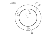
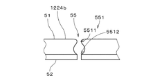
図23は、第3の実施形態に係る軸流ファンの磁性部材1224bを示す平面図である。磁性部材1224bでは、図4に示す磁性部材1224の穴部53が省略される。円筒部51では、図23における上側の一部が切り欠かれて、平板部52の一部が径方向内方に突出する。以下、平板部52のこの部位を「突起54」という。突起54と周方向において反対側、すなわち図23の下側には、磁性部材1224bを径方向に横断するスリット状の切欠部55が設けられる。他の形状は、磁性部材1224とほぼ同様である。
平板部52における切欠部55の周方向の幅は、軸方向切欠部551の下部5512の周方向における幅と、同じに設定される。
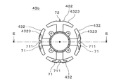
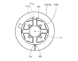
図30に示すように、下部インシュレータ43bに対して磁性部材1224bを傾けた状態にて、磁性部材1224bの突起54の先端が、突出部71aの溝部712に向かって下部インシュレータ43bの径方向外側から挿入される。このとき、図23に示す磁性部材1224bの切欠部55は、図24に示す下部インシュレータ43bの微小突起72の下方(図24における紙面手前側)に位置する。
8 ホール素子
11 翼
12 モータ
43,43a,43b 下部インシュレータ
51 (磁性部材の)円筒部
52 (磁性部材の)平板部
61 (ベース部の)突起
71,4321,4324 突出部
120 軸受機構
121 ロータ部
122 ステータ部
412 ティース部
432 ティース被覆部
521,521a (平板部の)切欠部
522 (平板部の)外縁部
1211 ロータホルダ
1213 界磁用磁石
1221 ベース部
1222 電機子
1223 回路基板
1224,1224a,1224b 磁性部材
4321a (突出部の)先端
4323 (ティース被覆部の)外縁部
J1 中心軸
Claims (9)
- ステータ部と、
中心軸を中心として回転するロータ部と、
前記ロータ部を前記ステータ部に対して回転可能に支持する軸受機構と、
を備え、
前記ロータ部が、
有蓋略円筒状のロータホルダと、
前記ロータホルダの内側に取り付けられた界磁用磁石と、
を備え、
前記ステータ部が、
前記ロータホルダの内側に配置され、前記界磁用磁石との間でトルクを発生する電機子と、
前記電機子の前記ロータホルダの蓋部とは前記中心軸方向において反対側に位置し、前記電機子が直接または間接的に固定されるベース部と、
前記界磁用磁石と前記ベース部との間に位置し、前記界磁用磁石との間に磁気的吸引力を発生する磁性部材と、
を備え、
前記磁性部材が、
前記電機子のインシュレータの前記中心軸を中心とする径方向外側における前記ベース部側の端部が貫通する略円筒状の円筒部と、
前記円筒部の前記ベース部側の端部から前記中心軸を中心とする径方向外方へと広がり、前記界磁用磁石の前記ベース部側の端部に対向する略環状の平板部と、
を備えるモータ。 - 請求項1に記載のモータにおいて、
前記円筒部が前記インシュレータの前記端部に外接するモータ。 - 請求項1または2に記載のモータにおいて、
前記電機子が、前記径方向外方に伸びる複数のティースを有し、
前記インシュレータの前記ベース部側の前記端部が前記複数のティースの先端側から前記ベース部に向かって突出する複数の突出部であるモータ。 - 請求項1ないし3のいずれかに記載のモータにおいて、
前記インシュレータが、前記磁性部材の前記円筒部に係合して前記磁性部材の前記中心軸方向における位置を固定する係合部を備えるモータ。 - 請求項4に記載のモータにおいて、
前記平板部が前記中心軸に平行な方向において前記ベース部に固定されるモータ。 - 請求項1ないし5のいずれかに記載のモータにおいて、
前記磁性部材と前記ベース部との間に、前記電機子に対して位置が固定された回路基板をさらに備え、
前記磁性部材の前記平板部が前記回路基板に固定されるモータ。 - 請求項1ないし6のいずれかに記載のモータにおいて、
前記平板部が切欠部を有し、
前記切欠部を介して前記界磁用磁石の回転位置を検出するホール素子と前記界磁用磁石とが対向するモータ。 - 請求項7に記載のモータにおいて、
前記平板部における前記切欠部の数が1つであるモータ。 - 請求項1ないし8のいずれかに記載のモータと、
前記モータの前記ロータホルダから前記径方向外方へと突出し、前記中心軸を中心として回転することによりエアの流れを発生する複数の翼と、
を備える送風ファン。
Priority Applications (2)
| Application Number | Priority Date | Filing Date | Title |
|---|---|---|---|
| JP2009030984A JP5360473B2 (ja) | 2008-05-16 | 2009-02-13 | モータおよびそれを用いた送風ファン |
| US12/466,404 US8092195B2 (en) | 2008-05-16 | 2009-05-15 | Motor and fan apparatus having the motor |
Applications Claiming Priority (3)
| Application Number | Priority Date | Filing Date | Title |
|---|---|---|---|
| JP2008129156 | 2008-05-16 | ||
| JP2008129156 | 2008-05-16 | ||
| JP2009030984A JP5360473B2 (ja) | 2008-05-16 | 2009-02-13 | モータおよびそれを用いた送風ファン |
Publications (2)
| Publication Number | Publication Date |
|---|---|
| JP2009303473A true JP2009303473A (ja) | 2009-12-24 |
| JP5360473B2 JP5360473B2 (ja) | 2013-12-04 |
Family
ID=41316345
Family Applications (1)
| Application Number | Title | Priority Date | Filing Date |
|---|---|---|---|
| JP2009030984A Expired - Fee Related JP5360473B2 (ja) | 2008-05-16 | 2009-02-13 | モータおよびそれを用いた送風ファン |
Country Status (2)
| Country | Link |
|---|---|
| US (1) | US8092195B2 (ja) |
| JP (1) | JP5360473B2 (ja) |
Cited By (8)
| Publication number | Priority date | Publication date | Assignee | Title |
|---|---|---|---|---|
| KR101113393B1 (ko) * | 2010-11-22 | 2012-02-29 | 삼성전기주식회사 | 모터용 베이스 어셈블리 및 이를 포함하는 모터 |
| JP2012077703A (ja) * | 2010-10-04 | 2012-04-19 | Nippon Densan Corp | ファン |
| JP2013032769A (ja) * | 2011-06-30 | 2013-02-14 | Nippon Densan Corp | ファン |
| JP2013061063A (ja) * | 2011-06-30 | 2013-04-04 | Nippon Densan Corp | 動圧軸受装置およびファン |
| JP2013165620A (ja) * | 2012-02-13 | 2013-08-22 | Minebea Co Ltd | ブラシレスモータおよび送風機 |
| JP2019161832A (ja) * | 2018-03-13 | 2019-09-19 | 日本電産株式会社 | モータおよびファンモータ |
| JPWO2021199236A1 (ja) * | 2020-03-31 | 2021-10-07 | ||
| JP2021170913A (ja) * | 2020-04-17 | 2021-10-28 | シナノケンシ株式会社 | アウターロータ型モータ |
Families Citing this family (19)
| Publication number | Priority date | Publication date | Assignee | Title |
|---|---|---|---|---|
| JP2010239858A (ja) * | 2009-03-12 | 2010-10-21 | Nippon Densan Corp | モータ |
| US8692430B2 (en) | 2011-02-01 | 2014-04-08 | Sunonwealth Electric Machine Industry Co., Ltd. | Motor and motor assembling method |
| US20120194009A1 (en) * | 2011-02-01 | 2012-08-02 | Alex Horng | Motor and Motor Assembling Method |
| KR20130030871A (ko) * | 2011-09-20 | 2013-03-28 | 삼성전기주식회사 | 모터용 베이스 어셈블리 및 이를 포함하는 모터 |
| KR101228716B1 (ko) * | 2011-09-22 | 2013-02-01 | 삼성전기주식회사 | 모터용 베이스 어셈블리 및 이를 포함하는 모터 |
| US9388824B2 (en) * | 2011-11-18 | 2016-07-12 | Asia Vital Components Co., Ltd. | Salt-spray protection structure for fan |
| JP2013187922A (ja) | 2012-03-06 | 2013-09-19 | Nippon Densan Corp | ファンモータ |
| US9057380B2 (en) * | 2012-06-29 | 2015-06-16 | Asia Vital Components Co., Ltd. | Fan having debris entry prevention gap |
| CN105257562A (zh) * | 2015-10-13 | 2016-01-20 | 深圳市锦固鸿五金科技有限公司 | 一种用于笔记本电脑散热器的风扇 |
| CN107040069B (zh) * | 2016-02-03 | 2020-10-16 | 德昌电机(深圳)有限公司 | 电机及其定子 |
| CN107040056A (zh) | 2016-02-03 | 2017-08-11 | 德昌电机(深圳)有限公司 | 电机及其定子 |
| CN107040057A (zh) | 2016-02-03 | 2017-08-11 | 德昌电机(深圳)有限公司 | 风机 |
| CN107124064A (zh) * | 2016-02-25 | 2017-09-01 | 德昌电机(深圳)有限公司 | 风机及其外转子电机 |
| JP2018178802A (ja) * | 2017-04-07 | 2018-11-15 | 日本電産株式会社 | ファンモータ |
| KR102030783B1 (ko) * | 2017-12-06 | 2019-10-10 | 주식회사 아모텍 | 냉각 팬 |
| JP7611640B2 (ja) * | 2018-11-20 | 2025-01-10 | ニデック株式会社 | ステータ、モータ、および、送風装置 |
| DE102022207901A1 (de) * | 2022-08-01 | 2024-02-01 | Zf Friedrichshafen Ag | Stator für einen Elektromotor sowie Elektromotor, umfassend einen solchen Stator |
| TWI852880B (zh) * | 2024-01-30 | 2024-08-11 | 大陸商深圳興奇宏科技有限公司 | 風扇屏蔽結構 |
| FR3166408A1 (fr) * | 2024-09-15 | 2026-03-20 | Valeo Systemes Thermiques | Groupe moto-ventilateur notamment pour véhicule automobile |
Citations (5)
| Publication number | Priority date | Publication date | Assignee | Title |
|---|---|---|---|---|
| JP3255133B2 (ja) * | 1999-01-07 | 2002-02-12 | 松下電器産業株式会社 | Dcブラシレスファン |
| JP2002354742A (ja) * | 2001-05-22 | 2002-12-06 | Matsushita Electric Ind Co Ltd | スピンドルモータ |
| JP2003047222A (ja) * | 2001-07-30 | 2003-02-14 | Nippon Densan Corp | モータ |
| JP2003259596A (ja) * | 2002-03-06 | 2003-09-12 | Sankyo Seiki Mfg Co Ltd | スピンドルモータ |
| JP2007209091A (ja) * | 2006-01-31 | 2007-08-16 | Nippon Densan Corp | 送風ファン |
Family Cites Families (9)
| Publication number | Priority date | Publication date | Assignee | Title |
|---|---|---|---|---|
| JP4005670B2 (ja) | 1997-07-10 | 2007-11-07 | 日本電産コパル株式会社 | 軸流ファンモータ |
| US6097120A (en) * | 1999-09-04 | 2000-08-01 | Sunonwealth Electric Machine Industry Co., Ltd. | Brushless D.C. motor assembly |
| TWM243848U (en) * | 2003-07-09 | 2004-09-11 | Sunonwealth Electr Mach Ind Co | Rotational balance structure for a motor |
| JP4826718B2 (ja) * | 2004-07-27 | 2011-11-30 | 日本電産株式会社 | モータ用の電機子およびモータ |
| TWI306323B (en) * | 2005-02-14 | 2009-02-11 | Sunonwealth Electr Mach Ind Co | Motor structure |
| TWI329403B (en) * | 2005-04-19 | 2010-08-21 | Sunonwealth Electr Mach Ind Co | Rotor balance structure for motor |
| US7221069B2 (en) * | 2005-06-07 | 2007-05-22 | Sunonwealth Electric Machine Industry Co., Ltd. | Balancing structure for motor rotor |
| JP2007151349A (ja) * | 2005-11-29 | 2007-06-14 | Nippon Densan Corp | モータ |
| JP4992287B2 (ja) * | 2006-04-28 | 2012-08-08 | 日本電産株式会社 | モータ |
-
2009
- 2009-02-13 JP JP2009030984A patent/JP5360473B2/ja not_active Expired - Fee Related
- 2009-05-15 US US12/466,404 patent/US8092195B2/en not_active Expired - Fee Related
Patent Citations (5)
| Publication number | Priority date | Publication date | Assignee | Title |
|---|---|---|---|---|
| JP3255133B2 (ja) * | 1999-01-07 | 2002-02-12 | 松下電器産業株式会社 | Dcブラシレスファン |
| JP2002354742A (ja) * | 2001-05-22 | 2002-12-06 | Matsushita Electric Ind Co Ltd | スピンドルモータ |
| JP2003047222A (ja) * | 2001-07-30 | 2003-02-14 | Nippon Densan Corp | モータ |
| JP2003259596A (ja) * | 2002-03-06 | 2003-09-12 | Sankyo Seiki Mfg Co Ltd | スピンドルモータ |
| JP2007209091A (ja) * | 2006-01-31 | 2007-08-16 | Nippon Densan Corp | 送風ファン |
Cited By (14)
| Publication number | Priority date | Publication date | Assignee | Title |
|---|---|---|---|---|
| JP2012077703A (ja) * | 2010-10-04 | 2012-04-19 | Nippon Densan Corp | ファン |
| KR101113393B1 (ko) * | 2010-11-22 | 2012-02-29 | 삼성전기주식회사 | 모터용 베이스 어셈블리 및 이를 포함하는 모터 |
| JP2013032769A (ja) * | 2011-06-30 | 2013-02-14 | Nippon Densan Corp | ファン |
| JP2013061063A (ja) * | 2011-06-30 | 2013-04-04 | Nippon Densan Corp | 動圧軸受装置およびファン |
| US9341189B2 (en) | 2011-06-30 | 2016-05-17 | Nidec Corporation | Fan |
| JP2013165620A (ja) * | 2012-02-13 | 2013-08-22 | Minebea Co Ltd | ブラシレスモータおよび送風機 |
| JP2019161832A (ja) * | 2018-03-13 | 2019-09-19 | 日本電産株式会社 | モータおよびファンモータ |
| JP7210886B2 (ja) | 2018-03-13 | 2023-01-24 | 日本電産株式会社 | モータおよびファンモータ |
| JPWO2021199236A1 (ja) * | 2020-03-31 | 2021-10-07 | ||
| WO2021199236A1 (ja) * | 2020-03-31 | 2021-10-07 | 平田機工株式会社 | 回転電機 |
| US12355326B2 (en) | 2020-03-31 | 2025-07-08 | Hirata Corporation | Dynamo-electric machine |
| JP2021170913A (ja) * | 2020-04-17 | 2021-10-28 | シナノケンシ株式会社 | アウターロータ型モータ |
| JP7054718B2 (ja) | 2020-04-17 | 2022-04-14 | シナノケンシ株式会社 | アウターロータ型モータ |
| US11594924B2 (en) | 2020-04-17 | 2023-02-28 | Shinano Kenshi Kabushiki Kaisha | Outer rotor type motor having assembly mechanism in which axial, perpendicularity between a stator unit and a rotor unit is maintained |
Also Published As
| Publication number | Publication date |
|---|---|
| US8092195B2 (en) | 2012-01-10 |
| US20090285699A1 (en) | 2009-11-19 |
| JP5360473B2 (ja) | 2013-12-04 |
Similar Documents
| Publication | Publication Date | Title |
|---|---|---|
| JP5360473B2 (ja) | モータおよびそれを用いた送風ファン | |
| CN103004059B (zh) | 无刷电机及其制造方法 | |
| US9692270B2 (en) | Motor including brackets and fixing members | |
| CN209389792U (zh) | 无刷电机及其c形定子芯部 | |
| US10047754B2 (en) | Brushless motor and fan using the motor | |
| JP7293680B2 (ja) | モータおよび送風装置 | |
| CN210053260U (zh) | 马达 | |
| JP5200521B2 (ja) | モータ及び冷却ファン | |
| JP2021027620A (ja) | モータ | |
| JP2023100759A (ja) | 気体動圧軸受、モータおよびファンモータ | |
| CN110277867B (zh) | 马达以及风扇马达 | |
| JP7081160B2 (ja) | モータ | |
| CN110661350A (zh) | 马达 | |
| JP2010239858A (ja) | モータ | |
| JP4397465B2 (ja) | 回転電機の回転軸の取付構造 | |
| KR20100063404A (ko) | 스핀들 모터 | |
| JP2019057967A (ja) | ハウジング取付ユニット、モータ、および送風装置 | |
| JP5294017B2 (ja) | モータおよびそれを用いた送風ファン、並びに、モータのステータ部の組立方法 | |
| KR20090058163A (ko) | 스핀들 모터 | |
| JP2019180201A (ja) | モータ及び送風装置 | |
| JP7434746B2 (ja) | モータ | |
| JP7400249B2 (ja) | 気体動圧軸受、モータ、ファンモータおよび直列式ファンモータ | |
| JP7548027B2 (ja) | モータおよび軸流ファン | |
| CN217115792U (zh) | 马达及轴流风扇 | |
| JP7131032B2 (ja) | モータ及び送風装置 |
Legal Events
| Date | Code | Title | Description |
|---|---|---|---|
| A621 | Written request for application examination |
Free format text: JAPANESE INTERMEDIATE CODE: A621 Effective date: 20120120 |
|
| A977 | Report on retrieval |
Free format text: JAPANESE INTERMEDIATE CODE: A971007 Effective date: 20130514 |
|
| A131 | Notification of reasons for refusal |
Free format text: JAPANESE INTERMEDIATE CODE: A131 Effective date: 20130516 |
|
| A521 | Request for written amendment filed |
Free format text: JAPANESE INTERMEDIATE CODE: A523 Effective date: 20130716 |
|
| TRDD | Decision of grant or rejection written | ||
| A01 | Written decision to grant a patent or to grant a registration (utility model) |
Free format text: JAPANESE INTERMEDIATE CODE: A01 Effective date: 20130808 |
|
| A61 | First payment of annual fees (during grant procedure) |
Free format text: JAPANESE INTERMEDIATE CODE: A61 Effective date: 20130821 |
|
| R151 | Written notification of patent or utility model registration |
Ref document number: 5360473 Country of ref document: JP Free format text: JAPANESE INTERMEDIATE CODE: R151 |
|
| R250 | Receipt of annual fees |
Free format text: JAPANESE INTERMEDIATE CODE: R250 |
|
| R250 | Receipt of annual fees |
Free format text: JAPANESE INTERMEDIATE CODE: R250 |
|
| R250 | Receipt of annual fees |
Free format text: JAPANESE INTERMEDIATE CODE: R250 |
|
| R250 | Receipt of annual fees |
Free format text: JAPANESE INTERMEDIATE CODE: R250 |
|
| R250 | Receipt of annual fees |
Free format text: JAPANESE INTERMEDIATE CODE: R250 |
|
| R250 | Receipt of annual fees |
Free format text: JAPANESE INTERMEDIATE CODE: R250 |
|
| R250 | Receipt of annual fees |
Free format text: JAPANESE INTERMEDIATE CODE: R250 |
|
| LAPS | Cancellation because of no payment of annual fees |