JP2009506902A - Positioning and clamping device for tools or workpieces - Google Patents
Positioning and clamping device for tools or workpieces Download PDFInfo
- Publication number
- JP2009506902A JP2009506902A JP2008529480A JP2008529480A JP2009506902A JP 2009506902 A JP2009506902 A JP 2009506902A JP 2008529480 A JP2008529480 A JP 2008529480A JP 2008529480 A JP2008529480 A JP 2008529480A JP 2009506902 A JP2009506902 A JP 2009506902A
- Authority
- JP
- Japan
- Prior art keywords
- positioning
- clamping device
- base
- piston
- locking means
- Prior art date
- Legal status (The legal status is an assumption and is not a legal conclusion. Google has not performed a legal analysis and makes no representation as to the accuracy of the status listed.)
- Granted
Links
- 230000000295 complement effect Effects 0.000 claims abstract description 16
- 230000001681 protective effect Effects 0.000 claims description 4
- 238000004140 cleaning Methods 0.000 claims description 3
- 230000000149 penetrating effect Effects 0.000 claims 1
- 238000006073 displacement reaction Methods 0.000 description 3
- 230000002093 peripheral effect Effects 0.000 description 2
- 230000004075 alteration Effects 0.000 description 1
- 238000011109 contamination Methods 0.000 description 1
- 230000001419 dependent effect Effects 0.000 description 1
- 238000003754 machining Methods 0.000 description 1
- 230000002000 scavenging effect Effects 0.000 description 1
- 238000007789 sealing Methods 0.000 description 1
Images


Classifications
-
- B—PERFORMING OPERATIONS; TRANSPORTING
- B23—MACHINE TOOLS; METAL-WORKING NOT OTHERWISE PROVIDED FOR
- B23Q—DETAILS, COMPONENTS, OR ACCESSORIES FOR MACHINE TOOLS, e.g. ARRANGEMENTS FOR COPYING OR CONTROLLING; MACHINE TOOLS IN GENERAL CHARACTERISED BY THE CONSTRUCTION OF PARTICULAR DETAILS OR COMPONENTS; COMBINATIONS OR ASSOCIATIONS OF METAL-WORKING MACHINES, NOT DIRECTED TO A PARTICULAR RESULT
- B23Q1/00—Members which are comprised in the general build-up of a form of machine, particularly relatively large fixed members
- B23Q1/0063—Connecting non-slidable parts of machine tools to each other
-
- Y—GENERAL TAGGING OF NEW TECHNOLOGICAL DEVELOPMENTS; GENERAL TAGGING OF CROSS-SECTIONAL TECHNOLOGIES SPANNING OVER SEVERAL SECTIONS OF THE IPC; TECHNICAL SUBJECTS COVERED BY FORMER USPC CROSS-REFERENCE ART COLLECTIONS [XRACs] AND DIGESTS
- Y10—TECHNICAL SUBJECTS COVERED BY FORMER USPC
- Y10T—TECHNICAL SUBJECTS COVERED BY FORMER US CLASSIFICATION
- Y10T279/00—Chucks or sockets
- Y10T279/10—Expanding
- Y10T279/1037—Axially moving actuator
- Y10T279/1041—Wedge
- Y10T279/1045—Internal cone
-
- Y—GENERAL TAGGING OF NEW TECHNOLOGICAL DEVELOPMENTS; GENERAL TAGGING OF CROSS-SECTIONAL TECHNOLOGIES SPANNING OVER SEVERAL SECTIONS OF THE IPC; TECHNICAL SUBJECTS COVERED BY FORMER USPC CROSS-REFERENCE ART COLLECTIONS [XRACs] AND DIGESTS
- Y10—TECHNICAL SUBJECTS COVERED BY FORMER USPC
- Y10T—TECHNICAL SUBJECTS COVERED BY FORMER US CLASSIFICATION
- Y10T279/00—Chucks or sockets
- Y10T279/19—Radially reciprocating jaws
- Y10T279/1973—Wedge actuated
-
- Y—GENERAL TAGGING OF NEW TECHNOLOGICAL DEVELOPMENTS; GENERAL TAGGING OF CROSS-SECTIONAL TECHNOLOGIES SPANNING OVER SEVERAL SECTIONS OF THE IPC; TECHNICAL SUBJECTS COVERED BY FORMER USPC CROSS-REFERENCE ART COLLECTIONS [XRACs] AND DIGESTS
- Y10—TECHNICAL SUBJECTS COVERED BY FORMER USPC
- Y10T—TECHNICAL SUBJECTS COVERED BY FORMER US CLASSIFICATION
- Y10T279/00—Chucks or sockets
- Y10T279/34—Accessory or component
- Y10T279/3493—Protection means; e.g., cover, seal, overstress prevention, air blast
Landscapes
- Engineering & Computer Science (AREA)
- Mechanical Engineering (AREA)
- Jigs For Machine Tools (AREA)
- Gripping On Spindles (AREA)
- Automatic Tool Replacement In Machine Tools (AREA)
- Multi-Process Working Machines And Systems (AREA)
Abstract
本発明に係る位置決め・クランプ装置(1)は,マイクロメータ・オーダの精度を有し,部品点数が少なく,耐用寿命に優れ,より高いクランプ・保持力を発現するものであり、基台(2)と,基台(2)内で可動としたピストン(4)と,ピストン(4)に接続されたピン(8)と,基台(2)と相補的な形状の工具用又はワーク用ホルダ(30)に対して位置決め・クランプ装置(1)をロックするロック手段(15)とを具える。基台(2)に円筒状の受け部(3)を設けてピストン(4)を収め,ピストン(4)及びピン(8)の間にクランプコーン(13)を配置し,クランプコーン(13)及びピストン(4)に制御面(17,18)を形成する。これら制御面(17,18)と協働する更なる制御面(16)をロック手段(15)に形成し,ロック手段(15)を基台(2)に対して半径方向に可動とする。The positioning / clamping device (1) according to the present invention has micrometer-order accuracy, has a small number of parts, has an excellent service life, and exhibits a higher clamping / holding force. ), A piston (4) movable within the base (2), a pin (8) connected to the piston (4), and a tool or workpiece holder complementary to the base (2) And (30) locking means (15) for locking the positioning / clamping device (1). The base (2) is provided with a cylindrical receiving part (3) to accommodate the piston (4), the clamp cone (13) is arranged between the piston (4) and the pin (8), and the clamp cone (13) And control surfaces (17, 18) are formed on the piston (4). Further control surfaces (16) cooperating with these control surfaces (17, 18) are formed in the locking means (15), and the locking means (15) is movable in the radial direction with respect to the base (2).
Description
本発明は工具用又はワーク用の位置決め・クランプ装置に関し,特に,基台と,基台内に変位可能に配置されたピストンと,ピストンに対して接続可能に配置されたピンと,位置決め・クランプ装置を,基台と相補的に構成された工具用又はワーク用ホルダに対してロックするための少なくとも1つのロック手段とを具える位置決め・クランプ装置に関するものである。 The present invention relates to a positioning / clamping device for a tool or a workpiece, and in particular, a base, a piston arranged displaceably in the base, a pin arranged to be connectable to the piston, and a positioning / clamping device. Is a positioning / clamping device comprising at least one locking means for locking with respect to a tool holder or a work holder configured to be complementary to the base.
工作機械分野においては,マシニングセンタにおけるコンピュータ制御された工作機械によりワークを加工する。その場合,ワークを工具に対して,又は工具をワークに対して所定位置に正確に位置決めして保持するため,クイック操作型のクランプシステムが使用されている。クイック操作型のクランプシステムは,コンピュータ制御の基礎をなす三次元座標系において,工具又はワークの位置を正確かつ反復可能に規定するものである。ワークの加工途上で工具又はワークを頻繁に変更する必要がある場合,コンピュータ制御のためには,ワークを三次元座標系において常に同一位置に配置可能とする必要がある。 In the machine tool field, a workpiece is machined by a machine tool controlled by a computer in a machining center. In this case, a quick operation type clamping system is used to accurately position and hold the workpiece with respect to the tool or with respect to the workpiece at a predetermined position. The quick operation type clamping system prescribes the position of the tool or workpiece accurately and repeatably in the three-dimensional coordinate system that forms the basis of computer control. When it is necessary to frequently change the tool or the workpiece during machining of the workpiece, it is necessary for the computer control to always be able to place the workpiece at the same position in the three-dimensional coordinate system.
本明細書の冒頭に記載した構成の位置決め・クランプ装置は,特許文献1:ドイツ特許出願公開第10116229号公報(又は特表2004-518550号公報)に記載されている。この既知の位置決め・クランプ装置において,基台には適合型ピストンのための円筒状の受け部が設けられている。このピストンは,油圧又は空圧媒体により,ばね力に抗してZ軸方向に可動に配置されている。ボールスリーブ内には,パレットに接続されたクランプピンが,やはりZ軸方向に可動に配置されている。このボールスリーブ内に複数のボールが,クランプピンの外周で半径方向に可動に配置されている。クランプピン及びピストンにそれぞれ設けられた特定形状のクランプ面により,クランプピンはピストンの変位に応じてセンタリングされ,かつ所定位置にクランプされる。
本発明が解決しようとする課題は,上述した従来技術を更に発展させ,マイクロメータオーダの精度を有し,部品点数が少なく,耐用寿命に優れ,より高いクランプ・保持力を発現する位置決め・クランプ装置を提案することにある。 The problem to be solved by the present invention is a positioning / clamp that further develops the above-described prior art, has accuracy of micrometer order, has a small number of parts, has excellent service life, and exhibits higher clamping / holding force. To propose a device.
この課題を解決するため,本発明は,請求項1に記載したとおり,基台と,基台内に変位可能に配置されたピストンと,ピストンに対して接続可能に配置されたピンと,基台と相補的に構成された工具用又はワーク用ホルダに対して位置決め・クランプ装置をロックするための少なくとも1つのロック手段とを具える位置決め・クランプ装置において,基台に円筒状の受け部を形成してピストンを受入れ可能とし,ピストン及びピンの間にクランプコーンを配置し,クランプコーン及びピストンにそれぞれ制御面を形成し,クランプコーン及びピストンの制御面と協働する更なる制御面をロック手段に形成し,更に,ロック手段を基台に対して半径方向に変位可能に配置したことを特徴とするものである。 In order to solve this problem, the present invention provides a base, a piston disposed displaceably in the base, a pin disposed so as to be connectable to the piston, a base, and In the positioning / clamping device comprising at least one locking means for locking the positioning / clamping device with respect to the tool or workpiece holder constructed in a complementary manner, a cylindrical receiving part is formed on the base A clamping cone is arranged between the piston and the pin, a control surface is formed on the clamping cone and the piston, respectively, and a further control surface cooperating with the control surface of the clamping cone and the piston is locked. Further, the lock means is arranged to be displaceable in the radial direction with respect to the base.
本発明の好適な実施形態は,従属請求項に記載したとおりである。 Preferred embodiments of the invention are as described in the dependent claims.
本発明に係る位置決め・クランプ装置は,可及的に高度の反復性をもってワーク又は工具の位置決め・クランプを行える構成とするのが有利である。そのために,基台の外周にZ軸方向の支持部を設け,基台の外側に円錐形状のセンタリング面を設け,そのセンタリング面を基台の円筒外面に対して同心的に配置し,及び/又は基台における円錐形状のセンタリング面を,基台の円筒外面に対して同心的に配置することができる。一体構造として構成することのできる基台は,ワーク又は工具の正確なセンタリング及びクランプに必要とされる機能の全てを司るものである。 The positioning / clamping apparatus according to the present invention is advantageously configured to perform positioning / clamping of a workpiece or a tool with as high repeatability as possible. For this purpose, a support portion in the Z-axis direction is provided on the outer periphery of the base, a conical centering surface is provided on the outer side of the base, the centering surface is arranged concentrically with the cylindrical outer surface of the base, and / or Alternatively, the conical centering surface of the base can be arranged concentrically with the cylindrical outer surface of the base. A base that can be constructed as a unitary structure is responsible for all the functions required for accurate centering and clamping of the workpiece or tool.
本発明に係る位置決め・クランプ装置は,容易に清掃可能な構成とするのが有利である。そのために,スロット形状を有する水平なブローアウト開口をZ軸方向の支持部に隣接させて平行に配置し,及び/又は円筒状の受け部に至る清掃気流の流路を基台内に設けることができる。 The positioning / clamping apparatus according to the present invention is advantageously configured to be easily cleaned. For this purpose, a horizontal blowout opening having a slot shape is arranged in parallel adjacent to the support portion in the Z-axis direction, and / or a flow path for the cleaning air flow leading to the cylindrical receiving portion is provided in the base. Can do.
以下,本発明を図示の例示的な実施形態について更に詳述する。 The invention will now be described in further detail with reference to the illustrated exemplary embodiments.
図1は本発明に係る位置決め・クランプ装置1のZ軸に沿う縦断面図である。ここに「Z軸」とは,X軸,Y軸及びZ軸を含む三次元座標系における垂直方向に延在する軸線を指す。位置決め・クランプ装置1は,図示しないプレート又は囲うテーブルの下側に結合可能とした基台2と,図6及び7に示すように位置決め・クランプ装置1に対して相補形状としたワーク用又は工具用ホルダ30とを具える。基台2は,略回転対称形状を有する。基台2内には,ピストン4のための円筒形状を呈する受け部3を設ける。ピストン4はZ軸方向に沿って変位可能とされている。ピストン4をZ軸に沿う正方向に変位させるため,油圧又は空圧手段を使用する。ばね5及び/又は油圧媒体,空圧媒体等の圧力により,ピストン4をZ軸に沿う逆方向に変位させる。油圧又は空圧媒体のための供給路をプレート内に形成する。プレートに対するシールのため,基台2には,その円筒面61にO-リング6を配置する。ピストン4及び基台2の間をシールするため,X字状断面を有する特殊シール部材7を配置する。
FIG. 1 is a longitudinal sectional view along the Z-axis of a positioning / clamping apparatus 1 according to the present invention. Here, the “Z axis” refers to an axis extending in the vertical direction in a three-dimensional coordinate system including the X axis, the Y axis, and the Z axis. The positioning / clamping device 1 includes a
油圧又は空圧媒体を,基台2又は加工テーブルの下側に配置されたプレートから,基台2と,ピストン4の下側に供給する。基台2内に延在する流路を,特に,ピストン4の上方スペースに対して開放接続する。更に,位置決め・クランプ装置1の清掃のために必要とされる掃気用の流路を,ばね5の収納部と,円筒形状の受け部3まで延在させる。したがって,ばね5の復元力の代わりに油圧又は空圧媒体の圧力により,ピストン4を,逆方向に変位させることも可能である。位置決め・クランプ操作のために,ばね力と媒体圧とを併用することも可能である。
A hydraulic or pneumatic medium is supplied to the
ピストン4の頂部側には,ピン8をねじ結合する。このピン8は,ねじ領域9と,ショルダ領域10と,ヘッド領域11とを有し,寸法が精密に限定されたソケットヘッド型ショルダボルトとして構成する。ソケットヘッド型ショルダボルト8のヘッド領域11とピストン4との間で,ショルダ領域10には,環状スラストワッシャ12とクランプコーン13とを重ねて配置する。クランプコーン13の下面とピストン4の頂面とは,互いに均一な間隔で平行に延在させる。スラストワッシャ12は,クランプコーン13により及ぼされた力をソケットヘッド型ショルダボルト8のヘッド領域11に分配する機能を有する。
A pin 8 is screwed to the top side of the
基台2内には,クランプコーン13と同一レベル位置で半径方向に延在する開口部14を形成する。開口部14内には,ロック手段15を半径方向に可動に配置する。ロック手段15,クランプコーン13及びピストン4は,それぞれ互いに協働する制御面16,17,18を有する。これらの制御面16,17,18は,何れも,例えばZ軸に対して45°の角度で延在するフランク,溝又はリブとして構成することができる。制御面16,17,18は,互いに平行に延在させる。その結果,半径方向に可動としたロック手段15が,ピストン4及びクランプコーン13の変位によって確実にガイドされ,又は確実に制御される。ピストン4が上向きに変位すると,ロック手段15はばね5の力に抗して半径方向内向きに変位する。逆に,ピストン4及びクランプコーン13が下向きに変位すると,ロック手段15は半径方向外向きに変位する。クランプコーン13に中心孔32を設け,その内径を,ソケットヘッド型ショルダボルト8におけるショルダ領域10の外径よりも大とする。その結果,クランプコーン13は,Z軸周りでX軸方向及びY軸方向に浮動状態で装着されることとなる。これにより個別的なロック手段15の変位量の相違を補償することができ,相補形状としたワーク用又は工具用ホルダ30の確定的かつ均一なクランプを可能とするものである。
An opening 14 extending in the radial direction at the same level position as the clamp cone 13 is formed in the
ロック手段15は,円形又は矩形断面を有するスライダ又はボルトとして構成する。基台2内に位置するロック手段15の端部には,脚部19を形成する。この脚部19は,ロック手段15を拘束状態で基台2内に配置可能とするものである。基台2外に位置するロック手段15の端部には,基台2と相補絵的な形状としたワーク用又は工具用ホルダ30に対して精密に適合する所定のプロファイル20を持たせる。
The
クランプコーン13の頂部,すなわち最大径領域に第1の円錐面31を設け,この円錐面31をZ軸に対して10°未満の角度で延在させる。円錐面31が急勾配を有するため,ロック手段15とクランプコーン13との間にセルフロック作用を生じさせ,そのセルフロック作用により,媒体圧力が消失した場合や,ばね力が作用していない場合でも,高い信頼性をもって確実にクランプ機能を発揮可能とするものである。 A first conical surface 31 is provided at the top of the clamp cone 13, that is, the maximum diameter region, and this conical surface 31 extends at an angle of less than 10 ° with respect to the Z axis. Since the conical surface 31 has a steep slope, a self-locking action is generated between the locking means 15 and the clamp cone 13, and when the medium pressure disappears due to the self-locking action or no spring force is acting. However, it can reliably perform the clamping function with high reliability.
基台2の頂部には,受け部3と同心的に更なる中心孔21を形成する。中心孔21内にキャップ22を離脱不能に配置する。そのために,図1に示すように,キャップ22に帽子のつば状をなす縁部24を設ける。つば状縁部24の代わりに,キャップ22の周縁領域に周溝を形成し,その周溝内にスナップリングを挿入することも可能である。この場合,キャップ22を中心孔21内に挿入した後,スナップリングを中心孔21内で膨張させて,中心孔21からのキャップ22の離脱を防止する。キャップ22は,ソケットヘッド型ショルダボルト8におけるヘッド領域11を覆うものであり,Z軸方向で上下に変位可能とされている。ヘッド領域11及びキャップ22の間にばね23を配置し,このばね23によりキャップ22を無負荷状態,すなわち相補形状としたワーク用又は工具用のホルダ30に対する非結合状態で,基台2から上向きに突出するように押圧する。キャップ22を基台2から上向きに突出させることにより,相補形状としたワーク用又は工具用のホルダ30を位置決め・クランプ装置1まで可能な限り緩やかに変位させ,再びリフトオフさせることが可能である。負荷状態ではピストン4がキャップ22を,基台2の頂面と面一状態となるまで上向きに押圧する。その際,キャップ22のつば状縁部24又はスナップリングは,基台2に設けたストッパ25に当接する。
A
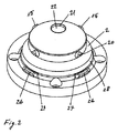
図2は,本発明に係る位置決め・クランプ装置1の斜視図である。図2は,所定プロファイル20を有する4個のロック手段15を基台2の外周上に配置する態様を示すものである。更に,基台2の底部には4個のZ軸方向支持部26が形成されてる。各Z軸方向支持部26の真上には,ブローアウト開口27が形成されている。ブローアウト開口27はそれぞれスロット形状とされ,Z軸方向支持部26に向けられるように下向きに僅かに傾斜して配置されている。基台2に対して相補形状としたワーク用又は工具用ホルダ30の位置決めの間,Z軸方向支持部26はブローアウト開口27からの圧縮空気により清掃される。更に,基台2には円錐状に延在するセンタリング面28を形成する。センタリング面28は,基台2における円筒状の外面に対して厳密に同心的に延在させる。基台2における円筒状の外面とセンタリング面28とを同心的に配置したことにより,プレート又は加工テーブル上における厳密に規定された位置に位置決め・クランプ装置1を位置決めし,かつ,結合させることが可能である。
FIG. 2 is a perspective view of the positioning / clamping apparatus 1 according to the present invention. FIG. 2 shows a mode in which four locking means 15 having a
図3は,本発明に係る位置決め・クランプ装置1の側面図である。基台2は回転対称形状を有し,図6,7に示すように相補形状としたワーク用又は工具用ホルダ30と精密に適合可能とされている。図3には,プレゼンス制御手段も示されている。Z軸方向支持部26内に小孔36が形成されており,Z軸方向支持部26上にホルダ30が存在していない場合に,この小孔36を通じて油圧又は空圧媒体を流す構成とする。小孔36がホルダ30で閉塞されると,媒体の流れが遮断され,ワークが適正に位置決めされたことを,流量モニタ又は圧力モニタによって確認することが可能である。
FIG. 3 is a side view of the positioning / clamping apparatus 1 according to the present invention. The
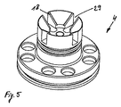
図4a,4bはロック手段15を示す斜視図であり,図5はピストン4を示す斜視図である。ピストン4は開口29を有し,その開口内でロック手段15が半径方向内向き又は外向きに変位可能とされている,これらの図面には,それぞれロック手段15及びピストン4に設けた制御面16,18も示されている。クランプコーン13には,更なる制御面17が設けられている。これらの制御面16,17,18により,ロック手段15がピストン4内及び基台2内において両方向に確実にガイドされるものである。
4a and 4b are perspective views showing the locking means 15, and FIG. 5 is a perspective view showing the
ロック手段15及び基台2の間と,キャップ22及び基台2の間には,何れもシールが配置されていないので,これらの間から空気を流出させ,基台2が相補形状のホルダ30と接触する瞬時に至るまで位置決め・クランプ装置1の表面を掃気することが可能である。
Since no seal is arranged between the locking means 15 and the
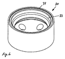
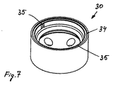
図6,7は,基台2に対して相補形状としたワーク用又は工具用ホルダ30の二通りの変形例を示す斜視図である。大型のワークを位置決めするためには複数の位置決め・クランプ装置1が必要とされる。これら複数の位置決め・クランプ装置のうち,一つはいわゆる「ゼロ点センタリング」を行うものであり,他の一つはワークをX軸方向又はY軸方向に位置決め固定するものである。それ以外の装置は位置決め機能を必要とせず,単にクランプ・保持が行えるもので十分である。図6のホルダ30は,その全周に亘って連続的な円錐面をなすセンタリング面33を有する。この円錐状センタリング面33の直径は,位置決め・クランプ装置1におけるセンタリング面28の直径と厳密に対応している。その結果,遊びがなく,結合すべき装置の変形を最小化した状態での位置決めが可能である。円錐状センタリング面28,33の直径は,材料の弾性限界内での変改のみが生じるように定めるものである。
6 and 7 are perspective views showing two modified examples of the workpiece or
ワーク用又は工具用ホルダ30は,その下向きの周縁部において,センタリング面33の手前に配置された防護リム34を有する。防護リム34は,センタリング面33を汚染及び損傷から防護するものである。図7のホルダ30は,互いに対向する二つのセンタリング面35を有しており,したがってX軸方向又はY軸方向へのセンタリングのみを想定したものである。
The work or
本発明に係る位置決め・クランプ装置1によれば,高負荷下でも使用可能なクランプシステムを実現することが可能である。基台2が大きいセンタリング面28を有し,かつ,ロック手段15がボールを使用せずに作動するため,クランプ力は特定の部位のみにではなく,全面に亘って分配される。精密な位置決めが可能であり,その位置決め精度は耐用寿命の経過後であっても反復的に再現可能である。ロック手段15による保持力は,ボールを使用する装置と対比して,損傷の危険を伴わずに,より増大させることが可能である。
According to the positioning / clamping apparatus 1 according to the present invention, it is possible to realize a clamping system that can be used even under a high load. Since the
1 位置決め・クランプ装置
2 基台
3 受け部
4 ピストン
8 ピン
9 ねじ領域
10 ショルダ領域
11 ヘッド領域
12 スラストワッシャ
13 クランプコーン
15 ロック手段
16,17,18 制御面
21 中心孔
22 キャップ
25 ストッパ
26 Z軸方向の支持部
27 ブローアウト開口
28,33 センタリング面
30 工具用又はワーク用ホルダ
31 円錐面
32 中心孔
34 防護リム
36 プレゼンス制御用の孔
61 基台の外面
DESCRIPTION OF SYMBOLS 1 Positioning /
Claims (17)
・ 基台(2)に円筒状の受け部(3)を形成してピストン(4)を受入れ可能とし,
・ ピストン(4)及びピン(8)の間にクランプコーン(13)を配置し,
・ クランプコーン(13)及びピストン(4)にそれぞれ制御面(17,18)を形成し,
・ クランプコーン(13)及びピストン(4)の制御面(17,18)と協働する更なる制御面(16)をロック手段(15)に形成し,更に,
・ ロック手段(15)を基台(2)に対して半径方向に変位可能に配置したことを特徴とする位置決め・クランプ装置。 A tool or workpiece positioning and clamping device (1) for a base (2), a piston (4) displaceably disposed in the base (2), and a piston (4) At least for locking the connectable pin (8) and the positioning / clamping device (1) with respect to a tool or work holder (30) constructed complementary to the base (2). In a positioning / clamping device (1) comprising one locking means (15),
・ A cylindrical receiving part (3) is formed on the base (2) to accept the piston (4),
A clamp cone (13) is placed between the piston (4) and the pin (8),
-Control surfaces (17, 18) are formed on the clamp cone (13) and the piston (4),
A further control surface (16) cooperating with the control surface (17, 18) of the clamp cone (13) and the piston (4) is formed on the locking means (15);
A positioning / clamping device characterized in that the locking means (15) is arranged to be displaceable in the radial direction with respect to the base (2).
Applications Claiming Priority (3)
| Application Number | Priority Date | Filing Date | Title |
|---|---|---|---|
| EP05019647.6 | 2005-09-09 | ||
| EP05019647A EP1762330B1 (en) | 2005-09-09 | 2005-09-09 | Positioning and tensioning device for tools and/or workpieces |
| PCT/EP2006/005586 WO2007031123A1 (en) | 2005-09-09 | 2006-06-10 | Positioning and clamping device for tools and/or workpieces |
Publications (2)
| Publication Number | Publication Date |
|---|---|
| JP2009506902A true JP2009506902A (en) | 2009-02-19 |
| JP5027133B2 JP5027133B2 (en) | 2012-09-19 |
Family
ID=35840157
Family Applications (1)
| Application Number | Title | Priority Date | Filing Date |
|---|---|---|---|
| JP2008529480A Expired - Fee Related JP5027133B2 (en) | 2005-09-09 | 2006-06-10 | Positioning and clamping device for tools or workpieces |
Country Status (7)
| Country | Link |
|---|---|
| US (1) | US8061717B2 (en) |
| EP (1) | EP1762330B1 (en) |
| JP (1) | JP5027133B2 (en) |
| CN (1) | CN101253020B (en) |
| AT (1) | ATE401990T1 (en) |
| DE (1) | DE502005004823D1 (en) |
| WO (1) | WO2007031123A1 (en) |
Cited By (2)
| Publication number | Priority date | Publication date | Assignee | Title |
|---|---|---|---|---|
| CN105014427A (en) * | 2015-07-16 | 2015-11-04 | 佛山市普拉迪数控科技有限公司 | Work fixture for Z-shaped ship air conditioner beam |
| CN114101746A (en) * | 2021-12-20 | 2022-03-01 | 陈颖桢 | Machining equipment for punching arc workpiece and using method thereof |
Families Citing this family (15)
| Publication number | Priority date | Publication date | Assignee | Title |
|---|---|---|---|---|
| ES2300903T3 (en) * | 2005-07-09 | 2008-06-16 | System 3R International Ab | TIGHTENING DEVICE FOR A TOOL OR A WORK PIECE. |
| CZ19793U1 (en) | 2009-05-25 | 2009-06-29 | Koran, Spol.S R.O. | Clamping device for machine tools |
| DE102010013911B4 (en) * | 2010-04-01 | 2013-07-25 | Schunk Gmbh & Co. Kg Spann- Und Greiftechnik | Clamping module, in particular zero point clamping module |
| KR20110135587A (en) * | 2010-06-11 | 2011-12-19 | 두산인프라코어 주식회사 | Clamping device of cross rail of door type machine |
| CN101870066B (en) * | 2010-06-22 | 2011-08-31 | 苏州纽威机床设计研究院有限公司 | Adjustor with clamping and positioning functions |
| CN103302523A (en) * | 2013-05-21 | 2013-09-18 | 苏州惠瑞自动化集成有限公司 | Automatic wire fixture capable of limiting pressure |
| CZ309713B6 (en) * | 2013-08-20 | 2023-08-16 | Erowa Ag | Clamping device |
| CN103447850A (en) * | 2013-08-23 | 2013-12-18 | 无锡威孚精密机械制造有限责任公司 | Bearing end cap machining clamp |
| US20150185104A1 (en) * | 2014-01-02 | 2015-07-02 | George P. Widas, III | System for Calibrating a Tribometer Test Foot |
| CN104440324B (en) * | 2014-12-29 | 2017-01-25 | 安阳工学院 | Clamp for differential mechanism shell inner sphere coarse and fine reaming machine tool |
| CN105382587A (en) * | 2015-12-18 | 2016-03-09 | 天津天海同步科技有限公司 | Self-centering milling die |
| CN110421395B (en) * | 2019-09-01 | 2024-05-24 | 苏州速易德工业装备系统有限公司 | High-precision flexible zero point positioning system |
| CN110421373B (en) * | 2019-09-01 | 2024-05-28 | 苏州速易德工业装备系统有限公司 | Zero point positioning system with mechanical locking double-sided constraint positioning function |
| CN116037563B (en) * | 2023-01-13 | 2023-06-06 | 北京航臻科技有限公司 | Chip removing device for zero point positioning system |
| CN117564965A (en) * | 2023-11-30 | 2024-02-20 | 重庆速腾机械制造有限公司 | A hydraulic vertical angle device |
Citations (4)
| Publication number | Priority date | Publication date | Assignee | Title |
|---|---|---|---|---|
| JPH1058258A (en) * | 1996-06-17 | 1998-03-03 | Certa Ag | Clamp device for clamping workpiece or tool in proper position |
| JP2004209607A (en) * | 2003-01-07 | 2004-07-29 | Kosmek Ltd | Alignment drive mechanism and positioning device provided with the mechanism |
| JP2004255484A (en) * | 2003-02-25 | 2004-09-16 | Pascal Engineering Corp | Clamping device |
| JP2005040922A (en) * | 2003-07-25 | 2005-02-17 | Kosmek Ltd | Clamping device |
Family Cites Families (13)
| Publication number | Priority date | Publication date | Assignee | Title |
|---|---|---|---|---|
| US1566370A (en) * | 1925-02-20 | 1925-12-22 | John W Briscoe | Chuck |
| US1873515A (en) * | 1930-11-03 | 1932-08-23 | Charles H Warren | End locating device |
| US2535246A (en) * | 1947-02-10 | 1950-12-26 | Novi Equipment Co | Chuck assembly |
| US3086783A (en) * | 1960-08-17 | 1963-04-23 | United States Steel Corp | Expanding mandrel for machining pipe ends |
| US3978767A (en) * | 1974-07-11 | 1976-09-07 | Joel C. Levin | Automatic center holding fixture for an annular workpiece |
| US4534116A (en) * | 1983-08-26 | 1985-08-13 | Lenzar Optics Corporation | Adapter for boresight telescope |
| DE19636375A1 (en) * | 1996-09-09 | 1998-03-12 | Emil Stark | Quick release for a pallet under chip flight |
| ATE280011T1 (en) * | 1999-07-14 | 2004-11-15 | Erowa Ag | DEVICE FOR POSITION-DEFINED CLAMPING OF A WORKPIECE IN THE WORKING AREA OF A PROCESSING MACHINE |
| DE10116229A1 (en) | 2001-04-02 | 2002-10-10 | Mecatool Ag Flawil | Device for releasably holding workpieces on machining equipment |
| DE10117485B4 (en) * | 2001-04-07 | 2004-12-02 | Schunk Gmbh & Co. Kg Fabrik Für Spann- Und Greifwerkzeuge | tensioning device |
| EP1302278A1 (en) * | 2001-10-12 | 2003-04-16 | Kabushiki Kaisha Kosmek | Clamping apparatus |
| DE50203354D1 (en) * | 2002-09-09 | 2005-07-14 | Hermle Berthold Maschf Ag | Clamping device for clamping two parts together |
| JP4174453B2 (en) * | 2004-01-28 | 2008-10-29 | キヤノン株式会社 | Disc chuck mechanism |
-
2005
- 2005-09-09 DE DE502005004823T patent/DE502005004823D1/en not_active Expired - Lifetime
- 2005-09-09 AT AT05019647T patent/ATE401990T1/en active
- 2005-09-09 EP EP05019647A patent/EP1762330B1/en not_active Expired - Lifetime
-
2006
- 2006-06-10 WO PCT/EP2006/005586 patent/WO2007031123A1/en not_active Ceased
- 2006-06-10 US US12/065,907 patent/US8061717B2/en not_active Expired - Fee Related
- 2006-06-10 CN CN2006800321415A patent/CN101253020B/en not_active Expired - Fee Related
- 2006-06-10 JP JP2008529480A patent/JP5027133B2/en not_active Expired - Fee Related
Patent Citations (4)
| Publication number | Priority date | Publication date | Assignee | Title |
|---|---|---|---|---|
| JPH1058258A (en) * | 1996-06-17 | 1998-03-03 | Certa Ag | Clamp device for clamping workpiece or tool in proper position |
| JP2004209607A (en) * | 2003-01-07 | 2004-07-29 | Kosmek Ltd | Alignment drive mechanism and positioning device provided with the mechanism |
| JP2004255484A (en) * | 2003-02-25 | 2004-09-16 | Pascal Engineering Corp | Clamping device |
| JP2005040922A (en) * | 2003-07-25 | 2005-02-17 | Kosmek Ltd | Clamping device |
Cited By (3)
| Publication number | Priority date | Publication date | Assignee | Title |
|---|---|---|---|---|
| CN105014427A (en) * | 2015-07-16 | 2015-11-04 | 佛山市普拉迪数控科技有限公司 | Work fixture for Z-shaped ship air conditioner beam |
| CN114101746A (en) * | 2021-12-20 | 2022-03-01 | 陈颖桢 | Machining equipment for punching arc workpiece and using method thereof |
| CN114101746B (en) * | 2021-12-20 | 2024-02-02 | 陈颖桢 | Processing equipment for punching circular arc workpiece and application method thereof |
Also Published As
| Publication number | Publication date |
|---|---|
| CN101253020B (en) | 2013-01-09 |
| JP5027133B2 (en) | 2012-09-19 |
| EP1762330B1 (en) | 2008-07-23 |
| CN101253020A (en) | 2008-08-27 |
| WO2007031123A1 (en) | 2007-03-22 |
| EP1762330A1 (en) | 2007-03-14 |
| DE502005004823D1 (en) | 2008-09-04 |
| ATE401990T1 (en) | 2008-08-15 |
| US20080237958A1 (en) | 2008-10-02 |
| US8061717B2 (en) | 2011-11-22 |
Similar Documents
| Publication | Publication Date | Title |
|---|---|---|
| JP5027133B2 (en) | Positioning and clamping device for tools or workpieces | |
| TWI618599B (en) | Clamping fixture | |
| US8613434B2 (en) | Work pallet positioning and fixing device | |
| JP4167515B2 (en) | Clamp device with clamp chuck | |
| JP5064622B2 (en) | Clamping device | |
| JP5690275B2 (en) | Clamping device | |
| KR102194587B1 (en) | Clamping chuck with integrated drawbar | |
| JPH1058258A (en) | Clamp device for clamping workpiece or tool in proper position | |
| JP2012066373A (en) | Clamp device | |
| TW202027903A (en) | Clamp device | |
| JP4954899B2 (en) | Positioning device and positioning system | |
| EP1810777A1 (en) | Coupler for supporting body and movable body | |
| JPH11285944A (en) | Clamp device for fixing mounting nipple to clamp plate | |
| WO2024070394A1 (en) | Clamp device | |
| JP2003181730A (en) | Clamping device | |
| US20170341193A1 (en) | Operator-friendly Dead-length Quick-set Workholding Collet & Chuck Docking Station | |
| US10987771B2 (en) | Air rest button | |
| JP2001096435A (en) | Equipment for detecting incoming objects | |
| JP2018069423A (en) | Center device | |
| JP4851218B2 (en) | Positioning device | |
| KR20230125740A (en) | Tool port | |
| HK1082932A1 (en) | Clamping apparatus with a chunk and a pallet releasably attachable thereto | |
| HK1082932B (en) | Clamping apparatus with a chunk and a pallet releasably attachable thereto |
Legal Events
| Date | Code | Title | Description |
|---|---|---|---|
| A621 | Written request for application examination |
Free format text: JAPANESE INTERMEDIATE CODE: A621 Effective date: 20090414 |
|
| RD04 | Notification of resignation of power of attorney |
Free format text: JAPANESE INTERMEDIATE CODE: A7424 Effective date: 20090414 |
|
| A131 | Notification of reasons for refusal |
Free format text: JAPANESE INTERMEDIATE CODE: A131 Effective date: 20110906 |
|
| A601 | Written request for extension of time |
Free format text: JAPANESE INTERMEDIATE CODE: A601 Effective date: 20111129 |
|
| A602 | Written permission of extension of time |
Free format text: JAPANESE INTERMEDIATE CODE: A602 Effective date: 20111206 |
|
| A521 | Request for written amendment filed |
Free format text: JAPANESE INTERMEDIATE CODE: A523 Effective date: 20120206 |
|
| A131 | Notification of reasons for refusal |
Free format text: JAPANESE INTERMEDIATE CODE: A131 Effective date: 20120228 |
|
| RD03 | Notification of appointment of power of attorney |
Free format text: JAPANESE INTERMEDIATE CODE: A7423 Effective date: 20120419 |
|
| A521 | Request for written amendment filed |
Free format text: JAPANESE INTERMEDIATE CODE: A523 Effective date: 20120424 |
|
| A521 | Request for written amendment filed |
Free format text: JAPANESE INTERMEDIATE CODE: A821 Effective date: 20120419 |
|
| TRDD | Decision of grant or rejection written | ||
| A01 | Written decision to grant a patent or to grant a registration (utility model) |
Free format text: JAPANESE INTERMEDIATE CODE: A01 Effective date: 20120605 |
|
| A01 | Written decision to grant a patent or to grant a registration (utility model) |
Free format text: JAPANESE INTERMEDIATE CODE: A01 |
|
| A61 | First payment of annual fees (during grant procedure) |
Free format text: JAPANESE INTERMEDIATE CODE: A61 Effective date: 20120621 |
|
| FPAY | Renewal fee payment (event date is renewal date of database) |
Free format text: PAYMENT UNTIL: 20150629 Year of fee payment: 3 |
|
| R150 | Certificate of patent or registration of utility model |
Ref document number: 5027133 Country of ref document: JP Free format text: JAPANESE INTERMEDIATE CODE: R150 Free format text: JAPANESE INTERMEDIATE CODE: R150 |
|
| R250 | Receipt of annual fees |
Free format text: JAPANESE INTERMEDIATE CODE: R250 |
|
| S111 | Request for change of ownership or part of ownership |
Free format text: JAPANESE INTERMEDIATE CODE: R313113 |
|
| R350 | Written notification of registration of transfer |
Free format text: JAPANESE INTERMEDIATE CODE: R350 |
|
| R250 | Receipt of annual fees |
Free format text: JAPANESE INTERMEDIATE CODE: R250 |
|
| R250 | Receipt of annual fees |
Free format text: JAPANESE INTERMEDIATE CODE: R250 |
|
| R250 | Receipt of annual fees |
Free format text: JAPANESE INTERMEDIATE CODE: R250 |
|
| R250 | Receipt of annual fees |
Free format text: JAPANESE INTERMEDIATE CODE: R250 |
|
| R250 | Receipt of annual fees |
Free format text: JAPANESE INTERMEDIATE CODE: R250 |
|
| R250 | Receipt of annual fees |
Free format text: JAPANESE INTERMEDIATE CODE: R250 |
|
| LAPS | Cancellation because of no payment of annual fees |