JP2010054848A - Transfer electric field forming member, transfer device and image forming apparatus - Google Patents
Transfer electric field forming member, transfer device and image forming apparatus Download PDFInfo
- Publication number
- JP2010054848A JP2010054848A JP2008220282A JP2008220282A JP2010054848A JP 2010054848 A JP2010054848 A JP 2010054848A JP 2008220282 A JP2008220282 A JP 2008220282A JP 2008220282 A JP2008220282 A JP 2008220282A JP 2010054848 A JP2010054848 A JP 2010054848A
- Authority
- JP
- Japan
- Prior art keywords
- transfer
- electric field
- transfer electric
- toner
- roller
- Prior art date
- Legal status (The legal status is an assumption and is not a legal conclusion. Google has not performed a legal analysis and makes no representation as to the accuracy of the status listed.)
- Pending
Links
Images



Landscapes
- Electrostatic Charge, Transfer And Separation In Electrography (AREA)
- Rolls And Other Rotary Bodies (AREA)
Abstract
【課題】トナー像を担持する中間転写ベルト、感光体ベルト等の無端ベルト状の回転部材を備えた複写機、ファクシミリ、プリンタ等の画像形成装置に備えられ、回転部材上のトナー像を記録媒体に転写するための転写電界を形成する転写電界形成部材により、非平滑紙におけるベタ画像ボソツキの防止、抑制を図る。
【解決手段】無端ベルト状の回転部材11の裏面に当接した弾性層72aを有し、回転部材11の表面側の対向部材5との間に、トナー像を記録媒体Sに転写するための転写電界を形成する転写電界形成部材72であって、弾性層72aが、回転部材11の厚さより小さく、回転部材11に担持されるトナー像を構成するトナーの体積平均粒径より大きな体積平均粒径を有する微粒子72cを含有している転写電界形成部材72、これを備えた転写装置19及びこれらを備えた画像形成装置。
【選択図】図4Provided in an image forming apparatus such as a copying machine, a facsimile, or a printer having an endless belt-like rotating member such as an intermediate transfer belt or a photosensitive belt carrying a toner image, and recording the toner image on the rotating member on a recording medium By using a transfer electric field forming member that forms a transfer electric field for transferring to a non-smooth paper, solid image blur is prevented and suppressed.
An elastic layer 72a is in contact with the back surface of an endless belt-like rotating member 11 and is used to transfer a toner image to a recording medium S with a facing member 5 on the front surface side of the rotating member 11. A transfer electric field forming member 72 for forming a transfer electric field, in which the elastic layer 72a is smaller than the thickness of the rotating member 11 and larger than the volume average particle diameter of the toner constituting the toner image carried on the rotating member 11. A transfer electric field forming member 72 containing fine particles 72c having a diameter, a transfer device 19 including the same, and an image forming apparatus including these.
[Selection] Figure 4
Description
本発明は、複写機、ファクシミリ、プリンタ等の画像形成装置であって、特に、表面にトナー像を担持する中間転写ベルト、感光体ベルト等の無端ベルト状の回転部材を備えた画像形成装置に備えられ、回転部材の表面から用紙等の記録媒体にトナー像を転写する転写装置に備えられた、転写を行なうための転写電界を形成する転写電界形成部材、これを備えたかかる転写装置、及び、これらを備えたかかる画像形成装置に関する。 The present invention relates to an image forming apparatus such as a copying machine, a facsimile, or a printer, and more particularly to an image forming apparatus provided with an endless belt-like rotating member such as an intermediate transfer belt or a photosensitive belt that carries a toner image on its surface. A transfer electric field forming member for forming a transfer electric field for transfer, provided in a transfer device for transferring a toner image from the surface of the rotating member to a recording medium such as paper, and such a transfer device equipped with the transfer electric field forming member; The present invention also relates to such an image forming apparatus.
複写機、ファクシミリ、プリンタ等の画像形成装置は一般に、像担持体に担持されたトナー像を転写するための転写装置を備えている(たとえば、〔特許文献1〕ないし〔特許文献21〕参照)。転写装置としては、従来より、転写を良好に行うための種々の構成が提案されており、たとえば中間転写ベルト上に担持されたトナー像を、非平滑紙を含む種々の用紙に安定して転写するために超音波振動を利用する技術も提案されている(たとえば、〔特許文献1〕参照)。なお、硬質の樹脂材料、セラミック素材、ガラスビーズが種々知られており、これらについて記載した文献も公開されている(たとえば、〔特許文献22〕ないし〔特許文献25〕参照)。 Image forming apparatuses such as copying machines, facsimile machines, and printers generally include a transfer device for transferring a toner image carried on an image carrier (see, for example, [Patent Document 1] to [Patent Document 21]). . Conventionally, various configurations have been proposed as a transfer device for good transfer. For example, a toner image carried on an intermediate transfer belt can be stably transferred onto various papers including non-smooth paper. In order to achieve this, a technique using ultrasonic vibration has also been proposed (see, for example, [Patent Document 1]). Various hard resin materials, ceramic materials, and glass beads are known, and literatures describing these are also disclosed (see, for example, [Patent Literature 22] to [Patent Literature 25]).
しかし、中間転写ベルト上に担持されたトナー像を種々の用紙に安定して転写するために超音波振動を利用する技術では、中間転写ベルトのトナー不在の領域まで超音波振動が伝達されることがあり無駄が多い等の問題があったため、超音波振動を用いずに種々の用紙に安定して転写を行う技術を提供する必要がある。かかる技術は、トナーを担持した部材が中間転写ベルトに限らず感光体ベルト等の場合であっても必要である。特に、非平滑紙といわれるような、表面に凹凸のある用紙に、高濃度の画像が広域にわたって形成されるいわゆるベタ画像を転写するときには、かかる凹凸に起因して所々に濃淡のムラが発生する、いわゆるベタ画像ボソツキといわれる不良画像が発生するため、このベタ画像ボソツキの防止、抑制を図る技術の開発が待たれているところであった。 However, in the technology that uses ultrasonic vibration to stably transfer the toner image carried on the intermediate transfer belt to various papers, the ultrasonic vibration is transmitted to the toner-free region of the intermediate transfer belt. Therefore, it is necessary to provide a technique for stably transferring to various papers without using ultrasonic vibration. Such a technique is necessary even when the member carrying the toner is not limited to the intermediate transfer belt but a photosensitive belt or the like. In particular, when a so-called solid image in which a high-density image is formed over a wide area is transferred onto a sheet having unevenness on the surface, which is called non-smooth paper, unevenness in density occurs in some places due to the unevenness. Since a defective image called so-called solid image blur occurs, development of a technique for preventing and suppressing the solid image blur has been awaited.
本発明は、複写機、ファクシミリ、プリンタ等の画像形成装置であって、特に、表面にトナー像を担持する中間転写ベルト、感光体ベルト等の無端ベルト状の回転部材を備えた画像形成装置に備えられ、回転部材の表面から用紙等の記録媒体にトナー像を転写する転写装置に備えられた、転写を行なうための転写電界を形成する、非平滑紙におけるベタ画像ボソツキの防止、抑制を図った転写電界形成部材、これを備えたかかる転写装置、及び、これらを備えたかかる画像形成装置を提供することを目的とする。 The present invention relates to an image forming apparatus such as a copying machine, a facsimile, or a printer, and more particularly to an image forming apparatus provided with an endless belt-like rotating member such as an intermediate transfer belt or a photosensitive belt that carries a toner image on its surface. The transfer device provided in the transfer device for transferring the toner image from the surface of the rotating member to a recording medium such as paper forms a transfer electric field for transfer and prevents and suppresses solid image blur in non-smooth paper. Another object of the present invention is to provide a transfer electric field forming member, such a transfer device including the same, and such an image forming device including these.
上記目的を達成するため、請求項1記載の発明は、表面にトナー像を担持する無端ベルト状の回転部材の裏面から同回転部材に当接した弾性層を有し、同回転部材を挟んで同回転部材の表面側に対向配置された対向部材との間に、同回転部材の表面に担持されたトナー像を記録媒体に転写するための転写電界を形成する転写電界形成部材であって、前記弾性層が、同回転部材の厚さより小さく、同回転部材に担持されるトナー像を構成するトナーの体積平均粒径より大きな体積平均粒径を有する微粒子を含有している転写電界形成部材にある。
In order to achieve the above object, the invention according to
請求項2記載の発明は、請求項1記載の転写電界形成部材において、前記微粒子の体積平均粒径が、前記回転部材に担持されるトナー像を構成する画素の最小径より小さいことを特徴とする。 According to a second aspect of the present invention, in the transfer electric field forming member according to the first aspect, the volume average particle diameter of the fine particles is smaller than the minimum diameter of the pixels constituting the toner image carried on the rotating member. To do.
請求項3記載の発明は、請求項1又は2記載の転写電界形成部材において、前記微粒子が、前記弾性層の、前記回転部材の裏面側に偏在していることを特徴とする。 According to a third aspect of the present invention, in the transfer electric field forming member according to the first or second aspect, the fine particles are unevenly distributed on the back surface side of the rotating member of the elastic layer.
請求項4記載の発明は、請求項1ないし3の何れか1つに記載の転写電界形成部材において、前記微粒子の硬度が、前記弾性層の硬度より高いことを特徴とする。 According to a fourth aspect of the present invention, in the transfer electric field forming member according to any one of the first to third aspects, the hardness of the fine particles is higher than the hardness of the elastic layer.
請求項5記載の発明は、請求項1ないし4の何れか1つに記載の転写電界形成部材において、前記弾性層の少なくとも一部が発泡体であることを特徴とする。 According to a fifth aspect of the present invention, in the transfer electric field forming member according to any one of the first to fourth aspects, at least a part of the elastic layer is a foam.
請求項6記載の発明は、請求項1ないし5の何れか1つに記載の転写電界形成部材において、前記弾性層の硬度が、前記対向部材の表層の硬度以下であることを特徴とする。 According to a sixth aspect of the present invention, in the transfer electric field forming member according to any one of the first to fifth aspects, the hardness of the elastic layer is equal to or less than the hardness of the surface layer of the opposing member.
請求項7記載の発明は、請求項1ないし6の何れか1つに記載の転写電界形成部材において、前記微粒子が、樹脂、セラミック、ガラスから選択される材質からなることを特徴とする。 According to a seventh aspect of the present invention, in the transfer electric field forming member according to any one of the first to sixth aspects, the fine particles are made of a material selected from resin, ceramic and glass.
請求項8記載の発明は、請求項1ないし7の何れか1つに記載の転写電界形成部材において、前記弾性層の表面の無負荷時の算術平均粗さが、前記回転部材に担持されるトナー像を構成するトナーの体積平均粒径より小さいことを特徴とする。 According to an eighth aspect of the present invention, in the transfer electric field forming member according to any one of the first to seventh aspects, an arithmetic average roughness of the surface of the elastic layer when no load is applied is carried by the rotating member. It is characterized by being smaller than the volume average particle diameter of the toner constituting the toner image.
請求項9記載の発明は、請求項1ないし8の何れか1つに記載の転写電界形成部材と、前記対向部材とを有し、同転写電界形成部材と同対向部材との少なくとも一方が、前記転写電界を形成するための電圧を印加されるバイアス印加部材である転写装置にある。
The invention according to
請求項10記載の発明は、請求項9記載の転写装置において、前記対向部材の表面の算術平均粗さが、前記回転部材に担持されるトナー像を構成するトナーの体積平均粒径より小さいことを特徴とする。 According to a tenth aspect of the present invention, in the transfer device according to the ninth aspect, the arithmetic average roughness of the surface of the facing member is smaller than the volume average particle diameter of the toner constituting the toner image carried on the rotating member. It is characterized by.
請求項11記載の発明は、請求項1ないし8の何れか1つに記載の転写電界形成部材、又は、請求項9又は10記載の転写装置と、前記回転部材とを有する画像形成装置にある。 An eleventh aspect of the invention is an image forming apparatus comprising the transfer electric field forming member according to any one of the first to eighth aspects, or the transfer device according to the ninth or tenth aspect and the rotating member. .
本発明は、表面にトナー像を担持する無端ベルト状の回転部材の裏面から同回転部材に当接した弾性層を有し、同回転部材を挟んで同回転部材の表面側に対向配置された対向部材との間に、同回転部材の表面に担持されたトナー像を記録媒体に転写するための転写電界を形成する転写電界形成部材であって、前記弾性層が、同回転部材の厚さより小さく、同回転部材に担持されるトナー像を構成するトナーの体積平均粒径より大きな体積平均粒径を有する微粒子を含有している転写電界形成部材にあるので、記録媒体が非平滑紙である場合でも、その表面に対する回転部材の密着度を高め、非平滑紙におけるベタ画像ボソツキを防止ないし抑制することができ、良好な転写及びこれによる良好な画像形成に寄与することができる転写電界形成部材を提供することができる。 The present invention has an elastic layer in contact with the rotating member from the back surface of the endless belt-shaped rotating member carrying a toner image on the surface, and is disposed opposite to the surface side of the rotating member with the rotating member interposed therebetween. A transfer electric field forming member for forming a transfer electric field for transferring a toner image carried on the surface of the rotating member to a recording medium between the opposing member, wherein the elastic layer has a thickness greater than that of the rotating member. The recording medium is non-smooth paper because it is in a transfer electric field forming member that is small and contains fine particles having a volume average particle size larger than the volume average particle size of the toner constituting the toner image carried on the rotating member. Even in this case, it is possible to increase the degree of adhesion of the rotating member to the surface, prevent or suppress solid image blurring on non-smooth paper, and form a transfer electric field that can contribute to good transfer and good image formation by this. It is possible to provide the wood.
前記微粒子の体積平均粒径が、前記回転部材に担持されるトナー像を構成する画素の最小径より小さいこととすれば、記録媒体が非平滑紙である場合でも、その表面に対する回転部材の密着度を、微粒子の体積平均粒径をかかる条件にすることで高め、また最小画素レベルの面積で転写圧を均等にすることにより、非平滑紙におけるベタ画像ボソツキを防止ないし抑制することができ、良好な転写及びこれによる良好な画像形成に寄与することができる転写電界形成部材を提供することができる。 If the volume average particle diameter of the fine particles is smaller than the minimum diameter of the pixels constituting the toner image carried on the rotating member, even if the recording medium is non-smooth paper, the rotating member adheres to the surface thereof. By increasing the degree by setting the volume average particle size of the fine particles to such a condition, and by equalizing the transfer pressure with the area of the minimum pixel level, it is possible to prevent or suppress the solid image blur in the non-smooth paper, It is possible to provide a transfer electric field forming member that can contribute to good transfer and good image formation.
前記微粒子が、前記弾性層の、前記回転部材の裏面側に偏在していることとすれば、記録媒体が非平滑紙である場合でも、その表面に対する回転部材の密着度を、微粒子の偏在により効果的に高め、非平滑紙におけるベタ画像ボソツキを防止ないし抑制することができ、良好な転写及びこれによる良好な画像形成に寄与することができる転写電界形成部材を提供することができる。 If the fine particles are unevenly distributed on the back surface side of the rotating member of the elastic layer, even when the recording medium is non-smooth paper, the degree of adhesion of the rotating member to the surface is determined by the uneven distribution of the fine particles. It is possible to provide a transfer electric field forming member that can effectively increase and prevent or suppress solid image blur in non-smooth paper and contribute to good transfer and good image formation.
前記微粒子の硬度が、前記弾性層の硬度より高いこととすれば、記録媒体が非平滑紙である場合でも、その表面に対する回転部材の密着度を、微粒子の硬度をかかる条件にすることによって効果的に且つ安定して高め、非平滑紙におけるベタ画像ボソツキを防止ないし抑制することができるとともに転写電界形成部剤の寿命を向上し、長期にわたって良好な転写及びこれによる長期にわたる良好な画像形成に寄与することができる転写電界形成部材を提供することができる。 If the hardness of the fine particles is higher than the hardness of the elastic layer, even if the recording medium is non-smooth paper, the degree of adhesion of the rotating member with respect to the surface of the recording medium is adjusted by taking the hardness of the fine particles into account. It is possible to improve the stability and stability of the non-smooth paper to prevent or suppress the solid image blur and improve the life of the transfer electric field forming agent. It is possible to provide a transfer electric field forming member that can contribute.
前記弾性層の少なくとも一部が発泡体であることとすれば、記録媒体が非平滑紙である場合でも、その表面に対する回転部材の密着度を、発泡体によって効果的に且つ安定して高め、非平滑紙におけるベタ画像ボソツキを防止ないし抑制することができ、良好な転写及びこれによる良好な画像形成に寄与することができる転写電界形成部材を提供することができる。 If at least a part of the elastic layer is a foam, even when the recording medium is non-smooth paper, the adhesion of the rotating member to the surface thereof is effectively and stably increased by the foam, It is possible to provide a transfer electric field forming member capable of preventing or suppressing solid image blur in non-smooth paper and contributing to good transfer and good image formation.
前記弾性層の硬度が、前記対向部材の表層の硬度以下であることとすれば、記録媒体が非平滑紙である場合でも、その表面に対する回転部材の密着度を、弾性層の硬度をかかる条件にすることによって効果的に且つ安定して高め、非平滑紙におけるベタ画像ボソツキを防止ないし抑制することができ、良好な転写及びこれによる良好な画像形成に寄与することができる転写電界形成部材を提供することができる。 If the hardness of the elastic layer is equal to or less than the hardness of the surface layer of the opposing member, even when the recording medium is non-smooth paper, the degree of adhesion of the rotating member to the surface is determined by the condition that the hardness of the elastic layer is applied. A transfer electric field forming member that can effectively and stably enhance, prevent or suppress solid image blur in non-smooth paper, and contribute to good transfer and good image formation by this. Can be provided.
前記微粒子が、樹脂、セラミック、ガラスから選択される材質からなることとすれば、記録媒体が非平滑紙である場合でも、その表面に対する回転部材の密着度を、微粒子の材質をかかる材質にすることによって効果的に且つ安定して高め、非平滑紙におけるベタ画像ボソツキを防止ないし抑制することができ、良好な転写及びこれによる良好な画像形成に寄与することができる転写電界形成部材を提供することができる。 If the fine particles are made of a material selected from resin, ceramic, and glass, even when the recording medium is non-smooth paper, the degree of adhesion of the rotating member to the surface thereof is made the material of the fine particles. There is provided a transfer electric field forming member that can effectively and stably enhance, prevent or suppress solid image blur on non-smooth paper, and contribute to good transfer and good image formation. be able to.
前記弾性層の表面の無負荷時の算術平均粗さが、前記回転部材に担持されるトナー像を構成するトナーの体積平均粒径より小さいこととすれば、記録媒体が非平滑紙である場合でも、その表面に対する回転部材の密着度を、弾性層表面の算術平均粗さをかかる条件にすることによって効果的に且つ安定して高め、非平滑紙におけるベタ画像ボソツキを防止ないし抑制することができ、良好な転写及びこれによる良好な画像形成に寄与することができる転写電界形成部材を提供することができる。 When the arithmetic average roughness of the surface of the elastic layer under no load is smaller than the volume average particle diameter of the toner constituting the toner image carried on the rotating member, the recording medium is non-smooth paper However, the degree of adhesion of the rotating member to the surface can be effectively and stably increased by setting the arithmetic average roughness of the elastic layer surface to prevent or suppress solid image blurring on non-smooth paper. It is possible to provide a transfer electric field forming member that can contribute to good transfer and good image formation.
本発明は、かかる転写電界形成部材と、前記対向部材とを有し、同転写電界形成部材と同対向部材との少なくとも一方が、前記転写電界を形成するための電圧を印加されるバイアス印加部材である転写装置にあるので、記録媒体が非平滑紙である場合でも、その表面に対する回転部材の密着度を高め、非平滑紙におけるベタ画像ボソツキを防止ないし抑制することができ、これによって転写性能を向上することができ、また良好な画像形成に寄与することができる転写装置を提供することができる。 The present invention has such a transfer electric field forming member and the counter member, and at least one of the transfer electric field forming member and the counter member is applied with a voltage for forming the transfer electric field. Therefore, even when the recording medium is non-smooth paper, the adhesion of the rotating member to the surface of the recording medium can be increased, and solid image blurring on the non-smooth paper can be prevented or suppressed. Can be improved, and a transfer apparatus that can contribute to good image formation can be provided.
前記対向部材の表面の算術平均粗さが、前記回転部材に担持されるトナー像を構成するトナーの体積平均粒径より小さいこととすれば、記録媒体が非平滑紙である場合でも、その表面に対する回転部材の密着度を、対向部材表面の算術平均粗さをかかる条件にすることによって効果的に且つ安定して高め、非平滑紙におけるベタ画像ボソツキを防止ないし抑制することができ、これによって転写性能が向上し、また良好な画像形成に寄与することができる転写装置を提供することができる。 If the arithmetic average roughness of the surface of the opposing member is smaller than the volume average particle diameter of the toner constituting the toner image carried on the rotating member, even if the recording medium is non-smooth paper, the surface thereof The degree of adhesion of the rotating member with respect to the surface of the opposing member is effectively and stably increased by making the arithmetic average roughness of the opposing member into such a condition, and solid image blurring in non-smooth paper can be prevented or suppressed. It is possible to provide a transfer device that can improve transfer performance and contribute to good image formation.
本発明は、かかる転写電界形成部材、又は、かかる転写装置と、前記回転部材とを有する画像形成装置にあるので、記録媒体が非平滑紙である場合でも、その表面に対する回転部材の密着度を高め、非平滑紙におけるベタ画像ボソツキを防止ないし抑制することができ、これによって転写性能が向上し、形成画像の質が向上した画像形成装置を提供することができる。 Since the present invention resides in such a transfer electric field forming member or an image forming apparatus having such a transfer device and the rotating member, even when the recording medium is non-smooth paper, the degree of adhesion of the rotating member to the surface thereof In addition, it is possible to prevent or suppress the solid image blur in the non-smooth paper, thereby providing an image forming apparatus with improved transfer performance and improved quality of the formed image.
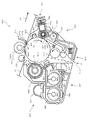
図1に本発明を適用した画像形成装置の概略を示す。画像形成装置100は、カラー画像を形成可能であるカラーレーザプリンタであるが、他のタイプのプリンタ、ファクシミリ、複写機、複写機とプリンタとの複合機等、他の画像形成装置であっても良い。画像形成装置100は、外部から受信した画像情報に対応する画像信号に基づき画像形成処理を行なう。画像形成装置100は、一般にコピー等に用いられる普通紙の他、OHPシート等の樹脂フィルムや、カード、ハガキ等の厚紙や、封筒、非平滑紙等の何れをも最終転写部材としてのシート状の記録媒体として画像形成を行なうことが可能である。なお画像形成措置100に使用可能な記録媒体の種類を図6に例示する。
FIG. 1 shows an outline of an image forming apparatus to which the present invention is applied. The
画像形成装置100は、イエロー、マゼンタ、シアン、ブラックの各色に色分解された色にそれぞれ対応する像としての画像を形成可能な像担持体としての感光体ドラム20Y、20C、20M、20BKを並設したタンデム構造、言い換えるとタンデム方式を採用している。各符号の数字の後に付されたY、M、C、BKは、イエロー、マゼンタ、シアン、黒用の部材であることを示している。
The
表面移動部材たる感光体ドラム20Y、20C、20M、20BKは、画像形成装置100の本体99の内部のほぼ中央部に配設された無端ベルト状の回転部材である中間転写体としての中間転写ベルトたる転写ベルト11の外周面側すなわち作像面側に当接している。
The
転写ベルト11は、各感光体ドラム20Y、20C、20M、20BKに対向配置されこれらに対峙しながら矢印A1方向に移動可能となっている。各感光体ドラム感光体ドラム20Y、20C、20M、20BKは、A1方向の上流側からこの順で並んでいる。
The
各感光体ドラム20Y、20C、20M、20BKに形成された可視像すなわちトナー像は、矢印A1方向に移動する転写ベルト11の表面に対しそれぞれ重畳転写されて担持され、その後、記録媒体である転写紙Sに一括転写されるようになっている。よって、画像形成装置100は中間転写方式の画像形成装置となっている。
The visible image, that is, the toner image formed on each of the
転写ベルト11は、その下側の部分が各感光体ドラム20Y、20C、20M、20BKに対向しており、この対向した部分が、各感光体ドラム20Y、20C、20M、20BK上のトナー像を転写ベルト11に転写する1次転写部98を形成している。
The lower portion of the
転写ベルト11に対する重畳転写は、転写ベルト11がA1方向に移動する過程において、各感光体ドラム20Y、20C、20M、20BKに形成されたトナー像が、転写ベルト11表面の同じ位置に重ねて転写されるよう、転写ベルト11を挟んで各感光体ドラム20Y、20C、20M、20BKに対向する位置に配設された1次転写ローラ12Y、12C、12M、12BKによる電圧印加によって、A1方向上流側から下流側に向けてタイミングをずらして行われる。
In the superimposing transfer to the
各感光体ドラム感光体ドラム20Y、20C、20M、20BKはそれぞれ、イエロー、シアン、マゼンタ、ブラックの画像を形成するための、画像形成部としてのトナー像形成部たる画像形成ユニット60Y、60C、60M、60BKに備えられている。
Each of the
画像形成装置100は、4つの画像形成ユニット60Y、60C、60M、60BKと、各感光体ドラム20Y、20C、20M、20BKの上方に対向して配設され、転写ベルト11を備えたユニットとしての転写ベルトユニット10と、転写ベルト11に対向し転写ベルト11の表面から転写ベルト11に当接して配設され転写ベルト11に従動し、連れ回りする2次転写ローラ5と、画像形成ユニット60Y、60C、60M、60BKの下方に対向して配設された書込ユニットとしての光走査装置8とを有している。
The
画像形成装置100はまた、感光体ドラム20Y、20C、20M、20BKと転写ベルト11との間に向けて搬送される転写紙Sを積載した給紙カセットとしてのシート給送装置61と、シート給送装置61から搬送されてきた記録紙Sを、画像形成ユニット60Y、60C、60M、60BKによるトナー像の形成タイミングに合わせた所定のタイミングで、各感光体ドラム20Y、20C、20M、20BKと転写ベルト11との間の1次転写部98に向けて繰り出すレジストローラ対4と、転写紙Sの先端がレジストローラ対4に到達したことを検知する図示しないセンサとを有している。
The
画像形成装置100はまた、トナー像を転写された転写紙Sに同トナー像を定着させるためのローラ定着方式の定着ユニットとしての定着装置6と、定着済みの転写紙Sを本体99の外部に排出する排紙ローラ7と、転写ベルトユニット10の上方に配設され、イエロー、シアン、マゼンタ、ブラックの各色のトナーを充填された、本体99に着脱されるトナー補給部材としてのトナーボトル9Y、9C、9M、9BKと、本体99の上側に配設され排出ローラ7により本体99の外部に排出された転写紙Sを積載する排紙トレイ17と、廃トナー等の不要物を収納する廃トナータンク83と、転写ベルト11を経た転写紙Sの除電を行なう分離除電手段18とを有している。
The
画像形成装置100はまた、画像形成装置100に対する各種設定を行うための入力手段としての図示しない操作パネルと、画像形成装置100全体の動作を制御する、図示しないCPU、メモリ等を備えた制御手段とを有している。
The
転写ベルトユニット10は、転写ベルト11の他に、1次転写ローラ12Y、12C、12M、12BKと、転写ベルト11を巻き掛けられた、転写ベルト11を挟んで2次転写ローラ5に対向する転写ベルト11の裏面側に配置された2次転写対向部材である2次転写対向ローラ72と、駆動ローラである転写入口ローラ73と、クリーニング対向ローラ74と、クリーニング対向ローラ74を転写ベルト11の張力を増加する方向に付勢する付勢手段としてのばね75とを有している。
In addition to the
転写ベルトユニット10はまた、転写ベルト11を挟んでクリーニング対向ローラ74に対向して配設され転写ベルト11上をクリーニングする中間転写ベルトクリーニング装置としてのクリーニング装置13と、転写ベルト11を挟んで2次転写対向ローラ72に対向して配設され転写ベルト11上のトナー濃度を光の反射によって光学的に検知するPセンサ14とを有している。
The
転写ベルトユニット10はまた、転写入口ローラ73を回転駆動する図示しない駆動系と、1次転写ローラ12Y、12M、12C、12BKに1次転写バイアスを印加する図示しない1次転写バイアス印加手段としての電源及びバイアス制御手段と、2次転写ローラ5に2次転写バイアスを印加する図示しない2次転写バイアス印加手段としての電源及びバイアス制御手段とを有している。
The
1次転写ローラ12Y、12M、12C、12BK、2次転写対向ローラ72、クリーニング対向ローラ74は、転写入口ローラ73によって回転駆動される転写ベルト11に当接配置されており、この転写ベルト11に連れ回りする従動ローラとなっている。
The
1次転写ローラ12Y、12M、12C、12BKはそれぞれ、感光体ドラム20Y、20C、20M、20BKに担持されたトナー像を転写ベルト11に転写するための1次転写バイアスを印加するためのバイアス印加部材として機能する。感光体ドラム20Y、20C、20M、20BKはそれぞれ、接地された図示しないアルミニウムあるいはSUS等の金属パイプで構成された金属製芯金からなる導電性基体部分を備えており、この金属製芯金が、転写ベルト11を挟んで1次転写ローラ12Y、12M、12C、12BKに対向配置された対向電極部材として機能する。
The
1次転写ローラ12Y、12M、12C、12BKは、転写ベルト11をその裏面から感光体ドラム20Y、20M、20C、20BKに向けて押圧するとともに、1次転写バイアスの作用により、感光体ドラム20Y、20M、20C、20BKとの間に1次転写電界を形成する。1次転写ローラ12Y、12M、12C、12BKは、感光体ドラム20Y、20M、20C、20BK上に形成された各色のトナー像を、かかる1次転写電界及びニップ圧の影響によって転写ベルト11上に1次転写させる1次転写装置として機能する。
The
2次転写ローラ5は、2次転写バイアス印加手段によって電圧を印加されることで、転写ベルト11に担持されたトナー像を転写ベルト11によって搬送される転写紙Sに転写するための転写電界である2次転写電界を2次転写対向ローラ72との間に形成するように、転写ベルト11を挟んで転写ベルト11の表面側において2次転写対向ローラ72に対向配置された対向部材として機能する。2次転写ローラ5はまた、2次転写バイアス印加手段によってかかる転写電界を形成するための電圧を印加され、転写ベルト11に担持されたトナー像を転写ベルト11によって搬送される転写紙Sに転写するための2次転写バイアスを印加するためのバイアス印加部材として機能する。
The
2次転写対向ローラ72は、転写ベルト11を挟んで転写ベルト11の裏面側において2次転写ローラ5に対向配置され、2次転写ローラ5との間で、転写ベルト11に担持されたトナー像を転写ベルト11によって搬送される転写紙Sに転写するための転写電界である2次転写電界を2次転写ローラ5との間に形成する転写電界形成部材として機能するとともに対向電極部材として機能する。2次転写対向ローラ72は、転写ベルト11を介して2次転写ローラ5から押圧されている。
The secondary
2次転写ローラ5と2次転写対向ローラ72とは、転写ベルト11上に担持されたトナー像を、かかる2次転写電界及びニップ圧の影響によって転写紙S上に2次転写させる転写装置としての2次転写装置19を構成している。
The
図4に示すように、2次転写装置19において、2次転写ローラ5は、芯金5aと、これを囲繞した表面層5bとを有している。2次転写対向ローラ72の構成および2次転写ローラ5のその余の構成については後述する。
As shown in FIG. 4, in the
図1に示すように、転写ベルト11は、感光体ドラム20Y、20C、20M、20BKに担持されたトナー像をそれ自身に転写する1次転写部98を形成しているとともに、転写ベルト11自身に担持されたトナー像を転写紙Sに転写する2次転写部90を形成している。
As shown in FIG. 1, the
転写ベルト11は、単層のPI(ポリイミド)製ベルト基体からなる単層ベルトである。転写ベルト11は、画像の伸縮の発生を抑える目的から、伸縮し難いものを用いることが望ましいためである。転写ベルト11の材質としては、PIの他に、公知の熱可塑性樹脂、熱可塑性エラストマー及び熱硬化性樹脂等が例示される。例えば、PVDF(フッ化ビニルデン)、ETFE(エチレン−四フッ化エチレン共重合体)、PC(ポリカーボネート)、ポリエステル樹脂、ポリアミド樹脂、ポリウレタン樹脂、ポリエーテル樹脂、ポリビニル系樹脂等である。これらの樹脂に、導電性粒子や導電性粉末を分散せしめて電気抵抗を調整した混合・合成材料を、転写ベルト11の素材として用いる。転写ベルト11の抵抗を調整するための導電性粒子や導電性粉末の導電材料としては、カーボン、アルミニウムやニッケル等の金属粉末、酸化チタン等の金属酸化物、4級アンモニウム塩含有ポリメタクリル酸メチル、ポリビニルアニリン、ポリビニルピロール、ポリジアセチレン、ポリエチレンイミン、含硼素高分子化合物及びポリピロール等の導電性高分子化合物等から1種類あるいは2種類以上を混合して用いることが可能である。転写ベルト11の体積抵抗率としては、1次転写時に与える1次転写バイアスの電圧レベルが1[kV]程度であれば、107〜1013[Ω・cm]が好ましく、1次転写バイアスが印加される裏面の表面抵抗は109[Ω/□]以上の高い抵抗、特に1010〜1011[Ω/□]が転写チリの少ない良好な転写画像を得るのに好ましい。
The
分離除電手段18は、除電針によって構成されているが、除電ワイヤ、除電ブラシ等によって構成しても良い。
クリーニング対向ローラ74は、ばね75の作用により、転写ベルト11に、転写に適した所定の張力を与える加圧部材としてのテンションローラたる機能を有している。
The separation static elimination means 18 is constituted by a static elimination needle, but may be constituted by a static elimination wire, a static elimination brush or the like.
The cleaning
クリーニング装置13は、クリーニング対向ローラ74の左方の位置において、転写ベルト11に対向するように配設されている。
クリーニング装置13は、詳細な図示を省略するが、転写ベルト11に対向、当接するように配設されたクリーニングブラシとクリーニングブレードとを有しており、転写ベルト11上の転写残トナー等の異物をクリーニングブラシとクリーニングブレードとにより掻き取り、除去して、転写ベルト11をクリーニングするようになっている。このクリーニングにより生じた廃トナー等の不要物は、図示しない廃トナー経路を経て廃トナータンク83に収納されるようになっている。
The
Although not shown in detail, the
シート給送装置61は、転写紙Sを複数枚重ねた転写紙束の状態で収容するものであり、本体99の下部に配設され、最上位の転写紙Sの上面に当接する給紙ローラとしての給送ローラ3を有しており、給送ローラ3が反時計回り方向に回転駆動されることにより、最上位の転写紙Sをレジストローラ対4に向けて給送するようになっている。
The
レジストローラ対4は、作像速度、言い換えると転写ベルト11の移動速度と、給紙の速度とを合わせるために、外径を精密に加工されている。その精度は外径で0.03mm以内である。
The
定着装置6は、熱源を内部に有する定着ローラ62と、定着ローラ62に圧接された加圧ローラ63とを有しており、トナー像を担持した転写紙Sを定着ローラ62と加圧ローラ63との圧接部である定着部に通すことで、熱と圧力との作用により、担持したトナー像を転写紙Sの表面に定着するようになっている。
The fixing
トナーボトル9Y、9C、9M、9BK内のイエロー、シアン、マゼンタ、ブラックの各色のトナーは、図示しないトナー供給機構により、所定の補給量だけ、画像形成ユニット60Y、60C、60M、60BKにそれぞれ備えられた現像装置50Y、50C、50M、50BKに補給される。トナーボトル9Y、9C、9M、9BKは、内部のトナーがなくなると交換される消耗品であり、トナーがなくなったとき等に本体99に脱着され、交換される。本形態で使用されるトナーの正規の帯電極性はマイナス極性となっている。
Each of the yellow, cyan, magenta, and black toners in the
なおクリーニング装置13、クリーニング対向ローラ74は、黒色画像形成時には、1次転写ローラ12Y、12M、12C等とともに下方に移動し、転写ベルト11を、感光体ドラム20Y、20M、20Cから離間するように構成されている。
When the black image is formed, the
操作パネルによって入力された各種の情報は、制御手段によって認識され、それぞれ識別される。操作パネルによって入力可能な情報としては、例えば、画像形成枚数等が挙げられる。 Various types of information input through the operation panel are recognized and identified by the control means. Examples of information that can be input through the operation panel include the number of images formed.
画像形成ユニット60Y、60C、60M、60BKについて、そのうちの一つの、感光体ドラム20Yを備えた画像形成ユニット60Yの構成を代表して構成を説明する。なお、他の画像形成ユニット画像形成ユニット60C、60M、60BKの構成に関しても実質的に同一であるので、以下の説明においては、便宜上、画像形成ユニット60Yの構成に付した符号に対応する符号を、他の画像形成ユニット60C、60M、60BKの構成に付し、詳細な説明については適宜省略することとする。
The configuration of the
図2に示すように、感光体ドラム20Yを備えた画像形成ユニット60Yは、感光体ドラム20Yの周囲に、図中時計方向であるその回転方向B1に沿って、1次転写ローラ12Yと、1次転写ニップ出口ブレードである出口ブレード15Yと、除電手段である除電装置80Yと、感光体ドラム20Yに感光体ドラム20Yを保護する保護剤としての潤滑剤71Yを塗布する潤滑剤塗布装置70Yと、クリーニング手段としてのクリーニング装置40Yと、帯電手段である帯電装置としての帯電装置30Yと、現像手段としての現像ユニットである現像装置50Yとを有している。
As shown in FIG. 2, the
画像形成ユニット60Yはまた、A1方向における感光体ドラム20Yに対する転写ベルト11の巻き付け幅を広げる巻き付けローラ16Yと、1次転写ローラ12Yを転写ベルト11及び感光体ドラム20Yに向けて押圧する図示しない押圧手段とを有している。
The
帯電装置30Yは、感光体ドラム20Yの表面に当接して従動回転する帯電ローラ31Yと、帯電ローラ31Yに当接し従動回転する帯電クリーニング部材としてのクリーニングローラ32Yとを有している。帯電ローラ31Yには、直流に交流成分のバイアスを重畳印加する図示しない電圧印加手段が接続されており、感光体ドラム20Yと対向する帯電領域において、感光体ドラム20Yの表面をマイナス極性に帯電するようになっている。
The charging device 30Y includes a charging
クリーニングローラ32Yは帯電ローラ31Yに従動回転することで帯電ローラ31Yをクリーニングするようになっている。
このように、本形態では、接触ローラを用いた帯電システムを採用しているが、帯電システムは、近接ローラを用いたものであっても良いし、コロトロン方式を採用したものであっても良い。
The cleaning
As described above, in this embodiment, the charging system using the contact roller is adopted. However, the charging system may be one using a proximity roller or one using a corotron system. .
現像装置50Yは反転現像方式を採用しており、感光体ドラム20Yに近接対向して配設された現像ローラ51Yを有し、現像ローラ51Yと感光体ドラム20Yとの間の現像領域において、イエロートナーが感光体ドラム20Yの表面に形成された静電潜像に静電的に移行して、静電潜像をイエロートナー像として可視像化するものである。
The developing
現像装置50Yは、現像ローラ51Yの他に、感光体ドラム20Yに対向する部分に開口部を有する現像剤容器としてのケーシングであるケースとしての現像ケース55Yと、現像ローラ51Y上の現像剤を一定の高さに規制する現像ブレード52Yとを有している。
In addition to the developing
現像装置50Yはまた、現像ケース55Yの下部に互いに対向するように配設され、現像剤を循環するように搬送しつつ攪拌する、搬送手段である第1の搬送部材としての第1搬送スクリュ53Y及び搬送手段である第2の搬送部材としての第2攪拌スクリュ54Yとを有している。
The developing
現像装置50Yはまた、現像ケース55Y内の現像剤中に含まれるトナー濃度を検知するトナー濃度検知手段としてのトナー濃度検知センサ92Yと、直流成分の現像バイアスを印加する図示しないバイアス印加手段等と、第1搬送スクリュ53Yと第2攪拌スクリュ54Yとを互いに同じ方向に回転駆動する図示しない駆動手段とを有している。
The developing
現像装置50Yは、非磁性トナーであるイエロートナーと、主に鉄粉で構成された磁性体であるキャリアとを含有する乾式現像剤である2成分現像剤たる現像剤を用いて現像を行うものであり、現像ケース55Y内にかかる現像剤を収容している。
The developing
イエロートナーとしては、ポリエステル、ポリオ−ル、スチレンアクリル等の粒子母材樹脂に帯電制御剤(CCA)や色剤を混合し、その粒子の周りにシリカ、酸化チタン等の物質を外添することでその帯電特性、流動性を高めたものを用いている。添加剤の粒径は、0.1〜1.5[μm]の範囲が好適である。色剤としては、カ−ボンブラック、フタロシアニンブル−、キナクリドン、カ−ミン等が例示される。 As a yellow toner, a charge control agent (CCA) or a colorant is mixed with a particle base resin such as polyester, polyol, styrene acrylic, and a substance such as silica or titanium oxide is externally added around the particle. And with improved charging characteristics and fluidity. The particle size of the additive is preferably in the range of 0.1 to 1.5 [μm]. Examples of the colorant include carbon black, phthalocyanine blue, quinacridone, and carmine.
イエロートナーとしては、ワックス等を分散混合させた母体樹脂に前述した添加剤を外添したものを用いてもよい。また、粉砕法で製造された物でも、重合法で製造されたものでもよいが、重合法等で製造されたものは、球形度や円形度が比較的高いので、高画質を得ることが可能である。 As the yellow toner, a toner obtained by externally adding the above-described additive to a base resin in which wax or the like is dispersed and mixed may be used. In addition, products manufactured by the pulverization method or those manufactured by the polymerization method may be used, but those manufactured by the polymerization method and the like have relatively high sphericity and circularity, so that high image quality can be obtained. It is.
イエロートナーとしては、形状係数が90%以上であるものを用いている。形状係数とは、本来ならば球形度となって、「粒子と同体積の球の表面積/実粒子の表面積×100%」で定義されるが、測定がかなり困難になるので、円形度で算出する。円形度は、「粒子と同じ投影面積を持つ円の周長/実粒子の投影輪郭長さ×100%」という公式で求められる。かかる円形度の解は、トナー粒子を投影した円像が真円に近づくほど、100%に近づくことになる。トナーの体積平均粒径は、3〜12μmの範囲が好適であって、本形態では6μmとされている。 A yellow toner having a shape factor of 90% or more is used. The shape factor is originally sphericity, and is defined as “surface area of sphere of the same volume as the particle / surface area of actual particle × 100%”, but it is difficult to measure, so it is calculated by circularity. To do. The degree of circularity can be obtained by the formula “circumference of circle having the same projected area as the particle / projection contour length of the actual particle × 100%”. The circularity solution approaches 100% as the circular image onto which the toner particles are projected approaches a perfect circle. The volume average particle diameter of the toner is preferably in the range of 3 to 12 μm, and in this embodiment is 6 μm.
イエロートナーは体積平均粒径が6μmであり、また形状係数が90%以上であること等から、1200dpi以上の高解像度の画像にも十分対応することが可能であって、画像形成装置100では高精細なカラー画像形成が可能となっている。 The yellow toner has a volume average particle diameter of 6 μm and a shape factor of 90% or more. Therefore, the yellow toner can sufficiently cope with a high-resolution image of 1200 dpi or more. Fine color image formation is possible.
磁性体であるキャリアとしては、金属または樹脂をコアとしてフェライト等の磁性材料を含有し、表層がシリコン樹脂等で被覆された磁性粒子を用いている。粒径は、20〜50μmの範囲が良好である。また、磁性粒子の抵抗は、ダイナミック抵抗で104〜106[Ω]の範囲が最適である。ダイナミック抵抗については、次のようにして測定することが可能である。即ち、磁石を内包したローラ(φ20;600RPM)に磁性粒子を担持させる。そして、幅65mm、長さ1mmの面積の電極を、0.9mmのギャップを介して磁性粒子に対向せしめ、耐圧上限レベル(高抵抗シリコンコートキャリアでは400Vから鉄粉キャリアでは数V)の印加電圧を印加した際に流れる電流値に基づいてダイナミック抵抗を測定する。 As a carrier that is a magnetic substance, magnetic particles containing a magnetic material such as ferrite with a metal or resin as a core and having a surface layer coated with a silicon resin or the like are used. The particle size is preferably in the range of 20-50 μm. The resistance of the magnetic particles is optimally in the range of 10 4 to 10 6 [Ω] in terms of dynamic resistance. The dynamic resistance can be measured as follows. That is, the magnetic particles are supported on a roller (φ20; 600 RPM) containing a magnet. Then, an electrode having an area of 65 mm in width and 1 mm in length is made to face the magnetic particles through a gap of 0.9 mm, and an applied voltage of a withstand voltage upper limit level (from 400 V for high-resistance silicon-coated carrier to several V for iron powder carrier). The dynamic resistance is measured based on the value of the current flowing when.
現像ローラ51Yは、現像ケース55Yの開口部から感光体ドラム20Yに臨むよう感光体ドラム20Yに近接対向して配設されている。
現像ケース55Yは、第1搬送スクリュ53Yを収容した現像室58Yと、第2搬送スクリュ54Yを収容した攪拌室59Yと、現像室58Yと攪拌室59Yとを仕切り、区画する隔壁81Yと、トナー供給機構を介して図1に示したトナーボトル9Yからイエロー色のトナーを受け入れる供給口91Yとを有している。
The developing
The developing
第1搬送スクリュ53Yが現像ローラ51Yに現像剤を供給するよう、現像ローラ51Yに対向しているため、現像室58Yと攪拌室59Yとでは、現像室58Yのほうが現像ローラ51Yに近い方に位置している。
Since the first conveying
第1搬送スクリュ53Y、第2搬送スクリュ54Yはそれぞれ、駆動手段によって回転駆動され、図2における紙面と垂直な方向であって、互いに逆向きの方向に、現像剤を搬送するようになっている。したがって、現像剤は、第1搬送スクリュ53Y、第2搬送スクリュ54Yの回転により、一定方向に循環するように搬送される。
Each of the
トナー濃度検知センサ92Yは、現像ケース55Y内の現像剤の透磁率を検知し、検知した値を換算することで、現像剤に含まれるトナー濃度を検知する。トナー濃度センサ92Yは第2搬送スクリュ54Yの下方に配設されているが、第1搬送スクリュ53Yの下方に配設し、後述するように現像剤が現像ローラ51Yから離脱して落下したときに、この落下直後の現像剤のトナー濃度を検知するようにしても良い。
The toner
供給口91Yを経て現像装置50Y本体内に供給されたトナーは、攪拌室59Y内において第2搬送スクリュ54Y上に落下するようになっている。すなわち、供給口91Yは、トナーを第2搬送スクリュ54Yに供給する位置に配設されている。
The toner supplied into the main body of the developing
供給口91Yから補給されたイエロートナーは、第2搬送スクリュ54Y及び第1攪拌スクリュ53Yによって現像剤と攪拌混合され、攪拌混合された現像剤が現像ローラ51Yに供給される。
The yellow toner replenished from the
新たに補給されたトナーと現像剤との攪拌混合は、主に攪拌室59Y内で行われるため、攪拌室58Yはトナー濃度調整スペースとして機能する。新たに補給されたトナーは、攪拌混合の際に帯電作用を受け、帯電する。
The stirring and mixing of the newly replenished toner and the developer is mainly performed in the stirring
第1搬送スクリュ53Y及び第2攪拌スクリュ54Yは、現像ケース55Y内の現像剤を攪拌する現像剤攪拌手段として機能する。この攪拌作用は、現像剤がスクリュ部85Y、86Yに沿って移動する際に上下にかき回される動きを生ずること等によって得られるものである。
The first conveying
現像装置50Yにおいては、現像室58Y内の現像剤が、現像ローラ51Y上に、穂状に担持される。現像ローラ51Yは、現像ケース55Y内に収容された現像剤を担持する剤担持体として機能する。現像スリーブ56Yによる現像剤の担持量は、現像ブレード52Yによって規制される。
In the developing
現像スリーブ56Y上において規制され適量とされた層状の現像剤は、矢印C1方向への回転及びバイアス印加手段による現像バイアスにより、現像ローラ51Yと感光体ドラム20Yとの間の現像領域に運ばれる。
The layered developer, which is regulated and has an appropriate amount on the developing sleeve 56Y, is conveyed to the developing region between the developing
現像領域において、第1搬送スクリュ53Y及び第2攪拌スクリュ54Yの攪拌によって帯電している現像剤中のイエロートナーが、感光体ドラム20Yの表面に形成された静電潜像に静電的に移行して、静電潜像をイエロートナー像として可視像化する。
In the developing area, the yellow toner in the developer charged by the stirring of the first conveying
このようにして感光体ドラム20Y表面上の静電潜像を現像することでイエロートナーを消費しイエロートナーの濃度が低下した現像剤は、現像ローラ51Yの回転によってさらに搬送されてから離脱して落下し、他の現像剤と攪拌混合される。
By developing the electrostatic latent image on the surface of the
なお、本形態では、バイアス印加手段により直流成分の現像バイアスを印加しているが、現像バイアスは、交流成分であっても良いし、直流成分に交流成分を重畳したものであっても良い。また現像剤は1成分現像剤であっても良い。 In this embodiment, the DC component developing bias is applied by the bias applying means. However, the developing bias may be an AC component, or an AC component superimposed on the DC component. The developer may be a one-component developer.
図1に示した光走査装置8は、図2に示すように、感光体ドラム20Yにおける帯電領域と現像領域との間の領域に、光変調された書き込み光であるレーザー光Lを照射して帯電ローラ31Yにより帯電された後の感光体ドラム20Yの表面を露光し、露光部分の電位を低下させて感光体ドラム20Yの表面上に静電的な電位差を設け、静電潜像を形成する。電位が低下した部分に現像装置50Yによってイエロートナーが供給されて付着し、イエロートナー像として可視像化される。
As shown in FIG. 2, the optical scanning device 8 shown in FIG. 1 irradiates an area between the charging area and the development area on the
クリーニング装置40Yは、感光体ドラム20Yに対向する部分に開口部を有するクリーニングケース43Yと、感光体ドラム20Yに当接し感光体ドラム20Y上の転写残トナー等の不要物を掻き取ってクリーニングするためのブレードとしてのクリーニング部材であるクリーニングブレード41Yと、クリーニングブレード41Yをクリーニングケース43Yに対して回転可能に支持して感光体ドラム20Yに接離可能に支持した軸44Yと、クリーニングブレード41Yを支持したクリーニングブレード支持部材46Yと、クリーニングブレード支持部材46Yを介してクリーニングブレード41Yを保持したクリーニングブレード保持部材47Yと、クリーニングブレード支持部材46Y及びクリーニングブレード保持部材47Yを介してクリーニングブレード41Yを感光体ドラム20Yに後述する所定の圧力で加圧するように付勢した加圧部材としての付勢部材である押圧バネ48Yとを有している。
The
クリーニング装置40Yはまた、クリーニングケース43Yに回転自在に支持され、クリーニングブレード41Yによって、感光体ドラム20Y上から転写残トナー等が掻き取られ、また除去されることによって生じた廃トナー等の不要物を廃トナータンク83に向けて搬送するための図示しない廃トナー経路の一部を構成する廃トナー搬送スクリュとしての排出スクリュ42Y等を有している。
The
潤滑剤塗布装置70Yは、バー状に成形された固形の成形体である潤滑剤71Yと、感光体ドラム20Yとの対向位置で感光体ドラム20Yの回転方向B1に沿う方向である順方向となるD1方向に回転し、潤滑剤71Yを掻き取り、担持して、担持した潤滑剤を感光体ドラム20Yに塗布し供給するブラシローラ状の潤滑剤塗布部材であるブラシローラ76Yと、潤滑剤71Yを保持してクリーニングケース43Yに対して支持し、潤滑剤71Yをブラシローラ76Yに接離する方向に支持した潤滑剤保持部材としての支持体77Yと、支持体77Yを介して潤滑剤71Yをブラシローラ47Yに付勢し押圧する加圧部材である付勢部材としての弾性部材たる加圧バネであるバネ78Yと、ブラシローラ76Yを回転駆動する図示しない駆動源としてのモータとを有している。
The
ブラシローラ76Yは、感光体ドラム20Yの回転方向であるB1方向において、1次転写ローラ12Yが感光体ドラム20Y上のトナー像を転写ベルト11上に転写する位置の下流側で、かつ、クリーニングブレード41Yが感光体ドラム20Yに当接し感光体ドラム20Y上の転写残トナーを除去してクリーニングする位置の上流側の位置において感光体ドラム20Yに対向し、この位置で感光体ドラム20Yに潤滑剤71Yを塗布する。
The
ブラシローラ76Yは、感光体ドラム20Yの幅方向(図中奥行き方向)に延在する金属性の軸部材と、この軸部材の外周面に立設せしめられた複数の起毛とを有しており、例えば、複数の起毛が植設された図示しない基布が軸部材に巻き付け固定されることによって形成される。ブラシローラ76Yの、幅方向における長さは、少なくとも感光体ドラム20Yの幅方向全域に起毛を接触させ得るように調整されている。軸部材は、クリーニングケース43Yの両側壁に設けられた図示しない2つの軸受けによって回動自在に支持されており、モータによって回転駆動されるようになっている。
The
ブラシローラ76Yによって感光体ドラム20Yに塗布された潤滑剤71Yは、クリーニングブレード41Yによって感光体ドラム20Y表面上で均され、一様に引き延ばされて、感光体ドラム20Y表面に皮膜状の薄膜による保護層である保護膜が形成される。この点、クリーニングブレード41Yは、潤滑剤塗布装置70Yの一部をなす構成として備えられているともいえる。
The
また、ブラシローラ76Yは、積極的な機能ではないが、感光体ドラム20Yに当接し感光体ドラム20Y上の転写残トナー、キャリア、紙粉等の不要物に当接し、かかる不要物が付着するため、かかる不要物を掻き取ってクリーニングするクリーニングローラとしての機能を有する。この点、ブラシローラ76Yあるいはこれを含む潤滑剤塗布装置70Yは、クリーニング装置40Yの一部をなす構成として備えられているともいえる。
Although the
潤滑剤71Yによって感光体ドラム20Y表面に形成される皮膜は、感光体ドラム20Yとクリーニングブレード41Yとが互いに摩擦しあうことによって生じる磨耗等の劣化を防止し、潤滑剤塗布装置70Yは摩擦劣化防止手段として機能するものである。感光体ドラム20Yとクリーニングブレード41Yとの間の摩擦が低いことで、クリーニングブレード41Yのクリーニング性能が向上しており、上述のように円形度の高いトナーを用いても良好にクリーニングが行われる。また皮膜が形成されていること及び良好にクリーニングが行われることにより、感光体ドラム20Yは保護されフィルミングが防止ないし抑制されている。
The film formed on the surface of the
また、かかる皮膜は、近接放電による感光体ドラム20Y表面の劣化を防止する機能を有しており、潤滑剤塗布装置70Yは放電劣化防止手段として機能するものである。ここでいう劣化とは、放電による感光体ドラム20Yの磨耗及びこの磨耗の加速、ならびに感光体ドラム20Y表面の活性化の両方を指している。
このように、潤滑剤塗布装置70Yは、潤滑剤71Yを感光体ドラム20Y表面に塗布することにより、これら劣化を抑制している。
Further, such a film has a function of preventing the surface of the
As described above, the
これらの所期の機能のために、潤滑剤71Yは、例えば、オレイン酸鉛、オレイン酸亜鉛、オレイン酸銅、ステアリン酸亜鉛、ステアリン酸コバルト、ステアリン酸鉄、ステアリン酸銅、パルミチン酸亜鉛、パルミチン酸銅、リノレン酸亜鉛等の脂肪酸金属塩類や、ポリテトラフルオロエチレン、ポリクロロトリフルオロエチレン、ポリフッ化ビニリデン、ポリトリフルオロクロルエチレン、ジクロロジフルオロエチレン、テトラフルオロエチレン−エチレン共重合体、テトラフルオロエチレン−オキサフルオロポロピレン共重合体等のフッ素系樹脂が挙げられる。すなわち、潤滑剤71Yは、脂肪酸金属塩及びフッ素樹脂からなる群から選ばれた材質であることが好ましい。特に、感光体ドラム20Yの摩擦を低減する効果の大きいステアリン酸金属塩、さらにはステアリン酸亜鉛が一層好ましい。なお、上述の材質の2種以上を含んでいても良い。
For these intended functions, the
除電装置80Yは、クリーニング前除電ランプとしてのPCLであるが、クリーニング前除電チャージャとしてのPCC等であっても良い。
The
巻き付けローラ16Yは、A1方向において転写ベルト11が感光体ドラム20Yに接触した最上流側位置NYaと最下流側位置NYbとの範囲によって形成される転写ニップである1次転写ニップNYを広げるように、転写ベルト11にその裏面側から当接し、ニップ拡張部材として機能している。転写ベルト11は1次転写ニップNYにおいて感光体ドラム20Yに巻き付いている。なお、巻き付けローラ16Yは、最上流側位置NYaをA1方向上流側に変位させるように機能しているため、最下流側位置NYbをA1方向下流側に変位させ1次転写ニップNYをA1方向下流側に向けて広げるために他のニップ拡張部材を設けても良いが、その役割は画像形成ユニット60Cに備えられた巻き付けローラ16Cによって果たされているため、画像形成ユニット60Yではかかる他のニップ拡張部材は省略している。
The winding
巻き付けローラ16Yは、これが転写ベルト11に接触していることによる転写ベルト11の走行速度の変動を抑制するため、専用の駆動手段を持たず、その図示しない軸受部に玉軸受が採用され、この玉軸受によって回転自在に支持されている。よって巻き付けローラ16Yは、転写ベルト11に連れ回り、これによって転写ベルト11の走行安定性を向上して速度ずれを抑制し、色ずれやバンディング等の異常画像の抑制ないし防止による転写性の向上がなされている。なお、巻き付けローラ16Yは、転写ベルト11と1次転写ローラ12Yとの対向位置のうちA1方向の上流側、下流側の何れかにおいて転写ベルト11に当接し1次転写ニップNYをA1方向において広げるものであれば良い。
The winding
1次転写ローラ12Yは、1次転写ニップNYの範囲内において転写ベルト11に当接しており、支持導体としての径約8mmの芯金12Yaと、これを囲んだ厚さ約4mmの弾性体層12Ybとを有している。
The
弾性体層12Ybの厚さは、1〜5mmが好適である。これは、数百μm程度の厚手の転写紙Sが1次転写ニップNYに入り込んだ場合に転写紙Sの有無に起因する段差によって生じるニップ圧変動による駆動ショックを弾性体層12Ybの変形で緩和するためには、弾性体層12Yb厚さが1mm以上であることが好適であるが、その一方で、弾性体層12Yb厚さが余り厚いと、1次転写ローラ12Yの外径がスペース等の制約から規制される場合は、芯金12Yaの径を細くせざるを得なくなり、撓み変形によるニップ圧の不均一化という問題が生じること等から、弾性体層12Yb厚さは5mm以下が好ましいためである。
The thickness of the elastic layer 12Yb is preferably 1 to 5 mm. This is because, when a thick transfer paper S of about several hundred μm enters the primary transfer nip NY, the drive shock due to the nip pressure fluctuation caused by the step due to the presence or absence of the transfer paper S is mitigated by the deformation of the elastic layer 12Yb. In order to achieve this, it is preferable that the elastic layer 12Yb has a thickness of 1 mm or more. On the other hand, if the elastic layer 12Yb is too thick, the outer diameter of the
弾性体層12Ybは、発泡体としての発泡ゴムである発泡PURによって構成され、これにより実効的な硬度が容易に50度(AskerC)以下となり、感光体ドラム20Yや転写ベルト11への負荷が低減され、摩耗や傷、トナー成分固着が抑制され、感光体ドラム20Yや転写ベルト11の寿命が伸び、トナーに与える圧力を抑えて良好な転写画像が得られるという利点がある。この利点を得るためには、かかる硬度は60度以下であることが望ましく、特に40度以下が好適である。
The elastic body layer 12Yb is made of foamed PUR which is foamed rubber as a foamed material, so that the effective hardness easily becomes 50 degrees (AskerC) or less, and the load on the
弾性体層12Ybに使用する弾性材ゴム、エラストマーとしては、ブチルゴム,フッ素系ゴム,アクリルゴム,EPDM,NBR,アクリロニトリル−ブタジエン−スチレンゴム、天然ゴム、イソプレンゴム、スチレン−ブタジエンゴム、ブタジエンゴム、エチレン−プロピレンゴム、エチレン−プロピレンターポリマー、クロロプレンゴム、クロロスルホン化ポリエチレン、塩素化ポリエチレン、ウレタンゴム、シンジオタクチック1,2−ポリブタジエン、エピクロロヒドリン系ゴム、リコーンゴム、フッ素ゴム、多硫化ゴム、ポリノルボルネンゴム、水素化ニトリルゴム、熱可塑性エラストマー(例えばポリスチレン系、ポリオレフィン系、ポリ塩化ビニル系、ポリウレタン系、ポリアミド系、ポリウレア,ポリエステル系、フッ素樹脂系)等からなる群より選ばれる1種類あるいは2種類以上を使用することが可能であるが、これら材料に限定されるものではない。 Elastic material rubber and elastomer used for the elastic layer 12Yb include butyl rubber, fluorine rubber, acrylic rubber, EPDM, NBR, acrylonitrile-butadiene-styrene rubber, natural rubber, isoprene rubber, styrene-butadiene rubber, butadiene rubber, ethylene -Propylene rubber, ethylene-propylene terpolymer, chloroprene rubber, chlorosulfonated polyethylene, chlorinated polyethylene, urethane rubber, syndiotactic 1,2-polybutadiene, epichlorohydrin rubber, ricone rubber, fluoro rubber, polysulfide rubber, Polynorbornene rubber, hydrogenated nitrile rubber, thermoplastic elastomer (eg polystyrene, polyolefin, polyvinyl chloride, polyurethane, polyamide, polyurea, polyester, fluorine resin) It is possible to use one kind or two kinds or more selected from the group consisting of the system) or the like, but is not limited to these materials.
弾性体層12Ybの発泡ゴムの発泡剤としては、有機発泡剤ではADCA(アゾジカルボンアミド)系、DPT(ジニトロソペンタメチレンテトラアミン)系、TSH(p−トルエンスルホニルヒドラジド)系、OBSH(オキシビスベンゼンスルフェニルヒドラジド)系等のいずれを用いることが可能であり、その添加量は上述のポリマー原料100質量部に対して2〜30質量部が適当である。無機発泡剤としては、例えば、重炭酸ナトリウム、炭酸アンモニウム等が挙げられる。また、発泡助剤等を適宜添加することが可能である。加硫剤としては硫黄、金属酸化物、有機酸化物等、無機充填剤としてカーボンブラック、タルク、クレー等が挙げられ、その他公知の加硫促進剤、プロセスオイル等を適宜添加しても良い。 As foaming agents for the foamed rubber of the elastic layer 12Yb, organic foaming agents are ADCA (azodicarbonamide), DPT (dinitrosopentamethylenetetraamine), TSH (p-toluenesulfonylhydrazide), OBSH (oxybis). Any of benzenesulfenyl hydrazide) and the like can be used, and the addition amount is suitably 2 to 30 parts by mass with respect to 100 parts by mass of the above-mentioned polymer raw material. Examples of the inorganic foaming agent include sodium bicarbonate and ammonium carbonate. Moreover, it is possible to add a foaming auxiliary agent etc. suitably. Examples of the vulcanizing agent include sulfur, metal oxide, and organic oxide. Examples of the inorganic filler include carbon black, talc, and clay. Other known vulcanization accelerators, process oils, and the like may be appropriately added.
弾性体層12Ybは、抵抗値調節用導電剤で抵抗が調整されている。抵抗値調節用導電剤に特に制限はないが、例えば、カーボンブラック、グラファイト、アルミニウムやニッケル等の金属粉末、酸化錫,酸化チタン,酸化アンチモン,酸化インジウム,チタン酸カリウム,酸化アンチモン−酸化錫複合酸化物(ATO),酸化インジウム−酸化錫複合酸化物(ITO)等の導電性金属酸化物が使用可能である。導電性金属酸化物は、硫酸バリウム,ケイ酸マグネシウム,炭酸カルシウム等の絶縁性微粒子を被覆したものであってもよいが、これら導電剤に限定されるものではない。抵抗値調節用導電剤の配合比率としては、上述のポリマー原料100質量部に対して5〜200質量部添加が好適である。これにより、1次転写ローラ12Yは、芯金12Yaから弾性体層12Yb表面までの体積抵抗率が107〜108[Ω・cm]に調整されている。
The resistance of the elastic body layer 12Yb is adjusted with a resistance value adjusting conductive agent. There are no particular restrictions on the conductive agent for adjusting the resistance value. For example, carbon black, graphite, metal powder such as aluminum or nickel, tin oxide, titanium oxide, antimony oxide, indium oxide, potassium titanate, antimony oxide-tin oxide composite Conductive metal oxides such as oxide (ATO) and indium oxide-tin oxide composite oxide (ITO) can be used. The conductive metal oxide may be coated with insulating fine particles such as barium sulfate, magnesium silicate, and calcium carbonate, but is not limited to these conductive agents. As a compounding ratio of the conductive agent for adjusting the resistance value, it is preferable to add 5 to 200 parts by mass with respect to 100 parts by mass of the polymer raw material. Thus, the
本形態において1次転写ローラ12Yは弾性体層として弾性体層12Ybの1層のみを有しているが、弾性体層12Ybを含む複数の弾性体層を有していても良く、そのうちの少なくとも一部が発泡体を含んでいれば良い。発泡体は、発泡PURに限らず、他の素材であっても良い。本形態において弾性体層12Ybは芯金12Ya表面に直接形成されているが、芯金12Yaと弾性体層12Ybとの間には他の層を形成しても良い。
In this embodiment, the
1次転写ローラ12Yは、これが転写ベルト11に接触していること、特に押圧手段によって押圧されていることに起因した圧縮変形によって実効ローラ半径が変化することによる転写ベルト11の走行速度の変動を抑制するため、巻き付けローラ16Yと同様に、専用の駆動手段を持たず、その図示しない軸受部に玉軸受が採用され、この玉軸受によって回転自在に支持されている。よって1次転写ローラ12Yは、転写ベルト11に連れ回り、これによって転写ベルト11の走行安定性を向上して速度ずれを抑制し、色ずれやバンディング等の異常画像の抑制ないし防止による転写性の向上がなされている。
The
1次転写ローラ12Yには、1次転写バイアス印加手段によって、バイアス制御手段による定電流制御に基づき、電源から、1次転写に適した、トナーの帯電極性と逆極性のプラス極性の+0.8〜2KV程度の転写電圧が芯金12Yaと感光体ドラム20Yとの間にバイアスとして印加され、転写ベルト11から感光体ドラム20Yに流れる転写電流の量が一定に保たれるようになっている。これにより、1次転写ローラ12Yは、感光体ドラム20Y上に担持されたトナー像を転写ベルト11上に転写する。なお、1次転写ローラ12Yは、感光体ドラム20Y上に担持されたトナー像を構成するトナーをすべて転写ベルト11上に転写するのが理想であるが、かかるトナーの一部は感光体ドラム20Y上に残留し、転写残トナーとなる。
The
なお同様に、2次転写ローラ5には、2次転写バイアス印加手段によって、バイアス制御手段による定電流制御に基づき、電源から、2次転写に適した、トナーの帯電極性と逆極性のプラス極性の最大3KV程度の転写電圧が印加され、転写ベルト11から2次転写対向ローラ72に流れる転写電流の量が一定に保たれるようになっている。これにより、2次転写ローラ5は、転写ベルト11上に担持されたトナー像を転写紙S上に転写する。なお、2次転写ローラ5は、転写ベルト11上に担持されたトナー像を構成するトナーをすべて転写紙S上に転写するのが理想であるが、かかるトナーの一部は転写紙S上に残留し、転写残トナーとなる。2次転写ローラ5に対しては、1次転写ローラ12Yに対して設けられた押圧手段と同様の図示しない押圧手段が配設されている。
Similarly, the
転写ベルト11は、1次転写ニップNYにおいて、感光体ドラム20Yがトナーを担持している領域では感光体ドラム20Y表面にトナーを介して接触し、感光体ドラム20Yがトナーを担持していない領域では感光体ドラム20Y表面に直接接触する。
In the primary transfer nip NY, the
押圧手段は、1次転写ローラ12Yと感光体ドラム20Yとを互いに圧接させるための圧接手段として機能する。押圧手段は、1次転写ローラ12Yに当接した押圧ローラと、押圧ローラを1次転写ローラ12Yに圧接させるための図示しない付勢手段とを有している。付勢手段は、押圧ローラを1次転写ローラ12Yに向けて付勢するバネ等によって構成される。
The pressing means functions as a pressure contact means for bringing the
押圧ローラは、これが1次転写ローラ12Yに接触していること、特に付勢手段によって付勢されていることによる1次転写ローラ12Yの回転速度の変動を抑制するため、巻き付けローラ16Y等と同様に、専用の駆動手段を持たず、その図示しない軸受部に玉軸受が採用され、この玉軸受によって回転自在に支持されている。よって押圧ローラは、1次転写ローラ12Yに連れ回り、これによって1次転写ローラ12Yの回転定性を向上して速度ずれを抑制し、色ずれやバンディング等の異常画像の抑制ないし防止による転写性の向上がなされている。
The pressure roller is the same as the winding
付勢手段は、非転写時における1次転写ローラ12Yと感光体ドラム20Yとの間の圧接力を、転写時における1次転写ローラ12Yと感光体ドラム20Yとの間の圧接力よりも低減するように構成されており、これにより、加圧による1次転写ローラ12Y、転写ベルト11、感光体ドラム20Yのスティックスリップ等によるダメージを低減するようになっている。
The urging means reduces the pressure contact force between the
出口ブレード15Yは、A1方向において、1次転写ローラ12Yが転写ベルト11に当接している位置より下流側であって最下流側位置NYbより上流側の位置においてその先端が転写ベルト11の裏面に当接している下流側除電電極としての電極ブレード15Yaと、電極ブレード15Yaの基端を支持した支持部材15Ybと、電極ブレード15Yaに対して電圧を印加した図示しない除電電圧印加手段とを有している。
The
電極ブレード15Yaは、金属製であり導電性を有するとともに弾性を有する部材によって構成されている。
支持部材15Ybは、電極ブレード15Yaが転写ベルト11の裏面に弾性的に当接し密着するように先端部分において電極ブレード15Yaを支持しており、基端部分が設置されている。支持部材15Ybは、10〜100MΩ程度の高抵抗の材料からなっている。
除電電圧印加手段は、電極ブレード15Yaに対して、1次転写ローラ12Yに対する印加電圧よりトナーの正規の帯電極性と相対的に同極性すなわちマイナス極性側の、たとえば+0.1〜−1kV程度の電圧を印加する。
The electrode blade 15Ya is made of metal, and is made of a member having conductivity and elasticity.
The support member 15Yb supports the electrode blade 15Ya at the distal end so that the electrode blade 15Ya elastically contacts and adheres to the back surface of the
The neutralizing voltage application means is a voltage of, for example, about +0.1 to −1 kV with respect to the
このような構成により、出口ブレード15Yは、1次転写の際の転写チリすなわち転写ベルト11に転写されたトナー像の周りにトナーが散った状態で付着する画像不良を防止ないし抑制する。これについて詳しく説明すると次のとおりである。
With such a configuration, the
転写ベルト11の裏面には、プラス極性の転写電圧が印加された1次転写ローラ12Yが当接しているので、転写ベルト11の裏面にはプラス極性の電荷が付与される。この電荷は、転写ベルト11のA1方向への回転に伴い、転写ベルト11の裏面に保持された状態で転写ベルト11が1次転写ローラ12Yから離間する楔状の微小空隙に向けて移動し、電極ブレード15Yaとの当接部に至る。かりに、転写ベルト11が1次転写ローラ12Yから離間した状態で転写ベルト11上のプラス電荷が保たれたり、その除電量が少ない場合には、かかるプラスの残留電荷によって放電が発生し易く、転写チリが発生し易い状態となる。しかし電極ブレード15Yaには、上述の電圧が印加されるなど、上述の構成となっているので、転写ベルト11の裏面に保持されているプラス電荷は適度に除電されるため放電が生じることはなく、1次転写ニップNYの出口側すなわちA1方向において1次転写ニップNYの下流側における転写チリが防止される。かかる放電防止のため、除電電圧印加手段が電極ブレード15Yaに対して印加する電圧は、特に0〜−400Vが好適である。
Since the
電極ブレード15Yaが転写ベルト11の裏面に安定して密着するように、制振部材を用いることが好ましい。制振部材は、電極ブレード15Yと支持部材15Ybとの間あるいは支持部材15Ybとこれを固定する不動の部材との間に配設し、または電極ブレード15Yaそのものあるいは支持部材15Ybそのものを制振部材とすることで用いる。
制振部材としては、制振樹脂や制振ゴムからなるものが例示される。制振ゴムとしては、イソプレンゴム、ブタジエンゴム、クロロプレンゴム、アクリロニトリルブタジエンゴム、ブチルゴム、スチレン−ブタジエン共重合体、スチレン−イソプレン共重合体、スチレン−ブタジエン−アクリロニトリル共重合体、エチレンプロピレンゴム、ポリウレタンゴム、シリコーンゴム、フッ素ゴム、クロロスルホン化ポリエチレンゴム、塩素化ポリエチレンゴム、アクリルゴム、多硫化ゴム、プロピレンオキシドゴム、エチレンアクリルゴム、ポリノルボルネンゴム、その他のゴムなどが例示される。
It is preferable to use a damping member so that the electrode blade 15Ya is stably in close contact with the back surface of the
Examples of the damping member include those made of damping resin or damping rubber. As damping rubber, isoprene rubber, butadiene rubber, chloroprene rubber, acrylonitrile butadiene rubber, butyl rubber, styrene-butadiene copolymer, styrene-isoprene copolymer, styrene-butadiene-acrylonitrile copolymer, ethylene propylene rubber, polyurethane rubber Examples thereof include silicone rubber, fluorine rubber, chlorosulfonated polyethylene rubber, chlorinated polyethylene rubber, acrylic rubber, polysulfide rubber, propylene oxide rubber, ethylene acrylic rubber, polynorbornene rubber, and other rubbers.
制振部材は、制振材料からなるものであることが望ましい。制振材料とは、振動エネルギーを熱エネルギーに変換して制振する働きを示す材料である。制振材料としては、PPなどのプラスチックをサンドイッチした制振鋼板材料、制振ゴム、短繊維ゴム複合材料を使用した材料、制振性を有する接着剤、制振合金等が例示される。中でも、住友スリーエム社製の粘弾性体であるVEM(Visco Elastic Material:商品名)が好適である。VEMは、耐候性に優れたアクリル高分子にせん断変形が加えられると、変形力を熱エネルギーに変換し、振動を減衰する特性を有する。ゴムと粘度との両方の性質を兼ね備えており、引っ張って話すとゴムの性質で元の形状に戻ろうとするが、この際、粘度の粘性抵抗を発揮してゆっくりと戻る。このようなVEMを振動体と固定体との間におくと、振動によって自然に戻る速さよりも速くもとの状態になり、この際、振動エネルギーを粘性抵抗により熱エネルギーに変換して、振動を減衰させる。 The damping member is preferably made of a damping material. The vibration damping material is a material that has a function of damping vibration by converting vibration energy into heat energy. Examples of the damping material include a damping steel plate material sandwiched with plastics such as PP, a damping rubber, a material using a short fiber rubber composite material, a damping adhesive, a damping alloy, and the like. Among them, VEM (Visco Elastic Material: trade name), which is a viscoelastic body manufactured by Sumitomo 3M, is preferable. VEM has a characteristic that, when shear deformation is applied to an acrylic polymer having excellent weather resistance, the deformation force is converted into thermal energy and vibration is attenuated. It has both the properties of rubber and viscosity, and when it is pulled and talked, it tries to return to its original shape due to the properties of rubber, but at this time, it exhibits a viscous resistance of viscosity and returns slowly. When such a VEM is placed between the vibrating body and the stationary body, the original state becomes faster than the speed at which it naturally returns due to vibration. At this time, vibration energy is converted into thermal energy by viscous resistance, and vibration is Is attenuated.
本形態では、巻き付けローラ16Yにより、最上流側位置NYaをA1方向上流側に変位させているが、この変位量を数100μm以上確実にとる形態にすると、さらに、1次転写ニップNYの入口側の転写チリの発生が抑制される。1次転写ニップNYの入口側の転写チリの発生をさらに抑制するには、巻き付けローラ9の電位を、かかる入口側での感光体ドラム20Yと転写ベルト11との間の放電が発生しないレベルの低さとすることが好適である。この巻き付けローラ9の電位は400V以下が好適であり、この電位を得るための構成としては、抵抗体や、ツェナーダイオード等の定電圧素子を巻き付けローラ16Yから接地までの導電回路に組み込むことなどが挙げられる。
In this embodiment, the most upstream side position NYa is displaced to the upstream side in the A1 direction by the winding
かかる構成において、1次転写ローラ12Yと出口ブレード15Yとの隙間が狭いと、これらの間で放電が発生するおそれがある。かかる放電が発生すれば、感光体ドラム20Yから転写ベルト11へのトナー像の転写効率が低下する。そこで、かかる放電を防止するために、1次転写ローラ12Yと出口ブレード15Yとの間に絶縁性シートを配置し、絶縁性シートの基端部を固定することが望ましい。絶縁性シートの先端部は転写ベルト11の裏面に軽圧当接又は若干の隙間を保っていて、転写ベルト11の傷を防止することが好ましい。かかる絶縁性シートの材料としては、例えばPETが挙げられる。
In such a configuration, if the gap between the
また、出口ブレード15Yは、転写チリ防止ないし抑制による画質改良のメリットがある反面、転写ベルト11への接触ムラ、磨耗ムラ及び電気抵抗ムラ等のムラによって除電効果にムラが出ると、濃淡ムラ等の画像濃度ムラに原因になりかねない。そこで、かかるムラが出なくなる様、電極ブレード15Yaの表面又はその下層に体積低効率すなわち体積固有抵抗の高い層を設けたり、1次転写バイアス印加電圧より低め(ただし1次転写バイアスが定電流制御の場合は変動下限電圧より低め)の定電圧素子を挿入したりして、除電電流が局部的に過度に流れてトナーや転写ベルトの除電過多が生じることを防止することが望ましい。かかる層の体積低効率は1013Ω・cmが適当である。またかかる低電圧素子としては、ツェナーダイオード等を支持部材15Ybから接地までの導電回路に組み込んで用いる。
Further, the
なお本形態では、1次転写バイアスを印加するためのバイアス印加部材をローラ構成にしたが、ブレード構成とすると簡易構成で済みコストが安価になる等の利点がある。そのたかかるバイアス印加部材はブラシ状等とすることも可能である。またこれらブレード、ブラシ等に弾性体層12Ybのような弾性体層を設けることも可能である。但しかかるバイアス印加部材は出口ブレード15Y以上の高耐久、高安定性が必要と考えられ、ブレード、ブラシ等の異常音防止や、磨耗、特性変化抑制の工夫を併せて行う事が重要である。
In this embodiment, the bias applying member for applying the primary transfer bias is configured as a roller. However, when the blade is configured, there is an advantage that the configuration is simple and the cost is low. Therefore, the bias applying member may be a brush or the like. It is also possible to provide an elastic body layer such as the elastic body layer 12Yb on these blades, brushes and the like. However, it is considered that such a bias applying member needs to have high durability and high stability beyond the
画像形成ユニット60Yを構成する上記各構成のうち、1次転写ローラ12Yと、出口ブレード15Yと、転写制御部材15Yと、巻き付けローラ16Yと、押圧手段とを除くものは、ユニットとしてのプロセスユニットであるプロセスカートリッジ95Yを構成しており、プロセスカートリッジ95Yは一体で、画像形成装置100本体に対し、図1における紙面手前側に離脱自在であって、着脱自在である。このように複数の構成をプロセスカートリッジ化することは、交換部品として取り扱うことができるため、メンテナンス性が著しく向上し、大変好ましい。
Of the above-described components constituting the
かかる構成の画像形成装置100において、カラー画像を形成すべき旨の信号が入力されると、転写入口ローラ73が駆動され、転写ベルト11、2次転写対向ローラ72、クリーニング対向ローラ74、巻き付けローラ16Y、16C、16M、16BK等が従動回転するとともに、感光体ドラム20Y、20M、20C、20BKがB1方向に回転駆動される。
In the
感光体ドラム20Yは、B1方向への回転に伴い、帯電ローラ31Yにより表面を一様に帯電され、光走査装置8からのレーザー光Lの露光走査によりイエロー色に対応した静電潜像を形成され、この静電潜像を現像装置50Yによりイエロー色のトナーにより現像され、現像により得られたイエロー色の単色画像であるトナー像を1次転写ローラ12YによりA1方向に移動する転写ベルト11に1次転写され、除電装置80Yによる除電を受けた後、潤滑剤71Yの塗布及び転写後に残留した転写残トナーを含む不要物の除去が潤滑剤塗布装置70Y及びクリーニング装置40Yにより良好に行われて帯電ローラ31Yによる次の帯電に供される。
As the
このとき、クリーニング装置40Yは、感光体ドラム20Y上の、帯電等によって部分的あるいは全面的に劣化した潤滑剤も、転写残トナー等の他成分とともに表面残存物として除去する。またクリーニング装置40Yは、回収した不要物を廃トナータンク83に収容する。
At this time, the
他の感光体ドラム20C、20M、20BKにおいても同様に各色のトナー像が形成等され、形成された各色の単色画像であるトナー像は、1次転写ローラ12C、12M、12BKにより、A1方向に移動する転写ベルト11上の同じ位置に順次1次転写される。転写ベルト11上に重ね合わされたトナー像は、転写ベルト11のA1方向の回転に伴い、2次転写ローラ5との対向位置である2次転写部90まで移動し、2次転写部90において転写紙Sに2次転写される。
Similarly, toner images of the respective colors are formed on the other
転写ベルト11と2次転写ローラ5との間に搬送されてきた転写紙Sは、シート給送装置61から給送ローラ3によって繰り出されてフィードされ、レジストローラ対4によって、センサによる検出信号に基づいて、転写ベルト11上のトナー像の先端部が2次転写ローラ5に対向するタイミングで送り出されたものである。
The transfer sheet S conveyed between the
転写紙Sは、すべての色のトナー像を転写され、担持すると、定着装置6に進入し、定着ローラ62と加圧ローラ63との間の定着部を通過する際、熱と圧力との作用により、担持したトナー像を定着され、転写紙S上に合成カラー画像であるカラー画像を定着される。定着装置6を通過した定着済みの転写紙Sは、排紙ローラ7を経て、本体99の上部の排紙トレイ17上にスタックされる。一方、2次転写を終えた転写ベルト11は、クリーニング装置13に備えられたクリーニングブラシ及びクリーニングブレードによってクリーニングされ、次の帯電工程、現像工程に備える。
When the transfer paper S has transferred and carried toner images of all colors, the transfer paper S enters the fixing
このような画像形成工程において、イエロー、シアン、マゼンタ、ブラックの各色のトナーは、現像装置50Y、50C、50M、50BKにおいてそれぞれ消費されるため、消費に応じて、トナー供給機構が、トナーボトル9Y、9C、9M、9BK内のイエロー、シアン、マゼンタ、ブラックの各色のトナーを、所定の補給量だけ、それぞれ現像装置50Y、50C、50M、50BKに供給するようになっている。
In such an image forming process, the yellow, cyan, magenta, and black toners are consumed by the developing
ここで、すでに述べたように、従来においては、非平滑紙といわれるような、表面に凹凸のある転写紙に、高濃度の画像が広域にわたって形成されるいわゆるベタ画像を転写するときには、かかる凹凸に起因して所々に濃淡のムラが発生する、いわゆるベタ画像ボソツキといわれる不良画像が発生する。 Here, as described above, in the past, when transferring a so-called solid image in which a high-density image is formed over a wide area onto a transfer paper having unevenness on the surface, which is called non-smooth paper, such unevenness is transferred. As a result, a non-uniform image in which shading unevenness occurs in some places, so-called solid image blur, is generated.
転写ベルト11のような無端ベルト部材を用いて画像形成を行う際のベタ画像ボソツキ発生のメカニズムをさらに説明すると次のとおりである。無端ベルト部材に担持されたトナー像の厚みは最大20μm程度であるのに対し、非平滑紙の表面が凹んでいる部分すなわち凹部では、その深さは数10〜100μm程度となるため、転写ニップの最も転写圧力が加わるところでも、凹部では、トナー像が非平滑紙に接触しない場合がある。その一方で、非平滑紙の表面が凸になった部分すなわち凸部では、転写ニップの最も転写圧力が加わるところにおいては、トナー像が非平滑紙に確実に接触する。これら接触状態の差異、ムラは、転写電界強度のムラの分布と相関があり、凹部では凸部より転写電界強度が弱く、転写率も低下するため、ベタ画像を転写するときに、凸部と凹部とで転写ムラが生じ、画像の濃淡のムラが発生するのである。
The mechanism for generating solid image blur when an image is formed using an endless belt member such as the
そこで、本形態では、転写紙Sとして非平滑紙を用いた場合において、転写ベルト11が、非平滑紙の荒い凹凸に沿って変形するしなやかさを持つとともに、その変形が塑性変形になりにくいものとするため、上述の構成とするとともに、厚さを30〜60μmとしている。
Therefore, in this embodiment, when non-smooth paper is used as the transfer paper S, the
さらに、本形態では、かかる転写ベルト11の特性をも考慮して、2次転写対向ローラ72等を用いることによってもたらされる次の投錨効果的作用により、非平滑紙の凹部に対する転写ベルト11の接触圧、密着性を高めるようにしている。
Further, in the present embodiment, in consideration of the characteristics of the
投錨効果とは、一般的に、接着剤が被着材の表面にある空隙に浸入硬化し、釘又は楔のような働きをするもので、ファスナー効果ともいわれる。 The anchoring effect generally means that the adhesive penetrates and hardens into the voids on the surface of the adherend and acts like a nail or wedge, and is also called a fastener effect.
2次転写対向ローラ72、転写ベルト11による投錨効果的作用について説明する。図3に示すように、2次転写ローラ5と2次転写対向ローラ72とが互いに押圧状態とされ、転写紙Sである非平滑紙に対する転写ベルト11の圧が凸部で高まると、転写ベルト11及び2次転写対向ローラ72の、凸部に対応した部分が凹む。転写ベルト11及び2次転写対向ローラ72は減容しにくい材料によって構成されているため、2次転写ローラ5と2次転写対向ローラ72との押圧によって、かかる凹みによる変形歪みの影響が、転写ベルト11及び2次転写対向ローラ72を介し、凸部に隣接している凹部に圧力を伴って伝播し、転写ベルト11が凹部に一見食い込んでいる様子になる。これによって凹部においても転写ベルト11と非平滑紙との圧が高まり、投錨効果的作用が得られる。またこれにより、凹部における転写電界強度も向上し、凸部と凹部とでの転写電界強度のムラが緩和され、転写ムラが抑制ないし防止され、ベタ画像ボソツキも抑制ないし防止される。
The effective throwing action by the secondary
このような投錨効果的作用を得るため、同図及び図4に示すように、2次転写対向ローラ72は、転写ベルト11の裏面から転写ベルト11に当接した弾性層72aと、弾性層72aによって囲繞され弾性層72aを支持する芯金72bとを有しているとともに、弾性層72aは、転写ベルト11の厚さより小さく、トナーの体積平均粒径より大きな体積平均粒径を有する微粒子72cを含有している。なお、これらの図において、小さな黒塗りの丸はトナーを示している。また各部の大きさの相互の比率は実際と必ずしも一致しない。
In order to obtain such a throwing effect, as shown in FIG. 4 and FIG. 4, the secondary
これにより、かかる投錨効果的作用は、転写ベルト11及び弾性層72aの表面が凹部の形状に沿って嵌るかのように凸状に変形することで、上述した変形歪の影響が凹部に圧力を伴って伝播することによって得られる。
As a result, the anchoring effect is such that the surface of the
ここで、微粒子72cの体積平均粒径は、上述のように転写ベルト11の厚さが30〜60μmでありトナーの体積平均粒径が6μmであることから、これらの間の数10μmの大きさとなる。微粒子72の体積平均粒径、転写ベルト11の厚さ、トナーの体積平均粒径がこのような関係を満たす必要があるのは、微粒子72cの体積平均粒径が転写ベルト11の厚さ以上であると、転写紙Sの凹凸を吸収して転写ベルト11を転写紙S全体に密着変形させるような、弾性層72aの弾性特性が失われ、また微粒子72cの体積平均粒径がトナーの体積平均粒径以下であると微粒子72c自身による投錨効果的作用が失われ、上述した投錨効果的作用が失われるためである。
Here, the volume average particle diameter of the
微粒子72cの体積平均粒径は、図3に示す、トナー像を構成する画素の最小径φより小さい値となっており、投錨効果的作用が発揮されるときに最小画素レベルの面積で転写圧が均等になり転写性が向上するという利点がある。
The volume average particle diameter of the
微粒子72cは、それ自身及び弾性層72aによる投錨効果的作用をより効果的に得るために、転写ベルト11との対向領域、当接領域において転写ベルト11の裏面側に偏在するよう、弾性層72aの表面付近に偏在している。なお、2次転写対向部材は、転写ベルト11の裏面に当接する、かかる大きさの微粒子72cを含有した弾性層72aを備えていれば、2次転写対向ローラ72のようなローラ状でなく、ブレード状、ブラシ状をなしていてもよいが、この場合にも、微粒子72cは転写ベルト11との対向領域、当接領域において転写ベルト11の裏面側に偏在するように配設することが好適である。
In order to more effectively obtain the anchoring effect of the
微粒子72cは、樹脂、セラミック、ガラスから選択される材質からなっており、またその硬度は次に述べる弾性層72aの硬度より高い90度(ショアA)以上であり、それぞれ投錨効果的作用を効果的且つ安定的に得るのに適している。
ここで、ショアAは、JIS−Aとともに、一般ゴムの硬さを測定する規格で、非測定物の表面に、押針、インデンタと呼ばれる圧子を押し込み変形させ、その変形量である押込み深さを測定し、数値化する、デュロメータといわれるスプリング式ゴム硬度計を用いた計測値である。なお、JIS−Aは、JIS K6301−1975に規定されていたスプリング式硬さ計(JIS−A形)で測定された日本独自の規格であったが、1993年にJIS K6253において新しくタイプAデュロメータが新たに規定され、その後JIS K6301は1998年に廃止された。JIS K6253のタイプAデュロメータとASTM D2240のタイプAデュロメータは、ショア(A)の硬さ計と同じものである。JIS−A硬度計とショアA硬度計は、測定原理は同じであるが、スプリング荷重と押針の高さの値が若干異なる。JIS K6253タイプAデュロメータの測定値は、JIS K6301A形の測定値に比べ、30−90の範囲で、1〜2高くなる。
樹脂、セラミック、ガラスの具体的な材質については後に詳述する。
The
Here, Shore A, together with JIS-A, is a standard for measuring the hardness of general rubber. A pusher and an indenter called an indenter are pushed and deformed on the surface of a non-measurement object, and the indentation depth is the amount of deformation. It is a measured value using a spring type rubber hardness meter called durometer. JIS-A was a Japanese original standard measured with a spring-type hardness meter (JIS-A type) specified in JIS K6301-1975. JIS K6301 was subsequently abolished in 1998. The type A durometer of JIS K6253 and the type A durometer of ASTM D2240 are the same as the hardness meter of Shore (A). The JIS-A hardness meter and the Shore A hardness meter have the same measurement principle, but the spring load and the height of the push needle are slightly different. The measured value of JIS K6253 type A durometer is 1 to 2 higher in the range of 30-90 than the measured value of JIS K6301A type.
Specific materials of resin, ceramic, and glass will be described in detail later.
弾性層72aは、ゴムを発泡状にした発泡体からなっており、その硬度が投錨効果的作用を効果的且つ安定的に得るのに適した硬度である60±5度(ショアA)とされている。
弾性層72aは、その表面硬度がかかる硬度となるのであれば、一部のみが発泡体によって構成されていても良い。
The
As long as the
弾性層72aのかかる硬度は、表面層5bの硬度以下となっており、これによっても、投錨効果的作用が効果的且つ安定的に得られる。表面層5bの硬度はショアDにおいて60〜80度とされている。
ショアD硬度とは、ASTM D−2240に規定の測定方法による測定値である。
The hardness of the
Shore D hardness is a value measured by a measurement method specified in ASTM D-2240.
弾性層72aの表面の無負荷時の算術平均粗Ra、表面層5bの表面の算術平均粗さRaは、トナーの体積平均粒径より小さい値、具体的には3μmより小さい値とされ、好ましくは1μm以下であって、これらによってもそれぞれ、投錨効果的作用が効果的且つ安定的に得られる。ここで、かかる算術平均粗さRaは、JISの粗さ形状パラメータ(JIS B0601−1994)の算術平均粗さRaすなわち平均線から絶対値偏差の平均値によって定義される。
The arithmetic average roughness Ra when the surface of the
その他弾性層72a、表面層5bをはじめとする2次転写対向ローラ72、2次転写ローラ5の構成、製法等について以下説明する。
Other configurations, manufacturing methods, and the like of the secondary
・2次転写対向ローラ72の構成について
弾性層72aの厚みとしては、非平滑紙の粗い凹凸になじみ易い様、0.5〜5mm程度が良く、本形態では1〜3mmとした。
-Constitution of the secondary
弾性層72aに使用する弾性材ゴム、エラストマーとしては、ブチルゴム,フッ素系ゴム,アクリルゴム,EPDM,NBR,アクリロニトリル−ブタジエン−スチレンゴム、天然ゴム、イソプレンゴム、スチレン−ブタジエンゴム、ブタジエンゴム、エチレン−プロピレンゴム、エチレン−プロピレンターポリマー、クロロプレンゴム、クロロスルホン化ポリエチレン、塩素化ポリエチレン、、ウレタンゴム、シンジオタクチック1,2−ポリブタジエン、エピクロロヒドリン系ゴム、リコーンゴム、フッ素ゴム、多硫化ゴム、ポリノルボルネンゴム、水素化ニトリルゴム、熱可塑性エラストマー(例えばポリスチレン系、ポリオレフィン系、ポリ塩化ビニル系、ポリウレタン系、ポリアミド系、ポリウレア,ポリエステル系、フッ素樹脂系)等からなる群より選ばれる1種類あるいは2種類以上を使用することが可能であるが、これらに限定されるものではない。
The elastic material rubber and elastomer used for the
発泡体のポリマーとしては、天然ゴム、ブタジエンゴム、スチレンブタジエンゴム(SBR)、ニトリルゴム、エチレンプロピレンゴム(EPDM)、クロロプレンゴム(CR)、ニトリルブタジエンゴム(NBR)、エピクロルヒドリンゴム、ブチルゴム、シリコーンゴム、ウレタンゴム、フッソゴム、塩素ゴム等からなる群より選ばれる1種類あるいは2種類以上を使用することが可能であるが、これらに限定されるものではない。 Foam polymers include natural rubber, butadiene rubber, styrene butadiene rubber (SBR), nitrile rubber, ethylene propylene rubber (EPDM), chloroprene rubber (CR), nitrile butadiene rubber (NBR), epichlorohydrin rubber, butyl rubber, and silicone rubber. One type or two or more types selected from the group consisting of urethane rubber, fluorine rubber, chlorine rubber and the like can be used, but are not limited thereto.
発泡剤として、有機発泡剤ではADCA(アゾジカルボンアミド)系、DPT(ジニトロソペンタメチレンテトラアミン)系、TSH(p−トルエンスルホニルヒドラジド)系、OBSH(オキシビスベンゼンスルフェニルヒドラジド)系等のいずれも用いることが可能である。その添加量は上記ポリマー原料100質量部に対して2〜30質量部が適当である。無機発泡剤としては、例えば、重炭酸ナトリウム、炭酸アンモニウム等が挙げられる。前記発泡剤、発泡助剤等を適宜添加しても良い。加硫剤としては硫黄、金属酸化物、有機酸化物等、無機充填剤としてカーボンブラック、タルク、クレー等があり、その他公知の加硫促進剤、プロセスオイル等が適宜添加可能である。 As the foaming agent, any organic foaming agent such as ADCA (azodicarbonamide), DPT (dinitrosopentamethylenetetraamine), TSH (p-toluenesulfonylhydrazide), OBSH (oxybisbenzenesulfenylhydrazide), etc. Can also be used. The addition amount is suitably 2 to 30 parts by mass with respect to 100 parts by mass of the polymer raw material. Examples of the inorganic foaming agent include sodium bicarbonate and ammonium carbonate. You may add the said foaming agent, foaming adjuvant, etc. suitably. Examples of the vulcanizing agent include sulfur, metal oxide, and organic oxide. Examples of the inorganic filler include carbon black, talc, and clay. Other known vulcanization accelerators, process oils, and the like can be appropriately added.
弾性層72aには抵抗値調節用導電剤が配合されており、その材質として、カーボンブラック、導電性カーボン等のカーボン類、グラファイト、アルミニウムやニッケル等の金属粉末、酸化錫,酸化チタン,酸化アンチモン,酸化インジウム,チタン酸カリウム,酸化アンチモン−酸化錫複合酸化物(ATO),酸化インジウム−酸化錫複合酸化物(ITO)等の導電性金属酸化物が挙げられるが、これらに限定されるものではない。導電性金属酸化物は、硫酸バリウム,ケイ酸マグネシウム,炭酸カルシウム等の絶縁性微粒子を被覆したものでも使用可能である。
芯金72bは導電性支持体となっており、2次転写対向ローラ72のローラ軸としての機能を有している。
The
The cored
微粒子72cとしては、樹脂、ガラス、セラミックからなるビーズが適している。粒径は、体積平均粒径が上述のように数10μmであれば、20〜200μmの範囲であればよく、球径は全てが同一である必要はなく、むしろ20〜200μmの間でばらついた方が良好な転写画像が得られる。また、砥粒平均サイズ#250〜1500の砥粒が使用可能である。
As the
ここで、砥粒平均サイズは、砥粒を篩う場合のメッシュの細かさを表し、番号が大きい程砥粒の単位サイズが小さくなる。開口率30%のメッシュでは、#250のメッシュの目開き径は約60μ、#1500で目開き径は約10μm程度になる。 Here, the average grain size represents the fineness of the mesh when sieving abrasive grains, and the larger the number, the smaller the unit size of the abrasive grains. With a mesh with an aperture ratio of 30%, the mesh size of # 250 mesh is about 60 μm, and with # 1500, the mesh size is about 10 μm.
微粒子72cを樹脂で形成する場合には、その材質として、ベンゾグアナミン・ホルムアルデヒド縮合物、ベンゾグアナミン・メラミン・ホルムアルデヒド縮合物、メラミン・ホルムアルデヒド縮合物、ポリメタクリル酸メチル系架橋物、メタクリル化合物とした、日本触媒製樹脂球状微粒子エポスター等を用いることが可能である。
When the
微粒子72cをセラミックで形成する場合には、その材質として、アルミナ、ジルコニア、ムライト、シリカ、コージェライトム、ムライト等が使用可能である(たとえば、〔特許文献23〕参照)。また、窒化物セラミックとして、例えば、窒化アルミニウム、窒化ケイ素、窒化ホウ素、窒化チタン等が使用可能であり、炭化物セラミックとして、例えば、炭化珪素、炭化ジルコニウム、炭化チタン、炭化タンタル、炭化タングステン等が使用可能である。これらのセラミックは、単独で用いてもよく、2種以上を混合したものであってもよい。また、セラミック焼結体として、セラミック粗粒子および接合層として炭化珪素を用いること、そして、そのセラミックは、粒子の粒径分布(縦軸:粒子数、横軸:粒径)によると、ピークを示す粒径が2つ存在するものであり、平均粒子径が30μm以上であるものを用いることが好適である。セラミック焼結体は、多孔質体であることが樹脂との結合力強化等から好適である。
When the
微粒子72cをガラスで形成する場合には、体積平均粒径が上述のように数10μmであれば、粒子径が50〜300μm、好ましくは100〜200μmのガラスビーズを用いることが可能である。また、サンドブラスト用(研磨用)のソーダライム系ガラスビーズ、アルミナ粉末、酸化珪素を主成分とするガラスビーズ、酸化バリウム及び酸化チタンを主成分とするガラスビーズ等が使用可能である(たとえば、〔特許文献24〕参照)。他に、ガラスビーズに合成樹脂を結合させた研磨材(登録商標:フジソフト)等を使用することも可能である(たとえば、〔特許文献25〕参照)。
When the
なお、一般砥粒には大きく分けて二つの種類がある。一つは、アルミナ系砥粒(アランダム)、もう一つは炭化ケイ素系砥粒(カーボランダム)である。
アルミナ系砥粒には褐色アルミナ系(A)、白色アルミナ系(WA)、単結晶アルミナ系(HA)等がある。アルミナ系砥粒は主に鉄鋼や焼入鋼など鉄系材質を削るのに使用する。アルミナ系砥粒は、褐色<白色<単結晶の順で硬くなり、切れも良くなる。非常に種類が多く、またよく使われる砥粒である。
炭化ケイ素系砥粒には黒色炭化ケイ素系(C)、緑色炭化ケイ素系(GC)がある。CとGCとを比較すると、Cはシャープ、GCはブロッキーのため、用途に合わせて選択される。炭化ケイ素系砥粒は主に石や鋳鉄など硬くもろい材質を削るのに使用する。炭化ケイ素系砥粒の硬さ自体はC、GC共にほぼ同等で、アルミナ系砥粒よりも硬い反面粘りが無く、鉄を削ると反応して消耗が早くなる、研削面がくもるという特性があるため、アルミや銅など非鉄金属、超硬合金を削るときに用いる。
その他にジルコニアアルミナ砥粒(Z)がある。ジルコニアアルミナ砥粒は非常に粘りが有り、重研削用のレジノイド砥石に用られる。また、アルミナ系と炭化ケイ素系の混合砥粒は、レジノイド砥石ではよく用いられるが、ビトリファイド砥石の場合、両者の熱膨張計数の違いから割れやすくなるため使用する場合は注意を要する。
超砥粒にはダイヤモンドとCBNがあるが、本発明に適用するには硬すぎること、高価であること等の理由から不要である。ダイヤモンドは炭化ケイ素系のより硬くなった物、CBNはアルミナ系のより硬くなった物と考えるのがよく、実際使用するときには一般砥粒より数段粒度の小さい物が使われる。
There are two general types of general abrasive grains. One is alumina-based abrasive grains (alundum), and the other is silicon carbide-based abrasive grains (carborundum).
Alumina-based abrasive grains include brown alumina (A), white alumina (WA), single crystal alumina (HA), and the like. Alumina-based abrasive grains are mainly used to cut ferrous materials such as steel and hardened steel. Alumina-based abrasive grains become harder in the order of brown color <white color <single crystal, and the cuts are improved. There are many kinds of abrasive grains that are often used.
Silicon carbide abrasive grains include black silicon carbide (C) and green silicon carbide (GC). When C and GC are compared, C is sharp and GC is blocky, so it is selected according to the application. Silicon carbide-based abrasive grains are mainly used to cut hard and brittle materials such as stone and cast iron. The hardness of silicon carbide-based abrasive grains is approximately the same for both C and GC, and is harder than alumina-based abrasive grains, but has no stickiness, and has characteristics that it reacts quickly when iron is cut, and the ground surface becomes cloudy. Therefore, it is used when cutting non-ferrous metals such as aluminum and copper, and cemented carbide.
In addition, there are zirconia alumina abrasive grains (Z). Zirconia alumina abrasive grains are very sticky and are used in resinoid grinding wheels for heavy grinding. In addition, alumina-based and silicon carbide-based mixed abrasive grains are often used in resinoid wheels, but in the case of vitrified wheels, caution is required when using them because they tend to break due to the difference in thermal expansion coefficient between the two.
Superabrasive grains include diamond and CBN, but they are unnecessary for reasons such as being too hard and expensive to apply to the present invention. Diamond is considered to be harder than silicon carbide, and CBN is considered to be harder than alumina. In actual use, diamond having a particle size smaller than that of general abrasive grains is used.
・2次転写ローラの製造方法について
弾性層72aは、弾性材料である弾性材ゴムやエラストマーからなる弾性物質、及び抵抗値調節用導電剤に微粒子72cを混合した剤を、芯金72bの上に押出成形、射出成形等の手段により被覆することによって形成可能であり、その表面を任意の段階で、切削加工等を施して、必要とされる径寸法及び表面精度を得る。
Regarding the manufacturing method of the secondary transfer roller The
ここで、成形等により形成された電気抵抗調整層に対して切削加工を行う場合、切削バイトなどの切削工具を用いて、被加工材料を回転させながら螺旋状に切削加工を行い必要な寸法に仕上げる。このようにして成型を行なった後、その上に微粒子を含み且つ転写ベルト11表面へのトナーの付着力を小さくして2次転写性を高める材料、たとえばポリウレタン,ポリエステル,エポキシ樹脂等の1種類あるいは2種類以上を使用し表面エネルギーを小さくし潤滑性を高める材料,たとえばフッ素樹脂,フッ素化合物,フッ化炭素,2酸化チタン,シリコンカーバイト等の粉体,粒子を1種類あるいは2種類以上または粒径を異ならしたものを分散させた材料を被覆し弾性層72aとする。この被覆層として、フッ素系ゴム材料のように熱処理を行うことで表面にフッ素リッチな層を形成させ表面エネルギーを小さくさせたものを使用してもよい。この被覆層の製造方法としては、スプレイ塗工法、円筒形の型を材料の溶液の中に浸けて引き上げるディッピング法が適用可能である。
Here, when cutting the electrical resistance adjustment layer formed by molding or the like, a cutting tool such as a cutting tool is used to cut the material to be spiraled while rotating the work material to the required dimensions. Finish. After molding in this way, one material such as polyurethane, polyester, epoxy resin, etc., which contains fine particles thereon and reduces the adhesive force of the toner to the surface of the
かかる方法によって弾性層72aの表面近傍に微粒子72cを偏在させることも可能ではあるが、弾性層72aの表面近傍に微粒子72cを偏在させる別の方法としては、先ず微粒子を含まない、又は少ない弾性層を成型し、その上に、更に微粒子を含む、又はより多く含む弾性層の薄い層をスプレイ塗工法、円筒形の型を材料の溶液の中に浸けて引き上げるディッピング法により形成する方法が適用可能である。
Although it is possible to make the
発泡ローラの製造方法としては、未加硫未発泡原材料組成物に未反応物質を混合し、芯金に付着させ、発泡加硫、外径研削する方法等(たとえば、〔特許文献20〕参照)が適用可能である。
本形態では次の1)〜6)で加工を行った。
1)未加硫未発泡原材料組成物
未反応物質:塩化ナトリウム系化合物
ポリマー材料:エチレンプロピレンゴム(EPDM)
発泡剤:有機発泡剤ADCA系
架橋剤:硫黄
その他、加硫促進剤、増量剤、軟化剤も配合。
2)芯金1:材質SUM22、外径φ6mm、長さ300mm
3)発泡ローラの寸法;外径φ30mm、長さ270mm
4)発泡体
平均セル径:100μm
平均セル数:50個/mm2(発泡体を切断し、一定面積のセル数計数)
5)発泡加硫:熱風炉を使用して、160℃×20分の加熱処理。
6)上記未反応物質の除去:発泡加硫後に発泡体を水中に浸漬して、上記未反応物質を溶解させ除去。
As a method for producing a foam roller, a method in which an unreacted substance is mixed with an unvulcanized unfoamed raw material composition, adhered to a core metal, foam vulcanized, outer diameter grinding, etc. (see, for example, [Patent Document 20]) Is applicable.
In this embodiment, processing was performed in the following 1) to 6).
1) Unvulcanized unfoamed raw material composition Unreacted substance: Sodium chloride compound Polymer material: Ethylene propylene rubber (EPDM)
Foaming agent: Organic foaming agent ADCA-based cross-linking agent: Sulfur and others, vulcanization accelerator, extender, softener are also included
2) Core 1: Material SUM22, outer diameter φ6mm, length 300mm
3) Dimensions of foaming roller; outer diameter φ30mm, length 270mm
4) Foam average cell diameter: 100 μm
Average number of cells: 50 cells / mm 2 (The foam is cut and the number of cells in a certain area is counted)
5) Foam vulcanization: heat treatment at 160 ° C. for 20 minutes using a hot air furnace.
6) Removal of the unreacted substance: After foaming vulcanization, the foam is immersed in water to dissolve and remove the unreacted substance.
<実施例1>
未加硫未発泡原材料組成物に未反応物質を混合し、芯金に付着させ、発泡加硫、外径研削を行った。芯金に付着させる方法として押し出し機を使用したクロスヘッド方式を使用。
平均孔径が1〜100μmレベルの多孔質芯金を成型金型内周面と同心軸上に保持するための蓋体を両端に有する円筒状の成型金型を用いて、ポリマー原料と添加剤を配合し混練された未加硫原料組成物を円筒状に成型した後、得られた成型品をかかる芯金と共にかかる金型内に配置して加硫と発泡を行って発泡ローラを得る(たとえば、〔特許文献20〕、〔特許文献21〕参照)。
<Example 1>
Unreacted substances were mixed with the unvulcanized unfoamed raw material composition, adhered to the core, and foamed vulcanized and externally ground. A crosshead method using an extruder is used as a method of attaching to the mandrel.
Using a cylindrical molding die having lids on both ends for holding a porous core metal having an average pore diameter of 1 to 100 μm on the concentric axis with the inner peripheral surface of the molding die, the polymer raw material and the additive After the blended and kneaded unvulcanized raw material composition is molded into a cylindrical shape, the obtained molded product is placed in the mold together with the core metal, and vulcanized and foamed to obtain a foaming roller (for example, [See Patent Document 20] and [Patent Document 21]).
・2次転写ローラ5について
表面層5bは、樹脂製であり、これを形成する樹脂材料は硬質でも良く、具体例としては、例えば、ポリエチレン(ショアD硬度:60〜70)、ポリプロピレン(ショアD硬度:60〜80)、ポリ塩化ビニル(ショアD硬度:60〜80)等のポリオレフィン;6−ナイロン等のポリアミド;ポリアセタール、ポリフェニレンエーテル、ポリフェニレンサルファイド等が挙げられる。これらの中でも、耐水性、耐薬品性等の点から、ポリオレフィンが好適である。
なお2次転写ローラ5は表層コートのない無垢のSUSによって構成しても良い。
-Regarding the
Note that the
2次転写ローラ5の製造方法としては、スプレイ塗工法、円筒形の型を材料の溶液の中に浸けて引き上げるディッピング法が適用可能である他、硬質の樹脂材料(A)に、この硬質の樹脂材料と同一種のポリマーからなる硬質成分(B1)とこの硬質成分よりも軟質のポリマーからなる軟質成分(B2)とを含む共重合ポリマー(B)(例:硬質の樹脂材料(A)がポリオレフィンであり、共重合ポリマー(B)が、ポリオレフィンブロック(B1)と、ポリエーテル又はポリエーテル含有親水性ポリマーのブロック(B2)とを有するブロックコポリマーである)を配合した樹脂組成物を円柱状又は円筒状に成形し、得られた成形体に研削加工を施す方法等が適用可能である(たとえば、〔特許文献22〕参照)。
As a manufacturing method of the
硬質の樹脂材料(A)の具体例としては、例えば、ポリエチレン(ショアD硬度:60〜70)、ポリプロピレン(ショアD硬度:60〜80)、ポリ塩化ビニル(ショアD硬度:60〜80)等のポリオレフィン;6−ナイロン等のポリアミド;ポリアセタール、ポリフェニレンエーテル、ポリフェニレンサルファイド等が挙げられる。これらの中でも、耐水性、耐薬品性、調色のしやすさ等の点から、ポリオレフィンが好ましく、ポリオレ フィンの中でも、耐熱性、コスト等の点から、ポリエチレン、ポリプロピレンが特に好ましい。なお、ポリアミド、ポリアセタール、ポリフェニレンエーテル、ポリフェニレンサルファイド等はショアDで測定できる硬度の範囲を越えてさらに硬い樹脂である。 Specific examples of the hard resin material (A) include, for example, polyethylene (Shore D hardness: 60 to 70), polypropylene (Shore D hardness: 60 to 80), polyvinyl chloride (Shore D hardness: 60 to 80), and the like. Polyolefin such as 6-nylon; polyacetal, polyphenylene ether, polyphenylene sulfide and the like. Among these, polyolefin is preferable from the viewpoints of water resistance, chemical resistance, ease of toning, and the like, and among polyolefins, polyethylene and polypropylene are particularly preferable from the viewpoint of heat resistance, cost, and the like. Polyamide, polyacetal, polyphenylene ether, polyphenylene sulfide and the like are resins that are harder than the range of hardness that can be measured by Shore D.
共重合ポリマー(B)は、硬質の樹脂材料(A)を軟化させるための軟化剤として使用されるものであり、硬質の樹脂材料(A)と同一種のポリマーからなる硬質成分(B1)と、この硬質成分(B1)よりも軟質のポリマーからなる軟質成分(B2)とを含むコポリマーからなる。
硬質成分(B1)の具体例としては、硬質の樹脂材料(A)の具体例として挙げたポリマーと同じものが挙げられる。一方、硬質成分(B1)よりも軟質のポリマーからなる軟質成分(B2)としては、硬質成分(B1)よりも軟質のポリマーであれば、特に限定はされないが、ショアD硬度が55以下であるのが好ましく、50以下であるのがより好ましい。軟質成分(B2)のショアD硬度が55を超えると、硬質の樹脂材料(A)を軟化させるには、共重合ポリマー(B)を硬質の樹脂材料(A)へ多量に配合することが必要となって、共重合ポリマー(B)と硬質の樹脂材料(A)との混合不良が生じやすくなり、表面性状が一様な樹脂ローラを得ることが困難な傾向となるため、好ましくない。軟質成分(B2)としては、ポリエーテル(b21)、ポリエーテル含有親水性ポリマー(b22)等が好ましい。ポリエーテル(b21)としては、ポリエーテルジオール(b21−1)およびポリエーテルジアミン(b21−2)、およびこれらの変性物(b21−3)が使用可能である。また、ポリエーテル含有親水性ポリマー(b22)としては、ポリエーテルセグメント形成成分としてポリエーテルジオール(b21−1)のセグメントを有するポリエーテルエステルアミド(b22−1)、ポリエーテルジオール(b21−1)のセグメントを有するポリエーテルアミドイミド(b22−2)、ポリエーテルジオール(b21−1)のセグメントを有するポリエーテルエステル(b22−3);ポリエーテルアミドイミド(b21−2)のセグメントを有するポリエーテルアミド(b22−4)、およびポリエーテルジオール(b21−1)またはポリエーテルアミドイミド(b21−2)のセグメントを有するポリエーテルウレタン(b21−5)が使用可能である。
The copolymer (B) is used as a softening agent for softening the hard resin material (A), and includes a hard component (B1) made of the same kind of polymer as the hard resin material (A). And a copolymer containing a soft component (B2) made of a polymer softer than the hard component (B1).
Specific examples of the hard component (B1) include the same polymers as those mentioned as specific examples of the hard resin material (A). On the other hand, the soft component (B2) made of a softer polymer than the hard component (B1) is not particularly limited as long as it is a softer polymer than the hard component (B1), but the Shore D hardness is 55 or less. And is more preferably 50 or less. When the Shore D hardness of the soft component (B2) exceeds 55, in order to soften the hard resin material (A), it is necessary to add a large amount of the copolymer polymer (B) to the hard resin material (A). Thus, poor mixing of the copolymer polymer (B) and the hard resin material (A) is likely to occur, and it becomes difficult to obtain a resin roller having a uniform surface property, which is not preferable. As the soft component (B2), polyether (b21), polyether-containing hydrophilic polymer (b22) and the like are preferable. As the polyether (b21), polyether diol (b21-1), polyether diamine (b21-2), and modified products thereof (b21-3) can be used. The polyether-containing hydrophilic polymer (b22) includes polyether ester amide (b22-1) and polyether diol (b21-1) having a polyether diol (b21-1) segment as a polyether segment forming component. Polyether amide imide (b22-2) having a segment, polyether ester (b22-3) having a segment of polyether diol (b21-1); polyether having a segment of polyether amide imide (b21-2) Polyether urethane (b21-5) having segments of amide (b22-4) and polyether diol (b21-1) or polyether amideimide (b21-2) can be used.
図5に示すように、2次転写ローラ5と2次転写対向ローラ72との位置は交換可能である。ただし、これらの位置を交換した場合、2次転写ローラ5の構成は上述した2次転写対向ローラ72の構成として転写電界形成部材として機能するものとなり、2次転写対向ローラ72の構成は上述した2次転写ローラ5の構成として対向部材として機能するものとなる。また、2次転写ローラ5に印加する電圧の極性は上述したのと逆極性にする。
また同図に示されているように、巻き付けローラ16Y、16C、16M、16BKは省略してもよい。
As shown in FIG. 5, the positions of the
Further, as shown in the figure, the winding
なお、以上述べた転写ベルト11等の電気抵抗値の測定に用いる電極としては、主電極外径Φ5.9mm、ガード電極内径Φ11.0mm、ガード電極外径Φ17.8mm、厚さ50〜200μm程度の薄厚で曲がり易いものを用いることが望ましい。そして、かかる電極にたとえば500V程度の電圧を印加して、両電極間に流れる電流値から電気抵抗値を求める。
The electrodes used for measuring the electrical resistance value of the
また、図6について簡単に説明すると、平滑度とは、紙の表面の平らさ、滑らかさを表す指標であり、測定方法は、一般的にベック式、王研式が知られている。これらは共に、空気を用いて紙の平滑度を測定するものであり、測定方法は、
1)A(標準板)の上に計測したい面を下向きにしてB(紙)を乗せる。
2)その上にC(錘)を乗せ、D(接続管)の中の空気を抜き減圧してゆく。
3)Dの空気が減圧されると、E(蒸留水)は上昇(目盛α→β)する。
4)蒸留水の目盛がβに到達した時点で、減圧作業を止めると、AとBの間からDに空気が進入し、蒸留水がβ→αに下降する。
5)その時間を計測したものが平滑度となる(平滑度の単位はsec)。
となっている。
なおベック式ではその空気の流入量は10mlになるよう設計されている。
6 will be described briefly. The smoothness is an index representing the flatness and smoothness of the paper surface, and the Beck method and the Oken method are generally known as measurement methods. Both of these measure the smoothness of the paper using air,
1) Place B (paper) on A (standard plate) with the surface to be measured facing down.
2) Put C (weight) on it, and remove the air in D (connection pipe) to reduce the pressure.
3) When the air of D is depressurized, E (distilled water) rises (scale α → β).
4) When the scale of distilled water reaches β and the decompression operation is stopped, air enters D from between A and B, and the distilled water descends from β to α.
5) The measured time is the smoothness (the unit of smoothness is sec).
It has become.
The Beck type is designed so that the inflow of air is 10 ml.
同図中における商品名「さざなみ(登録商標)」(製造メーカー:リコー/NBSリコー、厚さ:132μm、平滑度:5秒)は、非平滑紙の例であり、これと図中の他の紙との比較によって本発明の評価を行なった。 The product name “Sazanami (registered trademark)” in the same figure (manufacturer: Ricoh / NBS Ricoh, thickness: 132 μm, smoothness: 5 seconds) is an example of non-smooth paper, The present invention was evaluated by comparison with paper.
以上本発明の好ましい実施の形態について説明したが、本発明はかかる特定の実施形態に限定されるものではなく、上述の説明で特に限定していない限り、特許請求の範囲に記載された本発明の趣旨の範囲内において、種々の変形・変更が可能である。 The preferred embodiments of the present invention have been described above. However, the present invention is not limited to the specific embodiments, and the present invention described in the claims is not specifically limited by the above description. Various modifications and changes are possible within the scope of the above.
たとえば、回転部材は、表面にトナー像を担持する無端ベルト状の部材であれば、中間転写体でなく、感光体ベルト等の像担持体等の、トナー像を直接形成される部材であってもよい。この場合にはその部材は転写ベルト11と同様の構成であることが望ましく、またその部材の表裏にそれぞれすでに述べた対向部材、転写電界形成部材を互いに対向するように配置する。
For example, if the rotating member is an endless belt-like member that carries a toner image on its surface, it is not an intermediate transfer member, but a member that directly forms a toner image, such as an image carrier such as a photosensitive belt. Also good. In this case, it is desirable that the member has the same configuration as that of the
転写電界形成部材、対向部材は、無端ベルト状、ブラシローラ状、ブレード状とすることも可能である。どのような形状とする場合でも、弾性層とたとえば芯金72b等の他の部材との間に他の層、部材を有していても良い。
The transfer electric field forming member and the facing member may be formed into an endless belt shape, a brush roller shape, or a blade shape. Regardless of the shape, other layers and members may be provided between the elastic layer and other members such as the
転写電界形成部材、対向部材は、その少なくとも一方が、回転部材の表面に担持されたトナー像を記録媒体に転写するための転写電界を形成するための電圧を印加されるバイアス印加部材であればよい。すなわちたとえば上述の例における2次転写ローラ5と2次転写対向ローラ72との両方をバイアス印加部材としてもよいし、2次転写対向ローラ72のみをバイアス印加部材としてもよい。
At least one of the transfer electric field forming member and the opposing member is a bias applying member to which a voltage for forming a transfer electric field for transferring the toner image carried on the surface of the rotating member to the recording medium is applied. Good. That is, for example, both the
画像形成装置はいわゆるタンデム方式の画像形成装置でなくともよく、また、カラー画像形成装置でなく、モノクロ画像形成装置であってもよい。
1次転写バイアス印加手段、2次転写バイアス印加手段は、定電流制御を行うのではなく、定電圧制御を行っても良い。
The image forming apparatus may not be a so-called tandem image forming apparatus, and may be a monochrome image forming apparatus instead of a color image forming apparatus.
The primary transfer bias application unit and the secondary transfer bias application unit may perform constant voltage control instead of constant current control.
本発明の実施の形態に記載された効果は、本発明から生じる最も好適な効果を列挙したに過ぎず、本発明による効果は、本発明の実施の形態に記載されたものに限定されるものではない。 The effects described in the embodiments of the present invention are only the most preferable effects resulting from the present invention, and the effects of the present invention are limited to those described in the embodiments of the present invention. is not.
5 対向部材、バイアス印加部材
5b 対向部材の表層
11 回転部材
19 転写装置
72 転写電界形成部材
72a 弾性層
72c 微粒子
100 画像形成装置
S 記録媒体
DESCRIPTION OF
Claims (11)
前記弾性層が、同回転部材の厚さより小さく、同回転部材に担持されるトナー像を構成するトナーの体積平均粒径より大きな体積平均粒径を有する微粒子を含有している転写電界形成部材。 An endless belt-like rotating member carrying a toner image on the front surface and having an elastic layer in contact with the rotating member from the back surface, and an opposing member disposed opposite to the surface side of the rotating member with the rotating member interposed therebetween A transfer electric field forming member for forming a transfer electric field for transferring a toner image carried on the surface of the rotating member to a recording medium,
A transfer electric field forming member, wherein the elastic layer contains fine particles having a volume average particle diameter smaller than a thickness of the rotating member and larger than a volume average particle diameter of a toner constituting a toner image carried on the rotating member.
前記微粒子の体積平均粒径が、前記回転部材に担持されるトナー像を構成する画素の最小径より小さいことを特徴とする転写電界形成部材。 In the transfer electric field forming member according to claim 1,
A transfer electric field forming member, wherein a volume average particle diameter of the fine particles is smaller than a minimum diameter of a pixel constituting a toner image carried on the rotating member.
前記微粒子が、前記弾性層の、前記回転部材の裏面側に偏在していることを特徴とする転写電界形成部材。 In the transfer electric field forming member according to claim 1 or 2,
The transfer electric field forming member, wherein the fine particles are unevenly distributed on the back surface side of the rotating member of the elastic layer.
前記微粒子の硬度が、前記弾性層の硬度より高いことを特徴とする転写電界形成部材。 In the transfer electric field forming member according to any one of claims 1 to 3,
The transfer electric field forming member, wherein the hardness of the fine particles is higher than the hardness of the elastic layer.
前記弾性層の少なくとも一部が発泡体であることを特徴とする転写電界形成部材。 In the transfer electric field forming member according to any one of claims 1 to 4,
A transfer electric field forming member, wherein at least a part of the elastic layer is a foam.
前記弾性層の硬度が、前記対向部材の表層の硬度以下であることを特徴とする転写電界形成部材。 In the transfer electric field forming member according to any one of claims 1 to 5,
The transfer electric field forming member, wherein the hardness of the elastic layer is equal to or less than the hardness of the surface layer of the opposing member.
前記微粒子が、樹脂、セラミック、ガラスから選択される材質からなることを特徴とする転写電界形成部材。 In the transfer electric field forming member according to any one of claims 1 to 6,
The transfer electric field forming member, wherein the fine particles are made of a material selected from resin, ceramic and glass.
前記弾性層の表面の無負荷時の算術平均粗さが、前記回転部材に担持されるトナー像を構成するトナーの体積平均粒径より小さいことを特徴とする転写電界形成部材。 In the transfer electric field forming member according to any one of claims 1 to 7,
A transfer electric field forming member, wherein an arithmetic average roughness of the surface of the elastic layer when no load is applied is smaller than a volume average particle diameter of a toner constituting a toner image carried on the rotating member.
前記対向部材の表面の算術平均粗さが、前記回転部材に担持されるトナー像を構成するトナーの体積平均粒径より小さいことを特徴とする転写装置。 The transfer device according to claim 9, wherein
A transfer device, wherein an arithmetic average roughness of a surface of the facing member is smaller than a volume average particle diameter of toner constituting a toner image carried on the rotating member.
Priority Applications (1)
| Application Number | Priority Date | Filing Date | Title |
|---|---|---|---|
| JP2008220282A JP2010054848A (en) | 2008-08-28 | 2008-08-28 | Transfer electric field forming member, transfer device and image forming apparatus |
Applications Claiming Priority (1)
| Application Number | Priority Date | Filing Date | Title |
|---|---|---|---|
| JP2008220282A JP2010054848A (en) | 2008-08-28 | 2008-08-28 | Transfer electric field forming member, transfer device and image forming apparatus |
Publications (1)
| Publication Number | Publication Date |
|---|---|
| JP2010054848A true JP2010054848A (en) | 2010-03-11 |
Family
ID=42070835
Family Applications (1)
| Application Number | Title | Priority Date | Filing Date |
|---|---|---|---|
| JP2008220282A Pending JP2010054848A (en) | 2008-08-28 | 2008-08-28 | Transfer electric field forming member, transfer device and image forming apparatus |
Country Status (1)
| Country | Link |
|---|---|
| JP (1) | JP2010054848A (en) |
Cited By (8)
| Publication number | Priority date | Publication date | Assignee | Title |
|---|---|---|---|---|
| JP2012194229A (en) * | 2011-03-15 | 2012-10-11 | Ricoh Co Ltd | Intermediate transfer belt, manufacturing method thereof, and image forming device using intermediate transfer belt |
| WO2013101819A1 (en) | 2011-12-30 | 2013-07-04 | Lexmark International, Inc. | A charge roller for an image forming apparatus using hard filler particles |
| WO2013136400A1 (en) * | 2012-03-16 | 2013-09-19 | キヤノン株式会社 | Charging member, process cartridge, and electrophotographic device |
| JP2013231948A (en) * | 2012-04-03 | 2013-11-14 | Canon Inc | Image forming apparatus |
| JP2014077834A (en) * | 2012-10-09 | 2014-05-01 | Ricoh Co Ltd | Image forming apparatus |
| WO2015098239A1 (en) * | 2013-12-24 | 2015-07-02 | 住友ゴム工業株式会社 | Valve device |
| JP2019502520A (en) * | 2016-01-04 | 2019-01-31 | ジュロックス ピーティーワイ リミテッドJurox Pty Ltd | Drug release device and use |
| US10324404B2 (en) | 2016-08-29 | 2019-06-18 | Ricoh Company, Ltd. | Belt device including a coated driving rotator, transfer device, and image forming apparatus |
-
2008
- 2008-08-28 JP JP2008220282A patent/JP2010054848A/en active Pending
Cited By (14)
| Publication number | Priority date | Publication date | Assignee | Title |
|---|---|---|---|---|
| JP2012194229A (en) * | 2011-03-15 | 2012-10-11 | Ricoh Co Ltd | Intermediate transfer belt, manufacturing method thereof, and image forming device using intermediate transfer belt |
| EP2798406A4 (en) * | 2011-12-30 | 2015-08-26 | Lexmark Int Inc | LOAD ROLL FOR IMAGE FORMING APPARATUS USING HARD FILLING PARTICLES |
| CN104054025A (en) * | 2011-12-30 | 2014-09-17 | 利盟国际有限公司 | A charge roller for an image forming apparatus using hard filler particles |
| WO2013101819A1 (en) | 2011-12-30 | 2013-07-04 | Lexmark International, Inc. | A charge roller for an image forming apparatus using hard filler particles |
| WO2013136400A1 (en) * | 2012-03-16 | 2013-09-19 | キヤノン株式会社 | Charging member, process cartridge, and electrophotographic device |
| JP2013218275A (en) * | 2012-03-16 | 2013-10-24 | Canon Inc | Charing member, process cartridge, and electrophotographic device |
| US9360833B2 (en) | 2012-03-16 | 2016-06-07 | Canon Kabushiki Kaisha | Charging member, process cartridge and electrophotographic apparatus |
| JP2013231948A (en) * | 2012-04-03 | 2013-11-14 | Canon Inc | Image forming apparatus |
| JP2014077834A (en) * | 2012-10-09 | 2014-05-01 | Ricoh Co Ltd | Image forming apparatus |
| WO2015098239A1 (en) * | 2013-12-24 | 2015-07-02 | 住友ゴム工業株式会社 | Valve device |
| JP2015121283A (en) * | 2013-12-24 | 2015-07-02 | 住友ゴム工業株式会社 | Valve device |
| US9856986B2 (en) | 2013-12-24 | 2018-01-02 | Sumitomo Rubber Industries, Ltd. | Valve device |
| JP2019502520A (en) * | 2016-01-04 | 2019-01-31 | ジュロックス ピーティーワイ リミテッドJurox Pty Ltd | Drug release device and use |
| US10324404B2 (en) | 2016-08-29 | 2019-06-18 | Ricoh Company, Ltd. | Belt device including a coated driving rotator, transfer device, and image forming apparatus |
Similar Documents
| Publication | Publication Date | Title |
|---|---|---|
| JP2003330320A (en) | Image forming device | |
| JP2009258596A (en) | Lubricant applying device, process cartridge and image forming apparatus | |
| JP2010054848A (en) | Transfer electric field forming member, transfer device and image forming apparatus | |
| JP4621434B2 (en) | Image forming apparatus | |
| KR100730679B1 (en) | Developing apparatus, cartridge and image forming apparatus | |
| US9128404B2 (en) | Image formation unit and image formation apparatus | |
| JP5110985B2 (en) | Contact charging member, process cartridge, and electrophotographic image forming apparatus | |
| JP5369405B2 (en) | Image forming method, process cartridge, and image forming apparatus | |
| JP2005315912A (en) | Image forming apparatus | |
| JP2010032662A (en) | Image forming apparatus | |
| JP2008276083A (en) | Image forming method and image forming apparatus | |
| JP2010211038A (en) | Charging member, charging device, process cartridge, and image forming apparatus | |
| JP2017173751A (en) | Image forming apparatus | |
| JP7666168B2 (en) | CLEANING BLADE, LUBRICANT LEVER, PROCESS CARTRIDGE, AND IMAGE FORMING APPARATUS | |
| JP2006119304A (en) | Image forming apparatus | |
| JP2008304707A (en) | Image carrier protecting agent, protective layer forming apparatus, image forming method, image forming apparatus, process cartridge | |
| JP4109941B2 (en) | Process cartridge | |
| JP5071017B2 (en) | Developing device, developing method, and image forming apparatus | |
| JP2006301366A (en) | Developing device, image forming apparatus, and process cartridge | |
| JP2010049182A (en) | Image-forming device and image-forming method | |
| JP2009128512A (en) | Image forming apparatus | |
| JP2009145487A (en) | Charging device, process cartridge and image forming apparatus | |
| JP2009156904A (en) | Charging device, process cartridge and image forming apparatus | |
| JP7302206B2 (en) | Developing Roller, Manufacturing Method Thereof, Developing Device, Process Cartridge, and Image Forming Apparatus | |
| JP2007132999A (en) | Image forming apparatus provided with cleaning device, process cartridge, and cleaning device |