JP2010059936A - 内燃機関における潤滑油注入装置 - Google Patents
内燃機関における潤滑油注入装置 Download PDFInfo
- Publication number
- JP2010059936A JP2010059936A JP2008229453A JP2008229453A JP2010059936A JP 2010059936 A JP2010059936 A JP 2010059936A JP 2008229453 A JP2008229453 A JP 2008229453A JP 2008229453 A JP2008229453 A JP 2008229453A JP 2010059936 A JP2010059936 A JP 2010059936A
- Authority
- JP
- Japan
- Prior art keywords
- lubricating oil
- oil injection
- cylinder head
- injection pipe
- head cover
- Prior art date
- Legal status (The legal status is an assumption and is not a legal conclusion. Google has not performed a legal analysis and makes no representation as to the accuracy of the status listed.)
- Pending
Links
Images


Landscapes
- Lubrication Details And Ventilation Of Internal Combustion Engines (AREA)
- Cylinder Crankcases Of Internal Combustion Engines (AREA)
Abstract
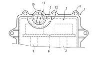
【解決手段】前記潤滑油注入管10の外周面と前記シリンダヘッドカバー7の上面との間に,前記潤滑油注入管における周囲のうち少なくとも一部を囲うように構成した補強リブ12を一体に設け,この補強リブの内部に,前記シリンダヘッドカバー内に開口する空洞部13を,前記潤滑油注入管10の周囲のうち少なくとも一部を囲うように形成する。
【選択図】 図2
Description
「内燃機関に対する潤滑油注入管を,シリンダヘッドカバーに,その上面から突出するように一体に設けて成る潤滑油注入装置において,
前記潤滑油注入管の外周面と前記シリンダヘッドカバーの上面との間には,前記潤滑油注入管における周囲のうち少なくとも一部を囲うように構成した補強リブが一体に設けられ,この補強リブの内部には,前記シリンダヘッドカバー内に開口する空洞部が,前記潤滑油注入管における周囲のうち少なくとも一部を囲うように形成されている。」
ことを特徴としている。
「前記請求項1の記載において,前記潤滑油注入管は,平面視で,シリンダヘッドカバーにおける一つのコーナ部に設けられている。」
ことを特徴としている。
2,3 カム軸
6 タイミングチエン
7 シリンダヘッドカバー
7a 上面板
10 潤滑油注入管
11 オイルフィラーキャップ
12 補強リブ
13 空洞部
Claims (2)
- 内燃機関に対する潤滑油注入管を,シリンダヘッドカバーに,その上面から突出するように一体に設けて成る潤滑油注入装置において,
前記潤滑油注入管の外周面と前記シリンダヘッドカバーの上面との間には,前記潤滑油注入管における周囲のうち少なくとも一部を囲うように構成した補強リブが一体に設けられ,この補強リブの内部には,前記シリンダヘッドカバー内に開口する空洞部が,前記潤滑油注入管における周囲のうち少なくとも一部を囲うように形成されていることを特徴とする内燃機関における潤滑油注入装置。 - 前記請求項1の記載において,前記潤滑油注入管は,平面視で,シリンダヘッドカバーにおける一つのコーナ部に設けられていることを特徴とする内燃機関における潤滑油注入装置。
Priority Applications (1)
| Application Number | Priority Date | Filing Date | Title |
|---|---|---|---|
| JP2008229453A JP2010059936A (ja) | 2008-09-08 | 2008-09-08 | 内燃機関における潤滑油注入装置 |
Applications Claiming Priority (1)
| Application Number | Priority Date | Filing Date | Title |
|---|---|---|---|
| JP2008229453A JP2010059936A (ja) | 2008-09-08 | 2008-09-08 | 内燃機関における潤滑油注入装置 |
Publications (1)
| Publication Number | Publication Date |
|---|---|
| JP2010059936A true JP2010059936A (ja) | 2010-03-18 |
Family
ID=42186991
Family Applications (1)
| Application Number | Title | Priority Date | Filing Date |
|---|---|---|---|
| JP2008229453A Pending JP2010059936A (ja) | 2008-09-08 | 2008-09-08 | 内燃機関における潤滑油注入装置 |
Country Status (1)
| Country | Link |
|---|---|
| JP (1) | JP2010059936A (ja) |
Cited By (1)
| Publication number | Priority date | Publication date | Assignee | Title |
|---|---|---|---|---|
| EP3290665A1 (en) | 2016-09-02 | 2018-03-07 | Toyota Boshoku Kabushiki Kaisha | Lubricant oil pouring structure for internal combustion engine |
Citations (3)
| Publication number | Priority date | Publication date | Assignee | Title |
|---|---|---|---|---|
| JPS61175514U (ja) * | 1985-04-19 | 1986-11-01 | ||
| JPH1150827A (ja) * | 1997-07-31 | 1999-02-23 | Toyota Motor Corp | エンジンの給油孔構造 |
| JP2005120965A (ja) * | 2003-10-20 | 2005-05-12 | Hino Motors Ltd | オイル注入口構造 |
-
2008
- 2008-09-08 JP JP2008229453A patent/JP2010059936A/ja active Pending
Patent Citations (3)
| Publication number | Priority date | Publication date | Assignee | Title |
|---|---|---|---|---|
| JPS61175514U (ja) * | 1985-04-19 | 1986-11-01 | ||
| JPH1150827A (ja) * | 1997-07-31 | 1999-02-23 | Toyota Motor Corp | エンジンの給油孔構造 |
| JP2005120965A (ja) * | 2003-10-20 | 2005-05-12 | Hino Motors Ltd | オイル注入口構造 |
Cited By (2)
| Publication number | Priority date | Publication date | Assignee | Title |
|---|---|---|---|---|
| EP3290665A1 (en) | 2016-09-02 | 2018-03-07 | Toyota Boshoku Kabushiki Kaisha | Lubricant oil pouring structure for internal combustion engine |
| JP2018035789A (ja) * | 2016-09-02 | 2018-03-08 | トヨタ紡織株式会社 | 内燃機関の潤滑油注入構造 |
Similar Documents
| Publication | Publication Date | Title |
|---|---|---|
| EP2314849A1 (en) | Method and device for mounting cam angle sensor for internal combustion engine | |
| JP2010209765A5 (ja) | ||
| US20170292471A1 (en) | Water jacket structure of cylinder head | |
| EP3290665B1 (en) | Lubricant oil pouring structure for internal combustion engine | |
| KR20130127546A (ko) | 내연 기관의 실린더 헤드 | |
| JP5695630B2 (ja) | 内燃機関のタイミングトレーンカバー構造 | |
| JP2002070642A (ja) | 多気筒エンジンのシリンダヘッド | |
| JP2015071995A (ja) | 内燃機関の排水構造 | |
| CN103362634B (zh) | 内燃机 | |
| JP2009293574A (ja) | エンジンの上部構造 | |
| JP2009215922A5 (ja) | ||
| JP3978639B2 (ja) | タイミングチェーンカバー構造 | |
| JP2011214446A (ja) | 内燃機関 | |
| JP2007146802A (ja) | 内燃機関と自動二輪車 | |
| JP2005106036A (ja) | 自動二輪車用エンジンのクランクケースカバー構造 | |
| JP2004360603A (ja) | 内燃機関の冷却装置 | |
| JP2007077893A (ja) | エンジンのロッカカバー | |
| JP2012172593A (ja) | 内燃機関 | |
| JP7343345B2 (ja) | 多気筒内燃機関のヘッドカバー | |
| EP3842629B1 (en) | Internal combustion engine, straddled vehicle, and method for manufacturing internal combustion engine | |
| JP2011157847A (ja) | 多気筒エンジン | |
| JP7356310B2 (ja) | 内燃機関 | |
| JP2014020303A (ja) | 内燃機関用ピストンおよびピストンリング | |
| JP2010209766A5 (ja) | ||
| JPH08312455A (ja) | Dohc型内燃機関におけるシリンダヘッドカバーの構造 |
Legal Events
| Date | Code | Title | Description |
|---|---|---|---|
| A621 | Written request for application examination |
Free format text: JAPANESE INTERMEDIATE CODE: A621 Effective date: 20110627 |
|
| A977 | Report on retrieval |
Free format text: JAPANESE INTERMEDIATE CODE: A971007 Effective date: 20120730 |
|
| A131 | Notification of reasons for refusal |
Free format text: JAPANESE INTERMEDIATE CODE: A131 Effective date: 20120808 |
|
| A521 | Written amendment |
Free format text: JAPANESE INTERMEDIATE CODE: A523 Effective date: 20121009 |
|
| A02 | Decision of refusal |
Free format text: JAPANESE INTERMEDIATE CODE: A02 Effective date: 20121205 |