JP2010062009A - Method for manufacturing membrane-electrode structure for fuel cell - Google Patents
Method for manufacturing membrane-electrode structure for fuel cell Download PDFInfo
- Publication number
- JP2010062009A JP2010062009A JP2008226761A JP2008226761A JP2010062009A JP 2010062009 A JP2010062009 A JP 2010062009A JP 2008226761 A JP2008226761 A JP 2008226761A JP 2008226761 A JP2008226761 A JP 2008226761A JP 2010062009 A JP2010062009 A JP 2010062009A
- Authority
- JP
- Japan
- Prior art keywords
- electrolyte membrane
- membrane
- electrode structure
- peeling
- fuel cell
- Prior art date
- Legal status (The legal status is an assumption and is not a legal conclusion. Google has not performed a legal analysis and makes no representation as to the accuracy of the status listed.)
- Pending
Links
Images

Classifications
-
- Y—GENERAL TAGGING OF NEW TECHNOLOGICAL DEVELOPMENTS; GENERAL TAGGING OF CROSS-SECTIONAL TECHNOLOGIES SPANNING OVER SEVERAL SECTIONS OF THE IPC; TECHNICAL SUBJECTS COVERED BY FORMER USPC CROSS-REFERENCE ART COLLECTIONS [XRACs] AND DIGESTS
- Y02—TECHNOLOGIES OR APPLICATIONS FOR MITIGATION OR ADAPTATION AGAINST CLIMATE CHANGE
- Y02E—REDUCTION OF GREENHOUSE GAS [GHG] EMISSIONS, RELATED TO ENERGY GENERATION, TRANSMISSION OR DISTRIBUTION
- Y02E60/00—Enabling technologies; Technologies with a potential or indirect contribution to GHG emissions mitigation
- Y02E60/30—Hydrogen technology
- Y02E60/50—Fuel cells
-
- Y—GENERAL TAGGING OF NEW TECHNOLOGICAL DEVELOPMENTS; GENERAL TAGGING OF CROSS-SECTIONAL TECHNOLOGIES SPANNING OVER SEVERAL SECTIONS OF THE IPC; TECHNICAL SUBJECTS COVERED BY FORMER USPC CROSS-REFERENCE ART COLLECTIONS [XRACs] AND DIGESTS
- Y02—TECHNOLOGIES OR APPLICATIONS FOR MITIGATION OR ADAPTATION AGAINST CLIMATE CHANGE
- Y02P—CLIMATE CHANGE MITIGATION TECHNOLOGIES IN THE PRODUCTION OR PROCESSING OF GOODS
- Y02P70/00—Climate change mitigation technologies in the production process for final industrial or consumer products
- Y02P70/50—Manufacturing or production processes characterised by the final manufactured product
Landscapes
- Fuel Cell (AREA)
Abstract
【課題】補強部材における皺の発生を抑制し、量産性に優れた燃料電池用膜−電極構造体の製造方法を提供する。
【解決手段】膜−電極構造体10は、電解質膜12を補強するための帯状の補強部材22と、補強部材22を被覆する帯状の被覆部材と、被覆部材を支持する帯状のバックアップ部材とからなる積層体を作製し(積層体作製工程)、補強部材22とバックアップ部材に共通の開口24を形成し(開口形成工程)、電解質膜12を補強部材22と接着されるように積層体と貼り合わせ(貼り合わせ工程)、作製された貼合体からバックアップ部材を剥離し(バックアップ部材剥離工程)、露出した開口24の内側の電解質膜12表面に触媒層26を形成し(触媒層形成工程)、被覆部材を剥離して(被覆部材剥離工程)、製造される。
【選択図】図1A method for producing a membrane-electrode structure for a fuel cell that suppresses generation of wrinkles in a reinforcing member and is excellent in mass productivity.
A membrane-electrode structure includes a strip-shaped reinforcing member for reinforcing an electrolyte membrane, a strip-shaped covering member for covering the reinforcing member, and a strip-shaped backup member for supporting the covering member. A laminated body is produced (laminated body producing step), a common opening 24 is formed in the reinforcing member 22 and the backup member (opening forming step), and the electrolyte membrane 12 is attached to the reinforcing member 22 so as to be bonded. Laminating (bonding step), peeling the backup member from the prepared bonded body (backup member peeling step), forming the catalyst layer 26 on the surface of the electrolyte membrane 12 inside the exposed opening 24 (catalyst layer forming step), The covering member is peeled off (covering member peeling step) to manufacture.
[Selection] Figure 1
Description
本発明は、固体高分子型燃料電池の構成要素の1つである膜−電極構造体の製造方法に関する。 The present invention relates to a method for producing a membrane-electrode structure that is one of the constituent elements of a polymer electrolyte fuel cell.
固体高分子型燃料電池は、プロトン導電性を有する固体高分子電解質膜(以下「電解質膜」という)の両面に触媒層が設けられ、この触媒層上にガス拡散層が設けられた構造を有する膜−電極構造体(MEA;Membrane Electrode Assembly)を備えている。固体高分子型燃料電池の内部抵抗を低減する観点から、電解質膜の厚さは薄いことが好ましい。しかし、電解質膜を薄くすると機械的強度が低下し、固体高分子型燃料電池の製造工程における膜−電極構造体のハンドリング性が低下する。 The polymer electrolyte fuel cell has a structure in which a catalyst layer is provided on both surfaces of a proton conductive solid polymer electrolyte membrane (hereinafter referred to as “electrolyte membrane”), and a gas diffusion layer is provided on the catalyst layer. A membrane-electrode assembly (MEA) is provided. From the viewpoint of reducing the internal resistance of the polymer electrolyte fuel cell, the electrolyte membrane is preferably thin. However, when the electrolyte membrane is thinned, the mechanical strength is lowered, and the handling property of the membrane-electrode structure in the production process of the polymer electrolyte fuel cell is lowered.
そこで、膜−電極構造体として、開口を囲むように枠部が形成された部材(以下「補強部材」という)が、電解質膜の一方の面の周縁部を被覆するように接着された構造を有するものが提案されている(例えば、特許文献1参照)。この特許文献1に開示された膜−電極構造体は、補強部材と同形状の部材(以下「被覆部材」という)と補強部材とを予め積層した状態で、補強部材を電解質膜に接着し、開口の内部に触媒層を塗工した後、被覆部材を除去することで、補強部材の内部に触媒層が形成された構造を実現している。
特許文献1に開示された構造の膜−電極構造体を作製する際には、電解質膜と補強部材とをそれぞれ、一定の力で引っ張った状態で貼り合わせする必要がある。しかし、補強部材は枠状であって、厚さも数十ミクロン程度であるために、補強部材を引っ張ると開口の四隅付近に歪みが生じやすく、その結果、電解質膜に貼り合わせされたときに開口の四隅付近に皺が発生しやすくなる。この皺は、補強部材の平滑性を低下させるため、補強部材に貼り合わせされるカーボンペーパー(ガス拡散層)に応力が掛かるようになり、カーボンペーパーが劣化しやすくなる。また、補強部材に皺が発生した状態で電解質膜に触媒ペーストを塗布して触媒層を形成すると、皺の溝となっている触媒ペーストが溜まり、この部分で、補強部材とカーボンペーパーとの接着不良が生じやすくなる。さらに電解質膜と補強部材の密着性が悪くなり補強効果が得られなくなる。 When the membrane-electrode structure having the structure disclosed in Patent Document 1 is manufactured, it is necessary to bond the electrolyte membrane and the reinforcing member together while being pulled with a certain force. However, since the reinforcing member is frame-shaped and has a thickness of about several tens of microns, when the reinforcing member is pulled, distortion is likely to occur near the four corners of the opening. It becomes easy to generate wrinkles near the four corners. Since this wrinkle reduces the smoothness of the reinforcing member, stress is applied to the carbon paper (gas diffusion layer) bonded to the reinforcing member, and the carbon paper tends to deteriorate. In addition, when the catalyst layer is formed by applying the catalyst paste to the electrolyte membrane in a state where wrinkles are generated in the reinforcing member, the catalyst paste that becomes the grooves of the wrinkles accumulates, and in this portion, the adhesion between the reinforcing member and the carbon paper Defects are likely to occur. Further, the adhesion between the electrolyte membrane and the reinforcing member is deteriorated, and the reinforcing effect cannot be obtained.
本発明はかかる事情に鑑みてなされたものであり、補強部材における皺の発生を抑制し、しかも、膜−電極構造体の量産性に優れた燃料電池用膜−電極構造体の製造方法を提供することを目的とする。 The present invention has been made in view of such circumstances, and provides a method for producing a membrane-electrode structure for a fuel cell that suppresses generation of wrinkles in a reinforcing member and is excellent in mass productivity of the membrane-electrode structure. The purpose is to do.
本発明に係る燃料電池用膜−電極構造体の製造方法は、固体高分子型燃料電池に用いられる膜−電極構造体の製造方法であって、固体高分子電解質膜を補強するための帯状の第1の部材と、前記第1の部材を被覆するための帯状の第2の部材と、前記第2の部材を支持するための帯状の第3の部材とをこの順序で、後に剥離可能となるように積層接着して積層体を作製する積層体作製工程と、前記積層体作製工程によって得られた積層体の前記第1の部材と前記第2の部材に共通の開口を設ける開口形成工程と、帯状の固体高分子電解質膜を、前記第1部材と接着されるように前記積層体に貼り合わせて、貼合体を作製する貼り合わせ工程と、前記貼り合わせ工程によって得られた貼合体から前記第3の部材を剥離除去する第1の剥離工程と、前記第1の剥離工程後の貼合体の表面に現れた前記開口の内側に触媒層を形成する触媒層形成工程と、前記触媒層形成工程後の貼合体から前記第2の部材を剥離する第2の剥離工程と、を有することを特徴とする。 A method for producing a membrane-electrode structure for a fuel cell according to the present invention is a method for producing a membrane-electrode structure used for a polymer electrolyte fuel cell, and is a belt-like structure for reinforcing a polymer electrolyte membrane. The first member, the belt-like second member for covering the first member, and the belt-like third member for supporting the second member can be peeled later in this order. A laminated body production step of producing a laminated body by laminating and bonding, and an opening forming step of providing a common opening in the first member and the second member of the laminated body obtained by the laminated body production step From the bonding process obtained by the bonding process of bonding the band-shaped solid polymer electrolyte membrane to the laminate so as to be bonded to the first member, and preparing the bonded body, and the bonding process A first peeling step for peeling and removing the third member; A catalyst layer forming step of forming a catalyst layer inside the opening that appears on the surface of the bonded body after the first peeling step, and a second step of peeling the second member from the bonded body after the catalyst layer forming step. And 2 peeling processes.
このような構成によれば、第1の部材と第2の部材に開口を形成したときにはこれらは第3の部材に支持されているため、積層体において第1の部材における皺の発生が抑制される。そして、このような積層体を用いることで、固体高分子電解質膜に接着された第1の部材における皺の発生を抑制することができる。また、膜−電極構造体の全製造工程を通じて、取り扱われる各種の部材(積層体、貼合体を含む)の自立性が高く、ハンドリングが容易であるため、生産性に優れている。さらに、帯状の部材等を用いることで、各工程を連続的に行うことができるため、量産性にも優れている。 According to such a configuration, when the openings are formed in the first member and the second member, these are supported by the third member, so that generation of wrinkles in the first member is suppressed in the stacked body. The And by using such a laminated body, generation | occurrence | production of the flaw in the 1st member adhere | attached on the solid polymer electrolyte membrane can be suppressed. Moreover, since all the members (including a laminated body and a bonded body) to be handled are high and easy to handle throughout the entire manufacturing process of the membrane-electrode structure, it is excellent in productivity. Furthermore, since each process can be performed continuously by using a strip-shaped member or the like, it is excellent in mass productivity.
本発明に係る燃料電池用膜−電極構造体の製造方法では、前記積層体作製工程において、前記第1の部材と前記第2の部材との間の接着強度を、前記第2の部材と前記第3の部材との間の接着強度より大きくすることが好ましい。 In the method for producing a membrane-electrode structure for a fuel cell according to the present invention, in the laminate manufacturing step, the adhesive strength between the first member and the second member is set to the second member and the second member. It is preferable to make it larger than the adhesive strength between the third member.
このような構成によれば、第1の剥離工程において、第3の部材を剥離する際に、第2の部材が同時に剥離することを抑制することができる。 According to such a structure, when peeling a 3rd member in a 1st peeling process, it can suppress that a 2nd member peels simultaneously.
本発明に係る燃料電池用膜−電極構造体の製造方法では、前記貼り合わせ工程において、前記固体高分子電解質膜と前記第1の部材との貼り合わせを、熱硬化性接着剤を用いて熱プレスにより行うことが好ましい。また、このように熱プレスを用いる場合には、前記第2の部材と前記第3の部材の熱膨張係数は、同じであることが好ましい。 In the method for producing a membrane-electrode structure for a fuel cell according to the present invention, in the bonding step, the solid polymer electrolyte membrane and the first member are bonded to each other with a thermosetting adhesive. It is preferable to carry out by pressing. Moreover, when using a hot press in this way, it is preferable that the thermal expansion coefficients of the second member and the third member are the same.
このような構成によれば、熱硬化性接着剤を用いて固体高分子電解質膜と第1の部材とをより強固かつ緊密に接着することができる。なお、熱プレスとして熱ロールプレスを用いることで、固体高分子電解質膜と積層体とを長さ方向で連続して接着を行うことができるため、生産性が高められる。そして、第2の部材と第3の部材の熱膨張係数が同じであると、熱プレスを行ったときに、第2の部材に皺が入りにくくなる。 According to such a configuration, the solid polymer electrolyte membrane and the first member can be bonded more firmly and tightly using the thermosetting adhesive. In addition, since a solid polymer electrolyte membrane and a laminated body can be adhere | attached continuously in a length direction by using a hot roll press as a hot press, productivity is improved. If the second member and the third member have the same thermal expansion coefficient, it is difficult for wrinkles to enter the second member when hot pressing is performed.
本発明に係る燃料電池用膜−電極構造体の製造方法においては、前記第1の部材の幅が、前記固体高分子電解質膜と第2の部材の両方の幅よりも狭いことが好ましい。 In the method for producing a membrane-electrode structure for a fuel cell according to the present invention, the width of the first member is preferably narrower than the widths of both the solid polymer electrolyte membrane and the second member.
このような構成によれば、第2の部材が固体高分子電解質膜の表面に直接固定されるため、第1の部材の位置ずれを抑制することができる。 According to such a configuration, since the second member is directly fixed to the surface of the solid polymer electrolyte membrane, it is possible to suppress displacement of the first member.
本発明に係る燃料電池用膜−電極構造体の製造方法においては、前記固体高分子電解質膜は帯状の基材の一面に形成されており、前記貼り合わせ工程以降の工程は、前記固体高分子電解質膜が前記基材表面に形成された状態で行われ、前記第2の部材の幅が、前記第1の部材の幅と前記固体高分子電解質膜の幅のいずれの幅よりも広いことが好ましい。 In the method for producing a membrane-electrode structure for a fuel cell according to the present invention, the solid polymer electrolyte membrane is formed on one surface of a strip-shaped substrate, and the steps after the bonding step are the solid polymer. It is performed in a state where the electrolyte membrane is formed on the surface of the base material, and the width of the second member is wider than any of the width of the first member and the width of the solid polymer electrolyte membrane. preferable.
このような構成によれば、第2の部材を基材に直接接着することができ、これによって、第1の部材の位置ずれを抑制することができる。なお、第2の部材と基材との間の接着は、第2の部材と基材とが剥離可能な接着力を有する粘着剤を用いて行われる。 According to such a structure, the 2nd member can be directly adhere | attached on a base material, and, thereby, the position shift of a 1st member can be suppressed. In addition, adhesion | attachment between a 2nd member and a base material is performed using the adhesive which has the adhesive force which can peel a 2nd member and a base material.
本発明に係る燃料電池用膜−電極構造体の製造方法によれば、固体高分子電解質膜にこれを補強するための第1の部材を接着する際に、皺の発生が抑えられた第1の部材を備えた積層体を用いることで、固体高分子電解質膜に第1の部材が接着されたときの第1の部材における皺の発生が抑制される。こうして第1の部材の表面の平滑性が高められるため、第1の部材に貼り付けられるカーボンペーパー等のガス拡散層用部材に不均一な応力が掛かり難くなって、カーボンペーパー等を長寿命化することができる。また、第1の部材の表面に触媒ペーストが溜まり難くなるために、カーボンペーパー等と良好な接着性を確保することができる。 According to the method for producing a membrane-electrode structure for a fuel cell according to the present invention, when the first member for reinforcing the solid polymer electrolyte membrane is bonded, the generation of wrinkles is suppressed. By using the laminated body provided with the member, the generation of wrinkles in the first member when the first member is bonded to the solid polymer electrolyte membrane is suppressed. Since the smoothness of the surface of the first member is improved in this way, it becomes difficult for non-uniform stress to be applied to the member for the gas diffusion layer such as carbon paper attached to the first member, thereby extending the life of the carbon paper. can do. In addition, since the catalyst paste hardly accumulates on the surface of the first member, it is possible to ensure good adhesion with carbon paper or the like.
本発明に係る燃料電池用膜−電極構造体の製造方法は、全製造工程を通じて、取り扱われる各種の部材(積層体、貼合体を含む)の自立性が高く、ハンドリングが容易であるため、生産性に優れている。さらに、帯状の部材等を用いることで、連続的な処理を容易に行うことができるために、量産性にも優れている。 The method for producing a membrane-electrode structure for a fuel cell according to the present invention has high self-sustainability of various members (including laminates and bonded bodies) handled throughout the entire production process, and is easy to handle. Excellent in properties. Furthermore, since a continuous process can be easily performed by using a strip-shaped member or the like, it is excellent in mass productivity.
以下、本発明の実施の形態について図面を参照して詳細に説明する。
<膜−電極構造体の構造>
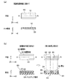
図1に固体高分子型燃料電池の構成要素である膜−電極構造体の概略断面図を示す。図1(a),(b)にそれぞれ示される2つの膜−電極構造体10は共に、プロトン導電性を有する固体高分子電解質膜(以下「電解質膜」という)12を挟んで、一方の主面にアノード側ガス拡散電極14が設けられ、他方の主面にカソード側ガス拡散電極16が設けられた構造を有している。なお、図1(a),(b)に示されるように三次元直交座標(X−Y−Z)を定め、電解質膜12の長さ方向をX方向とし、電解質膜12の幅方向をY方向とし、電解質膜12の厚さ方向をX方向とする。
Hereinafter, embodiments of the present invention will be described in detail with reference to the drawings.
<Structure of membrane-electrode structure>
FIG. 1 shows a schematic cross-sectional view of a membrane-electrode structure which is a constituent element of a polymer electrolyte fuel cell. The two membrane-
アノード側ガス拡散電極14は、矩形の開口24を囲む枠状の形状(図1(a),(b)ではY方向側の部分しか明示されていない)を有し、電解質膜12の主面に接着された補強部材22と、補強部材22の開口24内において電解質膜12表面に形成された触媒層26と、補強部材22と触媒層26とを覆うガス拡散層28とを備えている。カソード側ガス拡散電極16は、アノード側ガス拡散電極14と実質的に同じ構造を有している。1つの膜−電極構造体10は、1つの開口24を有する矩形形状を有している。
The anode-side
なお、図1(a)に示される膜−電極構造体10では、電解質膜12の幅が補強部材22の幅よりも広くなっており、図1(b)に示される膜−電極構造体10では、電解質膜12の幅と補強部材22の幅とが同じになっている。後記するように、図1(a)に示される膜−電極構造体10の電解質膜12の幅方向端を切断することにより、図1(b)に示される膜−電極構造体10を得ることができる。また、図1(b)に示される膜−電極構造体10は、これを製造するために用いる電解質膜12の幅と補強部材22の幅とを同じとすることによって、電解質膜12の幅方向端を切断することなく、製造することもできる。
In the membrane-
例えば、触媒層26は白金を主成分とする材料で構成され、ガス拡散層28には多孔質カーボンクロスや多孔質カーボンペーパーが用いられ、電解質膜12にはフッ素系樹脂の一種であるパーフルオロカーボンスルホン酸ポリマー等が用いられる。補強部材22としては、ポリイミド樹脂(PI),ポリテトラフロオロエチレン(PTFE),ポリエーテルエーテルケトン(PEEK),ポリフェニレンサルファイド(PPS)等が好適に用いられ、その厚さは、5〜50μmとすることができる。電解質膜12と補強部材22とは、エポキシ樹脂等の熱硬化性樹脂接着剤(接着層を図示せず)によって接着されており、ガス拡散層28も接着剤を用いて補強部材22に接着されている。
For example, the
<膜−電極構造体の製造方法>
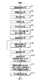
図2に膜−電極構造体の製造工程を表したフローチャートを示す。膜−電極構造体10の製造工程は、概略、電解質膜準備工程S1、積層体作製工程S2、開口形成工程S3、仮固定工程S4、貼り合わせ工程S5、バックアップ部材剥離工程(第1の剥離工程)S6、触媒層形成工程S7、被覆部材剥離工程(第2の剥離工程)S8、基材剥離工程S9、裏面処理工程S10(電解質膜12の裏面に対して仮固定工程S4から触媒層形成工程S7までを繰り返し行う工程)、被覆部材剥離工程(S8を飛ばした場合には電解質膜12の両面の被覆部材を剥離)S11、ガス拡散層形成工程S12、の各工程からなる。
<Method for Manufacturing Membrane-Electrode Structure>
FIG. 2 is a flowchart showing the manufacturing process of the membrane-electrode structure. The manufacturing process of the membrane-
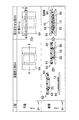
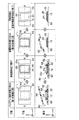
図3(a)に電解質膜準備工程で準備する電解質膜の形態を表した平面図と断面図(平面図に示すA−A位置での断面図)を示し、図3(b)に積層体作製工程と開口形成工程における処理の態様を模式的に表した平面図と断面図(平面図に示すA−A位置での断面図)を示す。また、図4に仮固定工程と貼り合わせ工程における処理の態様を模式的に表した平面図と断面図(平面図に示すB−B位置での断面図)を示し、図5にバックアップ部材剥離工程から被覆部材剥離工程までの処理の態様を模式的に表した平面図と断面図(平面図に示すB−B位置での断面図)を示す。これらの図3〜5に示す三次元直交座標(X−Y−Z)は、図1(a),(b)に示した三次元直交座標(X−Y−Z)と対応している。以下、これらの図面を参照しながら各工程について説明する。 FIG. 3A shows a plan view and a cross-sectional view (cross-sectional view at the position AA shown in the plan view) showing the form of the electrolyte membrane prepared in the electrolyte membrane preparation step, and FIG. 3B shows a laminate. The top view and sectional view (sectional view in the AA position shown to a top view) which represented the aspect of the process in a preparation process and an opening formation process typically are shown. Further, FIG. 4 shows a plan view and a cross-sectional view (cross-sectional view at the BB position shown in the plan view) schematically showing the process in the temporary fixing step and the bonding step, and FIG. 5 shows the backup member peeling. The top view and sectional drawing (cross-sectional view in the BB position shown to a top view) which represented the aspect of the process from a process to a covering member peeling process typically are shown. These three-dimensional orthogonal coordinates (XYZ) shown in FIGS. 3 to 5 correspond to the three-dimensional orthogonal coordinates (XYZ) shown in FIGS. Hereinafter, each process will be described with reference to these drawings.
[電解質膜準備工程S1]
膜−電極構造体10を製造するために電解質膜12を準備する。本製造方法では、図3(a)に示されるように、電解質膜12として、帯状の電解質膜支持基材(以下「基材」という)50の一面に支持された状態にあるものが好適に用いられる。電解質膜12を基材50で支持しておくことにより、膜−電極構造体10の製造工程における電解質膜12のハンドリング性が向上する。基材50としては、例えば、電解質膜12との密着性と剥離性のバランスがよく、熱的にも安定なPETフィルム等が好適に用いられ、その厚さは、ハンドリング性等を考慮して、約数十ミクロン程度とすることが好ましい。
[Electrolyte membrane preparation step S1]
In order to manufacture the membrane-
電解質膜12の幅は基材50の幅よりも狭いことが好ましく、例えば、基材50の幅方向端から一定距離の位置に電解質膜12の幅方向端が位置するようにする。これにより、後に行われる仮固定工程S4において、電解質膜12と補強部材22との位置合わせを簡単に行うことができる。このような基材50に支持された電解質膜12は、ロール状に巻回された状態で準備することができ、仮固定工程S4以降に用いられる。
The width of the
[積層体作製工程S2]
図3(b)に示すように、積層体作製工程S2は、電解質膜12を補強するための帯状の補強部材(第1の部材)22と、補強部材22を被覆するための帯状の被覆部材(第2の部材)62と、被覆部材62を支持するための帯状のバックアップ部材(第3の部材)64とをこの順序で長さ方向を合わせ、後に剥離可能となるように積層接着して、積層体60を作製する工程である。ここで、被覆部材62は、積層体60においては中間層であるが、後に行われるバックアップ部材剥離工程S6後に補強部材22を被覆した状態になる部材であることから、これを「被覆部材」ということとする。
[Laminate Fabrication Step S2]
As shown in FIG. 3B, the laminate manufacturing step S <b> 2 includes a strip-shaped reinforcing member (first member) 22 for reinforcing the
補強部材22には、前記した所定厚さのポリイミド樹脂等が用いられる。被覆部材62とバックアップ部材64にはPET樹脂等が好適に用いられ、その厚さは10〜80μmとすることができる。
The reinforcing
補強部材22と被覆部材62との接着と、被覆部材62とバックアップ部材64との接着にはそれぞれ、市販の粘着剤が用いられる。この粘着剤としては、後に行われる貼り合わせ工程S5における加熱処理によって変質しない性質を有しているものが、工程管理上、好適である。積層体60において、補強部材22と被覆部材62との間の接着強度は、被覆部材62とバックアップ部材64との間の接着強度よりも大きいことが好ましい。これは、後に行われるバックアップ部材剥離工程(第1の剥離工程)S6において、バックアップ部材64を剥離する際に、被覆部材62がバックアップ部材64と一緒に剥離してしまうのを防止するためである。使用する粘着剤の種類(粘着成分の化学種や濃度等)や粘着層の厚さを制御することによって、これらの接着強度に差を設けることができる。
Commercially available adhesives are used for adhesion between the reinforcing
補強部材22、被覆部材62及びバックアップ部材64を積層接着する際には、通常、各接着面に空気が入らないように、各部材に一定の張力を加えることが好ましい。図3(b)に示されるように、積層体作製工程S2の段階では、補強部材22には開口24は形成されていない。また、被覆部材62にも後工程の開口形成工程S3で開口68が形成されるが、積層体作製工程S2の段階では、被覆部材62にも開口68は形成されていない。このように、開口24が形成されていない補強部材22と、開口68が形成されていない被覆部材62を用いて積層体60を作製することにより、補強部材22と被覆部材62に局所的に皺等が発生することが抑制され、その平坦性を高めることができる。
When the reinforcing
こうして、補強部材22の平坦性が確保されると、後に行われる触媒層形成工程S7において、補強部材22と被覆部材62との間に触媒材料が侵入することを抑制することができるため、後に、補強部材22にガス拡散層28としてのカーボンペーパー等を貼り付けたときに接着不良が発生することを回避することができる。また、作製した膜−電極構造体10を用いてセルを組む際に、補強部材22に貼り付けられたガス拡散層28としてのカーボンペーパー等に応力が掛かり難くなり、カーボンペーパー等の破壊を抑制することができる。
Thus, when the flatness of the reinforcing
積層体60は、後に行われる仮固定工程S4と貼り合わせ工程S5によって、基材50に支持された電解質膜12と接着され、貼合体80(図4,5参照)が作製される。この貼合体80の作製を容易かつ正確に行うことができるように、電解質膜12と基材50の幅を踏まえて、補強部材22、被覆部材62及びバックアップ部材64の各幅を設定することが好ましい。その設定条件は、後記する仮固定工程S4についての説明において述べる。
The
[開口形成工程S3]
図3(b)に示されるように、開口形成工程S3は、積層体作製工程S2によって得られた積層体60の補強部材22と被覆部材62に共通の開口24,68をそれぞれ設ける工程である。例えば、開口24,68の外周形状を有する刃を、補強部材22側から被覆部材62とバックアップ部材64との接着面までの深さで挿入し、補強部材22と被覆部材62に切れ目を設けた後、開口24,68の領域部分を剥離することにより、開口24,68を形成することができる。開口24,68が形成された積層体60は、ロール状に巻回された状態で保管してもよい。また、開口24,68が形成された後に、速やかに、次の仮固定工程S4に供給されるようにしてもよい。ここでは、積層体作製工程S2と開口形成工程S3によって、電解質膜12の表面と裏面のそれぞれに貼り合わせることができるだけの長さの積層体60が作製されたものとする。
[Opening Step S3]
As shown in FIG. 3B, the opening forming step S3 is a step of providing
[仮固定工程S4]
仮固定工程S4は、図4に示されるように、電解質膜12と補強部材22とを接着するために、基材50に支持された電解質膜12と積層体60とを位置合わせして、これらを密着させる工程である。仮固定工程S4の前に、補強部材22の表面に熱硬化性樹脂接着剤を所定の厚さ(例えば、数ミクロン)で塗布しておく。但し、仮固定工程S4では、この熱硬化性樹脂接着剤を硬化させない。なお、図4の平面図には、帯状の積層体60の長さ方向(X方向)の一部のみが描かれている(図5についても同様)。
[Temporary fixing step S4]
In the temporary fixing step S4, as shown in FIG. 4, in order to bond the
本実施形態では、図4に示されるように、電解質膜12の幅を基材50の幅よりも狭くしていることを踏まえて、積層体作製工程S2において、基材50の幅とバックアップ部材64の幅とを同じとし、被覆部材62の幅をバックアップ部材64の幅と同じとし、補強部材22の幅を電解質膜12の幅よりも狭くしている。その結果、被覆部材62の幅は補強部材22幅と電解質膜12の幅のいずれの幅よりも広くなっている。このとき、被覆部材62の露出面には、積層体作製工程S2で用いた粘着剤が塗布された状態で残っていることが好ましい。
In the present embodiment, as shown in FIG. 4, based on the fact that the width of the
基材50の幅とバックアップ部材64の幅とを同じとすることにより、基材50と積層体60との位置合わせが容易となる。被覆部材62の幅をバックアップ部材64の幅と同じとすることにより、積層体60における幅方向の厚さの変化が小さくなるため、後工程の貼り合わせ工程S5において積層体60と基材50に支持された電解質膜12とを貼り合わせた際に、貼合体80(図4,5参照)において生じる幅方向での歪みを小さく抑えることができる。補強部材22の幅を電解質膜12の幅よりも狭くすることにより、補強部材22を直接かつ確実に電解質膜12と密着させることができる。
By making the width of the
被覆部材62の幅が補強部材22の幅と電解質膜12の幅のいずれの幅よりも広くなっていることにより、補強部材22の全面を被覆部材62によって支持することができ、被覆部材62の露出面に粘着剤が塗布されていることにより、被覆部材62が基材50と接着されて被覆部材62の位置が安定する。これらの効果によって、補強部材22の位置を安定して保持することができ、補強部材22の位置ずれを抑制することができる。
Since the width of the covering
[貼り合わせ工程S5]
貼り合わせ工程S5は、電解質膜12と補強部材22とを強固に接着する工程である。貼り合わせ工程S5は、図4に示されるように、例えば、仮固定工程S4で基材50に支持された電解質膜12と積層体60とを仮固定したものを熱ロール70の間に通して、一定の圧力をかけながら加熱することによって行われる。これによって、電解質膜12と補強部材22との間の熱硬化性樹脂接着剤が一定の厚さで硬化し、電解質膜12と補強部材22とが強固に接着されると共に、基材50に支持された電解質膜12と積層体60とが貼り合わせされた貼合体80が作製される。
[Lamination process S5]
The bonding step S5 is a step of firmly bonding the
貼り合わせ工程S5において、被覆部材62に皺等の変形が生じないように、被覆部材62とバックアップ部材64には、同じ熱膨張率の材料を用いることが好ましい。熱ロール70の設定温度や回転速度(電解質膜12を支持した基材50と積層体60とを通過させる速さ)は、電解質膜12と補強部材22との間に介在している不図示の熱硬化性樹脂接着剤の熱硬化特性等を考慮して、適宜、定められる。
In the bonding step S5, it is preferable to use materials having the same thermal expansion coefficient for the covering
なお、基材50(電解質膜12)と積層体60とが帯状であるため、熱ロール70を用いる方法は、電解質膜12と補強部材22との接着を連続的に行うことができる点で、生産性に優れている。
In addition, since the base material 50 (electrolyte film | membrane 12) and the
[バックアップ部材剥離工程(第1の剥離工程)S6]
図5に示されるように、バックアップ部材剥離工程(第1の剥離工程)S6は、貼り合わせ工程S5で作製した貼合体80からバックアップ部材64を剥離して、開口24,68内の電解質膜12の表面を露出させる工程である。このバックアップ部材64の剥離は、室温で行うことができる。前記したように、補強部材22と被覆部材62との間の接着強度を、被覆部材62とバックアップ部材64との間の接着強度よりも大きくしておくと、補強部材22を剥離させることなく、バックアップ部材64のみを剥離することが容易となる。
[Backup member peeling step (first peeling step) S6]
As shown in FIG. 5, in the backup member peeling step (first peeling step) S6, the
[触媒層形成工程S7]
触媒層形成工程S7は、バックアップ部材剥離工程S6によって開口24,68内に露出した電解質膜12に対して、触媒層26となるペースト等の材料(以下「触媒材料」という)を塗布し、触媒層26を形成する工程である。このとき、補強部材22の全面が被覆部材62によって覆われているために、被服材料62の開口68の近傍の表面に余分な触媒塗布部26aが形成されることはあっても、補強部材22の表面に触媒材料が付着することがない。これにより、後に行われるガス拡散層形成工程S12において、補強部材22にガス拡散層28としてのカーボンペーパー等を貼り付けたときに接着不良が発生すること回避することができる。
[Catalyst layer forming step S7]
In the catalyst layer forming step S7, a material such as a paste (hereinafter referred to as “catalyst material”) that becomes the
本製造方法によれば、触媒層形成工程S7によって形成される触媒層26の外縁は開口24の内縁と一致するため、従来の電解質膜に触媒層を先に設け、その触媒層を囲むように補強部材を設ける方法において必要とされる補強部材の精密な位置決めを必要としない。これにより、歩留まりが高くなり、生産性が向上する。
According to this manufacturing method, since the outer edge of the
[被覆部材剥離工程(第2の剥離工程)S8]
被覆部材剥離工程S8は、図5に示されるように、触媒層26が形成された後に、被覆部材62を基材50等から剥離する工程である。被覆部材剥離工程S8の終了によって、電解質膜の表面の触媒層26の形成までの工程が終了する。なお、貼合体80から剥離した被覆部材62に付着した余分な触媒塗布部26aの触媒材料は、化学的手段(例えば、溶解等)や物理的手段(例えば、剥離等)によって、簡単に高い効率で回収することができるため、触媒材料の再生利用効率を高めることができる。
[Coating member peeling step (second peeling step) S8]
The covering member peeling step S8 is a step of peeling the covering
ところで、図1(a),(b)を参照して説明したように、膜−電極構造体10では、電解質膜12の両面に補強部材22が設けられ、その開口24内に触媒層26が形成されている。そのためには、被覆部材剥離工程S8を行った後に、基材50を電解質膜12から剥離する基材剥離工程S9を経て、裏面処理工程S10(電解質膜12の裏面に対して仮固定工程S4から触媒層形成工程S7までを繰り返し行う工程)を実行してもよいし、被覆部材剥離工程S8を飛ばして、基材剥離工程S9と裏面処理工程S10とを逐次行ってもよい。なお、裏面処理工程を仮固定工程S4から触媒層形成工程S7までとしたのは、裏面処理工程S10に用いる積層体60が既に準備されていることを前提としている。
By the way, as described with reference to FIGS. 1A and 1B, in the membrane-
被覆部材剥離工程S8を行った後に基材剥離工程S9を経てこの裏面処理工程S10に進んだ場合でも、電解質膜12の裏面に触媒層26を形成した際の電解質膜12の膨潤による寸法変化は、電解質膜12の表面に先に設けられた補強部材22によって抑制され、補助的には触媒層26によっても抑制されうる。また、被覆部材剥離工程S8を飛ばして基材剥離工程S9を経てこの裏面処理工程S10に進んだ場合には、電解質膜12の裏面に触媒層26を形成した際の電解質膜12の膨潤による寸法変化が、電解質膜12の表面に先に設けられた触媒層26のみならず、被覆部材62によっても抑制され、また、被覆部材62が貼り付けられたままの状態にあることで、電解質膜12のハンドリング性が向上する。
Even when the coating member peeling step S8 is performed and then the substrate peeling step S9 is performed and then the back surface processing step S10 is performed, the dimensional change due to the swelling of the
[基材剥離工程S9]
基材剥離工程S9は、基材50を電解質膜12から剥離する工程であり、これにより基材50と接触していた電解質膜12の裏面が露出し、積層体60との貼り合わせが可能になる。
[Substrate peeling step S9]
The base material peeling step S9 is a step of peeling the
[裏面処理工程S10]
裏面処理工程S10は、基材剥離工程S9によって露出した電解質膜12の裏面に、積層体60を位置合わせして仮固定し(仮固定工程S4)、積層体60を貼り合わせ(貼り合わせ工程S5)、作製された貼合体80からバックアップ部材64を剥離し(バックアップ部材剥離工程S6)、触媒層26を形成する(触媒層形成工程S7)一連の工程である。
[Back treatment step S10]
In the back surface processing step S10, the
[被覆部材剥離工程S11]
電解質膜12の裏面側に触媒層26が形成された後には、先に被覆部材剥離工程S8が実行されている場合には、電解質膜12の裏面側に取り付けられている被覆部材62を剥離し、一方、先に被覆部材剥離工程S8を飛ばしている場合には、電解質膜12の両面(表面側と裏面側)にそれぞれ取り付けられている被覆部材62を剥離する。
[Coating member peeling step S11]
After the
[ガス拡散層形成工程S12]
被覆部材剥離工程S11が終了した後には、補強部材22の表面が露出している。そこで、補強部材22の表面に接着剤等によりガス拡散層28となるカーボンペーパー等を貼り付けることにより、ガス拡散層28を形成し、その後、隣接する開口24(適宜、図2(b)参照)の中間位置でY方向と平行に切断することにより、図1(a)に示される膜−電極構造体10が得られる。なお、この切断処理は、被覆部材剥離工程S11の終了後、ガス拡散層形成工程S12の前に行ってもよい。その後、個々の膜−電極構造体10(図1(a)に示されるもの)における電解質膜12の幅方向端部を補強部材22の幅方向端とそろうように切断することで、図1(b)に示される膜−電極構造体10が製造される。この電解質膜12の端部の切断は、被覆部材剥離工程S11の終了直後に前記した切断処理を行った場合には、その切断処理の直後、かつ、ガス拡散層28の形成前に行なってもよい。
[Gas diffusion layer forming step S12]
After the covering member peeling step S11 is completed, the surface of the reinforcing
このような膜−電極構造体10の製造方法によれば、全製造工程を通じて、取り扱われる各種の部材(積層体60、貼合体80を含む)の自立性が高く、ハンドリングが容易であるため、生産性に優れている。さらに、帯状の部材等を用いることで、各工程を一連の流れ作業として連続して行うことができるために、量産性にも優れている。
According to the manufacturing method of such a membrane-
以上、本発明の実施の形態について説明したが、本発明は前記した形態に限定されるものではない。例えば、図1(a),(b)に示される膜−電極構造体はガス拡散層28を有していなくてもよい。図2に示される膜−電極構造体10の製造工程では、貼合体80を作製した後にバックアップ部材64を剥離し、触媒層26を形成するとしたが、これに限られず、貼合体80を作製した後に基材50を剥離し、これにより露出した電解質膜12の裏面に積層体60を貼り付けることによって、2つの積層体60で電解質膜12が挟持された構造を有する貼合体を作製し、その後、各積層体60のバックアップ部材64を剥離して触媒層26を形成するようにしてもよい。
As mentioned above, although embodiment of this invention was described, this invention is not limited to an above described form. For example, the membrane-electrode structure shown in FIGS. 1A and 1B may not have the
また、膜−電極構造体10の製造工程として、基材50に支持された電解質膜12を用いた形態について説明したが、電解質膜12を自立膜として取り扱える場合には、積層体60に電解質膜12を貼り合わせてもよい。この場合、電解質膜12の両面に積層体60を位置決めして貼り合わせることにより、熱ロール70が直接に電解質膜12に接触することを防止することができる。こうして、例えば、熱ロール70の表面に凹凸等の欠陥があったときにも、その欠陥が電解質膜12に転写されるのを防止することができる。
Moreover, although the form using the
10 膜−電極構造体
12 電解質膜(固体高分子電解質膜)
14 アノード側ガス拡散電極
16 カソード側ガス拡散電極
22 補強部材(第1の部材)
24 開口
26 触媒層
26a (余分な)触媒塗布部
28 ガス拡散層
50 基材(電解質膜支持基材)
60 積層体
62 被覆部材(第2の部材)
64 バックアップ部材(第3の部材)
68 開口
70 熱ロール
80 貼合体
10 Membrane-
14 Anode-side
24
60
64 Backup member (third member)
68
Claims (6)
固体高分子電解質膜を補強するための帯状の第1の部材と、前記第1の部材を被覆するための帯状の第2の部材と、前記第2の部材を支持するための帯状の第3の部材とをこの順序で、後に剥離可能となるように積層接着して積層体を作製する積層体作製工程と、
前記積層体作製工程によって得られた積層体の前記第1の部材と前記第2の部材に共通の開口を設ける開口形成工程と、
帯状の固体高分子電解質膜を、前記第1部材と接着されるように前記積層体に貼り合わせて貼合体を作製する貼り合わせ工程と、
前記貼り合わせ工程によって得られた貼合体から前記第3の部材を剥離除去する第1の剥離工程と、
前記第1の剥離工程後の貼合体の表面に現れた前記開口の内側に触媒層を形成する触媒層形成工程と、
前記触媒層形成工程後の貼合体から前記第2の部材を剥離する第2の剥離工程と、を有することを特徴とする燃料電池用膜−電極構造体の製造方法。 A method for producing a membrane-electrode structure for a fuel cell used in a polymer electrolyte fuel cell,
A strip-shaped first member for reinforcing the solid polymer electrolyte membrane, a strip-shaped second member for covering the first member, and a strip-shaped third member for supporting the second member In this order, a laminated body production step of producing a laminated body by laminating and bonding so that the members can be peeled later in this order,
An opening forming step of providing a common opening in the first member and the second member of the laminate obtained by the laminate production step;
A laminating step of laminating a band-shaped solid polymer electrolyte membrane to the laminate so as to be bonded to the first member,
A first peeling step of peeling and removing the third member from the bonded body obtained by the bonding step;
A catalyst layer forming step of forming a catalyst layer inside the opening that appeared on the surface of the bonded body after the first peeling step;
And a second peeling step of peeling the second member from the bonded body after the catalyst layer forming step. A method for producing a membrane-electrode structure for a fuel cell.
前記第1の部材と前記第2の部材との間の接着強度を、前記第2の部材と前記第3の部材との間の接着強度より大きくすることを特徴とする請求項1に記載の燃料電池用膜−電極構造体の製造方法。 In the laminate manufacturing process,
2. The adhesive strength between the first member and the second member is larger than the adhesive strength between the second member and the third member. A method for producing a membrane-electrode structure for a fuel cell.
前記固体高分子電解質膜と前記第1の部材との接着を、熱硬化性接着剤を用いて熱プレスにより行うことを特徴とする請求項1又は請求項2に記載の燃料電池用膜−電極構造体の製造方法。 In the bonding step,
The fuel cell membrane-electrode according to claim 1 or 2, wherein the solid polymer electrolyte membrane and the first member are bonded by hot pressing using a thermosetting adhesive. Manufacturing method of structure.
前記第2の部材の幅が、前記第1の部材の幅と前記固体高分子電解質膜の幅のいずれの幅よりも広いことを特徴とする請求項1から請求項5のいずれか1項に記載の燃料電池用膜−電極構造体の製造方法。 The solid polymer electrolyte membrane is formed on one surface of a strip-shaped substrate, and the steps after the bonding step are performed in a state where the solid polymer electrolyte membrane is formed on the substrate surface,
The width of the second member is wider than any of the width of the first member and the width of the solid polymer electrolyte membrane, according to any one of claims 1 to 5. The manufacturing method of the membrane-electrode structure for fuel cells of description.
Priority Applications (1)
| Application Number | Priority Date | Filing Date | Title |
|---|---|---|---|
| JP2008226761A JP2010062009A (en) | 2008-09-04 | 2008-09-04 | Method for manufacturing membrane-electrode structure for fuel cell |
Applications Claiming Priority (1)
| Application Number | Priority Date | Filing Date | Title |
|---|---|---|---|
| JP2008226761A JP2010062009A (en) | 2008-09-04 | 2008-09-04 | Method for manufacturing membrane-electrode structure for fuel cell |
Publications (1)
| Publication Number | Publication Date |
|---|---|
| JP2010062009A true JP2010062009A (en) | 2010-03-18 |
Family
ID=42188586
Family Applications (1)
| Application Number | Title | Priority Date | Filing Date |
|---|---|---|---|
| JP2008226761A Pending JP2010062009A (en) | 2008-09-04 | 2008-09-04 | Method for manufacturing membrane-electrode structure for fuel cell |
Country Status (1)
| Country | Link |
|---|---|
| JP (1) | JP2010062009A (en) |
Cited By (6)
| Publication number | Priority date | Publication date | Assignee | Title |
|---|---|---|---|---|
| JP2011003289A (en) * | 2009-06-16 | 2011-01-06 | Teijin Ltd | Biaxially drawn film for solid polymer electrolyte membrane reinforcement |
| JP2012069420A (en) * | 2010-09-24 | 2012-04-05 | Dainippon Printing Co Ltd | Solid oxide fuel cell |
| JP2014186947A (en) * | 2013-03-25 | 2014-10-02 | Dainippon Printing Co Ltd | Electrolyte membrane with support base material, manufacturing method thereof, and method of manufacturing catalyst layer-electrolyte membrane laminate using the electrolyte membrane with support base material |
| WO2014188265A1 (en) * | 2013-05-21 | 2014-11-27 | Toyota Jidosha Kabushiki Kaisha | Manufacturing method for reinforced electrolyte membrane and manufacturing apparatus of manufacturing the same |
| CN105474442A (en) * | 2014-03-14 | 2016-04-06 | 丰田自动车株式会社 | Method for manufacturing reinforced electrolyte film, film electrode joining body, and method for manufacturing film electrode joining body |
| JPWO2022186340A1 (en) * | 2021-03-03 | 2022-09-09 |
-
2008
- 2008-09-04 JP JP2008226761A patent/JP2010062009A/en active Pending
Cited By (11)
| Publication number | Priority date | Publication date | Assignee | Title |
|---|---|---|---|---|
| JP2011003289A (en) * | 2009-06-16 | 2011-01-06 | Teijin Ltd | Biaxially drawn film for solid polymer electrolyte membrane reinforcement |
| JP2012069420A (en) * | 2010-09-24 | 2012-04-05 | Dainippon Printing Co Ltd | Solid oxide fuel cell |
| JP2014186947A (en) * | 2013-03-25 | 2014-10-02 | Dainippon Printing Co Ltd | Electrolyte membrane with support base material, manufacturing method thereof, and method of manufacturing catalyst layer-electrolyte membrane laminate using the electrolyte membrane with support base material |
| WO2014188265A1 (en) * | 2013-05-21 | 2014-11-27 | Toyota Jidosha Kabushiki Kaisha | Manufacturing method for reinforced electrolyte membrane and manufacturing apparatus of manufacturing the same |
| CN105264702A (en) * | 2013-05-21 | 2016-01-20 | 丰田自动车株式会社 | Manufacturing method for reinforced electrolyte membrane and manufacturing equipment for manufacturing reinforced electrolyte membrane |
| US20160093908A1 (en) * | 2013-05-21 | 2016-03-31 | Toyota Jidosha Kabushiki Kaisha | Manufacturing method for reinforced electrolyte membrane and manufacturing apparatus of manufacturing the same |
| KR101857854B1 (en) | 2013-05-21 | 2018-05-14 | 도요타지도샤가부시키가이샤 | Manufacturing method for reinforced electrolyte membrane and manufacturing apparatus of manufacturing the same |
| US10374245B2 (en) | 2013-05-21 | 2019-08-06 | Toyota Jidosha Kabushiki Kaisha | Manufacturing method for reinforced electrolyte membrane and manufacturing apparatus of manufacturing the same |
| CN105474442A (en) * | 2014-03-14 | 2016-04-06 | 丰田自动车株式会社 | Method for manufacturing reinforced electrolyte film, film electrode joining body, and method for manufacturing film electrode joining body |
| JPWO2022186340A1 (en) * | 2021-03-03 | 2022-09-09 | ||
| JP7852621B2 (en) | 2021-03-03 | 2026-04-28 | Toppanホールディングス株式会社 | Membrane electrode assembly assembly roll, membrane electrode assembly, and solid polymer fuel cell |
Similar Documents
| Publication | Publication Date | Title |
|---|---|---|
| CN106910921B (en) | Fuel cell and method for manufacturing fuel cell | |
| EP2526585B1 (en) | Five-layer membrane electrode assembly with attached border and method of making same | |
| KR101776755B1 (en) | Manufacturing device of fuel cell component and manufacturing method | |
| JP5343529B2 (en) | Method for producing fuel cell electrode laminate | |
| JP2019003821A (en) | Fuel cell and manufacturing method therefor | |
| US20160093908A1 (en) | Manufacturing method for reinforced electrolyte membrane and manufacturing apparatus of manufacturing the same | |
| JP2010062009A (en) | Method for manufacturing membrane-electrode structure for fuel cell | |
| CN112563545B (en) | Membrane electrode assembly of proton exchange membrane fuel cell and assembly method thereof | |
| US20110318670A1 (en) | Fuel cell mea (membrane electrode assembly) with a border packaging structure | |
| CN114122423A (en) | Preparation method of single-side frame membrane electrode | |
| JP5348388B2 (en) | Manufacturing method of fuel cell | |
| JP2016108083A (en) | Thermal transfer method and sheet roll replacing method | |
| CN113394436B (en) | Fuel cell and method for manufacturing fuel cell | |
| JP2010123509A (en) | Method of manufacturing membrane-electrode-gas diffusion layer assembly used in fuel cell | |
| CN102106028B (en) | Membrane-electrode assembly, method of producing the assembly, and solid polymer-type fuel cell employing the same | |
| JP2012234713A (en) | Method for joining electrolyte membrane and film, and method for manufacturing fuel cell | |
| JP7131524B2 (en) | Manufacturing method of membrane electrode gas diffusion layer assembly | |
| JP2010225463A (en) | Fuel cell electrode and manufacturing method thereof | |
| JP5201349B2 (en) | Membrane-electrode assembly manufacturing method for fuel cell | |
| CN1988227B (en) | Method for manufacturing fuel cell membrane electrode assembly | |
| JP2013084457A (en) | Method of manufacturing electrolyte membrane | |
| JP6551261B2 (en) | Method of manufacturing fuel cell | |
| KR20210046959A (en) | Method and Apparatus for Manufacturing Membrane-Gasket Assembly | |
| JP5170265B2 (en) | Manufacturing method of membrane electrode assembly | |
| JP5799708B2 (en) | Manufacturing method of electrolyte membrane |