JP2010077486A - Electrolytically phosphating chemical-conversion treatment method and apparatus therefor - Google Patents
Electrolytically phosphating chemical-conversion treatment method and apparatus therefor Download PDFInfo
- Publication number
- JP2010077486A JP2010077486A JP2008246392A JP2008246392A JP2010077486A JP 2010077486 A JP2010077486 A JP 2010077486A JP 2008246392 A JP2008246392 A JP 2008246392A JP 2008246392 A JP2008246392 A JP 2008246392A JP 2010077486 A JP2010077486 A JP 2010077486A
- Authority
- JP
- Japan
- Prior art keywords
- phosphate chemical
- treatment
- workpiece
- post
- electrolytic
- Prior art date
- Legal status (The legal status is an assumption and is not a legal conclusion. Google has not performed a legal analysis and makes no representation as to the accuracy of the status listed.)
- Granted
Links
Images

Landscapes
- Chemical Treatment Of Metals (AREA)
Abstract
【課題】設備の小型化・反応の制御を可能とし、部品加工ラインの中に組み込み、他の機械設備と連結して設置し得る電解リン酸塩化成処理方法および装置を提供する。
【解決手段】処理工程に投入された被処理物を第1の円形回転体上に搭載して、被処理物の表面を前処理するための前処理工程および前処理された該被処理物の表面にリン酸塩化成皮膜を形成するリン酸塩化成処理工程を終了した後に、被処理物を第1の円形回転体から第2の円形回転体上に移載し、ついでリン酸塩化成皮膜を形成した該被処理物の表面を後処理する後処理工程を行ない、被処理物を取出す。処理されるべき被処理物の投入、リン酸塩化成処理された被処理物の後処理工程への移載および後処理された被処理物の取り出しをロボットで行なう。
【選択図】図1Disclosed is an electrolytic phosphate chemical treatment method and apparatus that enables downsizing of equipment and control of reaction, can be installed in a part processing line, and can be installed in connection with other mechanical equipment.
A pre-treatment step for pre-treating a surface of an object to be processed by mounting the object to be processed put on the process step on a first circular rotating body and the pre-processed object to be processed After finishing the phosphate chemical conversion treatment step for forming a phosphate chemical conversion film on the surface, the object to be processed is transferred from the first circular rotating body to the second circular rotating body, and then the phosphate chemical forming film A post-processing step is performed to post-process the surface of the object to be processed, and the object to be processed is taken out. The robot performs the input of the workpiece to be processed, the transfer to the post-treatment step of the workpiece subjected to the phosphate conversion treatment, and the removal of the post-treated workpiece.
[Selection] Figure 1
Description
本発明は金属材料表面にリン酸塩化成皮膜を形成するための電解リン酸塩化成処理方法およびそのための装置に関するものである。 The present invention relates to an electrolytic phosphate chemical treatment method for forming a phosphate chemical conversion film on a metal material surface and an apparatus therefor.
リン酸塩化成処理は、鉄鋼材料等の被処理物(部品)(ワーク)の塗装下地処理、冷間鍛造用潤滑処理等に広く利用されている。リン酸塩化成処理の方法は、無電解処理技術(リン酸塩化成皮膜形成に外部電源を使わない処理)と電解処理技術(リン酸塩化成皮膜形成に外部電源を使う処理)の2つに分けられる。 The phosphate chemical conversion treatment is widely used for the coating base treatment of workpieces (parts) (workpieces) such as steel materials, lubrication treatment for cold forging, and the like. There are two methods of phosphate chemical treatment: electroless treatment technology (treatment that does not use an external power source to form a phosphate chemical film) and electrolytic treatment technology (treatment that uses an external power source to form a phosphate chemical film). Divided.
無電解処理では、溶液内の金属イオンの還元反応と溶液に添加する酸化剤の酸化反応との間で形成される電気化学反応が利用される。無電解処理では、被処理物の表面以外でのリン酸塩の結晶化(スラッジ形成)が不可避的に発生するため、皮膜形成を効率的に制御することは困難である。また、上記のように無電解処理では反応を確実に制御することが困難なために少量・短時間の処理は困難であり、大量・長時間処理が一般的であった。すなわち、大型装置(汎用装置)を用いるのが通例であった。 In the electroless treatment, an electrochemical reaction formed between a reduction reaction of metal ions in a solution and an oxidation reaction of an oxidizing agent added to the solution is used. In electroless treatment, crystallization (sludge formation) of phosphate other than the surface of the object to be treated inevitably occurs, so it is difficult to efficiently control the film formation. Further, as described above, since it is difficult to reliably control the reaction in the electroless treatment, the treatment in a small amount and in a short time is difficult, and the treatment in a large amount and for a long time is common. That is, it is customary to use a large device (general-purpose device).
一方、電解処理は、浴中の反応を被処理物の表面に限定して皮膜形成反応を行うため、実質的にスラッジを形成することはない。また、反応を効率的に行うため、無電解処理に比較し時間を短くし、少量でも実施できる。したがって、処理装置を小型化でき、処理設備を部品加工全体の一連の加工ライン中に配置することができる。このようなリン酸塩化成処理装置の機械加工ラインへの配置は、従来の大型装置では実現不可能であった(特開2000−234200号公報、特開2002−322593号公報、特開2006−307289号公報、特開2007−23334号公報)。 On the other hand, in the electrolytic treatment, the reaction in the bath is limited to the surface of the object to be treated and the film formation reaction is performed, so that sludge is not substantially formed. Moreover, in order to perform reaction efficiently, time is shortened compared with an electroless process, and it can implement even with a small quantity. Therefore, the processing apparatus can be reduced in size, and the processing equipment can be arranged in a series of processing lines for the entire part processing. Such arrangement of the phosphate chemical treatment apparatus on the machining line cannot be realized by a conventional large apparatus (Japanese Patent Laid-Open Nos. 2000-234200, 2002-322593, and 2006). No. 307289, Japanese Patent Laid-Open No. 2007-23334).
本発明は、上記の課題を解決し、設備の小型化・反応の制御を可能とし、したがって部品加工ラインの中に組み込み、他の機械設備と連結して設置することを可能とする、電解リン酸塩化成処理方法およびそのための装置を提供するものである。例えば、鍛造潤滑皮膜形成装置として鍛造加工ラインに設置し、鍛造プレスの加工速度に合せて、処理を行うことが可能である。機械加工ラインの中に潤滑処理設備を設置する場合、その設備は小面積・簡素であり、設備の移動(移設)が容易であることが望まれる。本発明は、そのような設備の小型化・簡素化・移動の容易性を課題として、その解決を行うものである。 The present invention solves the above-mentioned problems, enables downsizing of the equipment and control of the reaction, and is therefore incorporated in a part processing line and can be installed in connection with other mechanical equipment. An acid chemical conversion treatment method and an apparatus therefor are provided. For example, it can be installed in a forging line as a forged lubricating film forming apparatus, and processing can be performed in accordance with the forging press processing speed. When installing a lubrication processing facility in a machining line, it is desired that the facility is small in area and simple and that the facility can be easily moved (moved). The present invention solves such problems by making the equipment small, simple, and easy to move.
本発明は、上記の課題を解決するために下記の発明を提供する。 The present invention provides the following inventions in order to solve the above problems.
(1)被処理物の表面にリン酸塩化成皮膜を形成するための電解リン酸塩化成処理方法において、該電解リン酸塩化成処理方法は、処理されるべき該被処理物を処理工程に投入する投入工程(A)、該被処理物の表面を前処理するための前処理工程(B)、前処理された該被処理物の表面にリン酸塩化成皮膜を形成するリン酸塩化成処理工程(C)、リン酸塩化成皮膜を形成した該被処理物の表面を後処理する後処理工程(D)、ならびに後処理された該被処理物を取り出す払出工程(E)、を含み、投入された該被処理物を第1の円形回転体上に搭載して、該前処理工程(B)および該化成処理工程(C)を終了した後に、化成処理された被処理物を第1の円形回転体から第2の円形回転体上に移載し、ついで該後処理工程(D)を行ない、かつ処理されるべき該被処理物の投入、リン酸塩化成処理された被処理物の後処理工程への移載および後処理された該被処理物の取り出しをロボットで行なう、ことを特徴とする電解リン酸塩化成処理方法;
(2)処理されるべき被処理物の投入、リン酸塩化成処理された被処理物の後処理工程への移載および後処理された被処理物の取り出しが同一のロボットで行なわれる上記(1)に記載の電解リン酸塩化成処理方法;
(3)前処理された被処理物を第1の円形回転体上から取り出し、併設した電解リン酸塩化成処理槽に移載して浸漬処理した後に、リン酸塩化成処理した該被処理物を再度第1の円形回転体に戻す上記(1)または(2)に記載の電解リン酸塩化成処理方法;
(4)第2の円形回転体上で該被処理物が浸漬により後処理される上記(1)〜(3)のいずれかに記載の電解リン酸塩化成処理方法;
(5)被処理物が鉄鋼材料もしくは非鉄金属材料である上記(1)〜(4)のいずれかに記載の電解リン酸塩化成処理方法;
(6)後処理が、リン酸塩化成処理された被処理物のリン酸塩化成皮膜上に潤滑膜または塗装膜を形成するための処理である上記(1)〜(5)のいずれかに記載の電解リン酸塩化成処理方法;
(7)リン酸塩化成処理浴が、リン酸およびリン酸イオンと、硝酸イオンと、リン酸溶液に溶解しリン酸イオンと錯体を形成する金属イオンおよび/または浴中に溶解しているイオンが還元されて皮膜となる金属イオン、とを含む上記(1)〜(6)のいずれかに記載の電解リン酸塩化成処理方法;
(8)被処理物の表面にリン酸塩化成皮膜を形成するための電解リン酸塩化成処理装置であり、該電解リン酸塩化成処理装置は、第1および第2の円形回転体ならびにロボットを含み、
該ロボットは、(ア)処理されるべき該被処理物を第1の円形回転体に投入、搭載し;(イ)該被処理物の表面を清浄化するための前処理および前処理された該被処理物の表面にリン酸塩化成皮膜を形成するリン酸塩化成処理された、被処理物を、第1の円形回転体から第2の円形回転体に移載し;ついで(ウ)表面を後処理された被処理物を第2の円形回転体から取り出す、ように構成されてなる、電解リン酸塩化成処理装置;
(9)ロボットが一台である上記(8)に記載の電解リン酸塩化成処理装置;
(10)第1の円形回転体に併設して電解リン酸塩化成処理槽が設けられており、前処理された被処理物を第1の円形回転体上から取り出し、該電解リン酸塩化成処理槽に移載して浸漬処理した後に、リン酸塩化成処理した該被処理物を再度第1の円形回転体に戻すことができるように、第1の円形回転体から該電解リン酸塩化成処理槽への移載機構を設けてなる上記(8)または(9)に記載の電解リン酸塩化成処理装置;ならびに
(11)第2の円形回転体上に後処理槽が設けられている上記(8)〜(10)のいずれかに記載の電解リン酸塩化成処理装置、
である。
(1) In the electrolytic phosphate chemical treatment method for forming a phosphate chemical conversion film on the surface of the object to be treated, the electrolytic phosphate chemical treatment method uses the object to be treated as a treatment step. A charging step (A) for charging, a pretreatment step (B) for pretreating the surface of the object to be treated, and a phosphate chemical film for forming a phosphate chemical conversion film on the surface of the object to be treated. Including a treatment step (C), a post-treatment step (D) for post-treating the surface of the article to be treated on which the phosphate conversion coating has been formed, and a dispensing step (E) for taking out the post-treatment subject to be treated The charged workpiece is mounted on the first circular rotating body, and after the pretreatment step (B) and the chemical conversion treatment step (C) are finished, Transfer from the first circular rotating body onto the second circular rotating body, and then perform the post-processing step (D). And the robot performs the input of the workpiece to be treated, the transfer to the post-treatment process of the workpiece subjected to the phosphate conversion treatment, and the removal of the post-treated workpiece. An electrolytic phosphate chemical treatment method;
(2) The above-mentioned process in which the same robot is used to input the workpiece to be treated, transfer it to the post-treatment process of the phosphate chemical-treated workpiece, and take out the post-treated workpiece ( 1) The electrolytic phosphate chemical treatment method according to 1);
(3) The pretreated object to be treated is taken out from the first circular rotating body, transferred to the electrolytic phosphate chemical treatment tank provided therein, immersed in the treatment, and then subjected to the phosphate chemical treatment. The electrolytic phosphate chemical treatment method according to (1) or (2) above, wherein the process is again returned to the first circular rotating body;
(4) The electrolytic phosphate chemical treatment method according to any one of (1) to (3), wherein the object to be treated is post-treated on the second circular rotating body by immersion;
(5) The electrolytic phosphate chemical treatment method according to any one of (1) to (4), wherein the object to be treated is a steel material or a non-ferrous metal material;
(6) Any one of the above (1) to (5), wherein the post-treatment is a treatment for forming a lubricating film or a coating film on the phosphate chemical conversion film of the object subjected to the phosphate chemical conversion treatment. The electrolytic phosphate chemical treatment method according to the description;
(7) Phosphate conversion treatment bath is phosphoric acid, phosphate ion, nitrate ion, metal ion dissolved in phosphoric acid solution to form complex with phosphate ion and / or ion dissolved in bath An electrolytic phosphate chemical treatment method according to any one of the above (1) to (6), which comprises a metal ion that is reduced to form a film;
(8) An electrolytic phosphate chemical treatment apparatus for forming a phosphate chemical conversion film on the surface of an object to be treated. The electrolytic phosphate chemical treatment apparatus includes first and second circular rotating bodies and a robot. Including
The robot (a) loads and mounts the workpiece to be treated on the first circular rotating body; (b) pretreatment and pretreatment to clean the surface of the workpiece A phosphate chemical conversion treatment to form a phosphate chemical film on the surface of the workpiece is transferred from the first circular rotating body to the second circular rotating body; An electrolytic phosphate chemical treatment device configured to take out a workpiece whose surface has been post-treated from the second circular rotating body;
(9) The electrolytic phosphate chemical treatment apparatus according to (8), wherein there is one robot;
(10) An electrolytic phosphate chemical treatment tank is provided adjacent to the first circular rotating body, and the pretreated object to be treated is taken out from the first circular rotating body, and the electrolytic phosphate chemical conversion is taken. After being transferred to the treatment tank and subjected to immersion treatment, the electrolytic phosphatization is performed from the first circular rotating body so that the workpiece subjected to the phosphate conversion treatment can be returned again to the first circular rotating body. The electrolytic phosphate chemical conversion treatment apparatus according to (8) or (9) above, which is provided with a transfer mechanism to the chemical treatment tank; and (11) a post-treatment tank is provided on the second circular rotating body. The electrolytic phosphate chemical treatment device according to any one of (8) to (10),
It is.
本発明によれば装置の小型化に有効であり、被処理物の移し替え(移載)を設備内の1箇所に集約し、円形ターンテーブル方式の処理装置を組み合わせることで、設備の長さ方向・幅方向を集約できる。 According to the present invention, it is effective for downsizing of the apparatus, the transfer (transfer) of the objects to be processed is concentrated in one place in the facility, and the length of the facility is combined with a circular turntable processing device. The direction and width direction can be consolidated.
本発明の電解リン酸塩化成処理方法は、被処理物の表面にリン酸塩化成皮膜を形成するための電解リン酸塩化成処理方法であって、処理されるべき被処理物を処理工程に投入する投入工程(A)、被処理物の表面を前処理するための前処理工程(B)、前処理された被処理物の表面にリン酸塩化成皮膜を形成するリン酸塩化成処理工程(C)、リン酸塩化成皮膜を形成した被処理物の表面を後処理する後処理工程(D)、ならびに後処理された被処理物を取り出す払出工程(E)、を含む。 The electrolytic phosphate chemical treatment method of the present invention is an electrolytic phosphate chemical treatment method for forming a phosphate chemical conversion film on the surface of an object to be treated. An input step (A) to be charged, a pretreatment step (B) for pretreating the surface of the object to be treated, and a phosphate chemical treatment step for forming a phosphate chemical conversion film on the surface of the object to be treated. (C), the post-processing process (D) which post-processes the surface of the to-be-processed object which formed the phosphate chemical conversion film, and the discharge process (E) which takes out the post-processed to-be-processed object.
本発明において、被処理物(部品)(ワーク)は鉄鋼材料もしくは非鉄金属材料であり、電解リン酸塩化成処理としては、好適には、それらの被処理物の塗装下地処理、鍛造加工潤滑処理等が挙げられる。 In the present invention, the object to be processed (parts) (work) is a steel material or a non-ferrous metal material, and as the electrolytic phosphate chemical conversion treatment, it is preferable that the surface of the object to be processed be coated, forged and lubricated. Etc.
被処理物の表面を清浄化するための前処理工程(B)は、脱脂・水洗等の表面の汚れを除去するための工程である。皮膜の形成を容易とする表面調整処理も前処理に含み得る。 The pretreatment step (B) for cleaning the surface of the workpiece is a step for removing dirt on the surface such as degreasing and washing. A surface conditioning treatment that facilitates the formation of a film may also be included in the pretreatment.
前処理された該被処理物の表面にリン酸塩化成皮膜を形成する化成処理工程(C)は、リン酸塩化成皮膜(無機皮膜)を形成する工程である。 The chemical conversion treatment step (C) for forming a phosphate chemical conversion film on the surface of the pretreated object is a step of forming a phosphate chemical conversion film (inorganic film).
リン酸塩化成皮膜を形成した該被処理物の表面を後処理する後処理工程(D)は、リン酸塩化成皮膜の上に形成し必要な機能を発揮するための処理であり、例えば、潤滑処理では潤滑膜(有機石鹸等)を形成し、潤滑機能を形成する。また、リン酸塩化成処理を塗装下地処理として適用する場合は、後処理として塗装膜を形成する。 The post-treatment step (D) for post-treating the surface of the object to be treated on which the phosphate chemical film has been formed is a treatment for forming a phosphate chemical film and exhibiting necessary functions, for example, In the lubricating treatment, a lubricating film (organic soap or the like) is formed to form a lubricating function. In addition, when the phosphate chemical conversion treatment is applied as a coating base treatment, a coating film is formed as a post-treatment.
このような、後処理は主に有機系皮膜を形成する。これは、鉄鋼等の金属に直接後加工処理をするのに対し、金属表面にリン酸塩化成皮膜を形成することが、後処理の機能を大幅に向上させ、実用化技術として利用可能となるためである。 Such post-treatment mainly forms an organic film. In contrast to direct post-processing on metals such as steel, the formation of a phosphate conversion coating on the metal surface greatly improves the post-processing function and can be used as a practical technology. Because.
上記の3つの工程(B)〜(D)は、それぞれ前工程からの化学成分がその工程に持ち込まれないようにするのが好適である。故に、前処理工程の後には水洗を行い、前処理工程における脱脂のための薬剤・油成分がリン酸塩化成処理工程に持ち込まれないようにするのが好適である。さらに、リン酸塩化成処理工程の後には水洗を行い化成処理浴成分が、次の後処理工程に持ち込まれないようにするのが好適である。 In the above three steps (B) to (D), it is preferable that chemical components from the previous step are not brought into the respective steps. Therefore, it is preferable to wash with water after the pretreatment step so that the chemical / oil component for degreasing in the pretreatment step is not brought into the phosphate chemical conversion treatment step. Furthermore, it is preferable to wash with water after the phosphate chemical conversion treatment step so that the chemical conversion treatment bath components are not brought into the next post-treatment step.
前処理工程とリン酸塩化成処理工程の間は、脱脂液が常温でも水に溶解可能な水溶液であることから、同一設備内で水洗工程を通すことで前工程からの成分を後工程に持ち込むことは容易に防止できる。しかし、リン酸塩化成処理工程と後処理工程の間は、リン酸塩化成処理工程の成分が、後処理工程に持ち込まれないように厳密に区分されるのが好適である。 Between the pretreatment process and the phosphate chemical conversion treatment process, the degreasing solution is an aqueous solution that can be dissolved in water even at room temperature, so the components from the previous process are brought into the subsequent process by passing the water washing process in the same facility. This can be easily prevented. However, it is preferable that the components of the phosphate chemical conversion treatment process are strictly divided between the phosphate chemical conversion treatment process and the post-treatment process so as not to be brought into the post-treatment process.
一般的に後処理工程では、上記のように有機系成分が用いられる。故に、リン酸塩化成処理工程と後処理工程の間は、搬送治具を共有しない等で厳密に区分することが行われている。すなわち、前処理工程とリン酸塩化成処理工程は、搬送治具の共用化が可能であるが、リン酸塩化成処理工程と後処理工程では、一般的に搬送治具の共用化は不可である。 In general, an organic component is used in the post-treatment process as described above. Therefore, between the phosphate chemical conversion treatment step and the post-treatment step is strictly divided by, for example, not sharing a conveying jig. That is, the pretreatment process and the phosphate chemical conversion treatment process can share the conveyance jig, but the phosphate conversion chemical treatment process and the post-treatment process generally cannot share the conveyance jig. is there.
リン酸塩化成処理装置ではリン酸塩化成処理工程と後処理工程を、搬送治具を含めて分離する必要があり、小型化を行う場合には搬送・移し替え機構の簡素化を考慮して設備を製作することが必要である。本発明方法によれば、搬送・移し替え機構を分離して離れた位置に設置するのでなく、2つの円形回転体、すなわち円形ターンテーブル式処理装置とロボット、好適には同一ロボット、とを使用することで搬送・移し替え機構を同じ位置に集約することで小型化を達成しうる。 In the phosphate chemical treatment equipment, it is necessary to separate the phosphate chemical treatment process and the post-treatment process, including the transport jig, and in the case of downsizing, consider the simplification of the transport / transfer mechanism. It is necessary to produce equipment. According to the method of the present invention, two circular rotating bodies, that is, a circular turntable processing device and a robot, preferably the same robot, are used instead of separating and separating the transfer / transfer mechanism. By doing so, it is possible to reduce the size by consolidating the transport / transfer mechanism at the same position.
ロボットは、ある程度自律的に連続した自動作業、すなわち取り出し、移し替え等を行う機械であれば特に制限されない。 The robot is not particularly limited as long as it is a machine that performs autonomous work that is autonomously continued to some extent, that is, a machine that performs extraction, transfer, and the like.
本発明方法においては、投入された被処理物を第1の円形回転体上に搭載して、前処理工程(B)および化成処理工程(C)を終了した後に、化成処理された被処理物を第1の円形回転体から第2の円形回転体上に移載し、ついで後処理工程(D)を行ない、処理されるべき被処理物の投入、リン酸塩化成処理された被処理物の後処理工程への移載および後処理された被処理物の取り出しをロボットで行なう。そして、好適には、処理されるべき被処理物の投入、リン酸塩化成処理された被処理物の後処理工程への移載および後処理された被処理物の取り出しが同一のロボットで行なわれる。 In the method of the present invention, the charged workpiece is mounted on the first circular rotating body, and after the pretreatment step (B) and the chemical conversion treatment step (C) are finished, the chemical treatment treatment subject is processed. Is transferred from the first circular rotator onto the second circular rotator, and then the post-processing step (D) is performed, the workpiece to be processed is charged, and the phosphate chemical conversion processed workpiece The transfer to the post-processing step and the removal of the post-processed object are performed by a robot. Preferably, the same robot performs loading of the workpiece to be treated, transfer to the post-treatment process of the phosphate chemical-treated workpiece, and removal of the post-treated workpiece. It is.
また、本発明方法においては、前処理された被処理物を第1の円形回転体上から取り出し、併設した電解リン酸塩化成処理槽に移載して浸漬処理した後に、リン酸塩化成処理した該被処理物を再度第1の円形回転体に戻すのが好適である。さらに、リン酸化成処理された被処理物を第2の円形回転体に移載した後に、第2の円形回転体上に設けられた後処理槽で浸漬処理されて後処理される。 Further, in the method of the present invention, the pretreated object to be treated is taken out from the first circular rotating body, transferred to the electrolytic phosphate chemical treatment tank provided, and immersed, and then subjected to the phosphate chemical treatment. It is preferable to return the processed object to the first circular rotating body again. Furthermore, after the phosphorylated product is transferred to the second circular rotating body, it is immersed in a post-treatment tank provided on the second circular rotating body and post-processed.
本発明における電解リン酸塩化成処理浴としては、たとえば特開2000−234200号および特開2002−322593号公報等に記載されている化成処理浴に基づいて目的により組成、濃度、pH,温度等を適宜選定し得る。このようなリン酸塩化成処理浴としては、リン酸およびリン酸イオンと、硝酸イオンと、リン酸溶液に溶解しリン酸イオンと錯体を形成する金属イオンおよび/または浴中に溶解しているイオンが還元されて皮膜となる金属イオンと、を含むのが好適である。そして、浴中でリン酸およびリン酸イオンと溶解する金属イオンとしては亜鉛イオン、マンガンイオンおよび/または鉄イオンが挙げられ、一方、浴中に溶解しているイオンが還元されて皮膜となる金属イオンとしてはニッケルイオン、銅イオン、マンガンイオン、コバルトイオン、鉄イオンおよび/または亜鉛イオンが挙げられる。 As the electrolytic phosphate chemical treatment bath in the present invention, for example, the composition, concentration, pH, temperature, etc. depending on the purpose based on the chemical treatment bath described in JP 2000-234200 A and JP 2002-322593 A, etc. Can be appropriately selected. As such a phosphating bath, phosphoric acid and phosphate ions, nitrate ions, metal ions that dissolve in phosphate solution and form complexes with phosphate ions and / or dissolve in the bath It is preferable to include metal ions that are reduced to form a film. The metal ions that dissolve in the bath with phosphoric acid and phosphate ions include zinc ions, manganese ions, and / or iron ions, while the ions that dissolve in the bath are reduced to form a film. Ions include nickel ions, copper ions, manganese ions, cobalt ions, iron ions and / or zinc ions.
本発明方法を実施するために用いられる装置としては、被処理物の表面にリン酸塩化成皮膜を形成するための電解リン酸塩化成処理装置であり、その電解リン酸塩化成処理装置は、第1および第2の円形回転体ならびにロボットを含み、そのロボットは、(ア)処理されるべきその被処理物を第1の円形回転体に投入、搭載し;(イ)その被処理物の表面を清浄化するための前処理および前処理された該被処理物の表面にリン酸塩化成皮膜を形成するリン酸塩化成処理された、被処理物を、第1の円形回転体から第2の円形回転体に移載し;ついで(ウ)表面を後処理された被処理物を第2の円形回転体から取り出す、ように構成されてなる、電解リン酸塩化成処理装置が挙げられる。 As an apparatus used for carrying out the method of the present invention, an electrolytic phosphate chemical treatment apparatus for forming a phosphate chemical conversion film on the surface of an object to be treated, the electrolytic phosphate chemical treatment apparatus, Including a first and a second circular rotating body and a robot, the robot (a) loading and mounting the workpiece to be processed on the first circular rotating body; A pretreatment for cleaning the surface and a phosphate conversion-treated object that forms a phosphate conversion film on the surface of the pretreated object are removed from the first circular rotating body. And (c) an electrolytic phosphate chemical treatment apparatus configured to take out the object whose surface has been post-treated from the second circular rotator. .
処理されるべき被処理物の投入、搭載、リン酸塩化成処理された被処理物の後処理工程への移載ならびに後処理された被処理物の取り出しを行なうために一台のロボットが用いられるのが好適である。したがって、投入、移載、取り出し箇所はロボットが働く位置に配置される。 Used by a single robot to load and load the workpiece to be processed, transfer it to the post-treatment process of the phosphate-treated workpiece, and take out the post-treated workpiece It is preferred that Therefore, the insertion, transfer, and removal places are arranged at positions where the robot works.
本発明装置の好適な態様においては、第1の円形回転体に併設して電解リン酸塩化成処理槽が設けられており、前処理された被処理物を第1の円形回転体上から取り出し、該電解リン酸塩化成処理槽に移載して浸漬処理した後に、リン酸塩化成処理した該被処理物を再度第1の円形回転体に戻すことができるように、第1の円形回転体から該電解リン酸塩化成処理槽への移載機構を設けてなる。移載機構としては、特に制限されないが、たとえば、第1の円形回転体にセットされた被処理物を電解処理用電源と接続した電解用治具でチャックする。被処理物をチャックした電解用治具は、第1の円形回転体と離れて設置した電解槽上部に移動し、その後、直ちに電解槽に被処理物を浸漬し、電源を作動させて電解処理を行なう。電解処理を行なった被処理物は、電解用治具にチャックされたまま、電解槽から揚げられ、その後、第1の円形回転体上に移動し、第1の円形回転体の元の搬送治具にセットされる。この間、第1の円形回転体は停止している。 In a preferred aspect of the apparatus of the present invention, an electrolytic phosphate chemical treatment tank is provided in addition to the first circular rotator, and the pretreated object is taken out from the first circular rotator. The first circular rotation is performed so that the workpiece subjected to the phosphate chemical conversion treatment can be returned to the first circular rotating body again after being transferred to the electrolytic phosphate chemical treatment tank and subjected to the immersion treatment. A transfer mechanism from the body to the electrolytic phosphate chemical treatment tank is provided. The transfer mechanism is not particularly limited, but for example, the workpiece set on the first circular rotating body is chucked with an electrolysis jig connected to an electrolysis power source. The electrolysis jig that chucks the object to be processed moves to the upper part of the electrolytic cell placed away from the first circular rotating body, and then immediately immerses the object in the electrolytic cell and operates the power source to perform the electrolytic process. To do. The object to be treated that has been subjected to the electrolytic treatment is lifted from the electrolytic cell while being chucked by the electrolysis jig, and then moved onto the first circular rotating body, where the original conveyance treatment of the first circular rotating body is performed. Set on the ingredients. During this time, the first circular rotating body is stopped.
さらに、第2の円形回転体上に後処理槽が設けられており、被処理物を浸漬して後処理し得るように構成されている。 Furthermore, a post-treatment tank is provided on the second circular rotating body, and is configured to be able to perform post-treatment by immersing the workpiece.
リン酸塩化成処理装置を鍛造用潤滑処理装置として適用する場合には、潤滑処理装置を鍛造部品加工の中の1つの工程とし、鍛造加工の前に設置するのが一般的である。その場合、潤滑処理装置は後工程の鍛造加工の加工速度に合せて処理を行うことが求めれる。より具体的には、後工程の鍛造加工(プレス)の加工速度に合わせた処理を行うのが望まれる。すなわち、鍛造加工が30秒/1個の生産・加工能力であるならば、潤滑処理もその能力で処理をするのが好適である。それを超える処理能力は、鍛造加工前に被加工物を滞留させることになるからである。本発明は、前後工程との生産能力を同期化させた設備に好適であり、従って、生産規模の適正化を図ることができる。 When the phosphate chemical treatment apparatus is applied as a lubrication processing apparatus for forging, it is common to install the lubrication processing apparatus as one process in forging parts processing and before forging. In that case, the lubrication processing apparatus is required to perform processing in accordance with the processing speed of the forging process in the subsequent process. More specifically, it is desirable to perform processing in accordance with the processing speed of the forging process (press) in the subsequent process. That is, if the forging process has a production / working capacity of 30 seconds / piece, it is preferable that the lubrication process is also performed with that capacity. This is because the processing capacity exceeding that amount causes the workpiece to stay before forging. The present invention is suitable for facilities that synchronize the production capacity with the preceding and following processes, and therefore it is possible to optimize the production scale.
さらに、設備の集約と同一場所での搬送・移替えについて説明する。設備の集約は、被処理物(ワーク)を処理・移動させる部分をできるだけ小さくし、小型化することを意味する。ワークは「投入」→「前処理」→「化成処理」→「後処理:潤滑処理」→「払い出し」の工程を移動する。本発明によれば、上記の各工程間をワークが移動し・移載する。際に,工程間のワーク移載を簡潔にまとめることができる。 Furthermore, transportation and transfer at the same place as the consolidation of equipment will be described. Aggregation of equipment means minimizing as much as possible the part where workpieces (workpieces) are processed and moved. The workpiece moves through the processes of “input” → “pre-processing” → “chemical conversion processing” → “post-processing: lubrication processing” → “dispensing”. According to the present invention, the workpiece moves / transfers between the above processes. At the same time, the work transfer between processes can be summarized concisely.
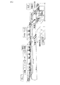
図1は、本発明において後処理として潤滑処理を行なう態様を示したものである。ワークは、「投入」で投入コンベアから設備(第1の円形回転体上)にロボットで移し替えられる(移載1)。「前処理」→「化成処理」において、ワークは第1の円形回転体の上を搬送され、化成処理の位置に到達した時点で、第1の円形回転体から併設した電解リン酸塩化成処理槽に移載され、浸漬、化成処理で化成皮膜が形成される。その後、電解リン酸塩化成処理槽から再び第1の円形回転体に戻すために移載される(移載2)。前処理において、ワークは3段で脱脂(脱脂1、2および3)された後に、3段で水洗され(水洗1、2および3)、ついでリン酸チタン系コロイド等により帯電防止等のために表面調整される。化成処理されたワークは2段の水洗を行った後(水洗4および5)、上記ロボットで第2の円形回転体上に移し替えられる(移載3)。第2の円形回転体上の潤滑処理槽で潤滑処理され、潤滑剤皮膜が形成される。ついで、ワークは潤滑処理装置から上記ロボットで「払い出し」コンベアに移載される(移載4)。 FIG. 1 shows a mode in which a lubricating treatment is performed as a post-treatment in the present invention. The workpiece is transferred from the loading conveyor to the equipment (on the first circular rotating body) by the “loading” (transfer 1). In “Pretreatment” → “Chemical conversion treatment”, when the workpiece is conveyed on the first circular rotating body and reaches the position of the chemical conversion treatment, the electrolytic phosphate chemical conversion treatment provided from the first circular rotating body is provided. It is transferred to a tank, and a chemical conversion film is formed by immersion and chemical conversion treatment. Then, it transfers in order to return again to a 1st circular rotary body from an electrolytic phosphate chemical conversion treatment tank (transfer 2). In the pre-treatment, the work is degreased in three stages (degreasing 1, 2 and 3), then washed in three stages (washing 1, 2 and 3), and then for prevention of charging by a titanium phosphate colloid or the like. Surface adjusted. The workpiece subjected to chemical conversion treatment is washed in two stages (water washing 4 and 5) and then transferred onto the second circular rotating body by the robot (transfer 3). Lubrication is performed in the lubrication treatment tank on the second circular rotating body to form a lubricant film. Next, the workpiece is transferred from the lubrication processing apparatus to the “dispensing” conveyor by the robot (transfer 4).
以下、図1および図2とともに、本発明を実施例によりさらに詳細に説明する。
実施例1
33φ×12.3L(材質:S-15C)の短い円筒状のワークを潤滑処理した。その工程は、「投入」→「前処理」→「化成処理」→「後処理」→「払い出し」の順である。設備は、「前処理」→「化成処理」を行う第1の円形回転体(円形ターンテーブル方式処理装置)と、「後処理」を行う第2の円形回転体(円形ターンテーブル方式処理装置)から構成される。
Hereinafter, the present invention will be described in more detail with reference to FIG. 1 and FIG.
Example 1
A short cylindrical workpiece of 33φ × 12.3L (material: S-15C) was lubricated. The process is in the order of “input” → “pre-processing” → “chemical conversion processing” → “post-processing” → “dispensing”. The equipment consists of a first circular rotating body (circular turntable processing device) that performs “pre-processing” → “chemical conversion processing” and a second circular rotating body (circular turntable processing device) that performs “post-processing”. Consists of
これらの円形ターンテーブル方式処理装置は、2つのワークを1つのロットとして搬送する。すなわち、搬送は、ロボットで1ケづつ2回行う方式である。ワークは、投入コンベアから1ケづつ2回で第1の円形ターンテーブル方式処理装置に移し替えられる。第1の円形ターンテーブル方式処理装置は42秒毎に1ピッチ移動する(後処理である潤滑処理のプレスは23秒毎に1ケ加工するために、その加工スピードに合せた。)。従って、ロボットによる移し替えは、42秒毎に投入コンベア→第1の円形ターンテーブル方式処理装置、第1の円形ターンテーブル方式処理装置→第2の円形ターンテーブル方式処理装置、第2の円形ターンテーブル方式処理装置→払出コンベア、の3つの搬送・移し替えを行う。 These circular turntable processing devices convey two workpieces as one lot. That is, the conveyance is a method that is performed twice by a robot. The workpiece is transferred from the input conveyor to the first circular turntable processing device twice a by one. The first circular turntable processing apparatus moves one pitch every 42 seconds (the post-lubricating press has one processing every 23 seconds, so the processing speed was adjusted). Therefore, the transfer by the robot is performed every 42 seconds by the loading conveyor → the first circular turntable processing device, the first circular turntable processing device → the second circular turntable processing device, and the second circular turn. Three types of conveyance and transfer are performed: table type processing device → payout conveyor.
処理設備では、「投入」→「前処理」→「化成処理」→「後処理」→「払い出し」の順で加工が行われ、潤滑皮膜が形成される。 In the processing equipment, processing is performed in the order of “input” → “pre-processing” → “chemical conversion processing” → “post-processing” → “dispensing”, and a lubricating film is formed.
前処理において脱脂及び水洗は、シャワーで行われる。化成処理は第1の円形ターンテーブルからワークを電解槽に移送し行われる。又、潤滑処理は、たとえば80℃浴に浸漬することで行われる。 In the pretreatment, degreasing and water washing are performed in a shower. The chemical conversion treatment is performed by transferring the workpiece from the first circular turntable to the electrolytic cell. The lubrication treatment is performed by immersing in an 80 ° C. bath, for example.
本装置の電気制御盤は、投入・払出コンベアの下側に置かれる。故に図1の本発明装置は、電気制御盤を含んだものであり(図示せず)、長さ4m、幅2.5m、高さ1.5mの大きさである。電気制御盤を含んだ装置は、設備内の電気配線に触れること無く移設・搬送が可能である。 The electric control panel of this apparatus is placed under the input / output conveyor. Therefore, the device of the present invention shown in FIG. 1 includes an electric control panel (not shown), and has a length of 4 m, a width of 2.5 m, and a height of 1.5 m. The device including the electric control panel can be moved and transported without touching the electrical wiring in the facility.
従来の潤滑処理装置は、通常、電気制御盤は別置きしており、電気制御盤まで一括しての搬送・移設は困難である。故に、設備内の電気配線に触れること無く移設・搬送が可能であることは画期的なことである。
比較例1
実施例1と同一の円筒状ワークを用いて、図2に概要を示す従来一般的な装置により、潤滑処理した。工程は、「投入」→「前処理」→「化成処理」→「後処理」→「払い出し」の順であった。設備は、投入と払出が反対側になっている。
Conventional lubrication processing apparatuses usually have a separate electric control panel, and it is difficult to carry and transfer them all at once to the electric control panel. Therefore, it is epoch-making that it can be moved and transported without touching the electrical wiring in the facility.
Comparative Example 1
The same cylindrical workpiece as in Example 1 was used for lubrication treatment by a conventional general apparatus schematically shown in FIG. The process was in the order of “input” → “pre-processing” → “chemical conversion processing” → “post-processing” → “dispensing”. The equipment is on the opposite side of input and withdrawal.
ワークの移し替えは、「投入」部、「化成処理」→「後処理」への移し替え部、「払い出し」部の3ケ所行うことが必要になる。それぞれの移し替え部は離れているため、同一のロボットを使用することは不可能である。 It is necessary to transfer the work in three places: the “input” section, the “chemical conversion process” → the “post-processing” transfer section, and the “dispensing” section. Since each transfer part is separated, it is impossible to use the same robot.
実施例1と同じように、後加工のプレスは23秒毎に1ケ加工するので、その加工スピードに合せた処理を行う場合、図2に示す装置の大きさは、長さ4.5m、幅3m、高さ1.5mであるが、電気制御盤は別置きであるのでその中には含まれない。従って、この装置を移設・搬送する際には電気工事(断線・配線)が必須である。 As in Example 1, the post-processing press processes one piece every 23 seconds. Therefore, when processing according to the processing speed is performed, the size of the apparatus shown in FIG. Although it is 3m in height and 1.5m in height, the electric control panel is not included because it is placed separately. Therefore, electrical work (disconnection / wiring) is indispensable when moving and transporting the apparatus.
以上のように、図2に示す装置は、本発明の装置に比較し大きくなり、移設・搬送の点でも不利である。 As described above, the apparatus shown in FIG. 2 is larger than the apparatus of the present invention and is disadvantageous in terms of relocation and conveyance.
本発明方法および装置によれば、処理装置の小型化に有効であり、ワークの移し替えを設備内の1ケ所に集約し、円形ターンテーブル方式の処理装置を組み合わせることで、設備の長さ方向・幅方向を集約できる。 According to the method and apparatus of the present invention, it is effective for downsizing the processing apparatus, and the transfer of workpieces is concentrated in one place in the facility, and the processing direction of the facility is combined by combining a circular turntable processing device. -The width direction can be consolidated.
Claims (11)
処理されるべき該被処理物を処理工程に投入する投入工程(A)、該被処理物の表面を前処理するための前処理工程(B)、前処理された該被処理物の表面にリン酸塩化成皮膜を形成するリン酸塩化成処理工程(C)、リン酸塩化成皮膜を形成した該被処理物の表面を後処理する後処理工程(D)、ならびに後処理された該被処理物を取り出す払出工程(E)、を含み、
投入された該被処理物を第1の円形回転体上に搭載して、該前処理工程(B)および該化成処理工程(C)を終了した後に、化成処理された被処理物を第1の円形回転体から第2の円形回転体上に移載し、ついで該後処理工程(D)を行ない、かつ
処理されるべき該被処理物の投入、リン酸塩化成処理された被処理物の後処理工程への移載および後処理された該被処理物の取り出しをロボットで行なう、
ことを特徴とする電解リン酸塩化成処理方法。 In the electrolytic phosphate chemical treatment method for forming a phosphate chemical conversion film on the surface of an object to be treated, the electrolytic phosphate chemical treatment method includes:
An input step (A) for feeding the workpiece to be treated into the treatment step, a pretreatment step (B) for pretreating the surface of the workpiece, and a surface of the pretreated workpiece. A phosphate chemical conversion treatment step (C) for forming a phosphate chemical conversion film, a post-treatment step (D) for post-processing the surface of the workpiece on which the phosphate chemical conversion coating has been formed, and the post-treatment target A payout step (E) for taking out the processed product,
The charged object to be processed is mounted on the first circular rotating body, and after the pretreatment step (B) and the chemical conversion treatment step (C) are finished, the chemical conversion processed object to be processed is the first. Transferred from the circular rotator to the second circular rotator, and then the post-treatment step (D) is performed, and the workpiece to be treated is charged, and the phosphate chemical-treated workpiece Transfer to the post-processing step and take out the post-processed object by a robot.
An electrolytic phosphate chemical treatment method characterized by the above.
該ロボットは、(ア)処理されるべき該被処理物を第1の円形回転体に投入、搭載し;(イ)該被処理物の表面を清浄化するための前処理および前処理された該被処理物の表面にリン酸塩化成皮膜を形成するリン酸塩化成処理された、被処理物を、第1の円形回転体から第2の円形回転体に移載し;ついで(ウ)表面を後処理された被処理物を第2の円形回転体から取り出す、ように構成されてなる、
電解リン酸塩化成処理装置。 An electrolytic phosphate chemical treatment apparatus for forming a phosphate chemical conversion film on the surface of an object to be treated, the electrolytic phosphate chemical treatment apparatus including first and second circular rotating bodies and a robot,
The robot (a) loads and mounts the workpiece to be treated on the first circular rotating body; (b) pretreatment and pretreatment to clean the surface of the workpiece A phosphate chemical conversion treatment to form a phosphate chemical film on the surface of the workpiece is transferred from the first circular rotating body to the second circular rotating body; The object to be processed whose surface has been post-processed is configured to be taken out from the second circular rotating body.
Electrolytic phosphate chemical treatment equipment.
Priority Applications (1)
| Application Number | Priority Date | Filing Date | Title |
|---|---|---|---|
| JP2008246392A JP5153544B2 (en) | 2008-09-25 | 2008-09-25 | Electrolytic phosphate chemical treatment method and apparatus therefor |
Applications Claiming Priority (1)
| Application Number | Priority Date | Filing Date | Title |
|---|---|---|---|
| JP2008246392A JP5153544B2 (en) | 2008-09-25 | 2008-09-25 | Electrolytic phosphate chemical treatment method and apparatus therefor |
Publications (2)
| Publication Number | Publication Date |
|---|---|
| JP2010077486A true JP2010077486A (en) | 2010-04-08 |
| JP5153544B2 JP5153544B2 (en) | 2013-02-27 |
Family
ID=42208242
Family Applications (1)
| Application Number | Title | Priority Date | Filing Date |
|---|---|---|---|
| JP2008246392A Expired - Fee Related JP5153544B2 (en) | 2008-09-25 | 2008-09-25 | Electrolytic phosphate chemical treatment method and apparatus therefor |
Country Status (1)
| Country | Link |
|---|---|
| JP (1) | JP5153544B2 (en) |
Cited By (2)
| Publication number | Priority date | Publication date | Assignee | Title |
|---|---|---|---|---|
| JP2012505965A (en) * | 2008-10-20 | 2012-03-08 | サムウォン アルテック カンパニー,リミテッド | Metal anodizing treatment method and system |
| CN110029385A (en) * | 2019-04-07 | 2019-07-19 | 王绪军 | The surface anodization processing unit of aluminium alloy processing |
Citations (5)
| Publication number | Priority date | Publication date | Assignee | Title |
|---|---|---|---|---|
| JPS5115116U (en) * | 1974-07-19 | 1976-02-03 | ||
| JPS58147600A (en) * | 1982-02-27 | 1983-09-02 | Enshu Ltd | High speed electrolytic defatting device of dipping type |
| JPS61143598A (en) * | 1984-12-17 | 1986-07-01 | Mitsubishi Heavy Ind Ltd | Continuous inline plating method |
| JP2000228388A (en) * | 1998-12-01 | 2000-08-15 | Ideya:Kk | Semiconductor equipment |
| JP2007023334A (en) * | 2005-07-15 | 2007-02-01 | Denso Corp | Electrolytic phosphate chemical treatment method |
-
2008
- 2008-09-25 JP JP2008246392A patent/JP5153544B2/en not_active Expired - Fee Related
Patent Citations (5)
| Publication number | Priority date | Publication date | Assignee | Title |
|---|---|---|---|---|
| JPS5115116U (en) * | 1974-07-19 | 1976-02-03 | ||
| JPS58147600A (en) * | 1982-02-27 | 1983-09-02 | Enshu Ltd | High speed electrolytic defatting device of dipping type |
| JPS61143598A (en) * | 1984-12-17 | 1986-07-01 | Mitsubishi Heavy Ind Ltd | Continuous inline plating method |
| JP2000228388A (en) * | 1998-12-01 | 2000-08-15 | Ideya:Kk | Semiconductor equipment |
| JP2007023334A (en) * | 2005-07-15 | 2007-02-01 | Denso Corp | Electrolytic phosphate chemical treatment method |
Cited By (2)
| Publication number | Priority date | Publication date | Assignee | Title |
|---|---|---|---|---|
| JP2012505965A (en) * | 2008-10-20 | 2012-03-08 | サムウォン アルテック カンパニー,リミテッド | Metal anodizing treatment method and system |
| CN110029385A (en) * | 2019-04-07 | 2019-07-19 | 王绪军 | The surface anodization processing unit of aluminium alloy processing |
Also Published As
| Publication number | Publication date |
|---|---|
| JP5153544B2 (en) | 2013-02-27 |
Similar Documents
| Publication | Publication Date | Title |
|---|---|---|
| CA3018273C (en) | Hot-dip galvanization system and hot-dip galvanization method | |
| US10982308B2 (en) | Hot-dip galvanization system and hot-dip galvanization method, in particular for mass production | |
| JP2008540845A5 (en) | ||
| CA3015539C (en) | Hot-dip galvanization system and hot-dip galvanization method | |
| JP5153544B2 (en) | Electrolytic phosphate chemical treatment method and apparatus therefor | |
| CN106835088A (en) | A kind of chemical nickel and gold production line and production technology | |
| EP3329036A1 (en) | Process for metallizing plastic surfaces | |
| TW539744B (en) | Aqueous lubricant of one process type used for high efficient cold forging | |
| JP2013066901A (en) | Method for forming lubricating film and method for lubrication treatment | |
| KR20180063665A (en) | Plating apparatus | |
| KR101523546B1 (en) | Method for manufacturing non phosphate coated metal material for cold heading plastic working | |
| CN105112903A (en) | Method for phosphating treatment of clamp for wear-resistant hopper processing | |
| CN102220576A (en) | Magnesium alloy surface chemical treatment solution and surface chemical treatment method | |
| CN104047005A (en) | Method for removing oil of copper and copper alloy | |
| JP5267526B2 (en) | Plating apparatus and plating method | |
| JP4419928B2 (en) | Electrolytic phosphate chemical treatment method | |
| US20080011323A1 (en) | Method For Removing Laser Scales | |
| JP6629979B2 (en) | Method for producing a steel product having a Zn coating and a tribologically active layer deposited on the coating, and a steel product produced according to the method | |
| CN110621807A (en) | Method for surface modification of at least one component and reactor device for carrying out the method | |
| CN103451638A (en) | Pressure phosphating method for enhancing surface oxidation resistance of steel and iron materials | |
| JP5278391B2 (en) | Electrolytic phosphate chemical treatment method | |
| KR20150120680A (en) | Mechanical Plating Method | |
| GB2048951A (en) | Method of sewageless metallization | |
| JP2012219365A (en) | Manufacturing method of metallic material for plastic woking and worked metal product | |
| JPS61199514A (en) | Cold working methods for metals |
Legal Events
| Date | Code | Title | Description |
|---|---|---|---|
| A621 | Written request for application examination |
Free format text: JAPANESE INTERMEDIATE CODE: A621 Effective date: 20110106 |
|
| A977 | Report on retrieval |
Free format text: JAPANESE INTERMEDIATE CODE: A971007 Effective date: 20120809 |
|
| A131 | Notification of reasons for refusal |
Free format text: JAPANESE INTERMEDIATE CODE: A131 Effective date: 20120814 |
|
| A521 | Request for written amendment filed |
Free format text: JAPANESE INTERMEDIATE CODE: A523 Effective date: 20121012 |
|
| TRDD | Decision of grant or rejection written | ||
| A01 | Written decision to grant a patent or to grant a registration (utility model) |
Free format text: JAPANESE INTERMEDIATE CODE: A01 Effective date: 20121106 |
|
| A61 | First payment of annual fees (during grant procedure) |
Free format text: JAPANESE INTERMEDIATE CODE: A61 Effective date: 20121204 |
|
| FPAY | Renewal fee payment (event date is renewal date of database) |
Free format text: PAYMENT UNTIL: 20151214 Year of fee payment: 3 |
|
| R150 | Certificate of patent or registration of utility model |
Ref document number: 5153544 Country of ref document: JP Free format text: JAPANESE INTERMEDIATE CODE: R150 Free format text: JAPANESE INTERMEDIATE CODE: R150 |
|
| R250 | Receipt of annual fees |
Free format text: JAPANESE INTERMEDIATE CODE: R250 |
|
| R250 | Receipt of annual fees |
Free format text: JAPANESE INTERMEDIATE CODE: R250 |
|
| R250 | Receipt of annual fees |
Free format text: JAPANESE INTERMEDIATE CODE: R250 |
|
| R250 | Receipt of annual fees |
Free format text: JAPANESE INTERMEDIATE CODE: R250 |
|
| S531 | Written request for registration of change of domicile |
Free format text: JAPANESE INTERMEDIATE CODE: R313531 |
|
| S533 | Written request for registration of change of name |
Free format text: JAPANESE INTERMEDIATE CODE: R313533 |
|
| R350 | Written notification of registration of transfer |
Free format text: JAPANESE INTERMEDIATE CODE: R350 |
|
| R250 | Receipt of annual fees |
Free format text: JAPANESE INTERMEDIATE CODE: R250 |
|
| R250 | Receipt of annual fees |
Free format text: JAPANESE INTERMEDIATE CODE: R250 |
|
| R250 | Receipt of annual fees |
Free format text: JAPANESE INTERMEDIATE CODE: R250 |
|
| LAPS | Cancellation because of no payment of annual fees |