JP2010077600A - Cutting device and removal method for existing pile - Google Patents
Cutting device and removal method for existing pile Download PDFInfo
- Publication number
- JP2010077600A JP2010077600A JP2008243919A JP2008243919A JP2010077600A JP 2010077600 A JP2010077600 A JP 2010077600A JP 2008243919 A JP2008243919 A JP 2008243919A JP 2008243919 A JP2008243919 A JP 2008243919A JP 2010077600 A JP2010077600 A JP 2010077600A
- Authority
- JP
- Japan
- Prior art keywords
- wire saw
- existing pile
- cutting
- inner casing
- casing
- Prior art date
- Legal status (The legal status is an assumption and is not a legal conclusion. Google has not performed a legal analysis and makes no representation as to the accuracy of the status listed.)
- Granted
Links
- 238000005520 cutting process Methods 0.000 title claims abstract description 132
- 238000000034 method Methods 0.000 title claims abstract description 46
- 230000001681 protective effect Effects 0.000 claims description 51
- 230000002093 peripheral effect Effects 0.000 claims description 40
- 239000004576 sand Substances 0.000 claims description 37
- XLYOFNOQVPJJNP-UHFFFAOYSA-N water Substances O XLYOFNOQVPJJNP-UHFFFAOYSA-N 0.000 claims description 37
- 239000013013 elastic material Substances 0.000 claims description 5
- 230000005484 gravity Effects 0.000 abstract description 4
- 239000013049 sediment Substances 0.000 abstract 2
- 239000000463 material Substances 0.000 description 20
- 238000003780 insertion Methods 0.000 description 14
- 230000037431 insertion Effects 0.000 description 14
- 238000010276 construction Methods 0.000 description 13
- 229920001875 Ebonite Polymers 0.000 description 8
- 239000002184 metal Substances 0.000 description 7
- 238000009412 basement excavation Methods 0.000 description 4
- 229910000831 Steel Inorganic materials 0.000 description 3
- 239000010959 steel Substances 0.000 description 3
- JEIPFZHSYJVQDO-UHFFFAOYSA-N iron(III) oxide Inorganic materials O=[Fe]O[Fe]=O JEIPFZHSYJVQDO-UHFFFAOYSA-N 0.000 description 2
- 230000002265 prevention Effects 0.000 description 2
- 238000006243 chemical reaction Methods 0.000 description 1
- 238000007599 discharging Methods 0.000 description 1
- 238000005553 drilling Methods 0.000 description 1
- 230000000694 effects Effects 0.000 description 1
- NJPPVKZQTLUDBO-UHFFFAOYSA-N novaluron Chemical compound C1=C(Cl)C(OC(F)(F)C(OC(F)(F)F)F)=CC=C1NC(=O)NC(=O)C1=C(F)C=CC=C1F NJPPVKZQTLUDBO-UHFFFAOYSA-N 0.000 description 1
- 238000005086 pumping Methods 0.000 description 1
- 238000007790 scraping Methods 0.000 description 1
Images


Landscapes
- Placing Or Removing Of Piles Or Sheet Piles, Or Accessories Thereof (AREA)
Abstract
Description
本発明は、地中に埋設された既存杭の切断装置、及び既存杭を切断して撤去する撤去工法に関する。 The present invention relates to a cutting device for an existing pile buried in the ground, and a removal method for cutting and removing the existing pile.
建築物の基礎として又は地盤改良のために地中に杭が打ち込まれるが、既存建築物を解体して新たに建築物を建築し、又は新たな地盤改良工事を行う場合には、既存杭が邪魔となり撤去する必要が生じる。不要となった既存杭を撤去する工法として、既存杭を上端から破壊していく工法が広く用いられているが、現場で発生する膨大な破片を処分するために甚大な労力,時間及び費用を要し、又は、長期間に亘って大きな騒音や振動を発生する問題があった。また、杭を引き抜く工法も知られてはいるものの、長尺又は大径の杭には適用できず、一般性に乏しい問題があった。そのため、既存杭を上端から順次切断して除去する工法、又は当該工法のための装置が開示されている。 Pile is driven into the ground as the foundation of the building or for ground improvement, but when dismantling the existing building and building a new building, or performing new ground improvement construction, It gets in the way and needs to be removed. As a method of removing existing piles that are no longer needed, a method of destroying existing piles from the top is widely used, but it takes tremendous labor, time and cost to dispose of huge pieces of debris generated at the site. In other words, there has been a problem of generating large noises and vibrations over a long period of time. Moreover, although the construction method which pulls out a pile is also known, it was not applicable to a long or large diameter pile, and there was a problem with poor generality. Therefore, the construction method which cuts and removes an existing pile sequentially from an upper end, or the apparatus for the construction method is indicated.
例えば、既存の基礎杭の周りに同基礎杭よりも径の大きな鋼管製のケーシングを圧入して同ケーシングと上記基礎杭との間の土砂を掻き出して空間を形成し、同空間にエンドレス形状のワイヤーソーを有するワイヤーソー装置を挿入し、同ワイヤーソー装置を駆動し上記基礎杭を所望の長さに輪切りしてから順次取り出すようにしたことを特徴とする既存基礎杭の切断除去工法、及び該工法に用いられる既存基礎杭切断除去装置が開示されている(例えば、特許文献1参照)。 For example, a steel pipe casing having a diameter larger than that of the foundation pile is press-fitted around the existing foundation pile, and the space between the casing and the foundation pile is scraped to form a space. Inserting a wire saw device having a wire saw, driving the wire saw device, cutting the foundation pile to a desired length and then sequentially removing it, and cutting and removing the existing foundation pile, An existing foundation pile cutting and removing device used in the construction method is disclosed (for example, see Patent Document 1).
また、地中に埋設された既存杭を切断して撤去する既存杭撤去工法であって、前記既存杭の外径よりも大きい内径を備えるケーシングを、前記既存杭とほぼ同軸にして、所定の地中深度まで圧入する第1の工程と、前記既存杭と前記ケーシングの間の土砂を除去して、前記既存杭の周囲に空間を設ける第2の工程と、前記空間外に設けられたワイヤーソー駆動装置によって駆動される前記ワイヤーソーを可動に案内して、前記既存杭を水平方向に切断するワイヤーソー案内手段を、前記空間の所定深度位置に配設する第3の工程と、前記ワイヤーソーによって、前記所定深度位置で前記既存杭を水平方向に切断する第4の工程と、前記切断された既存杭を上方に吊り上げて前記ケーシングの外部に搬出する第5の工程と、からなり、前記第1〜5の工程を順次行って、前記既存杭を必要長さだけ撤去する既存杭撤去工法、及び該工法に用いられる柱状構造物の切断装置が開示されている(例えば、特許文献2参照)。 Further, it is an existing pile removal method for cutting and removing an existing pile buried in the ground, and a casing having an inner diameter larger than the outer diameter of the existing pile is substantially coaxial with the existing pile, and a predetermined A first step of press-fitting to an underground depth; a second step of removing earth and sand between the existing pile and the casing to provide a space around the existing pile; and a wire provided outside the space A third step of arranging wire saw guide means for guiding the wire saw driven by a saw drive device movably and cutting the existing pile in a horizontal direction at a predetermined depth in the space; and the wire A fourth step of horizontally cutting the existing pile at the predetermined depth position by a saw; and a fifth step of lifting the cut existing pile upward and carrying it out of the casing. The first The fifth step sequentially performed, existing pile removal method to remove only the necessary length of the existing pile, and cutting device of the columnar structures used in 該工 method is disclosed (e.g., see Patent Document 2).
しかしながら、上記特許文献に記載の工法は、何れも既存杭と直接接触する土砂を掻き出した後に前記既存杭を切断する工法であって、ワイヤーソー上方の切断片に掛かる重力のためにワイヤーソーに負荷が掛かり、ワイヤーソーが噛み込んで動かせなくなり、更にはワイヤーソーが破断してしまう虞がある。 However, all of the construction methods described in the above-mentioned patent documents are methods of cutting the existing pile after scraping the earth and sand that are in direct contact with the existing pile, and are applied to the wire saw due to the gravity applied to the cutting piece above the wire saw. There is a risk that the load is applied, the wire saw is bitten and cannot be moved, and the wire saw is broken.
ワイヤーソーの噛み込みを防ぐために、同一深さにおける複数箇所を切断した後、切断されていない軸付近の一部を破断することも開示されているものの、切断途中の既存杭からワイヤーソーを外すことは現実には困難で、却ってワイヤーソー破断の危険が増す。それを回避するために、ワイヤーソー上方の切断片を吊上げ続け、又は切断部に楔を打ち込むことも可能ではあるが、これらの方法を適用するためには、大掛かりな装置や特殊な装置が必要であり、また、手順が複雑なために甚大な手間を要する。 To prevent biting of the wire saw, it is disclosed that after cutting a plurality of places at the same depth and then breaking a part near the shaft that is not cut, the wire saw is removed from the existing pile in the middle of cutting. This is difficult in practice and increases the risk of breaking the wire saw. In order to avoid this, it is possible to continue lifting the cutting piece above the wire saw or to drive a wedge into the cutting portion, but in order to apply these methods, a large-scale device or a special device is required. In addition, since the procedure is complicated, a great deal of labor is required.
これらの問題点に鑑み、本発明は、ワイヤーソーに掛かる負荷を軽減することによって、ワイヤーソーの噛み込み及び破断を回避しながら、既存杭を簡便に切断できる切断装置を提供することを課題とする。また、ワイヤーソーの噛み込み及び破断を回避しつつ、既存杭を簡便に切断し撤去する撤去工法を提供することを課題とする。 In view of these problems, an object of the present invention is to provide a cutting device that can easily cut an existing pile while avoiding biting and breaking of the wire saw by reducing the load applied to the wire saw. To do. It is another object of the present invention to provide a removal method for easily cutting and removing an existing pile while avoiding biting and breaking of a wire saw.
上記課題を解決する本発明は、
[1]地中に埋設された既存杭を切断するための切断装置であって、
既存杭の外径よりも大きな内径を有する管状の内側ケーシング,内側ケーシングの外径よりも大きな内径を有し内側ケーシングと略同軸に配置された管状の外側ケーシング,内側ケーシングの外周面の外方に配置され鉛直方向に回動自在な2個の主ガイドプーリー,内側ケーシングの周壁に穿設された切断用窓,内側ケーシングの外周面の外方に配置された回転軸に水平方向に回動自在に軸止され、切断用窓と略同一の高さ位置に設けられた2個の方向変換プーリー,内側ケーシングの内周面における切断用窓と略同一の高さ位置に立設された係止部,駆動装置から主ガイドプーリー、次いで方向変換プーリーに架け渡されて切断用窓から内側ケーシング内に導かれたワイヤーソー,並びに内側ケーシングの外周面に付設され主ガイドプーリー,方向変換プーリー,及び切断用窓を覆う保護カバーを具え、
ワイヤーソーの内側ケーシング内の部分が、係止部に係止可能とされてなることを特徴とする既存杭の切断装置である。
The present invention for solving the above problems
[1] A cutting device for cutting existing piles buried in the ground,
Tubular inner casing having an inner diameter larger than the outer diameter of the existing pile, Tubular outer casing having an inner diameter larger than the outer diameter of the inner casing and arranged substantially coaxially with the inner casing, outward of the outer peripheral surface of the
It is the existing pile cutting device characterized in that a portion in the inner casing of the wire saw can be locked to the locking portion.
[2]係止部が、弾性を有する材質で作成されてなる上記[1]に記載の既存杭の切断装置である。 [2] The existing pile cutting apparatus according to [1], wherein the engaging portion is made of an elastic material.
[3]前記保護カバーの内部に連通する導水管が設けられてなる上記[1]又は[2]に記載の既存杭の切断装置である。 [3] The existing pile cutting apparatus according to [1] or [2], wherein a water guide pipe communicating with the inside of the protective cover is provided.
[4]主ガイドプーリー及び方向変換プーリーの、半径がワイヤーソーの最大断面直径の5倍以上8倍以下,溝深さがワイヤーソーの最大断面直径の1.5倍以上3.0倍以下,且つ外周における溝の開口幅がワイヤーソーの最大断面直径の1.5倍以上3.0倍以下であることを特徴とする上記[1]乃至[3]の何れかに記載の既存杭の切断装置である。 [4] The radius of the main guide pulley and direction change pulley is 5 to 8 times the maximum cross-sectional diameter of the wire saw, and the groove depth is 1.5 to 3.0 times the maximum cross-sectional diameter of the wire saw. And the opening width of the groove | channel on the outer periphery is 1.5 times or more and 3.0 times or less of the largest cross-sectional diameter of a wire saw, The cutting of the existing pile in any one of said [1] thru | or [3] characterized by the above-mentioned. Device.
また、
[5]地中に埋設された既存杭の撤去工法であって、
(A)既存杭の外径よりも大きな内径を有する管状の外側ケーシングを、既存杭と略同軸にして地中に圧入する工程
(B)既存杭の外径より大きな内径と外側ケーシングの内径より小さな外径を有し、外周面の外方に配置され鉛直方向に回動自在な2個の主ガイドプーリー,周壁に穿設された切断用窓,外周面の外方に配置された回転軸に水平方向に回動自在に軸止され、切断用窓と略同一の高さ位置に設けられた2個の方向変換プーリー,内周面における切断用窓と略同一の高さ位置に立設された係止部,駆動装置から主ガイドプーリー、次いで方向変換プーリーに架け渡されて切断用窓から内側ケーシング内に導かれたワイヤーソー,並びに外周面に付設され主ガイドプーリー,方向変換プーリー,及び切断用窓を覆う保護カバーを具えた管状の内側ケーシングを、既存杭及び外側ケーシングと略同軸にして地中に圧入する工程
(C)内側ケーシングと外側ケーシングの間の土砂の少なくとも一部を除去する工程
(D)ワイヤーソーの係止を解く工程
(E)ワイヤーソーで既存杭を切断する工程
(F)工程(E)で切断された既存杭の切断片を、吊上げて撤去する工程
順に行われる上記工程(A)乃至(F)を含む既存杭の撤去工法である。
Also,
[5] A method for removing existing piles buried in the ground,
(A) A step of pressing a tubular outer casing having an inner diameter larger than the outer diameter of the existing pile into the ground substantially coaxially with the existing pile (B) An inner diameter larger than the outer diameter of the existing pile and an inner diameter of the outer casing Two main guide pulleys that have a small outer diameter and are arranged outside the outer peripheral surface and are rotatable in the vertical direction, a cutting window drilled in the peripheral wall, and a rotary shaft arranged outside the outer peripheral surface Two direction-changing pulleys, which are pivotally supported in a horizontal direction and provided at substantially the same height as the cutting window, and are erected at substantially the same height as the cutting window on the inner peripheral surface. A locking saw, a main guide pulley from the driving device, and then a wire saw that is stretched over the direction change pulley and led from the cutting window into the inner casing, and a main guide pulley that is attached to the outer peripheral surface, a direction change pulley, And a protective cover covering the cutting window (C) Step of removing at least a part of earth and sand between inner casing and outer casing (D) Locking of wire saw (E) The process (A) thru | or (F) performed in order of the process which lifts and removes the cut piece of the existing pile cut | disconnected by the process (E) process (E) which cuts an existing pile with a wire saw This is a method of removing existing piles including
[6]係止部が弾性を有する材質で作成されてなり、ワイヤーソーの駆動を開始し又はワイヤーソーに張力を加えることによって工程(D)が行われる上記[5]に記載の既存杭の撤去工法である。 [6] The existing pile according to [5], wherein the engaging portion is made of an elastic material, and the step (D) is performed by starting driving of the wire saw or applying tension to the wire saw. It is a removal method.
[7]前記保護カバーの内部に、導水管を通して水流を導きながら、工程(E)が行われることを特徴とする上記[5]又は[6]に記載の既存杭の撤去工法である。 [7] The method for removing an existing pile according to the above [5] or [6], wherein the step (E) is performed while guiding a water flow through a water conduit inside the protective cover.
[8]主ガイドプーリー及び方向変換プーリーの、半径がワイヤーソーの最大断面直径の5倍以上8倍以下,溝深さがワイヤーソーの最大断面直径の1.5倍以上3.0倍以下,且つ外周における溝の開口幅がワイヤーソーの最大断面直径の1.5倍以上3.0倍以下である上記[5]乃至[7]の何れかに記載の既存杭の撤去工法である。 [8] The radius of the main guide pulley and the direction change pulley is 5 to 8 times the maximum cross-sectional diameter of the wire saw, and the groove depth is 1.5 to 3.0 times the maximum cross-sectional diameter of the wire saw. And it is the removal method of the existing pile in any one of said [5] thru | or [7] whose opening width of the groove | channel in an outer periphery is 1.5 to 3.0 times the largest cross-sectional diameter of a wire saw.
本発明に係る既存杭の切断装置又は既存杭の撤去工法によれば、内側ケーシング内に土砂を保持したまま既存杭を切断できるから、当該切断の間、切断片は前記土砂に支持された状態に維持される。また、ワイヤーソーで切断されて生じた隙間に周囲の土砂が侵入し、該土砂が切断片を支持することも期待される。これらの理由により、前記切断片に掛かる重力のためにワイヤーソーに負荷が掛かることが回避され、ワイヤーソーの噛み込み及び破断を防止できる。 According to the existing pile cutting apparatus or the existing pile removing method according to the present invention, the existing pile can be cut while holding the earth and sand in the inner casing, so that the cut piece is supported by the earth and sand during the cutting. Maintained. In addition, it is expected that surrounding earth and sand enter a gap generated by cutting with a wire saw, and that the earth and sand support the cut piece. For these reasons, it is avoided that a load is applied to the wire saw due to the gravity applied to the cut piece, and it is possible to prevent the wire saw from being bitten and broken.
既存杭が土砂に支持された状態で切断が行われるから、切断片を吊上げ又は切断部に楔を打ち込む等の特別な操作によって既存杭を支持することなく、1回の切断操作で切断を完遂できる。既存杭の軸付近の一部を残して複数箇所を切断することを要しないから、切断箇所から外すことによるワイヤーソーの破断を回避できる。 Since cutting is performed with the existing pile supported by the earth and sand, cutting is completed by a single cutting operation without supporting the existing pile by special operations such as lifting the cutting piece or driving a wedge into the cutting part. it can. Since it is not necessary to cut a plurality of places except for a part near the axis of the existing pile, it is possible to avoid breakage of the wire saw due to removal from the cut place.
叙上の様に、ワイヤーソーの噛み込み及び破断を防止できるから、ワイヤーソーの交換頻度を低減し、費用を抑制できる。 As described above, since the wire saw can be prevented from being bitten and broken, the frequency of replacing the wire saw can be reduced and the cost can be suppressed.
また、内側ケーシングの内周に沿って設けられた係止部にワイヤーソーを係止した状態で内側ケーシングを地中に圧入できるから、内側ケーシングを圧入するのみでワイヤーソーを目的の切断深さに配置し、既存杭の切断を開始できる。 In addition, since the inner casing can be press-fitted into the ground with the wire saw locked to the locking portion provided along the inner circumference of the inner casing, the wire saw can be cut to a desired depth only by press-fitting the inner casing. And can start cutting existing piles.
主ガイドプーリー及び方向変換プーリーが保護カバーで覆われているから、内側ケーシングを地中に圧入し又はワイヤーソーで既存杭を切断する際に掛かる負荷を低減でき、前記プーリーの損傷を防止できる。 Since the main guide pulley and the direction change pulley are covered with the protective cover, the load applied when the inner casing is press-fitted into the ground or the existing pile is cut with a wire saw can be reduced, and damage to the pulley can be prevented.
外側ケーシング外からの土砂の流入を防ぐことができるから、内側ケーシングの圧入,既存杭の切断,及び内側ケーシングの引き抜きを繰り返し、既存杭を多数箇所で切断する作業を容易に行うことができる。これにより一回の切断作業で生じる切断片の重量が抑制され、前記切断片を施工現場から搬出し、施工現場とは異なる場所で破砕等の手段により処分することが容易に行える。施工現場付近で前記切断片を処分する必要が無いから、既存杭の切断作業を短期間で完遂できる。 Since the inflow of earth and sand from the outside of the outer casing can be prevented, it is possible to easily perform the work of cutting the existing pile at a number of locations by repeatedly press-fitting the inner casing, cutting the existing pile, and pulling out the inner casing. Thereby, the weight of the cut piece generated by one cutting operation is suppressed, and the cut piece can be easily taken out from the construction site and disposed of by means such as crushing at a place different from the construction site. Since it is not necessary to dispose of the cut piece near the construction site, the cutting work of the existing pile can be completed in a short period of time.
また、既存杭を全て切断し撤去し、外側ケーシング以外の全部材を引き抜いた後に、外側ケーシングを引き抜きながら施工で生じた掘削孔を埋め戻すことによって、施工現場の地盤の液状化を防止することができる。 In addition, after cutting and removing all existing piles and pulling out all members other than the outer casing, the ground hole at the construction site is prevented from becoming liquefied by pulling out the outer casing and backfilling the excavation holes generated in the construction. Can do.
上記[2]又は[6]に記載の発明によれば、係止部が弾性を有する材質で作成されているから、ワイヤーソーの駆動を開始し、又は主ガイドプーリーを介してワイヤーソーに張力を加えるのみで係止を解き、特別な操作を加えることなく既存杭の切断を開始できる。また、係止部が弾性を有する材質で作成されているから、係止を解く操作によって係止部が破損せず、当該切断装置を繰り返し使用できる。 According to the invention described in [2] or [6] above, since the locking portion is made of a material having elasticity, the wire saw starts to be driven or tension is applied to the wire saw via the main guide pulley. Unlocking just by adding can start cutting existing piles without adding any special operations. Moreover, since the latching | locking part is produced with the material which has elasticity, the latching | locking part is not damaged by the operation which cancels | releases latching, and the said cutting device can be used repeatedly.
上記[3]又は[7]に記載の発明によれば、導水管を通じて保護カバー内に水流を導くことによって、該水流は、切断用窓又は保護カバーに設けられたワイヤーソー挿通孔から排出される。前記水流は、保護カバー内に侵入した土砂を切断用窓又はワイヤーソー挿通孔から排出し、また、保護カバー内への土砂の侵入を防止する役割を担う。これによって、ガイドプーリー及び方向変換プーリーの土砂による回転負荷が低減され、ワイヤーソーによる既存杭の切断をより円滑に行うことができる。前記水流としては高圧の水流を用いることが好ましく、それにより、上記効果が一層顕著に現れる。 According to the invention described in [3] or [7] above, the water flow is discharged from the wire saw insertion hole provided in the cutting window or the protective cover by guiding the water flow into the protective cover through the water conduit. The The water stream plays a role of discharging the earth and sand that has entered the protective cover from the cutting window or the wire saw insertion hole, and preventing the earth and sand from entering the protective cover. Thereby, the rotational load by the earth and sand of a guide pulley and a direction change pulley is reduced, and the existing pile can be cut | disconnected more smoothly by a wire saw. As the water flow, it is preferable to use a high-pressure water flow, and thereby the above-described effect is more remarkable.
上記[4]又は[8]に記載の発明によれば、従来のワイヤーソー用プーリーよりも小径のプーリーが用いられているから、保護カバーのサイズを小さくすることができ、内側ケーシングを地中に圧入する際に保護カバー,主ガイドプーリー,及び方向変換プーリーに掛かる負荷を低減し、前記部材の消耗を回避できる。また、プーリーが小径化されているから、万一保護カバー内に土砂が侵入しても該土砂による回転負荷が小さく、プーリーは安定且つ円滑に回転可能である。 According to the invention described in [4] or [8] above, since a pulley having a smaller diameter than that of a conventional wire saw pulley is used, the size of the protective cover can be reduced, and the inner casing can be grounded. It is possible to reduce the load applied to the protective cover, the main guide pulley, and the direction changing pulley when press-fitting into the cover, thereby avoiding wear of the member. Further, since the pulley has a small diameter, even if earth and sand enter the protective cover, the rotational load caused by the earth and sand is small, and the pulley can rotate stably and smoothly.
プーリーの溝深さが従来のプーリーよりも深くされているから、小径のプーリーであるにも関わらず、ワイヤーソーが外れ難い。また、プーリーの外周における溝の開口幅が従来よりも広くされているから、ワイヤーソーがプーリーの軸方向にぶれたとしても外れ難い。 Since the groove depth of the pulley is deeper than that of the conventional pulley, the wire saw is difficult to come off despite being a small-diameter pulley. Moreover, since the opening width of the groove | channel in the outer periphery of a pulley is made wider than before, even if a wire saw shakes in the axial direction of a pulley, it is hard to come off.
以下、本発明の実施の形態を、図面を参照しつつ詳しく説明するが、本発明はこれに限定されるものではない。 Hereinafter, embodiments of the present invention will be described in detail with reference to the drawings, but the present invention is not limited thereto.
まず、本発明に係る既存杭の切断装置について説明する。 First, the existing pile cutting apparatus according to the present invention will be described.
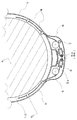
図1は、本発明に係る既存杭の撤去工法を示す側面図である。図2は、内側ケーシングの保護カバー付近を示す要部横断面図である。図3は、保護カバーを切り開いて示す、内側ケーシングの保護カバー付近の要部正面図である。図4は図2のX−X線断面を示す要部端面図である。図5は、既存杭の切断を開始する前の状態を示す横断面図であり、図6は、既存杭を切断している状態を示す横断面図である。尚、図中の白抜き矢印は、ワイヤーソーの駆動方向(移動方向)を示す。 FIG. 1 is a side view showing an existing pile removal method according to the present invention. FIG. 2 is a cross-sectional view of the main part showing the vicinity of the protective cover of the inner casing. FIG. 3 is a front view of a main part near the protective cover of the inner casing, with the protective cover cut open. FIG. 4 is an end view of a main part showing a cross section taken along line XX of FIG. FIG. 5 is a cross-sectional view showing a state before the cutting of the existing pile is started, and FIG. 6 is a cross-sectional view showing a state where the existing pile is being cut. In addition, the white arrow in a figure shows the drive direction (movement direction) of a wire saw.
本発明に係る既存杭の切断装置は、地中に埋設された既存杭10を切断するための切断装置であって、既存杭10の外径よりも大きな内径を有する管状の内側ケーシング1,内側ケーシング1の外径よりも大きな内径を有し内側ケーシング1と略同軸に配置された管状の外側ケーシング2を具えている。
The cutting device for an existing pile according to the present invention is a cutting device for cutting an existing
内側ケーシング1の外周面の外方には、鉛直方向に回動自在な2個の主ガイドプーリー3,3が配置されている。内側ケーシング1の周壁には、切断用窓5が穿設されている。内側ケーシング1の外周面の外方に配置された回転軸に、2個の方向変換プーリー4,4が、水平方向に回動自在に軸止されて設けられていて、方向変換プーリー4,4の高さ位置は、切断用窓5の高さ位置と略同一とされている。内側ケーシング1の外周面には、主ガイドプーリー3,3,方向変換プーリー4,4,及び切断用窓5を覆う保護カバー6が付設されている。
Two main guide pulleys 3 and 3 that are rotatable in the vertical direction are arranged outside the outer peripheral surface of the
内側ケーシング1の内周面には、切断用窓5と略同一の高さ位置に、係止部8,…が立設されている。
On the inner peripheral surface of the
地上に配置された駆動装置(図示せず)で駆動されるワイヤーソー9が、前記駆動装置から主ガイドプーリー3,3、次いで方向変換プーリー4,4に架け渡され、切断用窓5から内側ケーシング1内に導かれている。ワイヤーソー9の、内側ケーシング1内の部分は、係止部8,…に係止可能とされている。
A wire saw 9 driven by a drive device (not shown) arranged on the ground is bridged from the drive device to the main guide pulleys 3, 3 and then to the direction change pulleys 4, 4, and from the cutting window 5 to the inside It is led into the
内側ケーシング1は、両端が開口した管状の部材である。その材質は、剛性を有する金属であれば特に限定されないが、鋼材が好適であり、少なくともその表面は防錆処理加工されていることが好ましい。内側ケーシング1の内径は、切断及び撤去の対象である既存杭10の外径よりも大きくされている。
The
外側ケーシング2は、両端が開口した管状の部材である。その材質は、剛性を有する金属であれば特に限定されないが、鋼材が好適であり、少なくともその表面は防錆処理加工されていることが好ましい。外側ケーシング2の内径は内側ケーシング1の外径よりも大きくされていて、外側ケーシング2は、内側ケーシング1と略同軸にして地中に圧入可能である。
The
外側ケーシング2の下端には、切削刃2a,…が連設されている。切削刃2a,…は、周方向の同一の向きに設けられていて、外側ケーシング2を回転させることにより岩盤等の地中障害物を切削可能であり、前記地中障害物が存在する場所でも容易に地中に圧入できる様にされている。また、切削刃2a,…を設けた外側ケーシング2を回転させることにより、騒音の発生を抑えつつ、静粛に外側ケーシングを圧入できる。切削刃2a,…の形状,材質等は特に限定されず、また、外側ケーシング2が圧入可能であれば、必ずしも切削刃2a,…を設ける必要は無い。
Cutting blades 2 a are connected to the lower end of the
主ガイドプーリー3,3は、内側ケーシング1下端付近の外周面に近い位置に設けられている。図中では、内側ケーシング1の外周面に立設された台座3aに回転軸を固定されて主ガイドプーリー3,3が設けられているが、その取付方法は特に限定されない。主ガイドプーリー3,3にはワイヤーソー9が架け渡されていて、ワイヤーソー9の、隣接する主ガイドプーリー3,3間の部分は、地上に配置されたモーター等の駆動装置に懸架され、該駆動装置によってワイヤーソー9が所定の向きに駆動される様にされている。一方、ワイヤーソー9の主ガイドプーリー3,3から離間する向きに延出された部分は、更に方向変換プーリー4,4に架け渡されていて、既存杭10切断の用に供される。主ガイドプーリー3,3の材質は特に限定されないが、少なくともワイヤーソー9が接触する溝の表面は硬質ゴムとされ、その余は、防錆処理加工された剛性を有する金属であることが好ましい。
The main guide pulleys 3 and 3 are provided at positions near the outer peripheral surface near the lower end of the
主ガイドプーリー3,3の下端と略同一の高さ位置に、方向変換プーリー4,4が、回動自在に軸止されて設けられている。方向変換プーリー4,4の回転軸は、内側ケーシング1の外周面の外方で、且つ内側ケーシング1の外周面に近い位置に配置されている。方向変換プーリー4,4は、少なくともその回転軸が内側ケーシング1の外周面の外方に配置されていれば良く、方向変換プーリー4,4の一部は切断用窓5に挿入されていても良い。方向変換プーリー4,4の材質は特に限定されないが、少なくともワイヤーソー9が接触する溝の表面は硬質ゴムとされ、その余は、防錆処理加工された剛性を有する金属であることが好ましい。
Direction change pulleys 4 and 4 are pivotally fixed at substantially the same height as the lower ends of the main guide pulleys 3 and 3. The rotation shafts of the direction conversion pulleys 4 and 4 are disposed outside the outer peripheral surface of the
主ガイドプーリー3,3及び方向変換プーリー4,4は、従来のワイヤーソー用のプーリーよりも、小径化され、溝深くされ、且つ溝の外周における開口幅が幅広くされている。小径化によって保護カバー6が小型化されていて、内側ケーシング1の地中への圧入によって保護カバー6,主ガイドプーリー3,3,及び方向変換プーリー4,4に掛かる負荷を低減でき、これらの部材の消耗を回避できる。また、プーリーが小径化されているから、万一保護カバー6内に土砂が侵入しても該土砂による回転負荷が小さく、プーリーは安定且つ円滑に回転可能である。
The main guide pulleys 3 and 3 and the direction change pulleys 4 and 4 are smaller in diameter, deeper than the conventional pulleys for wire saws, and wide in opening width on the outer periphery of the groove. The
主ガイドプーリー3,3及び方向変換プーリー4,4の溝深さは従来のプーリーよりも深くされているから、小径のプーリーであるにも関わらず、ワイヤーソー9が外れ難い。また、プーリーの外周における溝の開口幅が従来よりも広くされているから、ワイヤーソー9がプーリーの軸方向にぶれたとしても、ワイヤーソー9は外れ難く、軸方向中央の最も溝深い位置に戻る様にされている。
Since the groove depths of the main guide pulleys 3 and 3 and the
好ましくは、主ガイドプーリー3,3及び方向変換プーリー4,4の、半径がワイヤーソー9の最大断面直径の5倍以上8倍以下,溝深さがワイヤーソー9の最大断面直径の1.5倍以上3.0倍以下,且つ外周における溝の開口幅がワイヤーソー9の最大断面直径の1.5倍以上3.0倍以下とされる。これは、プーリーの半径がワイヤーソー9の最大断面直径の5倍に満たないと、プーリーから外れない様にワイヤーソー9を高速駆動することが困難であり、プーリーの半径がワイヤーソー9の最大断面直径の8倍を超えると、ワイヤーソー9を駆動し又は内側ケーシング1を地中に圧入する際の負荷が大きくなり、プーリーを損傷する虞があるからである。また、プーリーの溝深さがワイヤーソー9の最大断面直径の1.5倍未満であると、ワイヤーソー9がプーリーから外れ易く、プーリーの溝深さがワイヤーソー9の最大断面直径の3.0倍を超えると、充分にワイヤーソー9を撓わせられず上記半径を有するプーリーの溝の最深部に当接させられないからである。更にまた、プーリーの外周における溝の開口幅がワイヤーソー9の最大断面直径の1.5倍未満であると、ワイヤーソー9がプーリーから外れ易く、3.0倍を超えるとプーリー自体を厚く形成せざるを得ず保護カバー6も大型化し、内側ケーシング1を地中に圧入する際の負荷が大きくなるからである。
Preferably, the radius of the main guide pulleys 3, 3 and the direction change pulleys 4, 4 is 5 to 8 times the maximum cross-sectional diameter of the wire saw 9, and the groove depth is 1.5 times the maximum cross-sectional diameter of the wire saw 9. The opening width of the groove on the outer periphery is 1.5 times to 3.0 times the maximum cross-sectional diameter of the wire saw 9. This is because if the radius of the pulley is less than 5 times the maximum cross-sectional diameter of the wire saw 9, it is difficult to drive the wire saw 9 at a high speed so that it does not come off the pulley, and the radius of the pulley is the maximum of the wire saw 9 This is because if the cross-sectional diameter exceeds eight times, the load when driving the wire saw 9 or press-fitting the
また、主ガイドプーリー3,3及び方向変換プーリー4,4は、土砂が侵入して回転を阻害しない様、その構造中の回転軸と軸受とがほぼ隙間なく当接されていることが好ましい。 Further, the main guide pulleys 3 and 3 and the direction change pulleys 4 and 4 are preferably in contact with the rotating shaft and the bearing in the structure with almost no gap so that earth and sand do not enter and inhibit rotation.
本発明に係るプーリーとして、主ガイドプーリー3,3及び方向変換プーリー4,4は必須であるが、本発明は上記以外のプーリーを設けることを妨げるものではない。例えば、ワイヤーソー9のより円滑な駆動のため、方向変換プーリー4,4と切断用窓5の間に、更にプーリーを設けることもできる。当該プーリーの材質は特に限定されないが、少なくともワイヤーソー9が接触する溝の表面は硬質ゴムとされ、その余は、防錆処理加工された剛性を有する金属であることが好ましい。また、前記プーリーは、従来のワイヤーソー用のプーリーよりも小径化され、溝深くされ、且つ溝の外周における開口幅が幅広くされていることが好ましく、半径がワイヤーソー9の最大断面直径の5倍以上8倍以下,溝深さがワイヤーソー9の最大断面直径の1.5倍以上3.0倍以下,且つ外周における溝の開口幅がワイヤーソー9の最大断面直径の1.5倍以上3.0倍以下であることがより好ましい。更にまた、前記プーリーは、土砂が侵入して回転を阻害しない様、その構造中の回転軸と軸受とがほぼ隙間なく当接されていることが好ましい。
As the pulley according to the present invention, the main guide pulleys 3 and 3 and the
切断用窓5は、内側ケーシング1の周壁に穿設された横長の貫通孔である。その高さ位置は方向変換プーリー4,4と略同一とされていて、ワイヤーソー9を、接触することなく内側ケーシング1内に導くことが可能である。切断用窓5の形状は、ワイヤーソー9が挿通可能であれば特に限定されない。また、必ずしも単一の切断用窓5が設けられていることに限られず、例えば、2個の方向変換プーリー4,4付近に切断用窓5,5が1箇所ずつ穿設されていても良い。
The cutting window 5 is a horizontally long through hole formed in the peripheral wall of the
保護カバー6は、その外周を当接され止着材6cで止着されて、内側ケーシング1の外周面に付設されている。保護カバー6は、主ガイドプーリー3,3,方向変換プーリー4,4,及び切断用窓5を覆い、これらを保護する機能を有する。保護カバー6の材質は特に限定されないが、防錆処理加工された剛性を有する金属で作成されることが好ましい。保護カバー6の形状は、主ガイドプーリー3,3,方向変換プーリー4,4,及び切断用窓5を覆うことができれば、特に限定されない。また、必ずしも主ガイドプーリー3,3,方向変換プーリー4,4,及び切断用窓5の全てが単一の保護カバー6で覆われることに限られず、例えば、切断用窓5,5が2箇所穿設されている場合には、各1個の主ガイドプーリー3,方向変換プーリー4,及び切断用窓5を覆う2個の保護カバー6,6が設けられていても良い。
The
止着材6cの種類は特に限定されず、螺子,ボルト等の任意の止着材を用いることができる。また、保護カバー6が内側ケーシング1に付設されていれば必ずしも止着によることに限られず、例えば、保護カバー6が内側ケーシング1の外周面に溶接されていても良い。
The kind of the fastening material 6c is not particularly limited, and any fastening material such as a screw or a bolt can be used. Further, if the
保護カバー6の上部には、ワイヤーソー挿通孔6a,6aが2箇所穿設されていて、ワイヤーソー9がワイヤーソー挿通孔6a,6aに挿通されている。ワイヤーソー9の接触による内側ケーシング1及び保護カバー6の損傷を防ぎ、ワイヤーソー9の円滑な駆動を可能とするために、ワイヤーソー挿通孔6a,6aに連結された挿通管6b,6bが設けられていることが好ましい。この場合において、挿通管6b,6bの材質は特に限定されないが、少なくともその内周の表面は、硬質ゴムとされていることが好ましい。
Two wire saw insertion holes 6a, 6a are formed in the upper portion of the
主ガイドプーリー3,3,方向変換プーリー4,4,切断用窓5,及び保護カバー6は、必ずしも内側ケーシング1の下端付近に限られず、任意の高さ位置に設けられていて良いが、内側ケーシング1の圧入深さを小さくして省力化を図るために、内側ケーシング1の下端付近に設けられていることが好ましい。
The main guide pulleys 3, 3, the
保護カバー6の上部には導水管7が設けられていて、地上に配置された高圧ポンプ等の給水装置(図示せず)と保護カバー6の内部が、導水管7で連通されている。給水装置から高圧の水流が供給される様にされていて、前記高圧の水流は導水管7を介して保護カバー6内に導かれ、保護カバー6内に一旦溜まった後、切断用窓5及びワイヤーソー挿通孔6a,6aから排出される。これによって、保護カバー6内に侵入した土砂は切断用窓5又はワイヤーソー挿通孔6a,6aから排出され、また、切断用窓5又はワイヤーソー挿通孔6a,6aから保護カバー6内への土砂の侵入が防止されるから、土砂による主ガイドプーリー3,3及び方向変換プーリー4,4の回転阻害をより確実に回避できる。
A
導水管7の材質は特に限定されないが、防錆処理加工された、剛性を有する金属が好適に用いられる。導水管7の形状は、高圧の水流に耐え得れば特に限定されない。また、保護カバー6内への土砂の侵入を防止し又は保護カバー6内に侵入した土砂を排出可能であれば、必ずしも高圧の水流を用いることに限られず、例えば、気流又は低圧の水流を用いることもできる。導水管7の数は必ずしも1本に限られず、2本以上の導水管7,…が設けられていても良い。
The material of the
係止部8,…は、略L字状に形成された硬質ゴム製の部材であって、図4に示される様に、内側ケーシング1の内周面に、先端を下方に向けて立設されている。係止部8,…は、切断用窓5と略同一の高さ位置に配設されていて、ワイヤーソー9が内側ケーシング1の内周面に沿って配置された状態で、内側ケーシング1を地中に圧入することを可能とする。係止部8,…が硬質ゴム製であるから、ワイヤーソー9の駆動を開始し又はワイヤーソー9に張力を加えるのみで、容易に係止部8,…のワイヤーソー9に対する係止を解くことができ、所望深さにワイヤーソー9を配置した後速やかに既存杭10の切断を開始できる。係止部8,…は、硬質ゴム製であるから、ワイヤーソー9で切断されることなく、繰り返し使用することが可能である。
The locking
係止部8,…の材質は特に限定されないが、ワイヤーソー9で切断され難く容易に係止を解くことができる硬質ゴムが好適に用いられる。係止部8,…を、剛性を有する材質で作成し、機械的に動かして係止を解く様にすることも可能である。係止部8,…の形状は、ワイヤーソー9を係止したまま内側ケーシング1を地中に圧入可能であれば必ずしも略L字状に限られず、任意の形状であって良い。また、係止部8,…の数は、ワイヤーソー9を内側ケーシング1の内周面に沿って配設可能であれば、特に限定されない。
Although the material of the latching | locking
ワイヤーソー9は、既存杭の切断に適用可能であれば良く、その材質,形状,断面直径等を特に限定するものではない。好ましくは、エンドレス・ループ状のワイヤーソーが用いられる。 The wire saw 9 should just be applicable to the cutting of the existing pile, and does not specifically limit the material, a shape, a cross-sectional diameter, etc. Preferably, an endless loop-shaped wire saw is used.
次に、本発明に係る既存杭の撤去工法について、手順に沿って説明する。 Next, the removal method of the existing pile which concerns on this invention is demonstrated along a procedure.
図7は、既存杭を切断した後に、退避のため内側ケーシングを吊上げた状態を示す側面図であり、図8は、切断片を撤去する工程を示す側面図である。 FIG. 7 is a side view showing a state in which the inner casing is lifted for evacuation after cutting an existing pile, and FIG. 8 is a side view showing a step of removing the cut piece.
[工程(A)]
外側ケーシング2を、撤去対象の既存杭10と略同軸となる様にして、油圧シリンダー等を用いて地中に圧入する。外側ケーシング2の圧入深さは、外側ケーシング2の下端が既存杭10の下端より若干深くなる様にする。外側ケーシング2の下端に切削刃2a,…が設けられている場合、外側ケーシング2を回転させながら圧入することによって、静粛な圧入が可能であり、また岩盤等の地中障害物が存在する場所でも前記地中障害物を切削しながら地中に圧入することができる。
[Step (A)]
The
[工程(B)]
予め、ワイヤーソー9を主ガイドプーリー3,3及び方向変換プーリー4,4に架け渡すと共に、ワイヤーソー9の一部を切断用窓5から内側ケーシング1内に導き、係止部8,…に係止しておく。この状態で、内側ケーシング1を、油圧シリンダー等を用いて地中に圧入する。内側ケーシング1の圧入深さは、切断用窓5が、所望の切断深さに配置される深さとする。この時点では、ワイヤーソー9は、図5に示される様に、係止部8,…に係止されたまま、内側ケーシング1の内周に配置されている。
[Step (B)]
In advance, the wire saw 9 is bridged over the main guide pulleys 3 and 3 and the direction change pulleys 4 and 4, and a part of the wire saw 9 is guided from the cutting window 5 into the
[工程(C)]
内側ケーシング1と外側ケーシング2の間の土砂の、少なくとも一部を除去する。該除去の方法は特に限定されないが、例えば、ジェット水流を当て泥状にして汲み出す方法が好適に用いられる。切断用窓5の深さ位置以上の全ての土砂を除去することが好ましいが、それより深い位置の土砂を共に除去しても良く、又は、切断用窓5の深さ位置以上の一部の土砂を除去し、それ以上の深さ位置に残存する土砂を水に懸濁し泥状としても良い。
[Step (C)]
At least a part of the earth and sand between the
[工程(D)]
係止部8,…によるワイヤーソー9の係止を解く。係止部8,…が弾性を有する材質で作成されている場合には、次工程(E)のためにワイヤーソー9の駆動を開始し、又はワイヤーソー9に張力を加えるのみで足りる。
[Step (D)]
Unlock the wire saw 9 by the locking
[工程(E)]
ワイヤーソー9を駆動し、ワイヤーソー9によって既存杭10を切断する。内側ケーシング1の内周面と既存杭10の間は土砂で満たされた状態であるから、上記工程(D)で係止を解かれたワイヤーソー9は、垂下することなく、圧入された当初の深さ位置、即ち切断用窓5と略等しい深さ位置に配置され続ける。その状態で張力が加えられることにより、ワイヤーソー9は、切断用窓5と略等しい深さ位置で既存杭10外周面に当接され、前記深さ位置で既存杭10を略水平に切断する。
[Step (E)]
The wire saw 9 is driven, and the existing
本発明の方法によれば、内側ケーシング1の内周面と既存杭10の間が土砂で満たされた状態で既存杭10を切断するから、既存杭10の切断片10aは、前記内側ケーシング内の土砂12で支持された状態に維持される。したがって、図6に示される様に既存杭10の切断が略完遂された状態にあっても、切断片10aに掛かる重力のためにワイヤーソー9に負荷が掛かることが回避され、それによるワイヤーソー9の噛み込みや破断をも回避できる。更には、切断片10aが内側ケーシング内の土砂12で支持された状態に維持されるから、1回の切断操作で切断を完遂でき、同一深さ位置を複数回に亘って切断する必要が無いから、ワイヤーソー9の噛み込みや破断をより確実に回避できる。
According to the method of the present invention, since the existing
好ましくは、ワイヤーソー9に対する張力センサーを取り付け、地中障害物との接触等によって過度の張力が掛かり、又はワイヤーソー9の消耗による破断等のために張力が極端に低下した場合には、駆動装置の運転を自動停止する様にする。これによって、より安全な作業が可能となる。 Preferably, when a tension sensor is attached to the wire saw 9 and excessive tension is applied due to contact with an underground obstacle, or when the tension is extremely reduced due to breakage due to wear of the wire saw 9 or the like, driving is performed. The operation of the equipment is automatically stopped. This allows safer work.
また、好ましくは、給水装置,導水管7,及び保護カバー6を配設しておき、高圧の水流を、給水装置から導水管7を介して保護カバー6内に導きながら、既存杭10の切断を行う。前記高圧の水流は、保護カバー6内に溜まった後、切断用窓5及びワイヤーソー挿通孔6a,6aから排出される。これによって、保護カバー6内に土砂が侵入することが回避され、また保護カバー6内に侵入した土砂が切断用窓5及びワイヤーソー挿通孔6a,6aから排出されるから、主ガイドプーリー3,3及び方向変換プーリー4,4をより安定且つ円滑に回転でき、ワイヤーソー9をより円滑に駆動させることができる。尚、上記の様に水流を導くのは本工程(E)の間に限定されず、例えば、工程(B)から工程(E)の間、継続して導水されていても良い。
Preferably, the water supply device, the
[工程(F)]
工程(E)で切断されて生じた既存杭10の切断片10aを、クレーン等を用いて吊上げ、撤去する。切断片10aの撤去を容易とするために、事前に、内側ケーシング内の土砂12を、ジェット水流を当て泥状にして汲み出す等して除去しておくことが好ましい。また、切断片10aの撤去前又は撤去後に、内側ケーシング1を引き上げ、掘削孔11から退避させる。該退避は、切断片10aの撤去前又は撤去後の何れでも良いが、多数の重機を近接させず、安全に作業を行うためには、図7に示される様に切断片10aの撤去前に行われることが好ましい。
[Step (F)]
The cut piece 10a of the existing
上記一連の工程(A)乃至(F)によって、所定深さ位置における既存杭10の切断と切断片10aの撤去が完遂する。この時点では、既存杭10の未切断部と外側ケーシング2のみが残され、図8に示す掘削孔11が生じている。この後、上記工程(B)乃至(F)を繰り返すことによって、既存杭10の切断を繰り返し、完全に撤去することができる。その後、掘削孔11を埋め戻しながら外側ケーシング2を引抜くことによって、施工現場の地盤の液状化を防ぐことができる。
By the series of steps (A) to (F), the cutting of the existing
1 内側ケーシング
2 外側ケーシング
2a 切削刃
3 主ガイドプーリー
3a 台座
4 方向変換プーリー
5 切断用窓
6 保護カバー
6a ワイヤーソー挿通孔
6b 挿通管
6c 止着材
7 導水管
8 係止部
9 ワイヤーソー
10 既存杭
10a 切断片
11 掘削孔
12 内側ケーシング内の土砂
DESCRIPTION OF
Claims (8)
既存杭の外径よりも大きな内径を有する管状の内側ケーシング,内側ケーシングの外径よりも大きな内径を有し内側ケーシングと略同軸に配置された管状の外側ケーシング,内側ケーシングの外周面の外方に配置され鉛直方向に回動自在な2個の主ガイドプーリー,内側ケーシングの周壁に穿設された切断用窓,内側ケーシングの外周面の外方に配置された回転軸に水平方向に回動自在に軸止され、切断用窓と略同一の高さ位置に設けられた2個の方向変換プーリー,内側ケーシングの内周面における切断用窓と略同一の高さ位置に立設された係止部,駆動装置から主ガイドプーリー、次いで方向変換プーリーに架け渡されて切断用窓から内側ケーシング内に導かれたワイヤーソー,並びに内側ケーシングの外周面に付設され主ガイドプーリー,方向変換プーリー,及び切断用窓を覆う保護カバーを具え、
ワイヤーソーの内側ケーシング内の部分が、係止部に係止可能とされてなることを特徴とする既存杭の切断装置。 A cutting device for cutting an existing pile buried in the ground,
Tubular inner casing having an inner diameter larger than the outer diameter of the existing pile, Tubular outer casing having an inner diameter larger than the outer diameter of the inner casing and arranged substantially coaxially with the inner casing, outward of the outer peripheral surface of the inner casing 2 main guide pulleys that are arranged in the vertical direction, a cutting window drilled in the peripheral wall of the inner casing, and a rotating shaft that is disposed outward of the outer peripheral surface of the inner casing. Two direction-changing pulleys that are freely pivoted and provided at approximately the same height as the cutting window, and that are erected at approximately the same height as the cutting window on the inner peripheral surface of the inner casing A wire guide spanned from the stopper, the drive unit to the main guide pulley, and then to the direction change pulley and led from the cutting window into the inner casing, and the main guide pulley attached to the outer peripheral surface of the inner casing , Redirecting pulleys, and a protective cover covering the cutting window comprising,
A cutting device for an existing pile, wherein a portion in the inner casing of the wire saw can be locked to the locking portion.
(A)既存杭の外径よりも大きな内径を有する管状の外側ケーシングを、既存杭と略同軸にして地中に圧入する工程
(B)既存杭の外径より大きな内径と外側ケーシングの内径より小さな外径を有し、外周面の外方に配置され鉛直方向に回動自在な2個の主ガイドプーリー,周壁に穿設された切断用窓,外周面の外方に配置された回転軸に水平方向に回動自在に軸止され、切断用窓と略同一の高さ位置に設けられた2個の方向変換プーリー,内周面における切断用窓と略同一の高さ位置に立設された係止部,駆動装置から主ガイドプーリー、次いで方向変換プーリーに架け渡されて切断用窓から内側ケーシング内に導かれたワイヤーソー,並びに外周面に付設され主ガイドプーリー,方向変換プーリー,及び切断用窓を覆う保護カバーを具えた管状の内側ケーシングを、既存杭及び外側ケーシングと略同軸にして地中に圧入する工程
(C)内側ケーシングと外側ケーシングの間の土砂の少なくとも一部を除去する工程
(D)ワイヤーソーの係止を解く工程
(E)ワイヤーソーで既存杭を切断する工程
(F)工程(E)で切断された既存杭の切断片を、吊上げて撤去する工程
順に行われる上記工程(A)乃至(F)を含むことを特徴とする既存杭の撤去工法。 It is a method of removing existing piles buried in the ground,
(A) A step of pressing a tubular outer casing having an inner diameter larger than the outer diameter of the existing pile into the ground substantially coaxially with the existing pile (B) An inner diameter larger than the outer diameter of the existing pile and an inner diameter of the outer casing Two main guide pulleys that have a small outer diameter and are arranged outside the outer peripheral surface and are rotatable in the vertical direction, a cutting window drilled in the peripheral wall, and a rotary shaft arranged outside the outer peripheral surface Two direction-changing pulleys, which are pivotally supported in a horizontal direction and provided at substantially the same height as the cutting window, and are erected at substantially the same height as the cutting window on the inner peripheral surface. A locking saw, a main guide pulley from the driving device, and then a wire saw that is stretched over the direction change pulley and led from the cutting window into the inner casing, and a main guide pulley that is attached to the outer peripheral surface, a direction change pulley, And a protective cover covering the cutting window (C) Step of removing at least a part of earth and sand between inner casing and outer casing (D) Locking of wire saw (E) The process (A) thru | or (F) performed in order of the process which lifts and removes the cut piece of the existing pile cut | disconnected by the process (E) process (E) which cuts an existing pile with a wire saw An existing pile removal method characterized by including
Priority Applications (1)
| Application Number | Priority Date | Filing Date | Title |
|---|---|---|---|
| JP2008243919A JP5015104B2 (en) | 2008-09-24 | 2008-09-24 | Existing pile cutting device and existing pile removal method |
Applications Claiming Priority (1)
| Application Number | Priority Date | Filing Date | Title |
|---|---|---|---|
| JP2008243919A JP5015104B2 (en) | 2008-09-24 | 2008-09-24 | Existing pile cutting device and existing pile removal method |
Publications (2)
| Publication Number | Publication Date |
|---|---|
| JP2010077600A true JP2010077600A (en) | 2010-04-08 |
| JP5015104B2 JP5015104B2 (en) | 2012-08-29 |
Family
ID=42208328
Family Applications (1)
| Application Number | Title | Priority Date | Filing Date |
|---|---|---|---|
| JP2008243919A Expired - Fee Related JP5015104B2 (en) | 2008-09-24 | 2008-09-24 | Existing pile cutting device and existing pile removal method |
Country Status (1)
| Country | Link |
|---|---|
| JP (1) | JP5015104B2 (en) |
Cited By (3)
| Publication number | Priority date | Publication date | Assignee | Title |
|---|---|---|---|---|
| KR101367191B1 (en) | 2013-11-14 | 2014-02-26 | 주식회사 웅지산업개발 | Apparatus for casing exclusion and method of casing exclusion using the same |
| CN111155523A (en) * | 2020-01-21 | 2020-05-15 | 中交武汉港湾工程设计研究院有限公司 | Method and device for removing underground pile foundation |
| CN115071895A (en) * | 2022-06-21 | 2022-09-20 | 广西新港湾工程有限公司 | Cable control protection device for positioning pile of drilling rig ship |
Citations (1)
| Publication number | Priority date | Publication date | Assignee | Title |
|---|---|---|---|---|
| JP2004116023A (en) * | 2002-09-24 | 2004-04-15 | East Japan Railway Co | Wire saw wire holding device, wire saw wire, existing pile cutting and removing system, and existing pile cutting and removing method |
-
2008
- 2008-09-24 JP JP2008243919A patent/JP5015104B2/en not_active Expired - Fee Related
Patent Citations (1)
| Publication number | Priority date | Publication date | Assignee | Title |
|---|---|---|---|---|
| JP2004116023A (en) * | 2002-09-24 | 2004-04-15 | East Japan Railway Co | Wire saw wire holding device, wire saw wire, existing pile cutting and removing system, and existing pile cutting and removing method |
Cited By (3)
| Publication number | Priority date | Publication date | Assignee | Title |
|---|---|---|---|---|
| KR101367191B1 (en) | 2013-11-14 | 2014-02-26 | 주식회사 웅지산업개발 | Apparatus for casing exclusion and method of casing exclusion using the same |
| CN111155523A (en) * | 2020-01-21 | 2020-05-15 | 中交武汉港湾工程设计研究院有限公司 | Method and device for removing underground pile foundation |
| CN115071895A (en) * | 2022-06-21 | 2022-09-20 | 广西新港湾工程有限公司 | Cable control protection device for positioning pile of drilling rig ship |
Also Published As
| Publication number | Publication date |
|---|---|
| JP5015104B2 (en) | 2012-08-29 |
Similar Documents
| Publication | Publication Date | Title |
|---|---|---|
| JP6081100B2 (en) | Existing pile pulling device | |
| JP5015104B2 (en) | Existing pile cutting device and existing pile removal method | |
| JP4366597B2 (en) | Cutting and removing existing piles | |
| JPS6319328A (en) | Method and apparatus for constructing turning-penetrating type large-diameter steel tube | |
| CN113417287B (en) | Construction method for removing underground secant pile by full-casing full-slewing drilling machine | |
| JP3683229B2 (en) | Existing pile removal method and equipment | |
| JP2863487B2 (en) | Pile pull-out method and device | |
| JP2012241329A (en) | Method of removing existing pile | |
| JP3806318B2 (en) | Foundation pile construction method and apparatus | |
| JP5819736B2 (en) | Steel pipe pile for excavation | |
| JPH07216885A (en) | Casing tube | |
| JP2001303570A (en) | Pile pulling method | |
| JP2005281972A (en) | Reverse circulation drill | |
| JP2006057258A (en) | Removal method for foundation pile | |
| JP2007332559A (en) | Removal method for existing underground pile | |
| JP5658191B2 (en) | Underground pile cutting equipment | |
| JP4635725B2 (en) | Pile construction system | |
| JP2003034932A (en) | Extraction method of existing pile and drilling casing used for it | |
| KR100692365B1 (en) | Drilling means for excavators | |
| KR102666633B1 (en) | A Rock Drilling Device | |
| JP2702542B2 (en) | Vertical liner plate construction method and press machine for liner plate construction | |
| JP2007138544A (en) | Method of pulling out existing pile | |
| JP4450190B2 (en) | How to cut and remove existing piles | |
| JPH06229183A (en) | Excavator | |
| JP2001262570A (en) | Cutting method and equipment of existing foundation pile |
Legal Events
| Date | Code | Title | Description |
|---|---|---|---|
| A621 | Written request for application examination |
Free format text: JAPANESE INTERMEDIATE CODE: A621 Effective date: 20100419 |
|
| A977 | Report on retrieval |
Free format text: JAPANESE INTERMEDIATE CODE: A971007 Effective date: 20120329 |
|
| A131 | Notification of reasons for refusal |
Free format text: JAPANESE INTERMEDIATE CODE: A131 Effective date: 20120409 |
|
| A521 | Written amendment |
Free format text: JAPANESE INTERMEDIATE CODE: A523 Effective date: 20120517 |
|
| TRDD | Decision of grant or rejection written | ||
| A01 | Written decision to grant a patent or to grant a registration (utility model) |
Free format text: JAPANESE INTERMEDIATE CODE: A01 Effective date: 20120604 |
|
| A01 | Written decision to grant a patent or to grant a registration (utility model) |
Free format text: JAPANESE INTERMEDIATE CODE: A01 |
|
| A61 | First payment of annual fees (during grant procedure) |
Free format text: JAPANESE INTERMEDIATE CODE: A61 Effective date: 20120606 |
|
| FPAY | Renewal fee payment (prs date is renewal date of database) |
Free format text: PAYMENT UNTIL: 20150615 Year of fee payment: 3 |
|
| R150 | Certificate of patent (=grant) or registration of utility model |
Free format text: JAPANESE INTERMEDIATE CODE: R150 |
|
| LAPS | Cancellation because of no payment of annual fees |