JP2010077643A - Electric appliance mounting wall structure - Google Patents
Electric appliance mounting wall structure Download PDFInfo
- Publication number
- JP2010077643A JP2010077643A JP2008245961A JP2008245961A JP2010077643A JP 2010077643 A JP2010077643 A JP 2010077643A JP 2008245961 A JP2008245961 A JP 2008245961A JP 2008245961 A JP2008245961 A JP 2008245961A JP 2010077643 A JP2010077643 A JP 2010077643A
- Authority
- JP
- Japan
- Prior art keywords
- power cord
- decorative panel
- connector
- wall structure
- wall
- Prior art date
- Legal status (The legal status is an assumption and is not a legal conclusion. Google has not performed a legal analysis and makes no representation as to the accuracy of the status listed.)
- Granted
Links
Images


Landscapes
- Finishing Walls (AREA)
Abstract
【課題】化粧パネルを壁下地材に固定してなる壁構造の表面側に電気機器を取り付ける際、化粧パネルの表面側に電源コードが配設された壁構造を提供する。
【解決手段】表面側に電気機器9が取り付けられる化粧パネル1を壁下地材4に固定してなる壁構造において、上記化粧パネル1の表面に電源コード7の係合保持部を設けてなる。好ましくは、上記電源コード7の係合保持部は、先端にコネクター8を装着した電源コード7の該コネクター8が化粧パネル1の裏面側から表面側には貫通するが、表面側から裏面側には貫通しない構造とされる。
【選択図】図2Provided is a wall structure in which a power cord is arranged on the surface side of a decorative panel when an electric device is attached to the surface side of the wall structure formed by fixing the decorative panel to a wall base material.
In a wall structure in which a decorative panel (1) to which an electrical device (9) is attached on the surface side is fixed to a wall base material (4), an engagement holding portion for a power cord (7) is provided on the surface of the decorative panel (1). Preferably, the engagement holding portion of the power cord 7 has a connector 8 of the power cord 7 having a connector 8 attached to the tip thereof, which penetrates from the back side to the front side of the decorative panel 1, but from the front side to the back side. Is not penetrated.
[Selection] Figure 2
Description
本願発明は屋内に設置される壁構造に関し、さらに詳しくは、壁下地材に化粧パネルを重ね合わせて固定し、この化粧パネルに電気機器を取り付ける際に用いる電気機器取り付け壁構造に関するものである。 The present invention relates to a wall structure installed indoors, and more particularly to an electric equipment mounting wall structure used when a decorative panel is overlaid and fixed on a wall base material and an electric equipment is attached to the decorative panel.
通常、マンション、戸建住宅等、一般住宅においては、構造用合板、石膏ボード等の壁下地材は間柱、胴縁等を介して躯体に固定され、この壁下地材に化粧パネルを取り付けることが行われている。上記化粧パネルとしては、例えば、合板、MDF、ハードボード、パーティクルボード等を基材とし、これらの表面に突き板、あるいは木目柄、石目柄、抽象柄等の任意柄模様が印刷された化粧シートを貼着して複合化したパネルが使用されている。 Usually, in ordinary houses such as condominiums and detached houses, wall base materials such as structural plywood and gypsum board are fixed to the frame via studs, trunk edges, etc., and a decorative panel can be attached to this wall base material Has been done. As the decorative panel, for example, a plywood, MDF, hard board, particle board or the like is used as a base material, and a veneer or an arbitrary pattern such as a wood grain pattern, a stone pattern, or an abstract pattern is printed on these surfaces Panels made by combining sheets are used.
上記化粧パネルは、部屋の内壁としても用いられるため、化粧パネルの表面側に照明装置、サウンド装置、ファン等の電気機器が取り付けられることが多い。このとき、電気機器を作動させるための電源コードを露出して配線することは外観的に好ましくないため、通常、壁下地材の裏、いわゆる壁裏を通して電源コードは配線される。そして、上記電源コードは、予め、壁下地材に設けられた開口部および化粧パネルに穿たれた開口部を貫通し、電源コードの端部に取り付けられたコネクターを化粧パネルの表面側に配設し、上記電気機器類の電源コネクターと接続することが行われている。このとき、上記電源コードの配線、各開口部からのコネクターの引き出し等の工事は、壁下地施工業者、化粧パネルを施工する内装業者、電気工事業者等、複数の業者がそれぞれ工程別に施工する。 Since the decorative panel is also used as an inner wall of a room, electrical devices such as a lighting device, a sound device, and a fan are often attached to the surface side of the decorative panel. At this time, since it is not preferable in appearance to expose and wire the power cord for operating the electric device, the power cord is usually wired through the back of the wall base material, so-called wall back. The power cord passes through an opening provided in the wall base material and an opening formed in the decorative panel in advance, and a connector attached to the end of the power cord is disposed on the surface side of the decorative panel. However, it is connected to the power connector of the electrical equipment. At this time, work such as wiring of the power cord and pulling out the connector from each opening is performed by a plurality of contractors such as a wall foundation contractor, an interior contractor who constructs a decorative panel, and an electrical contractor.
そこで、例えば、壁裏配線からコネクターを装着した電源コードを壁下地材に設けられた開口部から引き出した後に、また上記電源コードを化粧パネルの表面側に配設した後、照明装置等の電気機器の電源コネクターと接続する間にそれぞれ空白期間が生じる場合がある。この間に、例えば、壁下地材に設けられた開口部から、コネクター付き電源コードが壁裏に落下した場合は、比較的に安価な壁下地材を解体してコネクター付き電源コードを取出す等、壁下地材の復旧は容易に行うことができる。しかし、化粧パネルを貼着した後、上記電源コードが何らかの原因で壁裏に落下した場合、再び、電源コードを引き出し、コネクターを化粧パネルの表面側に配設するには、施工のやり直し等、多大の手間とコストを要し、工期の遅れにつながるという問題がある。 Therefore, for example, after the power cord with the connector attached from the back wall wiring is pulled out from the opening provided in the wall base material, and after the power cord is disposed on the surface side of the decorative panel, the power cord such as a lighting device is used. There may be a blank period between each connection to the power connector of the device. During this time, for example, if the power cord with a connector falls from the opening provided in the wall base material to the back of the wall, disassemble the relatively inexpensive wall base material and take out the power cord with the connector. The restoration of the base material can be easily performed. However, after sticking the decorative panel, if the power cord falls to the back of the wall for some reason, pull out the power cord again and place the connector on the surface side of the decorative panel. There is a problem that a great deal of labor and cost are required, leading to a delay in the construction period.
一方、特開平8−260677号公報には、既設の床において、スラブに敷きつめて二重床を構成すると共に床配線をするのに用いる配線用床材と、この配線用床材に配線器具を装着した床配線装置に関する技術が開示されている。 On the other hand, in Japanese Patent Laid-Open No. 8-260677, in an existing floor, a wiring floor material used for floor wiring and a double floor formed by laying on a slab, and a wiring device on the wiring floor material are provided. A technique relating to the mounted floor wiring apparatus is disclosed.
すなわち、床材本体に表面側が開口された配線用の凹溝が設けられ、この凹溝を閉塞するために凹溝の上面開口に被着される蓋体が床材本体の表面と面一になるようにするために蓋体を受ける段部が凹溝の開口縁に設けられ、スラブ上に床材本体を敷きつめることにより施工される配線用床材おいて、接続器、開閉器等の配線器具を取り付ける器具取付板を装着保持するためのスリットが上記配線用の凹溝の段部から凹溝の下端に達するように凹溝の両側面に設けられたことを特徴とする配線用床材が提案されている。 In other words, the floor material body is provided with a groove for wiring whose front side is open, and the lid that is attached to the upper surface opening of the groove is flush with the surface of the floor material body to close the groove. In order to be so that the stepped portion that receives the lid is provided at the opening edge of the groove, the floor material for wiring constructed by laying the floor material body on the slab, such as connectors, switches, etc. A wiring floor characterized in that a slit for mounting and holding a device mounting plate for mounting a wiring device is provided on both side surfaces of the groove so as to reach the lower end of the groove from the step of the groove for wiring. Materials have been proposed.
そして、接続器、開閉器等の配線器具を取り付ける器具取付板を装着保持するためのスリットが配線用の凹溝の段部から凹溝の下端に達するように凹溝の両側面に設けられているため、スリットを利用して配線器具を取り付けることにより、配線器具を水平に加わる力に対して十分な固定強度で固定できるとともに、またスリットに差し込むことで簡単に配線器具を取り付けることができるため、配線器具の移設も容易にできると、その効果が記載されている。
しかしながら、上記特許文献1に記載の技術は、接続器、開閉器等の配線器具を既設の床に簡単に取り付け、また移設することができる床構造に関するものであり、一般家庭における室内の壁に電気機器を取り付ける電気機器取り付け壁構造に直ちに適用できるものとはいえない。
However, the technique described in
本願発明は上記背景技術に鑑みてなしたものであり、その目的は、化粧パネルを壁下地材に固定してなる電気機器取り付け壁構造の表面側に電気機器を取り付ける際、容易に、かつ、確実に電気機器を作動させる電源コードを化粧パネルの表面に配設するための電気機器取り付け壁構造を提供することである。 The present invention has been made in view of the above-mentioned background art, and its purpose is to easily attach an electric device to the surface side of an electric device mounting wall structure formed by fixing a decorative panel to a wall base material, and An object of the present invention is to provide an electric equipment mounting wall structure for arranging a power cord for reliably operating an electric equipment on the surface of a decorative panel.
上記課題を解決するために、本願請求項1に記載の発明に係る電気機器取り付け壁構造は、表面側に電気機器が取り付けられる化粧パネルが壁下地材に固定されてなる電気機器取り付け壁構造において、上記壁下地材の表側には壁裏から導出される先端にコネクターが装着された電源コードが配設されており、上記化粧パネルには表裏に貫通して上記コネクターが所定の向き又は所定の位置においてのみ上記電源コードと共に挿通される係合保持部を設けてなることを特徴としている。上記電気機器としては、照明装置、サウンド装置、ファン等各種のものをあげることができる。 In order to solve the above-mentioned problems, the electric device mounting wall structure according to the first aspect of the present invention is an electric device mounting wall structure in which a decorative panel to which an electric device is attached on the surface side is fixed to a wall base material. In addition, a power cord having a connector attached to a leading end led out from the back of the wall is disposed on the front side of the wall base material. The decorative panel penetrates the front and back and the connector is in a predetermined orientation or a predetermined direction. An engagement holding portion that is inserted together with the power cord only at a position is provided. Examples of the electric device include various devices such as a lighting device, a sound device, and a fan.
本願請求項2に記載の発明は、上記請求項1に記載の電気機器取り付け壁構造において、上記係合保持部は上記コネクターが所定の向きにおいてのみ上記電源コードと共に挿通されるものであり、上記化粧パネルの上部端縁に上方へ開口した切り欠き状に形成されたものであることを特徴としている。
The invention according to
本願請求項1記載の発明に係る電気機器取り付け壁構造においては、表面側に電気機器が取り付けられる化粧パネルが壁下地材に固定され、上記壁下地材の表側には壁下地材の裏(壁裏)から導出される先端にコネクターが装着された電源コードが配設されており、電源コードは壁裏に隠蔽して配線されるので、見映えよく化粧パネルの表面に電気機器を取り付けることができる。 In the electric equipment mounting wall structure according to the first aspect of the present invention, the decorative panel to which the electric equipment is attached is fixed to the wall base material on the front side, and the back side (wall) of the wall base material is placed on the front side of the wall base material. A power cord with a connector attached to the tip led out from the back) is arranged, and the power cord is concealed and wired on the back of the wall. it can.
しかも、上記化粧パネルには表裏に貫通して上記コネクターが所定の向き又は所定の位置においてのみ上記電源コードと共に挿通される係合保持部が設けられているので、コネクターを所定の向き又は所定の位置にして上記電源コードと共に係合保持部に挿通させて化粧パネルの表側に導出させることができ、その後には、コネクターを所定の向き又は所定の位置にしない限りコネクターが係合保持部に係止して、コネクター及び電源コードが壁裏へと落下してしまうことを防止することができ、電気工事等の施工をスムースに進めることができて電源コードと電気機器とを作業性よく接続することができる。 In addition, since the decorative panel is provided with an engagement holding portion that penetrates the front and back surfaces and the connector is inserted together with the power cord only in a predetermined direction or a predetermined position, the connector is connected in a predetermined direction or a predetermined direction. It can be inserted into the engagement holding portion together with the power cord in the position and led out to the front side of the decorative panel. Thereafter, the connector is engaged with the engagement holding portion unless the connector is in a predetermined direction or a predetermined position. It can be stopped and the connector and power cord can be prevented from falling to the back of the wall, and electrical work can be carried out smoothly and the power cord and electrical equipment can be connected with good workability. be able to.
本願請求項2記載の発明に係る電気機器取り付け壁構造においては、特に、上記係合保持部が上記化粧パネルの上部端縁に上方へ開口した切り欠き状に形成されているため、電源コードを係合保持部に上方から容易に係止させることができ、その後、化粧パネルが壁下地材に固定された状態では、コネクターを所定の向きにしない限りコネクターが係合保持部に係止するので、コネクター及び電源コードが壁裏へと落下してしまうことを防止することができる。 In the electric equipment mounting wall structure according to the second aspect of the present invention, in particular, the engagement holding portion is formed in a cutout shape opened upward at the upper edge of the decorative panel. The engagement holding part can be easily locked from above. After that, when the decorative panel is fixed to the wall base material, the connector is locked to the engagement holding part unless the connector is in a predetermined direction. The connector and the power cord can be prevented from falling to the back of the wall.
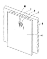
以下、本願発明に係る電気機器取り付け壁構造の実施形態について図面を参照して詳細に説明する。図1は本願発明の実施形態における壁下地施工工程を示す説明図である。図1において、構造用合板、石膏ボード等からなる壁下地材4は、躯体6に固定された胴縁5に釘、ビス等の固着手段により固着されている。ここで、壁下地材4には、予め、決められた位置付近に開口部41が穿たれ、壁下地材4の裏面に配線され、コネクター8が装着された電源コード7は上記開口部41を貫通して先行配線されている。また、上記電源コード7の他端は図外電源に接続されている。
Hereinafter, an embodiment of an electric equipment mounting wall structure according to the present invention will be described in detail with reference to the drawings. FIG. 1 is an explanatory view showing a wall foundation construction process in an embodiment of the present invention. In FIG. 1, a
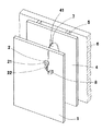
図2は上記先行配線された壁下地材4に化粧パネル1を施工するとともに、コネクター8が装着された電源コード7を貫通させる本願発明の第1実施形態に係る電気機器取り付け壁構造を示す分解説明図である。図2に示すように、例えば、MDF(中密度繊維板)に木目模様の印刷シートが貼着された化粧パネル1には壁下地材4に設けられた開口部41に対応する位置に鍵穴状係合保持部2が設けられている。
FIG. 2 is an exploded view showing an electric equipment mounting wall structure according to the first embodiment of the present invention in which the
上記鍵穴状係合保持部2はコネクター8が貫通する大径孔部21と上記電源コード7の径よりもやや大きな幅を有する小幅孔部22とから形成され、壁下地材4に先行配線された電源コード7は、化粧パネル1の裏面側から上記大径孔部21を通してコネクター8を貫通させ、化粧パネル1の表面側に電源コード7と共に配設される。その後、化粧パネル1を上記壁下地材4に釘、接着剤等の固着手段により固着する。このようにして、本願第1実施形態に係る電気機器取り付け壁構造を実施することができる。
The keyhole-shaped
すなわち、この電気機器取り付け壁構造は、表面側に電気機器9(図6参照)が取り付けられる化粧パネル1が壁下地材4に固定されてなる電気機器取り付け壁構造において、上記壁下地材4の表側には壁裏から導出される先端にコネクター8が装着された電源コード7が配設されており、上記化粧パネル1には表裏に貫通して上記コネクター8が所定の位置(大径孔部21の位置)においてのみ上記電源コード7と共に挿通される係合保持部(鍵穴状係合保持部2)を設けてなるものである。
That is, this electric equipment mounting wall structure is an electric equipment mounting wall structure in which the
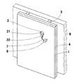
図3は、本願第1実施形態に係る電気機器取り付け壁構造を示す外観斜視図である。図3に示されているように、化粧パネル1の表面側にコネクター8付きの電源コード7が配設され、電源コード7が鍵穴状係合保持部2の小幅孔部22に係合、保持されている。
FIG. 3 is an external perspective view showing the electric equipment mounting wall structure according to the first embodiment of the present application. As shown in FIG. 3, a
図3に示すように、上記小幅孔部22に電源コード7はしっかりと係合され、この状態で電気機器を取り付ける工程との間に空白期間が生じても、その間に物理的に外部から力を加えて電源コード7を小幅孔部22から取り外さない限り、電源コード7はしっかりと係合、保持される。そして、電気機器取り付け工程に入るまで、電源コード7が壁下地材4の裏に落下する危険をなくすことができる。
As shown in FIG. 3, even if the
したがって、この電気機器取り付け壁構造においては、壁下地材4の表側には壁下地材4の裏(壁裏)から導出される先端にコネクター8が装着された電源コード7が配設されており、電源コード7は壁裏に隠蔽して配線されるので、見映えよく化粧パネル1の表面に電気機器9(図6参照)を取り付けることができる。
Therefore, in this electric equipment mounting wall structure, the
しかも、化粧パネル1には表裏に貫通してコネクター8が所定の位置(大径孔部21の位置)においてのみ電源コード7と共に挿通される係合保持部(鍵穴状係合保持部2)が設けられているので、コネクター8を所定の位置にして電源コード7と共に鍵穴状係合保持部2の大径孔部21に挿通させて化粧パネル1の表側に導出させることができ、その後には、コネクター8を所定の位置にしない限りコネクター8が鍵穴状係合保持部2の小幅孔部22に係止して、コネクター8及び電源コード7が壁裏へと落下してしまうことを防止することができ、電気工事等の施工をスムースに進めることができて電源コード7と電気機器9とを作業性よく接続することができる。
Moreover, the
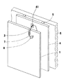
図4は、第1実施形態と同様に、壁下地施工工程を終了した後、化粧パネル1の上部端縁に電源コード7を係合する切り欠き係合保持部3を設けた本願発明の第2実施形態に係る電気機器取り付け壁構造を示す分解説明図である。図5は、本願発明の第2実施形態に係る電気機器取り付け壁構造を示す外観斜視図である。
FIG. 4 shows a second embodiment of the present invention in which a notch
すなわち、この電気機器取り付け壁構造において、係合保持部(切り欠き係合保持部3)はコネクター8が所定の向きにおいてのみ電源コード7と共に挿通されるものであり、化粧パネル1の上部端縁に上方へ開口した切り欠き状に形成されている。
That is, in this electric equipment mounting wall structure, the engagement holding portion (notched engagement holding portion 3) is such that the
図5に示されるように、上記切り欠き係合保持部3は幅wのスリットからなり、このスリットを通して、コネクター8が挿通し、係合、保持される。このとき、スリットの幅wは電源コード7への取付部のコネクター8の短辺aの長さよりも大きく、コネクター8の長辺bの長さより小さくされている。
As shown in FIG. 5, the notch
このようにして、コネクター8の短辺aを立てた状態で切り欠き係合保持部3を通して電源コード7を貫通させることにより、上記電源コード7は切り欠き係合保持部3にしっかりと係合される。そして、コネクター8を約直角に曲げておくことにより、万一コネクター8を壁下地材4の裏に引き込む力が働いても、コネクター8の長辺bがストッパーとして機能し、壁裏に落ち込むことを防げる。
In this way, the
したがって、この電気機器取り付け壁構造においては、係合保持部(切り欠き係合保持部3)が化粧パネル1の上部端縁に上方へ開口した切り欠き状に形成されているため、電源コード7を切り欠き係合保持部3に上方から容易に係止させることができ、その後、化粧パネル1が壁下地材4に固定された状態では、コネクター8を所定の向きにしない限りコネクター8が切り欠き係合保持部3に係止するので、コネクター8及び電源コード7が壁裏へと落下してしまうことを防止することができる。
Therefore, in this electric equipment mounting wall structure, the engagement holding part (notch engagement holding part 3) is formed in a cutout shape opened upward at the upper edge of the
また、上記コネクター8と図外電気機器の電源コネクターとを接続した後、上記鍵穴状係合保持部2の大径孔部21、あるいは、切り欠き係合保持部3のスリットから、上記コネクター8を接続状態で意図的に壁裏に落とし込むことにより、電気機器内にコネクター8を収容するスペースを設ける必要がなく、電気機器の設計の自由度を高めることができる。
Further, after the
図6は本願発明に係る電気機器取り付け壁構造を用いて化粧パネル1の表面に電気機器9としての照明器具を取り付けた状態を示す外観斜視図である。図6に示されているように、化粧パネル1の表面に配線類は見えず隠蔽配線とされ、見映えよく照明器具を取り付けることができる。
FIG. 6 is an external perspective view showing a state in which a lighting fixture as the
なお、上記実施形態においては、化粧パネル1の表面にコネクター8付きの電源コード7を配設する例について述べたが、化粧パネル1として、温水パイプや面状電気ヒーター等が内部に設けられた暖房用化粧パネルを用い、その表面に電源コード7を配設してもよい。このように本願発明に係る電気機器取り付け壁構造は設計変更自在であり、特許請求の範囲を逸脱しない限り、いずれの場合も本願発明の技術的範囲に属する。
In the above embodiment, an example in which the
1 化粧パネル
2 鍵穴状係合保持部
21 大径孔部
22 小幅孔部
3 切り欠き係合保持部
4 壁下地材
41 開口部
5 胴縁
6 躯体
7 電源コード
8 コネクター
a コネクターの短辺
b コネクターの長辺
9 電気機器
DESCRIPTION OF
Claims (2)
Priority Applications (1)
| Application Number | Priority Date | Filing Date | Title |
|---|---|---|---|
| JP2008245961A JP5217839B2 (en) | 2008-09-25 | 2008-09-25 | Wall mounting structure for electrical equipment |
Applications Claiming Priority (1)
| Application Number | Priority Date | Filing Date | Title |
|---|---|---|---|
| JP2008245961A JP5217839B2 (en) | 2008-09-25 | 2008-09-25 | Wall mounting structure for electrical equipment |
Publications (2)
| Publication Number | Publication Date |
|---|---|
| JP2010077643A true JP2010077643A (en) | 2010-04-08 |
| JP5217839B2 JP5217839B2 (en) | 2013-06-19 |
Family
ID=42208365
Family Applications (1)
| Application Number | Title | Priority Date | Filing Date |
|---|---|---|---|
| JP2008245961A Expired - Fee Related JP5217839B2 (en) | 2008-09-25 | 2008-09-25 | Wall mounting structure for electrical equipment |
Country Status (1)
| Country | Link |
|---|---|
| JP (1) | JP5217839B2 (en) |
Citations (4)
| Publication number | Priority date | Publication date | Assignee | Title |
|---|---|---|---|---|
| JPH05287874A (en) * | 1992-04-06 | 1993-11-02 | Natl House Ind Co Ltd | Wall structure |
| JP2000291179A (en) * | 1999-04-01 | 2000-10-17 | National House Industrial Co Ltd | External wall panel |
| JP2002112426A (en) * | 2000-09-29 | 2002-04-12 | National House Industrial Co Ltd | Tatami gap filling and wiring structure using the same |
| JP2004201782A (en) * | 2002-12-24 | 2004-07-22 | Daiichi Shokai Co Ltd | Gaming machine |
-
2008
- 2008-09-25 JP JP2008245961A patent/JP5217839B2/en not_active Expired - Fee Related
Patent Citations (4)
| Publication number | Priority date | Publication date | Assignee | Title |
|---|---|---|---|---|
| JPH05287874A (en) * | 1992-04-06 | 1993-11-02 | Natl House Ind Co Ltd | Wall structure |
| JP2000291179A (en) * | 1999-04-01 | 2000-10-17 | National House Industrial Co Ltd | External wall panel |
| JP2002112426A (en) * | 2000-09-29 | 2002-04-12 | National House Industrial Co Ltd | Tatami gap filling and wiring structure using the same |
| JP2004201782A (en) * | 2002-12-24 | 2004-07-22 | Daiichi Shokai Co Ltd | Gaming machine |
Also Published As
| Publication number | Publication date |
|---|---|
| JP5217839B2 (en) | 2013-06-19 |
Similar Documents
| Publication | Publication Date | Title |
|---|---|---|
| US8209921B2 (en) | Flush mount panels with multiple aligned receiving brackets | |
| US7621096B2 (en) | Construction blocking bracket | |
| CN109155171B (en) | Apparatus, system and method for mounting electrical equipment of a building wall structure | |
| CN110088413B (en) | Panel, mounting fixture and wall covering or ceiling covering for three-dimensional patterns of wall panels and ceiling panels | |
| US7461483B2 (en) | Devices and methods for flangeless installations | |
| CN102472045B (en) | Structural panel or set of structural panels, fastening system for structural panels and method for fastening structural panels | |
| JP5217839B2 (en) | Wall mounting structure for electrical equipment | |
| US20090107083A1 (en) | Multicategory Collection of Ceiling/Wall Devices With Familial Appearances | |
| JP5901695B2 (en) | How to assemble and install wall-mounted storage furniture | |
| US20110067320A1 (en) | Wall-Mount Adjustment Systems And Methods | |
| JP5271130B2 (en) | Exterior wall structure | |
| JP5558302B2 (en) | Wall material unit construction structure and construction method | |
| JP3387844B2 (en) | Structure for storing timber and flooring | |
| JP7637543B2 (en) | Wiring cover | |
| US7699138B2 (en) | Devices and methods for flangeless installations | |
| JP2005097925A (en) | Building structure with wiring function | |
| JP3121632U (en) | Building equipment inspection port | |
| KR102575929B1 (en) | The wall mounted cable tie | |
| JP3935484B2 (en) | Gas stopper mounting bracket | |
| JP5366321B2 (en) | cabinet | |
| JP5595741B2 (en) | Electrical equipment storage structure in wall | |
| JP2008271429A (en) | Interior decoration panel for sound output with sound generating function | |
| JP2025105194A (en) | Kitchen unit | |
| JP4617087B2 (en) | Skirting construction method | |
| CN112020591B (en) | Mounting structure of decorative board |
Legal Events
| Date | Code | Title | Description |
|---|---|---|---|
| A621 | Written request for application examination |
Free format text: JAPANESE INTERMEDIATE CODE: A621 Effective date: 20101122 |
|
| A711 | Notification of change in applicant |
Free format text: JAPANESE INTERMEDIATE CODE: A712 Effective date: 20120111 |
|
| A977 | Report on retrieval |
Free format text: JAPANESE INTERMEDIATE CODE: A971007 Effective date: 20120516 |
|
| A131 | Notification of reasons for refusal |
Free format text: JAPANESE INTERMEDIATE CODE: A131 Effective date: 20120522 |
|
| A521 | Written amendment |
Free format text: JAPANESE INTERMEDIATE CODE: A523 Effective date: 20120627 |
|
| RD01 | Notification of change of attorney |
Free format text: JAPANESE INTERMEDIATE CODE: A7421 Effective date: 20121214 |
|
| TRDD | Decision of grant or rejection written | ||
| A01 | Written decision to grant a patent or to grant a registration (utility model) |
Free format text: JAPANESE INTERMEDIATE CODE: A01 Effective date: 20130205 |
|
| A61 | First payment of annual fees (during grant procedure) |
Free format text: JAPANESE INTERMEDIATE CODE: A61 Effective date: 20130218 |
|
| FPAY | Renewal fee payment (event date is renewal date of database) |
Free format text: PAYMENT UNTIL: 20160315 Year of fee payment: 3 |
|
| FPAY | Renewal fee payment (event date is renewal date of database) |
Free format text: PAYMENT UNTIL: 20160315 Year of fee payment: 3 |
|
| LAPS | Cancellation because of no payment of annual fees |