JP2010077704A - Remote operation structure of drain plug - Google Patents
Remote operation structure of drain plug Download PDFInfo
- Publication number
- JP2010077704A JP2010077704A JP2008247992A JP2008247992A JP2010077704A JP 2010077704 A JP2010077704 A JP 2010077704A JP 2008247992 A JP2008247992 A JP 2008247992A JP 2008247992 A JP2008247992 A JP 2008247992A JP 2010077704 A JP2010077704 A JP 2010077704A
- Authority
- JP
- Japan
- Prior art keywords
- transmission member
- overflow
- pop
- drain
- manual operation
- Prior art date
- Legal status (The legal status is an assumption and is not a legal conclusion. Google has not performed a legal analysis and makes no representation as to the accuracy of the status listed.)
- Granted
Links
- 230000005540 biological transmission Effects 0.000 claims abstract description 32
- 230000002093 peripheral effect Effects 0.000 description 7
- XLYOFNOQVPJJNP-UHFFFAOYSA-N water Substances O XLYOFNOQVPJJNP-UHFFFAOYSA-N 0.000 description 4
- 101150114468 TUB1 gene Proteins 0.000 description 1
- 238000013459 approach Methods 0.000 description 1
- 238000005452 bending Methods 0.000 description 1
- 230000000994 depressogenic effect Effects 0.000 description 1
Images






Landscapes
- Sink And Installation For Waste Water (AREA)
Abstract
Description
本発明は、排水栓遠隔操作構造体に係り、より詳しくは、洗面台(洗面ボール)や浴槽の排水栓(弁)を遠隔操作する構造体に関する。 The present invention relates to a drain plug remote control structure, and more particularly to a structure that remotely controls a wash basin (wash bowl) and a drain plug (valve) of a bathtub.
従来、上述の排水栓遠隔操作構造体としては、図14, 図15に例示するように、洗面ボールや浴槽等の貯水槽41の側壁42の中間高さ乃至上端近傍にオーバーフロー用排水口43を手前(水平)方向に開設して、手動操作部材44を矢印H方向に手動操作し、この矢印H方向の作動を、ワイヤ等のポップアップ伝達部材45を介して、貯水槽41の底壁46の排水栓47に伝達するように連繋して、開閉作動していた。
しかも、図14, 図15からも明らかなように、オーバーフロー配管48内に上記ポップアップ伝達部材45を挿入して、手動操作部材44と排水栓47とを、連繋するものが知られている(特許文献1参照)。
Moreover, as is apparent from FIGS. 14 and 15, there is known one in which the pop-up
上述の従来の排水栓遠隔操作構造体は、小さな曲率半径R0 でポップアップ伝達部材(レリースワイヤ)を屈曲させるので、この屈曲部49にて折損したり、大きな摩擦抵抗を生じて作動が困難になる等の故障を発生する虞があった。
さらに、オーバーフロー用排水口43が、直接的に人の目に見えて、見苦しく、意匠性も悪い等の問題があった。
Since the above-described conventional drain plug remote control structure bends the pop-up transmission member (release wire) with a small curvature radius R 0, it breaks at the
Furthermore, the
そこで、本発明は、オーバーフロー用排水口にポップアップ伝達部材の上端部を上下ストレート状に配設し、上記オーバーフロー用排水口を包囲する隠しカバーに該上端部を連結して、該隠しカバーを手動操作部材に兼用したものである。
また、オーバーフロー配管内にポップアップ伝達部材を挿入し、該伝達部材の上端部を上下ストレート状としつつオーバーフロー用排水口に配設し、該オーバーフロー用排水口を包囲する隠しカバーに該上端部を連結して、該隠しカバーを手動操作部材に兼用したものである。
In view of this, the present invention provides an upper end of the pop-up transmission member in an upper and lower straight shape at the overflow drain, and connects the upper end to a cover that surrounds the overflow drain to manually remove the cover. It is also used as an operation member.
In addition, a pop-up transmission member is inserted into the overflow pipe, and the upper end portion of the transmission member is disposed in the overflow drainage port while being straight up and down, and the upper end portion is connected to a hidden cover surrounding the overflow drainage port. The hidden cover is also used as a manual operation member.
本発明に係る排水栓遠隔操作構造体によれば、手動操作部材がオーバーフロー用排水口を覆うように隠すことができ、人の目に直接的にオーバーフロー用排水口が見えず、意匠性が向上でき、気持ち良く洗面ボールや浴槽等の使用ができる。
また、ポップアップ伝達部材の上端部は直線状態として、無理な曲げ力が作用せず、スムースに力の伝達が行われると共に、伝達部材の損傷を防止し、耐久性が向上する。さらに、装置の施工性及び信頼性が向上できる。
According to the drain valve remote control structure according to the present invention, the manual operation member can be hidden so as to cover the overflow drain port, and the overflow drain port is not directly visible to human eyes, improving the design. Can be used comfortably, such as a wash-basin or bathtub.
Further, the upper end portion of the pop-up transmission member is in a straight state, so that an excessive bending force does not act, force is transmitted smoothly, damage to the transmission member is prevented, and durability is improved. Furthermore, the workability and reliability of the apparatus can be improved.
以下、図示の実施の形態に基づき本発明を詳説する。
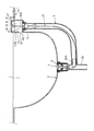
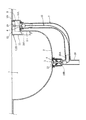
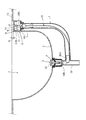
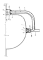
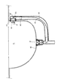
図1〜図5に示す第1の実施の形態、図6〜図11に示す第2の実施の形態、及び、図12〜図13に示す第3の実施の形態につき、共通した基本的構成から、まず説明すれば、1は、水を貯溜可能な槽であって、洗面ボールを例示し、この槽1の底壁2には排水口4が開設されて、これに排水栓3が開閉可能に付設されている。そして、槽1の側壁5の上端近傍には、オーバーフロー用排水口6が上方向に開設されている。このとき、槽1が洗面ボールの場合は、後方の側壁5にオーバーフロー用排水口6が配設されることとなる。
Hereinafter, the present invention will be described in detail based on the illustrated embodiment.
Basic configuration common to the first embodiment shown in FIGS. 1 to 5, the second embodiment shown in FIGS. 6 to 11 and the third embodiment shown in FIGS. First, a
10はポップアップ伝達部材であり、その上端部10Aは、オーバーフロー用排水口6に上下ストレート状に配設される。
7はオーバーフロー配管であり、上記伝達部材10は、このオーバーフロー配管7に挿入されている。上記底壁2の排水口4は、図外の下水管に連通する排水管20に連通連結されているが、この排水管20をT字型に分岐して、この分岐部20Aに於て、上記オーバーフロー配管7が接続される。
ポップアップ伝達部材10は、この分岐部20Aにて弯曲して、約90°方向変換し、その端部10Bは、排水栓3の傘状弁体12に連結される。
The pop-up
そして、槽1の側壁5の上端縁と、上周面1Aとの角部1Bを、例えば、直方体形状に切欠いて凹窪部8を形成し、この凹窪部8の底面8Aに、オーバーフロー用排水口6を上方向に開口するように配設する。Cは、この上方開口状のオーバーフロー用排水口6を、上方及び前方から包囲する隠しカバーであり、この隠しカバーCは、その裏面を、伝達部材10の上端部10Aに連結し、手動にてポップアップ伝達部材10を操作させるための手動操作部材9に兼用する。
And the corner |
図1〜図5に示した第1の実施の形態では、底壁2の排水栓3が開の状態───以下、開栓時という───にあっては、隠しカバーC(手動操作部材9)の天井壁部14の上面13は、槽1の周壁の上周面1Aと段差が無くなって、同一平面状態を保っている(図1と図3参照)。具体的には、隠しカバーC(手動操作部材9)の形状は、矩形状の天井壁部14と、この天井壁部14の4辺から垂設された前壁部15,左右側壁部16, 16,後壁部17とを、有し、前壁部15の上下寸法を十分に大きくなるように設定し、図1と図3に示す開栓時では、凹窪部8の略全体を隠して、凹窪部8の底面8Aの前端縁と、前壁部15の下端縁との間には、微小ギャップGが形成され、乃至、軽く相互に接触する。
In the first embodiment shown in FIG. 1 to FIG. 5, when the
次に、底壁2の排水栓3が閉の状態───以下、閉栓時という───にあっては、図2と図4に示すように、隠しカバーC(手動操作部材9)の天井壁部14の上面13は、槽1の周壁の上周面1Aよりも所定ストローク分の段差寸法Aだけ上方位置にあり、この段差寸法Aは、左右側壁部16, 16及び後壁部17の高さ寸法よりも小さい。即ち、左右側壁部16, 16及び後壁部17の高さ寸法を、段差寸法Aよりも小さく設定し、これによって、左右側壁部16と後壁部17は、常時、凹窪部8の内部を隠している。
Next, when the drain plug 3 on the
そして、この閉栓時では、図2と図4に示す如く、前壁部15の下端縁と、凹窪部8の底面8Aとの間に、オーバーフロー用窓部18が形成される。
なお、天井壁部14の裏面中央部には、孔付ボス部19を垂設して、その孔に、伝達部材10の上端を挿入して固着している。
At the time of closing, an
It should be noted that a
次に、図12と図13に示した第3の実施の形態では、上述の第1の実施の形態と以下の点で相違する。即ち、図13に示す閉栓時に段差が無くなり、図12に示す開栓時に段差Eが生ずる。具体的に説明すれば、開栓時(図12)には、手動操作部材9(隠しカバーC)の上面13が、槽1の上周面1Aよりも、段差E分だけ沈み込んだ下降状態にあり、このとき、微小ギャップGが前壁部15の下端縁と、凹窪部8の底面8Aとの間に形成され、又は、軽く接触している。そして、閉栓時(図13)には、手動操作部材9(隠しカバーC)の上面13が、槽1の上周面1Aと同一平面状となると共に、オーバーフロー用窓部18が形成される。
Next, the third embodiment shown in FIG. 12 and FIG. 13 differs from the first embodiment described above in the following points. That is, the step is eliminated when the plug shown in FIG. 13 is closed, and the step E occurs when the plug shown in FIG. 12 is opened. More specifically, when opened (FIG. 12), the
ところで、図1〜図5の第1の実施の形態、及び、図12〜図13の第3の実施の形態では、手動操作部材9の前壁部15と、側壁5の上端面とは、同一鉛直面状を形成するように、前壁部15の前後方向位置が設定され、開栓時にあって、微小ギャップGをもって、前壁部15の下端縁が底面8Aに接近し、又は、軽く接触して、意匠性も優れている。
By the way, in 1st Embodiment of FIGS. 1-5, and 3rd Embodiment of FIGS. 12-13, the
これに対し、図6〜図10に示した第2の実施の形態では、開栓時(図6)及び閉栓時(図7)のいずれに於ても、(図示省略のスプリングを、伝達部材10の途中に介在させることにより、)手動操作部材9は段差の無い高さに位置する構成としている。つまり、手動操作部材9の上面13は、槽1の上周面1Aと同一平面状を保持し、段差が生じない。但し、前壁部15が、所定寸法Fだけ側壁5よりも前方(手前)に張り出すように、下方開口状のオーバーフロー間隔部18Aを形成している。
図8及び図10に示すように、所定段差E分だけ手動操作部材9(隠しカバーC)が下降するのは、使用者が上面13を押下げる力を加えた押し込み状態の時のみである。
On the other hand, in the second embodiment shown in FIGS. 6 to 10, the spring (not shown) is connected to the transmission member both when opening (FIG. 6) and when closing (FIG. 7). 10), the
As shown in FIGS. 8 and 10, the manual operation member 9 (hidden cover C) is lowered by a predetermined step E only when the user is in a pushing state in which a force for pushing down the
なお、上述の図示の実施の形態では、槽1が洗面ボールの場合を示したが、これ以外に浴槽や他の洗面台等であっても自由である。あるいは、伝達部材10を、オーバーフロー配管7の外部に配設するのにも、適用可能である。
In the illustrated embodiment described above, the case where the
本発明は、上述のように、オーバーフロー用排水口6にポップアップ伝達部材10の上端部10Aを上下ストレート状に配設し、上記オーバーフロー用排水口6を包囲する隠しカバーCに該上端部10Aを連結して、該隠しカバーCを手動操作部材9に兼用した構成であるので、ポップアップ伝達部材10の上端部10Aが小さな曲率半径R0 をもって、(図14,図15のように、)弯曲した場合の折損事故を防止でき、かつ、ワイヤー等から成る伝達部材10の摩擦抵抗の増加も防ぐことができて、スムースな排水栓開閉を行い得る。さらに、オーバーフロー用排水口6が人の目に見えずに、美しく隠すことが可能であり、意匠性も著しく改善できる。
In the present invention, as described above, the
また、オーバーフロー配管7内にポップアップ伝達部材10を挿入し、該伝達部材10の上端部10Aを上下ストレート状としつつオーバーフロー用排水口6に配設し、該オーバーフロー用排水口6を包囲する隠しカバーCに該上端部10Aを連結して、該隠しカバーCを手動操作部材9に兼用した構成であるので、伝達部材10をオーバーフロー配管7内に挿入して組立て易くなり、装置の施工性と信頼性が改善できる。また、水密的な接続を行う箇所が減少し、漏水の虞が無くなり、下方のキャビネット内等に伝達部材10が露出しないで済む。そして、ポップアップ伝達部材10の上端部10Aが小さな曲率半径R0 をもって、(図14,図15のように、)弯曲した場合の折損事故を防止でき、かつ、ワイヤー等から成る伝達部材10の摩擦抵抗の増加も防ぐことができて、スムースな排水栓開閉を行い得る。さらに、オーバーフロー用排水口6が人の目に見えずに、美しく隠すことが可能であり、意匠性も著しく改善できる。
Also, a pop-
6 オーバーフロー用排水口
7 オーバーフロー配管
9 手動操作部材
10 ポップアップ伝達部材
10A 上端部
C 隠しカバー
6
10 Pop-up transmission member
10A Top end C Hidden cover
Claims (2)
Priority Applications (1)
| Application Number | Priority Date | Filing Date | Title |
|---|---|---|---|
| JP2008247992A JP5493068B2 (en) | 2008-09-26 | 2008-09-26 | Drain tap remote control structure |
Applications Claiming Priority (1)
| Application Number | Priority Date | Filing Date | Title |
|---|---|---|---|
| JP2008247992A JP5493068B2 (en) | 2008-09-26 | 2008-09-26 | Drain tap remote control structure |
Publications (2)
| Publication Number | Publication Date |
|---|---|
| JP2010077704A true JP2010077704A (en) | 2010-04-08 |
| JP5493068B2 JP5493068B2 (en) | 2014-05-14 |
Family
ID=42208425
Family Applications (1)
| Application Number | Title | Priority Date | Filing Date |
|---|---|---|---|
| JP2008247992A Expired - Fee Related JP5493068B2 (en) | 2008-09-26 | 2008-09-26 | Drain tap remote control structure |
Country Status (1)
| Country | Link |
|---|---|
| JP (1) | JP5493068B2 (en) |
Cited By (3)
| Publication number | Priority date | Publication date | Assignee | Title |
|---|---|---|---|---|
| JP2012036708A (en) * | 2010-08-04 | 2012-02-23 | Nippon Alpha:Kk | Operation side structure of remote control type drain valve device |
| JP2012140794A (en) * | 2010-12-28 | 2012-07-26 | Maruichi Corp | Remote control type drain plug device |
| JP2019119995A (en) * | 2017-12-28 | 2019-07-22 | 丸一株式会社 | Drain plug device |
Citations (3)
| Publication number | Priority date | Publication date | Assignee | Title |
|---|---|---|---|---|
| JPS55163367U (en) * | 1979-05-11 | 1980-11-22 | ||
| JPH04357222A (en) * | 1986-07-14 | 1992-12-10 | Kohler Co | Device for regulating drain valve for bathtub |
| JPH10165323A (en) * | 1996-12-06 | 1998-06-23 | Maruichi Kk | Drain plug opening/closing device of remote control type |
-
2008
- 2008-09-26 JP JP2008247992A patent/JP5493068B2/en not_active Expired - Fee Related
Patent Citations (3)
| Publication number | Priority date | Publication date | Assignee | Title |
|---|---|---|---|---|
| JPS55163367U (en) * | 1979-05-11 | 1980-11-22 | ||
| JPH04357222A (en) * | 1986-07-14 | 1992-12-10 | Kohler Co | Device for regulating drain valve for bathtub |
| JPH10165323A (en) * | 1996-12-06 | 1998-06-23 | Maruichi Kk | Drain plug opening/closing device of remote control type |
Cited By (4)
| Publication number | Priority date | Publication date | Assignee | Title |
|---|---|---|---|---|
| JP2012036708A (en) * | 2010-08-04 | 2012-02-23 | Nippon Alpha:Kk | Operation side structure of remote control type drain valve device |
| JP2012140794A (en) * | 2010-12-28 | 2012-07-26 | Maruichi Corp | Remote control type drain plug device |
| JP2019119995A (en) * | 2017-12-28 | 2019-07-22 | 丸一株式会社 | Drain plug device |
| JP7266231B2 (en) | 2017-12-28 | 2023-04-28 | 丸一株式会社 | drain plug device |
Also Published As
| Publication number | Publication date |
|---|---|
| JP5493068B2 (en) | 2014-05-14 |
Similar Documents
| Publication | Publication Date | Title |
|---|---|---|
| JP5593764B2 (en) | Wall faucet | |
| JP6764563B2 (en) | Flush toilet device | |
| JP5493068B2 (en) | Drain tap remote control structure | |
| JP4922116B2 (en) | Wash basin | |
| JP5027538B2 (en) | Bathroom vanity | |
| JP6819022B2 (en) | Flush toilet device | |
| KR880001893A (en) | Bath Drain Control Valves and Outflow Plates | |
| JP2019052422A (en) | Washbowl | |
| EP3561187A3 (en) | Lavatory with hidden drain | |
| JP2017133333A (en) | Remote control type drain plug device | |
| JP2010031570A (en) | Drainage connection structure of flush toilet bowl and washbasin | |
| CN204370530U (en) | A kind of seamless toilet cistern | |
| KR100664368B1 (en) | Wall Recessed Outlet Safety Cover for Apartment | |
| JP4456961B2 (en) | Eye plate member used in bathtub piping structure | |
| JP5293048B2 (en) | Washbasin | |
| JP2006057339A (en) | Pop-up draining mechanism | |
| JP4840008B2 (en) | Bathroom piping structure | |
| JP5081185B2 (en) | Built-in hand-washing machine | |
| JP2020033752A (en) | Drain plug device | |
| JP2006070539A (en) | Piping decorative cover | |
| JP6858728B2 (en) | Water supply device for washing tank | |
| JP2637808B2 (en) | How to arrange sanitary equipment in a unit bathroom | |
| JP6293607B2 (en) | Mirror cabinet and wash basin | |
| JP6991651B2 (en) | Remote control device | |
| JP2006063518A (en) | Washstand |
Legal Events
| Date | Code | Title | Description |
|---|---|---|---|
| A621 | Written request for application examination |
Free format text: JAPANESE INTERMEDIATE CODE: A621 Effective date: 20110816 |
|
| A977 | Report on retrieval |
Free format text: JAPANESE INTERMEDIATE CODE: A971007 Effective date: 20121101 |
|
| A131 | Notification of reasons for refusal |
Free format text: JAPANESE INTERMEDIATE CODE: A131 Effective date: 20130521 |
|
| A521 | Request for written amendment filed |
Free format text: JAPANESE INTERMEDIATE CODE: A523 Effective date: 20130628 |
|
| TRDD | Decision of grant or rejection written | ||
| A01 | Written decision to grant a patent or to grant a registration (utility model) |
Free format text: JAPANESE INTERMEDIATE CODE: A01 Effective date: 20131224 |
|
| A61 | First payment of annual fees (during grant procedure) |
Free format text: JAPANESE INTERMEDIATE CODE: A61 Effective date: 20140116 |
|
| R150 | Certificate of patent or registration of utility model |
Ref document number: 5493068 Country of ref document: JP Free format text: JAPANESE INTERMEDIATE CODE: R150 |
|
| R250 | Receipt of annual fees |
Free format text: JAPANESE INTERMEDIATE CODE: R250 |
|
| R250 | Receipt of annual fees |
Free format text: JAPANESE INTERMEDIATE CODE: R250 |
|
| LAPS | Cancellation because of no payment of annual fees |