JP2010077793A - Corner part joint cover - Google Patents
Corner part joint cover Download PDFInfo
- Publication number
- JP2010077793A JP2010077793A JP2009039956A JP2009039956A JP2010077793A JP 2010077793 A JP2010077793 A JP 2010077793A JP 2009039956 A JP2009039956 A JP 2009039956A JP 2009039956 A JP2009039956 A JP 2009039956A JP 2010077793 A JP2010077793 A JP 2010077793A
- Authority
- JP
- Japan
- Prior art keywords
- joint cover
- corner
- floor
- building
- joint
- Prior art date
- Legal status (The legal status is an assumption and is not a legal conclusion. Google has not performed a legal analysis and makes no representation as to the accuracy of the status listed.)
- Pending
Links
Images


Landscapes
- Building Environments (AREA)
Abstract
Description
本発明は、建築物の床とその周囲の地盤との間に形成された目地のコーナー部における上面を覆うコーナー部目地カバーに関するものである。 The present invention relates to a corner joint cover that covers an upper surface of a corner portion of a joint formed between a floor of a building and the surrounding ground.
従来、建築物の床とその周囲の地盤との間に形成された目地の上面を覆う目地カバーとして、例えば特許文献1に開示されているような構造のものが存在する。
Conventionally, as a joint cover that covers the upper surface of the joint formed between the floor of the building and the surrounding ground, there is a structure as disclosed in
上記特許文献1に開示されているような目地カバーは、直線状の目地の上面を覆うものであり、目地の平面視コーナー部の上面には、このような目地カバーは設けられず、目地のコーナー部上に例えば大型の車が乗ったような場合には、この目地のコーナー部上面を覆う部材が破損してしまうという問題点があった。
The joint cover as disclosed in
本発明は、大型車が乗っても破損することのないコーナー部目地カバーの提供を目的とし、この目的の少なくとも一部を達成するために以下の手段を採った。
本発明のコーナー部目地カバーは、建築物の床とその周囲の地盤との間に形成された目地の平面視コーナー部の上面を覆うコーナー部目地カバーであって、該コーナー部目地カバーは、構造材として鉄製無垢板が用いられていることである。
The object of the present invention is to provide a corner joint cover that does not break even when a large vehicle rides, and the following measures are taken in order to achieve at least a part of this object.
The corner joint cover of the present invention is a corner joint cover that covers an upper surface of a corner portion in plan view formed between the floor of the building and the surrounding ground, and the corner joint cover is This is because solid steel plates are used as the structural material.
本発明のコーナー部目地カバーは、構造材として鉄製無垢板が用いられているため、強度が極めて大であり、大型車の重量に耐えることができ、破損することがない。 The corner joint cover of the present invention uses a solid steel plate as a structural material, and therefore has a very high strength, can withstand the weight of a large vehicle, and is not damaged.
また、本発明のコーナー部目地カバーにおいて、表面側の表面プレートと底面側のグレーチングとの間に鉄製無垢板が挟み込まれた縦断面構造に形成されているものとすることもできる。
こうすれば、強度が極めて大であり、このコーナー部目地カバー上に大型車が乗った場合にも、大型車の重量に耐えることができ、破損することがない。
Further, the corner joint cover according to the present invention may be formed in a vertical cross-sectional structure in which a solid iron plate is sandwiched between a front surface plate and a bottom surface grating.
In this way, the strength is extremely high, and even when a large vehicle rides on the corner joint cover, it can withstand the weight of the large vehicle and will not be damaged.
また、本発明のコーナー部目地カバーにおいて、鉄製無垢板の厚みは9mm以上であるものとすることもできる。
こうすれば、コーナー部目地カバーに十分な強度が確保されて、大型車等が上面に乗った際にも変形,破損が生ずることがない。
In the corner joint joint cover of the present invention, the thickness of the solid iron plate may be 9 mm or more.
In this way, sufficient strength is ensured for the corner joint cover, and deformation or breakage does not occur when a large vehicle or the like rides on the upper surface.
次に、本発明を実施するための形態を実施例を用いて説明する。
図1は、目地とそのコーナー部の上面に覆設されるコーナー部目地カバーの概略縦断面を示すものであり、建築物の床1の周囲に形成された人工の地盤2は、目地3を介して隣接しており、建築物の床1側は、図示を省略しているが、緩衝機能を備えた免震装置によって支持されて免震構造となっている。
目地3は、建築物の床1の周囲に沿って所定幅で形成され、地震時における建築物の床1と周囲の地盤2との水平方向の相対的な揺れを吸収できるように設けられたものであり、目地3の底側は通水溝路3aとなっており、上方から目地3内に流入した雨水等を、通水溝路3aを通して排水できるように構成されている。なお、図1中3bは、内側壁である。
Next, the form for implementing this invention is demonstrated using an Example.
FIG. 1 shows a schematic vertical section of a corner joint cover covered on the upper surface of the joint and its corner portion. The
The
目地3上に覆設されるコーナー部目地カバー4Aは、地震時に建築物の床1と地盤2が水平方向の揺れにより近づいた場合には、図1の想像線で示すように、自由端側、即ち地盤2側が上方へ持ち上がって、地盤2上に乗るように構成されており、目地3の間隔が元に戻った時には、自動的に自由端側が地盤2と面一の状態に戻されるように構成されている。
即ち、コーナー部目地カバー4Aの建築物の床1側は揺動可能な構造となっており、地盤2側が上下動できる自由端となっている。
The
That is, the
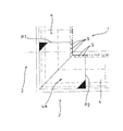
本例のコーナー部目地カバー4Aは、図3の平面概略構成図で示すように、目地3が直交するコーナー部の図3中P1〜P2間のコーナー部を覆設できるものである。なお、このコーナー部目地カバー4AのP1側およびP2側には、通常のグレーチングで構成される目地カバー4,4がそれぞれ目地3上に覆設される。
従来では、この目地3のコーナー部にはグレーチングがなく、弱いものであり、このコーナー部上に大型車が乗った場合は、コーナー部が破損しやすいものであった。そこで、この目地のコーナー部には、図2の縦断面構成図で示すような構造のコーナー部目地カバー4Aが覆設される。
As shown in the schematic plan view of FIG. 3, the
Conventionally, the corner portion of the
コーナー部目地カバー4Aは、図2に示すように、表面側の表面プレート5と、底面側のグレーチング7との間に、鉄製の鉄無垢板6が挟み込まれた縦断面構造に形成されている。
表面プレート5は、例えば厚さが6mm程度であり、その下の鉄無垢板6は厚みが45mm程度であり、その下のグレーチング7は厚さが44mm程度に設定されている。
鉄無垢板6には、上下に貫通状に複数のボルト孔6a,6a,6aが形成されており、この各ボルト孔6a内に、表面プレート5側からボルト10がグレーチング7の上面側に差し込まれて、下側からボルト10,10,10にナットを締め付けて、表面プレート5とグレーチング7間に鉄無垢板6が挟み込まれている。
As shown in FIG. 2, the
The
A plurality of
なお、グレーチング7は、グレーチングとして一般に用いられる構造のものであり、メインバーとクロスバーとを格子状に配設して構成されたものである。
なお、鉄無垢板6およびグレーチング7の水平方向長さは、ほぼ同一の長さに設定されており、建築物の床1側から地盤2側に掛け渡すことのできる長さ寸法に設定されている。
なお、表面プレート5は、更に地盤2側の先端に水平に延びる覆蓋板部5aが形成されている。
The grating 7 has a structure generally used as a grating, and is configured by arranging a main bar and a cross bar in a lattice shape.
In addition, the horizontal direction length of the
The
建築物の床1側には段部が形成され、この段部には断面略L字状の受け枠12が設けられており、この受け枠12を貫通して、例えばM20の六角ボルト11がその下端側を建築物の床1内に埋設された状態で上端側が段部に立設されている。
この六角ボルト11は、図3に示すように、コーナー部目地カバー4Aの建築物の床1側に所定間隔で設けられたキャップ9,9,9のそれぞれの下側に配置されて、それぞれその下端側が建築物の床1に埋設固定されている。
A step portion is formed on the
As shown in FIG. 3, the
六角ボルト11は、受け枠12の底側に溶接固定されたナット14にねじ込まれて、その下端の頭部が埋設されており、さらに六角ボルト11には、ナット14の下側から緩み止め用のナット15が締め付けられており、この溶接ナット14および緩み止めナット15も建築物の床1に埋設された状態となっている。
建築物の床1にはアンカー13,13が埋設されており、このアンカー13,13により受け枠12および六角ボルト11が強固に固定支持されている。
The
受け枠12の上面には、座金16と、その上面にクッション17が設けられ、この座金16,クッション17を貫通して六角ボルト11の上端側が起立しており、この起立した六角ボルト11の外周には、コイル状のバネ18が配設され、コイル状のバネ18の上面側には座金を介在させて六角ボルト11にナット19が締め付けられている。
六角ボルト11の上端側はグレーチング7の建築物の床1側に連結されており、これにより、コーナー部目地カバー4Aの建築物の床1側はバネ18を介して上下方向に揺動できる構造となっている。
A
The upper end side of the
一方、地盤2側にも段部が形成され、この段部上には載置材20が設けられ、載置材20の目地3側には受け枠20aが設けられており、この受け枠20aと反対側には上傾状の傾斜受け枠20bが設けられている。この受け枠20aおよび傾斜受け枠20b上にクッション21,21を介在させて、コーナー部目地カバー4Aの自由端側が載置されるものである。
なお、コーナー部目地カバー4Aの鉄無垢板6およびグレーチング7の自由端の先端側には、傾斜面を有する傾斜部材8が覆蓋板部5aの底側に取り付けられている。この傾斜部材8は傾斜受け枠20bに対応した上傾状の傾斜面を有するものである。
On the other hand, a step portion is also formed on the
An
前述した如く、地震時における建築物の床1と地盤2との水平方向の相対的な揺れが生じた時には、目地3で揺れが吸収されるが、目地3の水平幅が縮小する方向に揺れた場合には、傾斜受け枠20bに傾斜部材8が乗り上げて、図1のように、コーナー部目地カバー4Aの自由端側が地盤2上に乗り上がるものであり、その後、目地3が元の水平長さに復帰された時には、図2のような状態に戻され、傾斜受け枠20bと傾斜部材8間には所定の隙間が形成される。この隙間は、上面の覆蓋板部5aで覆蓋されるものである。
As described above, when the horizontal vibration of the
このような構造のコーナー部目地カバー4Aは、鉄無垢板6が挟み込まれた構造であり、強度が大に設計されており、コーナー部目地カバー4A上に大型トラックが乗り、さらにコーナー部目地カバー4A上でハンドルが切られて大型車のタイヤが回動されたような場合でも、十分にその大型車の重量を支え、コーナー部目地カバー4Aは水平方向に動くことなく強固に保持されるものである。
The
なお、上記実施例では、鉄無垢板6が、建築物の床1から地盤2に至る長さを有するものとしているが、鉄無垢板6はそれより短いものであっても良い。また、鉄無垢板6は厚みが9mm以上のものであれば良い。
なお、上記実施例では、コーナー部目地カバー4Aは、表面側の表面プレート5と底面側のグレーチング7との間に鉄製の鉄無垢板6が挟み込まれた縦断面構造のものとしているが、鉄無垢板6の下側にグレーチング7以外のものが取り付けられている構造であっても良く、さらに、鉄無垢板6がグレーチング7の下側にあっても良い。さらには、表面プレート5と鉄無垢板6との間にゴム等が挟み込まれた構造であっても良く、コーナー部目地カバー4Aが表面プレート5と鉄無垢板6のみで構成された構造であっても良い。
In the above embodiment, the
In the above embodiment, the corner
1 建築物の床
2 地盤
3 目地
4 目地カバー
4A コーナー部目地カバー
5 表面プレート
5a 覆蓋板部
6 鉄無垢板
6a ボルト孔
7 グレーチング
8 傾斜部材
9 キャップ
10 ボルト
11 六角ボルト
12 受け枠
14,15,19 ナット
16 座金
17,21 クッション
18 バネ
20a 受け枠
20b 傾斜受け枠
DESCRIPTION OF
Claims (3)
該コーナー部目地カバーは、構造材として鉄製無垢板が用いられている
ことを特徴とするコーナー部目地カバー。 A corner joint cover that covers an upper surface of a planar corner portion of the joint formed between the floor of the building and the surrounding ground,
The corner joint cover is made of a solid steel plate as a structural material.
ことを特徴とする請求項1に記載のコーナー部目地カバー。 2. The corner portion according to claim 1, wherein the corner joint cover is formed in a longitudinal cross-sectional structure in which the solid iron plate is sandwiched between a front surface plate and a bottom surface grating. Joint cover.
ことを特徴とする請求項1または請求項2に記載のコーナー部目地カバー。 The corner joint joint cover according to claim 1 or 2, wherein the solid iron plate has a thickness of 9 mm or more.
Priority Applications (1)
| Application Number | Priority Date | Filing Date | Title |
|---|---|---|---|
| JP2009039956A JP2010077793A (en) | 2008-08-29 | 2009-02-23 | Corner part joint cover |
Applications Claiming Priority (2)
| Application Number | Priority Date | Filing Date | Title |
|---|---|---|---|
| JP2008222584 | 2008-08-29 | ||
| JP2009039956A JP2010077793A (en) | 2008-08-29 | 2009-02-23 | Corner part joint cover |
Publications (1)
| Publication Number | Publication Date |
|---|---|
| JP2010077793A true JP2010077793A (en) | 2010-04-08 |
Family
ID=42208510
Family Applications (1)
| Application Number | Title | Priority Date | Filing Date |
|---|---|---|---|
| JP2009039956A Pending JP2010077793A (en) | 2008-08-29 | 2009-02-23 | Corner part joint cover |
Country Status (1)
| Country | Link |
|---|---|
| JP (1) | JP2010077793A (en) |
-
2009
- 2009-02-23 JP JP2009039956A patent/JP2010077793A/en active Pending
Similar Documents
| Publication | Publication Date | Title |
|---|---|---|
| KR101905473B1 (en) | Net structure for preventing falling rock using shock-absorbing wire rope locking device | |
| KR101155229B1 (en) | Concrete Foundation Block Assembly | |
| KR102253508B1 (en) | Expansion joint apparatus | |
| KR101959670B1 (en) | Metal Fence | |
| CA2889001A1 (en) | Elevated equipment assemblies, equipment-supporting platforms, and related methods | |
| CN203222098U (en) | Ocean platform | |
| KR102272074B1 (en) | Equipment for connecting structures on roof panels | |
| JP2010077793A (en) | Corner part joint cover | |
| KR20080034428A (en) | Rockfall prevention measures | |
| KR101029748B1 (en) | Reservoir with double bottom structure | |
| KR100769650B1 (en) | Assembly device for sunshade panel assembly | |
| KR101228375B1 (en) | The union structure of the grating | |
| MX2013000856A (en) | Protective foot for a unit load, in particular concrete tower segments. | |
| KR101825387B1 (en) | Soft-banking's pillar and, the building method by the pillar | |
| CN213297225U (en) | Assembled balcony is protection frame for construction | |
| JP3186305U (en) | Parapet combined fence | |
| KR101135504B1 (en) | Car stopper block for port | |
| KR100564093B1 (en) | Expansion joint structure of bridge using foam rubber | |
| JP2008255686A (en) | Greening panel for parking area | |
| JP2012122300A (en) | Fitting structure of composite panel | |
| KR200370302Y1 (en) | a prefabricated closing plate for a nonskid with a slope way of construction site in subway | |
| KR101300687B1 (en) | Installation structure of lining board | |
| JP4111962B2 (en) | Protective fence | |
| KR20160003162U (en) | Grating having anti-theft structure | |
| JP6733933B2 (en) | Vehicle restraint structure for bridge landslide |