JP2010077985A - Multistage automatic transmission using composite planetary gear - Google Patents

Multistage automatic transmission using composite planetary gear Download PDF

Info

Publication number
JP2010077985A
JP2010077985A JP2008243863A JP2008243863A JP2010077985A JP 2010077985 A JP2010077985 A JP 2010077985A JP 2008243863 A JP2008243863 A JP 2008243863A JP 2008243863 A JP2008243863 A JP 2008243863A JP 2010077985 A JP2010077985 A JP 2010077985A
Authority
JP
Japan
Prior art keywords
gear
planetary gear
clutch
counter
pinion planetary
Prior art date
Legal status (The legal status is an assumption and is not a legal conclusion. Google has not performed a legal analysis and makes no representation as to the accuracy of the status listed.)
Granted
Application number
JP2008243863A
Other languages
Japanese (ja)
Other versions
JP4854720B2 (en
Inventor
Masahiro Okubo
正博 大窪
Current Assignee (The listed assignees may be inaccurate. Google has not performed a legal analysis and makes no representation or warranty as to the accuracy of the list.)
Individual
Original Assignee
Individual
Priority date (The priority date is an assumption and is not a legal conclusion. Google has not performed a legal analysis and makes no representation as to the accuracy of the date listed.)
Filing date
Publication date
Application filed by Individual filed Critical Individual
Priority to JP2008243863A priority Critical patent/JP4854720B2/en
Publication of JP2010077985A publication Critical patent/JP2010077985A/en
Application granted granted Critical
Publication of JP4854720B2 publication Critical patent/JP4854720B2/en
Expired - Fee Related legal-status Critical Current
Anticipated expiration legal-status Critical

Links

Images

Landscapes

  • Structure Of Transmissions (AREA)

Abstract

<P>PROBLEM TO BE SOLVED: To improve fuel economy by a simple structure by securing the strength of a composite planetary gear capable of reducing an inter-stage difference of the gear ratio of a multistage automatic transmission. <P>SOLUTION: In the multistage automatic transmission of forward-6 speed backward-1 speed or forward-8 speed backward-2 speed composed of a decelerating planetary gear, the composite planetary gear, clutches C1, C2 and C3 and brakes B1 and B2, both side members of a planetary carrier P for holding respective four pieces of single pinion and double pinion planetary gears for constituting the composite planetary gear are connected by journaling shafts of respective pinion planetary gears, and are journaled by setting inner diameters of both side members of the planetary carrier P smaller than an outer diameter of a sun gear S1 by making the tooth number of the sun gear S1 meshing with the single piston planetary gear approach a sun gear S2 meshing with the double pinion planetary gear. <P>COPYRIGHT: (C)2010,JPO&INPIT

Description

本発明は、油圧クラッチ及びブレーキを用いて制御する自動変速機に関し、変速比の段間差が小さくできる複合遊星歯車を用いた多段自動変速機に関する。 The present invention relates to an automatic transmission that is controlled using a hydraulic clutch and a brake, and more particularly to a multi-stage automatic transmission that uses a compound planetary gear that can reduce the difference in gear ratio.

トルクコンバータと遊星歯車列及び油圧クラッチ、ブレーキを用いたAT(Automatic Transmission)に対抗した自動変速機として、無段階に変速するCVT(Continuously Variable Transmission)と手動変速機であるMT(Manual Transmission)を自動化したAMT(Automated Mechanical Transmission)が省燃費を主な目的として商品化されている。このCVTにはトルクコンバータが用いられているが発進時以外はトルクコンバータをロスのない直結(ロックアップ)状態として用いるため、市街地走行でほとんどトルクコンバータをロックアップしないATと比べ燃費は良くなるが、無段変速機構となるベルトの伝達効率がギア伝達に比べ極めて悪く、ATがトルクコンバータをロックアップして用いることができる高速走行では逆に燃費が悪くなり、市街地走行でも原動機の回転を低く保てる利点はあるものの、燃費改良のポテンシャルは小さい。AMTは燃費改良のポテンシャルが大きいため、変速の際連続的な走行ができないSCT(Sngle Clutch AMT)を改良し、一方のクラッチで動力が伝達されている時、他方のクラッチを次の変速段に切り換えて待機させ、2個のクラッチを繋ぎ換えることで連続的な走行が可能となる前進6速及び7速のDCT(Dual Clutch AMT)も商品化されたが、クラッチの切り換えにより変速できる変速段が1種類しかなく、特に飛び越し変速が必要となるキックダウン変速や手動操作での任意の変速、及び前後進の切り換え時においてスムースな変速ができなく車両の使い勝手に問題が生じる。 As an automatic transmission against AT (Automatic Transmission) using a torque converter, planetary gear train, hydraulic clutch, and brake, CVT (Continuously Variable Transmission) and MT (Manual Transmission) which is a continuously variable transmission are used. Automated AMT (Automated Mechanical Transmission) has been commercialized mainly for fuel saving. Although a torque converter is used for this CVT, since the torque converter is used in a direct connection (lock-up) state with no loss except when starting, fuel efficiency is improved compared to an AT that does not lock up the torque converter in city driving. The transmission efficiency of the belt, which is a continuously variable transmission mechanism, is extremely poor compared to gear transmission. At high speeds where the AT can lock up the torque converter, the fuel efficiency is worsened. Although there is an advantage that can be maintained, the potential for fuel efficiency improvement is small. Since AMT has great potential for improving fuel efficiency, it has improved SCT (Slung Clutch AMT), which cannot continuously run during gear shifting. When power is transmitted through one clutch, the other clutch is moved to the next gear. 6-speed and 7-speed DCT (Dual Clutch AMT), which allows continuous running by switching and waiting for two clutches, has been commercialized, but the gears can be changed by switching the clutch. There is only one type, and in particular, a kickdown shift that requires an interlaced shift, an arbitrary shift by manual operation, and a smooth shift cannot be performed at the time of forward / reverse switching, which causes a problem in vehicle usability.

一方、ATはクラッチ又はブレーキの1個のみの繋ぎ代えで変速可能な変速段が、増速と減速側の次段と次々段の合わせて4種類準備可能で、キックダウン変速や手動変速及び前後進の切り換えで問題を生じさせない。そこで、原動機の使用回転域を下げ燃費を向上さす目的で前進6速段以上の多段化が進められているが、実用化された前進6速(6AT)では前進4速(4AT)と比べ5〜6%の燃費向上しか実現されていなく、依然として大幅な燃費改良は進んでいない。この主な原因は入力継手として用いる流体伝導による動力ロスを伴うトルクコンバータを多用していることにあり、燃費をさらに向上さすにはトルクコンバータの使用領域を減らさなければならない。基本的には発進と変速時以外はトルクコンバータをロスのないロックアップ状態で用いるようにすることであるが、最良の方法はAMTのようにトルクコンバータを用いないことである。ATやCVTでは当たり前のようにトルクコンバータを用いているが、資源の浪費及び環境負荷の増大に繋がり技術でこれを防がなければならない。通常、乗用車のMTでは前進の変速段数は5、6速段であり、6ATではトルク増幅作用のあるトルクコンバータを使用しなくとも牽引力が確保できる。但し、隣り合う変速段の変速比の段間差をMTのように小さくすることが望ましく、複数の変速段で同一遊星歯車に動力が通過するATはMTよりシンプルな構造となるが変速比の設定自由度は低く、その組み合わせは限定される。尚、実用化された6ATでは伝達効率上好ましくないものや締結要素となる摩擦部材の連れ回りロス低減に対する配慮が十分でないものが多く、伝達効率や耐久強度を考慮するとパワートレン及びその構造は更に限定される。 On the other hand, AT can be prepared with four types of gears that can be shifted by switching only one clutch or brake, including the next and second gears on the acceleration and deceleration sides. Does not cause a problem by switching between decimals. Therefore, in order to reduce the operating speed range of the prime mover and improve fuel efficiency, multi-stage advancement of 6 or more forward speeds has been promoted. However, in practical 6-speed forward (6AT), compared with 4-speed forward (4AT) Only ~ 6% improvement in fuel consumption has been realized, and significant improvement in fuel consumption is still not progressing. The main reason for this is that many torque converters with power loss due to fluid conduction used as input joints are used. To further improve fuel efficiency, the use area of torque converters must be reduced. Basically, the torque converter is used in a lock-up state with no loss except at the time of starting and shifting, but the best method is not to use a torque converter like AMT. Although the torque converter is used as usual in AT and CVT, it leads to waste of resources and increase of environmental load, and this must be prevented by technology. Usually, in MT of a passenger car, the number of forward gears is 5 and 6, and in 6AT, traction force can be secured without using a torque converter having a torque amplifying function. However, it is desirable to make the difference between the gear ratios of adjacent gear speeds as small as MT, and AT in which power passes through the same planetary gear at a plurality of gear speeds has a simpler structure than MT, but the gear ratio The degree of freedom of setting is low, and the combinations are limited. In many cases, 6ATs that have been put into practical use are not preferable in terms of transmission efficiency, and there are not enough considerations to reduce the accompanying loss of the friction member as a fastening element. In consideration of transmission efficiency and durability, the power train and its structure are further Limited.

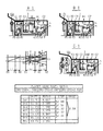
近年実用化された6ATは3種あり、4個の構成要素を持った2個の遊星歯車列の、3個の構成要素に選択的に非減速回転と減速用遊星歯車を介した減速回転を入力し、そのうちの2個の構成要素にブレーキを配し、残りの1個の構成要素を出力する方式が大部分を占め、減速回転の入力個数を1個とした特許文献1と2個とした特許文献2の2種類が存在する。残りの1種は変速段により3個の遊星歯車列の組換えを行う特許文献3に示されたもので、何れも5個のクラッチ及びブレーキの2個を選択的に締結することにより変速段が決定される構造となっている。この3種のうち、隣り合う変速段の変速比の段間差を比較的小さく取れる方式の一つとして特許文献2のリングギアを出力とする4ATと同じ形態のラビニョー遊星歯車を用いた組み合わせがあり、シンプルな構造で配置できることもあって一番多く実用化されている。但し、特許文献2の形態では前進1速〜4速段で減速用遊星歯車を介した大きなトルクとなる減速回転が変速用遊星ギアに入力する強度的に不利となる点と、高速段の前進4速−5速段及び前進5速−6速段の変速比の段間差が少し大きくなる問題を有している。加えてラビニョー遊星歯車の欠点として、ダブルピニオン遊星歯車を用いるため噛合い歯車が増え効率的に不利となること及び歯面荷重を分散して伝えるピニオン遊星歯車の個数に限界が生じる強度面の弱点がある。又、ラビニョー遊星歯車では本件出願図の図8、図9のType0、1に示した如く、ロングピニオン遊星歯車Paと噛合うピニオン遊星歯車Pb、サンギアS1及びリングギアR1の噛合いベクトルがそれぞれ異なるためロングピニオン遊星歯車が傾き、噛合いが悪くなる欠点を有している。そのためラビニョー遊星歯車の基本形態であり利点でもあるロングピニオン遊星歯車による動力伝達方式を変えることも考慮しなければならない。尚、近年燃費向上のため原動機には低回転高トルクのディーゼルエンジンが用いられるようになり、強度的に不利となる特許文献2の形態に強度面に弱点があるラビニョー遊星歯車を用いるには一層の補強が望まれる。 There are three types of 6ATs that have been put into practical use in recent years. Two planetary gear trains with four components are selectively subjected to non-deceleration rotation and deceleration rotation via a planetary gear for deceleration. Patent Documents 1 and 2 in which most of them are input, the brakes are arranged on two of the components, and the remaining one component is output, and the number of inputs of the deceleration rotation is one. There are two types of the above-mentioned Patent Document 2. The remaining one is shown in Patent Document 3 in which three planetary gear trains are recombined according to the shift speed, and in either case, the shift speed is determined by selectively engaging two of the five clutches and brakes. Is determined. Of these three types, a combination using Ravigne planetary gears of the same form as 4AT that outputs the ring gear of Patent Document 2 as one of the methods that can take the difference between the gear ratios of adjacent gears relatively small. Yes, it is the most practical because it can be arranged with a simple structure. However, in the form of Patent Document 2, the decelerating rotation, which is a large torque via the decelerating planetary gear at the first to fourth forward speeds, is disadvantageous in terms of strength that is input to the shifting planetary gear, and the high-speed stage advance There is a problem that the difference between the gear ratios of the 4th-5th gear and the forward 5th-6th gear is slightly increased. In addition, the disadvantage of Ravigneaux planetary gears is that the use of double pinion planetary gears increases the number of meshing gears and is disadvantageous, and the weakness of the strength surface that limits the number of pinion planetary gears that distribute and distribute the tooth load. There is. The Ravigneaux planetary gears have different meshing vectors for the pinion planetary gear Pb, the sun gear S1 and the ring gear R1, which mesh with the long pinion planetary gear Pa, as shown in Type 0 and 1 of FIGS. For this reason, the long pinion planetary gear has a drawback that it is tilted and the meshing becomes worse. Therefore, it is necessary to consider changing the power transmission system using the long pinion planetary gear, which is the basic form and advantage of the Ravigneaux planetary gear. In recent years, a diesel engine with a low rotation and high torque has been used as a prime mover for improving fuel efficiency, and the Ravigneaux planetary gear having a weak point in strength in the form of Patent Document 2, which is disadvantageous in strength, is further used. Reinforcement of is desired.

乗用車で最も多用されている原動機をフロント側に横置きに配するFWD(Front Wheel Drive)車では特に変速機の軸方向の短縮化が要求され、特許文献2のラビニョー遊星歯車を用いた極めてコンパクトとなる6ATとしてSAE TECHNICAL PAPERに記載された非特許文献4があり、各部位の配置が特許文献5及び6で提案されている。この方式では前進1速〜4速段で減速用遊星歯車を介した大きなトルクとなる減速回転がラビニョー遊星歯車のダブルピニオン遊星歯車と噛合う小径のサンギアに入力されるため、このサンギアの歯面荷重が必然的に大きくなる。そのため歯車の歯幅を増やす必要が生じ、軸方向の短縮化が要求されるFWD車には向かなくなる。一般的に4ATに用いられるラビニョー遊星歯車ではダブルピニオン遊星歯車の数は2×3個であり、ダブルピニオン遊星歯車の数をスペース的に限界となる2×4個まで増やし歯面荷重を更に分散させると歯幅を増やす必要がなくなる。そのため非特許文献4では本件出願図の図29に示したように、サンギアS2と噛合うピニオン遊星歯車Pbの外径を小さくしてピニオン遊星歯車PbとリングギアR1との間にスペースを設け、遊星キャリアを構成する両サイド部材を連結する連結部材Pを配する工夫をしている。しかしながら、ピニオン遊星歯車Pbの歯数が小さくなり回転が増えて効率及び耐久上不利になるのに加えて、前進1速から原動機直結とするため前進1速−2速段の変速比の段間差をDCTのように小さくするにはサンギアS2とS1の歯数を近づけねばならず、ピニオン遊星歯車Pbの配置スペース上限界が生じる。又、ピニオン遊星歯車Pbの軸支軸を保持する遊星キャリアの肉厚がサンギアS1の外径との距離δで決まるためピニオン遊星歯車Pbの軸支軸の径を小さくしなければならず、この構造で前進1速−2速段の変速比の段間差をDCTのように小さくすることは困難となる。 In the FWD (Front Wheel Drive) vehicle in which the prime mover that is most frequently used in passenger cars is placed horizontally on the front side, especially in the axial direction of the transmission is required to be shortened, and extremely compact using the Ravigne planetary gear of Patent Document 2 Non-patent document 4 described in SAE TECHNICICAL PAPER as 6AT which becomes, and the arrangement of each part is proposed in patent documents 5 and 6. In this method, since the reduction rotation which becomes a large torque through the reduction planetary gear at the first to fourth forward speeds is input to the small-diameter sun gear engaged with the double pinion planetary gear of the Ravigne planetary gear, the tooth surface of the sun gear The load inevitably increases. Therefore, it is necessary to increase the tooth width of the gear, which is not suitable for an FWD vehicle that requires a reduction in the axial direction. The Ravigneaux planetary gear generally used for 4AT has 2 × 3 double pinion planetary gears. The number of double pinion planetary gears is increased to 2 × 4, which is the limit of space, and the tooth load is further distributed. This eliminates the need to increase the tooth width. Therefore, in Non-Patent Document 4, as shown in FIG. 29 of the present application diagram, the outer diameter of the pinion planetary gear Pb meshing with the sun gear S2 is reduced to provide a space between the pinion planetary gear Pb and the ring gear R1. A device is devised in which a connecting member P that connects both side members of the planetary carrier is arranged. However, the number of teeth of the pinion planetary gear Pb is reduced and the rotation is increased, which is disadvantageous in terms of efficiency and durability. In addition, since the first forward speed is directly connected to the prime mover, the speed ratio between the first forward speed and the second speed stage is reduced. In order to make the difference as small as DCT, the number of teeth of the sun gears S2 and S1 must be made close, and there is a limit on the space for arranging the pinion planetary gear Pb. Further, since the thickness of the planet carrier that holds the shaft support shaft of the pinion planetary gear Pb is determined by the distance δ from the outer diameter of the sun gear S1, the diameter of the shaft support shaft of the pinion planetary gear Pb must be reduced. With the structure, it becomes difficult to reduce the difference in gear ratio between the first forward speed and the second forward speed as in DCT.

又、この方式のラビニョー遊星歯車では遊星キャリアが長幅構造になるとともにブレーキとクラッチの摩擦部材を係止するため遊星キャリアがアンバランスとなり、遊星キャリアの両端を軸支する必要がある。しかしながら、非特許文献4では遊星キャリアを一端でしか軸支しない片持構造となっており振動や耐久上好ましくない。加えて、この遊星キャリアの軸方向の保持が相対回転の大きくなる径の大きな固定部となっており、遊星キャリアの軸支機構全体がロスを伴う不安定な構造となっている。 Further, in this type of Ravigneaux planetary gear, the planetary carrier has a long width structure, and the planetary carrier is unbalanced to lock the friction members of the brake and the clutch, so that both ends of the planetary carrier must be pivotally supported. However, Non-Patent Document 4 has a cantilever structure in which the planet carrier is supported only at one end, which is not preferable in terms of vibration and durability. In addition, the holding of the planet carrier in the axial direction serves as a fixed portion having a large diameter that increases relative rotation, and the entire planetary carrier support mechanism has an unstable structure with loss.

非特許文献4では減速用遊星歯車とラビニョー遊星歯車の外周径方向外側にクラッチとブレーキの摩擦部材を配したためコンパクトな構造となるが、ラビニョー遊星歯車のシングルピニオン遊星歯車と噛合うサンギアに減速回転を入力するクラッチドラムを、ブレーキで制動する構造となっている。このクラッチドラムは最高速段の前進6速段で制動され、連続高速走行状態において内周側に摩擦部材を係止するクラッチドラムに遠心力が作用せず潤滑油が排出され難くなり、摩擦部材の連れ回りロスが大きくなる欠点がある。このクラッチの摩擦部材は減速用遊星歯車の外周径方向外側に配され、減速用遊星歯車潤滑後の潤滑油が供給される構造となっており、減速用遊星歯車の潤滑油は常時必要なため制動時に潤滑油の供給を止めるわけにはいかなく、連れ回りロスが必然的に大きくなる。 In Non-Patent Document 4, the clutch and brake friction members are arranged on the outer periphery of the reduction planetary gear and the Ravigne planetary gear in the outer peripheral radial direction. The structure is such that the clutch drum that inputs is braked with a brake. This clutch drum is braked at the 6th forward speed of the highest speed stage, and in the continuous high speed running state, the centrifugal force does not act on the clutch drum that locks the friction member on the inner peripheral side, making it difficult for the lubricating oil to be discharged. There is a drawback that the accompanying loss increases. The friction member of this clutch is arranged on the outer peripheral radial direction outer side of the planetary gear for reduction, and has a structure in which lubricating oil after lubrication of the planetary gear for reduction is supplied, and the lubricating oil of the planetary gear for reduction is always required There is no way to stop the supply of lubricant during braking, and the following loss will inevitably increase.

更に、特許文献2の特性上の欠点とも言えるが、前進4速−5速段及び前進5速−6速段の変速比の段間差をDCTのように小さくするのは不可能なため、クラッチ1個を追加し全ての段間差を前進7速のDCTに負けず小さくできる8ATが燃費改善の有力手段となる。そうするにはラビニョー遊星歯車に6ATより更に大きな減速回転を入力しなければならず、各歯車にかかる負担は大きくサンギアS2とS1の歯数を近づけた4×2個のダブルピニオン遊星歯車の配置が必須になるとともに、ロングピニオン遊星歯車の傾きによる歯当たり悪化の改善が必要となる。当然クラッチ追加による摩擦部材の連れ回りロスも増えるため、摩擦部材の連れ回りロス低減を考慮しなければならない。このクラッチ1個を追加した8ATとしてRWD(Rear Wheel Drive)車用に実用化されたSAE TECHNICAL PAPERに記載された非特許文献7がある。ここで用いられているラビニョー遊星歯車に於けるピニオン遊星歯車の配置構造は非特許文献4と同じ本件出願図の図29に示した構造であるが、スペース的に余裕があるためサンギアS2の径を大きくし強度を向上させ、その結果サンギアS1との相対比を小さくすることが可能となり変速段の段間差が比較的小さくなっている。但し、サンギアS2とS1の相対比をもっと小さくすると全体の変速比が更にバランスの採れたものとなる。又、ラビニョー遊星歯車の遊星キャリアはRWD車では軸方向スペースに余裕があるため両端で軸支出来ており問題はないが、一方の軸支部がシングルピニオン遊星歯車の外径より大きな位置での軸支であり周速が速くなる不利な構造となっている。一方、スペースに余裕のないFWD車用での8AT化は非特許文献7に示された構造は採れなく工夫が必要となる。 Furthermore, although it can be said that it is a drawback in the characteristics of Patent Document 2, it is impossible to reduce the difference in gear ratio between the forward fourth speed-5th speed and the forward fifth speed-6th speed as in DCT. 8AT, which can add one clutch and reduce all inter-stage differences as much as the forward 7-speed DCT, is an effective means for improving fuel economy. In order to do so, the Ravigneaux planetary gear must be input at a reduced rotation speed greater than 6AT, and the load on each gear is large, and the arrangement of 4 × 2 double pinion planetary gears with the number of teeth of S2 and S1 being close Is essential, and it is necessary to improve the tooth contact deterioration due to the inclination of the long pinion planetary gear. Naturally, since the accompanying loss of the friction member due to the addition of the clutch also increases, it is necessary to consider the reduction of the accompanying loss of the friction member. There is Non-Patent Document 7 described in SAE TECHNIC PAPER that has been put to practical use for RWD (Rear Wheel Drive) vehicles as 8AT with one clutch added. The arrangement structure of the pinion planetary gear in the Ravigneaux planetary gear used here is the structure shown in FIG. 29 of the same application diagram as in Non-Patent Document 4, but the diameter of the sun gear S2 is sufficient because of the space. Is increased to improve the strength. As a result, the relative ratio with the sun gear S1 can be reduced, and the difference between the gears is relatively small. However, if the relative ratio between the sun gears S2 and S1 is further reduced, the overall transmission ratio is further balanced. In addition, the Ravigno planetary planetary carrier can be pivotally supported at both ends because there is enough space in the axial direction in RWD vehicles, but there is no problem, but the shaft at one shaft support is larger than the outer diameter of the single pinion planetary gear. It has a disadvantageous structure that increases the peripheral speed. On the other hand, the 8AT configuration for FWD vehicles with insufficient space cannot be adapted to the structure shown in Non-Patent Document 7 and requires some ingenuity.

ラビニョー遊星歯車の各ピニオン歯車のスペースを確保する手段として、本願出願人より特許文献8が提案されている。このラビニョー遊星歯車は本件で用いる4個の構成要素を有したものとは異なり、5個の構成要素を有したラビニョー遊星歯車に関する提案である。サンギアとシングルピニオン遊星歯車を軸支する遊星キャリアとリングギアからなる2列のシンプル遊星歯車の、一方のピニオン遊星歯車を伸ばしてロングピニオン遊星歯車とし、もう一方のショートピニオン遊星歯車と同一遊星キャリア内でダブルピニオン遊星歯車として噛合わせたラビニョー遊星歯車の、遊星キャリアの両サイド部材を2分割し3個のショートピニオン遊星歯車の軸支軸で両サイド部材を連結する構造である。この構造ではショートピニオン遊星歯車に対しロングピニオン遊星歯車の歯数を極端に小さくしなければ配置スペースに於いて成立せず、ロングピニオン遊星歯車の軸支軸の径は小さくなりショートピニオン遊星歯車の軸支軸のみで2分割した両サイド部材を連結しなければならない。又、遊星キャリアの一方のサイド部材が出力軸と一体となり片持構造とはなるが、出力軸がハウジングの2点で大容量の軸受けで軸支される構造となるため遊星キャリアを両端で軸支する必要はない。加えて、前進の減速段で動力が本件とは逆の径の大きなサンギアに入力するため歯面荷重が小さくなるとともに、ショートピニオン遊星歯車と噛合う径の小さなサンギアの負荷頻度は径の大きなサンギアより小さいため、歯幅を径の大きなサンギアと同等以下に押さえることができる。したがって、遊星キャリアの幅も小さくなり、連結軸となるショートピニオン遊星歯車の軸支軸の連結幅も小さくできるため3箇所の連結だけで剛性的な問題は出ないが、遊星キャリアの幅が大きくなり、しかもショートピニオン遊星歯車の歯幅が大きくなる本件では、ショートピニオン遊星歯車の軸支軸だけで両サイド部材を連結することは剛性上不十分となる。 As a means for ensuring the space of each pinion gear of the Ravigne planetary gear, Patent Document 8 has been proposed by the present applicant. The Ravigneaux planetary gear is a proposal for a Ravigneaux planetary gear having five components, unlike the one having four components used in the present case. A two-row simple planetary gear consisting of a planetary carrier and a ring gear that supports a sun gear and a single pinion planetary gear. This is a structure in which both side members of a planet carrier of a Ravigne planetary gear meshed as a double pinion planetary gear are divided into two, and both side members are connected by shaft support shafts of three short pinion planetary gears. In this structure, if the number of teeth of the long pinion planetary gear is not made extremely small relative to the short pinion planetary gear, it will not be established in the arrangement space, the diameter of the shaft support shaft of the long pinion planetary gear becomes small, and Both side members divided into two only by the shaft support shaft must be connected. In addition, one side member of the planet carrier is integrated with the output shaft to form a cantilever structure, but the output shaft is supported by a large-capacity bearing at two points on the housing. There is no need to support. In addition, since the power is input to the sun gear with the large diameter opposite to this case at the forward deceleration stage, the load on the tooth surface is reduced and the load frequency of the sun gear with the small diameter meshing with the short pinion planetary gear is large. Since it is smaller, the tooth width can be kept equal to or less than that of a sun gear having a large diameter. Accordingly, the width of the planet carrier is reduced, and the connection width of the shaft support shaft of the short pinion planetary gear serving as the connection shaft can be reduced. In addition, in the present case where the tooth width of the short pinion planetary gear becomes large, it is insufficient in rigidity to connect the both side members only by the shaft support shaft of the short pinion planetary gear.

本願は前項で述べたように、隣り合う変速段の変速比の段間差を小さくし、発進と変速時以外はトルクコンバータをロスのないロックアップ状態で用いることができる6〜8ATの提案であり、主願としてはトルクコンバータを用いない6〜8ATの提案である。FWD車用に実用化された6ATに用いられるトルクコンバータは、CVTや4ATで用いられている応答性とトルク伝達容量に難のあるトーラス内部圧で締結させるロックアップクラッチであり、ロックアップの多用は困難となる。特に低回転高トルクのディーゼルエンジンには向かない。したがって、このトルクコンバータには軸方向がコンパクトとなることに加え、入力継手内に独立した油圧係合室を備え、複面の摩擦面を持つロックアップクラッチを有する本願出願人が特許文献9で提案したような入力継手を適用しなければならない。又、トルクコンバータを用いないATの構造が本願出願人より特許文献10で提案されている。この方式は発進段となる前進1速と後進段で締結するブレーキB1を本件出願図の図27に示したのように交互に配された摩擦部材の円周方向中央部に貫通穴を開け、ハウジングよりこの貫通穴に冷却油を供給し滑らせてクリープや発進を行わせるものである。トルクコンバータを用いない他の方法としては入力継手に湿式クラッチを用いる方法や、発進段となる前進1速と後進段で締結するクラッチC1、C3を滑らせる方法も提案されているが、変速機内部のロスがクラッチに加わり滑りエネルギーが増し、車両のクリープ状態等常時摩擦部材を滑らさなければならない状況で不利となる。一方特許文献10のブレーキB1の滑り状態を表す本件出願図の図28に示した前進1速段の速度線図では、締結しているクラッチC1以外の全てのクラッチとブレーキの連れ回りトルクが発進力となるためブレーキB1を滑らすエネルギーがクラッチを滑らす方式と比べ少なくて済み、摩擦部材の冷却方式の容易さとともに有利となる。したがって、隣り合う変速段の変速比の段間差を小さく取れる方式と組み合わせれば燃費的に最良のATとなる。 As described in the previous section, the present application is a proposal of 6-8AT that can reduce the difference between the gear ratios of adjacent gears and can use the torque converter in a lock-up state without loss except at the time of starting and shifting. There is a proposal of 6-8AT not using a torque converter as a main application. The torque converter used in the 6AT, which has been put to practical use for FWD vehicles, is a lock-up clutch that is fastened with a torus internal pressure that is difficult to respond and torque transmission capacity used in CVT and 4AT. Will be difficult. Not suitable for diesel engines with low rotation and high torque. Therefore, in this torque converter, in addition to the axial direction being compact, the applicant of the present invention having a lock-up clutch having a separate hydraulic engagement chamber in the input joint and having a double friction surface is disclosed in Patent Document 9. Input joints as proposed must be applied. Further, an AT structure that does not use a torque converter has been proposed by the applicant of the present application in Patent Document 10. In this method, a through-hole is formed in the center in the circumferential direction of the friction member in which the brake B1 that is fastened at the first forward speed and the reverse speed as the starting stage is alternately arranged as shown in FIG. Cooling oil is supplied to the through hole from the housing and slid to cause creeping and starting. Other methods that do not use a torque converter include a method that uses a wet clutch for the input joint, and a method that slides the clutches C1 and C3 that are engaged at the first forward speed and the reverse speed as the starting stage. An internal loss is applied to the clutch to increase the slip energy, which is disadvantageous in situations where the friction member must always be slid, such as a creeping state of the vehicle. On the other hand, in the speed diagram of the first forward speed shown in FIG. 28 of the present application diagram showing the slipping state of the brake B1 of Patent Document 10, all the clutches other than the engaged clutch C1 and the accompanying torque of the brake start. Therefore, the energy for sliding the brake B1 is less than that for sliding the clutch, which is advantageous in addition to the ease of cooling the friction member. Therefore, the best AT in terms of fuel consumption can be achieved by combining with a method that can reduce the difference in gear ratio between adjacent gears.

ところで、FWD車では原動機と同軸となる変速機の入力軸と平行に出力軸が配され、入力軸と出力軸の回転方向が同じ方向になることが要求されるため、入力軸から中継軸を介してカウンターギアで減速して出力軸に動力を伝達する構造となっている。この減速比は3〜4必要であり、中継軸に小径となるカウンターギアを配し、出力軸の大径となるカウンターギアと噛合わせる構造としている。この動力伝達構造はモジュールの大きな小歯数と大歯数の噛合わせとなり歯面のスリップによるロスが大きくなるとともに、ATに限らずMTでもCVTでも重量が増え燃費的に負の要因となるばかりではなく、狭いエンジンルームの空間を更に狭めている。又、大径となるカウンターギアの干渉により入力軸上に配される部材の位置と径が制限を受ける。特にクラッチ1個を追加して前進8速とする場合このクラッチとリングギアの干渉が問題となる。 By the way, in an FWD vehicle, an output shaft is arranged in parallel with the input shaft of a transmission that is coaxial with the prime mover, and the rotation direction of the input shaft and the output shaft is required to be the same direction. It is structured to transmit power to the output shaft by decelerating through the counter gear. This reduction ratio needs to be 3-4, and a counter gear having a small diameter is arranged on the relay shaft and meshed with a counter gear having a large diameter of the output shaft. This power transmission structure meshes the large number of small teeth and large number of teeth of the module, and the loss due to slip of the tooth surface increases, and the weight increases not only in AT but also in MT and CVT, which becomes a negative factor in fuel consumption. Rather, the space in the narrow engine room is further narrowed. Further, the position and diameter of the member arranged on the input shaft are limited by the interference of the counter gear having a large diameter. In particular, when one clutch is added to achieve the forward 8-speed, the interference between the clutch and the ring gear becomes a problem.

特開昭52−149562JP 52-149562 A 特開平4−219553JP-A-4-219553 特開2003−35341JP2003-35341A SAE PAPER 2004−01−0651SAE PAPER 2004-01-0651 特開2000−220703JP2000-220703 特開2000−220704JP 2000-220704 A SAE PAPER 2007−01−1101SAE PAPER 2007-01-1101 特開昭62−113946JP-A-62-1113946 特開2008−196660JP2008-196660 特願2008−83909Japanese Patent Application No. 2008-83909

本発明の第1の課題は、前進6速及び8速度段の多段自動変速機に用いる4個の構成要素からなるラビニョー遊星歯車の形態を変えずに各構成歯車の耐久強度を増し、共有する遊星キャリアの軸支を安定させることである。 The first object of the present invention is to increase and share the durability of each component gear without changing the form of the four component Ravigne planetary gears used in the forward 6-speed and 8-speed multi-speed automatic transmissions. It is to stabilize the support of the planet carrier.

本発明の第2の課題は、前進6速及び8速度段の多段自動変速機に用いる4個の構成要素からなるラビニョー遊星歯車の形態を変えて高トルク対応の複合遊星歯車として各構成歯車の耐久強度を増し、共有する遊星キャリアの軸支を安定させることである。 The second object of the present invention is to change the configuration of the Ravigne planetary gear composed of four components used in the forward 6-speed and 8-speed multi-stage automatic transmission, and to change the configuration of each component gear as a high-torque composite planetary gear. It is to increase the durability and stabilize the support of the shared planetary carrier.

本発明の第3の課題は、複合遊星歯車と減速用遊星歯車及びクラッチ、ブレーキからなる前進6速及び8速度段の多段自動変速機の隣り合う変速段の変速比の段間差を小さくし、伝達ロスの大きな流体伝導装置を無くすか或いはロックアップ領域が拡大出来る流体伝導装置を用いてシンプルに配置するとともに、締結要素に配される摩擦部材の連れまわりロスの低減も含め燃費を向上さすことである。 The third object of the present invention is to reduce the difference in gear ratio between adjacent gears of a multi-speed automatic transmission with forward 6-speed and 8-speed multi-speed transmission composed of a compound planetary gear, a reduction planetary gear, a clutch, and a brake. In addition to eliminating a fluid transmission device with a large transmission loss or using a fluid transmission device that can expand the lock-up area, the fuel transmission device can be simply arranged, and the fuel consumption can be improved including the reduction of the dragging loss of the friction member arranged on the fastening element. That is.

本発明の第4の課題は、FWD車用の変速機に配される効率的に負の要因となる中継軸を廃止し、流体伝導装置を無くした前進6速から8速度段の多段自動変速機の燃費を更に向上させるとともに、エンジンルームのスペースを広げることである。 A fourth object of the present invention is to eliminate a relay shaft that is an efficient negative factor arranged in a transmission for an FWD vehicle, and eliminates a fluid conduction device, thereby allowing a multi-speed automatic transmission of 6 to 8 forward speeds. It is to further improve the fuel efficiency of the aircraft and increase the engine room space.

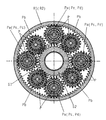
請求項1に係わる本発明は、前進6速後進1速或いは前進8速後進2速の変速段を得る多段自動変速機の複合遊星歯車に用いられるピニオン遊星歯車の個数をスペース限界まで増やすもので、第1と第2及び第3の課題を解決するための手段であり、シングルピニオン遊星歯車とダブルピニオン遊星歯車を軸方向2列に保持し、シングルピニオン遊星歯車とダブルピニオン遊星歯車の一方のピニオン遊星歯車を同一軸上で軸支するする遊星キャリアPと、シングルピニオン遊星歯車と噛合うサンギアS1及びリングギアR1と、ダブルピニオン遊星歯車のもう一方のピニオン遊星歯車と噛合うサンギアS2或いはシングルピニオン遊星歯車と同一軸上で軸支される一方のピニオン遊星歯車と噛合うリングギアR2とからなり、リングギアR1或いはリングギアR2に連結したリングギアR1を出力構成要素とする複合遊星歯車と、変速機の入力軸1の回転を減速する減速用遊星歯車と、複合遊星歯車のサンギアS2に減速用遊星歯車を経由した入力軸1の減速回転を入力するクラッチC1と、複合遊星歯車の遊星キャリアPに入力軸1の回転を入力するクラッチC2と、複合遊星歯車のサンギアS1に減速用遊星歯車を経由した入力軸1の減速回転或いは入力軸1の回転を入力するクラッチC3或いはC4と、複合遊星歯車の遊星キャリアPを制動するブレーキB1と、複合遊星歯車のサンギアS1を制動するブレーキB2とからなり、クラッチC1、C2、C3或いはC4及びブレーキB1、B2の何れか2個を選択的に締結することにより前進6速後進1速或いは前進8速後進2速の変速段を得る複合遊星歯車を用いた多段自動変速機であって、複合遊星歯車の各ピニオン遊星歯車を4個で構成するとともに遊星キャリアPを構成する両サイド部材を2分割し、シングルピニオン遊星歯車とダブルピニオン遊星歯車の一方のピニオン遊星歯車を同一軸上で軸支する4本の長梁軸と、ダブルピニオン遊星歯車のサンギアS2と噛合うもう一方のピニオン遊星歯車を軸支する4本の短梁軸で両サイド部材を連結するようになした。 According to the first aspect of the present invention, the number of pinion planetary gears used in a compound planetary gear of a multi-stage automatic transmission which obtains a forward 6-speed reverse 1-speed or a forward 8-speed reverse 2-speed is increased to the space limit. , Means for solving the first, second and third problems, wherein the single pinion planetary gear and the double pinion planetary gear are held in two rows in the axial direction, and one of the single pinion planetary gear and the double pinion planetary gear is A planet carrier P that supports the pinion planetary gear on the same axis, a sun gear S1 and a ring gear R1 that mesh with the single pinion planetary gear, and a sun gear S2 or single that meshes with the other pinion planetary gear of the double pinion planetary gear. The ring gear R1 includes a ring gear R2 that meshes with one pinion planetary gear that is supported on the same axis as the pinion planetary gear. Or a planetary gear having a ring gear R1 connected to the ring gear R2 as an output component, a planetary gear for reduction that reduces the rotation of the input shaft 1 of the transmission, and a planetary gear for reduction to the sun gear S2 of the compound planetary gear. The clutch C1 for inputting the decelerated rotation of the input shaft 1 via, the clutch C2 for inputting the rotation of the input shaft 1 to the planet carrier P of the compound planetary gear, and the planetary gear for reduction to the sun gear S1 of the compound planetary gear A clutch C3 or C4 for inputting the decelerated rotation of the input shaft 1 or the rotation of the input shaft 1, a brake B1 for braking the planet carrier P of the compound planetary gear, and a brake B2 for braking the sun gear S1 of the compound planetary gear, By selectively engaging either one of the clutches C1, C2, C3 or C4 and the brakes B1 and B2, forward 6-speed reverse 1-speed or forward 8-speed reverse A multi-stage automatic transmission using a compound planetary gear for obtaining a high speed gear stage, wherein each pinion planetary gear of the compound planetary gear is composed of four and both side members constituting the planet carrier P are divided into two parts. Four long beam shafts that support one pinion planetary gear of the pinion planetary gear and the double pinion planetary gear on the same axis, and the other pinion planetary gear that meshes with the sun gear S2 of the double pinion planetary gear are supported. Both side members are now connected by four short beam shafts.

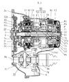
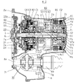
請求項2に係わる本発明は、前進6速後進1速或いは前進8速後進2速の変速段を得る多段自動変速機の複合遊星歯車の軸支に関するもので、第1と第2の課題を解決するための手段であり、変速機の入力軸1と出力軸を平行に配し、入力軸1を変速機ハウジングの両端で軸受け7a、7bで軸支し、入力軸1と同軸上の変速機ハウジングの中央部で出力軸に動力を伝達するカウンターギア3を軸受け7cで軸支し、カウンターギア3を挟んで入力軸1と同軸上の一方側に、複合遊星歯車とクラッチC2とブレーキB1を配し、入力軸1と同軸上のもう一方側に、減速用遊星歯車とクラッチC1、C3或いはC4とブレーキB2を配し、クラッチC1とサンギアS2を連結する連結部材12とクラッチC3或いはC4とサンギアS1を連結する連結部材11を、カウンターギア3の内周部を通して入力軸1の周りに径方向順に軸支させて配し、複合遊星歯車の遊星キャリアPを構成するシングルピニオン遊星歯車側サイド部材の内径L1とダブルピニオン遊星歯車側サイド部材の内径L2をサンギアS1の外径L3より小径としてラジアル軸受け7h、7iを配し、サンギアS1又はサンギアS1の連結部材11と入力軸1又は入力軸1とクラッチC2を連結する連結部材に軸支するとともにシングルピニオン遊星歯車側のサイド部材の両側にスラスト軸受け37a、37cを配し、複合遊星歯車の遊星キャリアPを保持するようになした。 The present invention according to claim 2 relates to a shaft support for a compound planetary gear of a multi-stage automatic transmission that obtains a forward 6-speed reverse 1-speed or a forward 8-speed reverse 2-speed gear, and has the first and second problems. In order to solve this problem, the input shaft 1 and the output shaft of the transmission are arranged in parallel, the input shaft 1 is supported by bearings 7a and 7b at both ends of the transmission housing, and the transmission is coaxial with the input shaft 1. A counter gear 3 that transmits power to the output shaft at the center of the machine housing is supported by a bearing 7c, and a composite planetary gear, a clutch C2, and a brake B1 are arranged on one side coaxial with the input shaft 1 with the counter gear 3 interposed therebetween. The planetary gear for reduction, the clutch C1, C3 or C4 and the brake B2 are arranged on the other side coaxial with the input shaft 1, and the connecting member 12 and the clutch C3 or C4 for connecting the clutch C1 and the sun gear S2 are arranged. And sun gear S1 The connecting member 11 is arranged so as to be axially supported around the input shaft 1 in the radial direction through the inner peripheral portion of the counter gear 3, and the single pinion planetary gear side member L1 constituting the planetary carrier P of the compound planetary gear Radial bearings 7h, 7i are arranged with the inner diameter L2 of the double pinion planetary gear side member smaller than the outer diameter L3 of the sun gear S1, and the sun gear S1 or the connecting member 11 of the sun gear S1 and the input shaft 1 or the input shaft 1 and the clutch C2 are connected. The thrust bearings 37a and 37c are arranged on both sides of the side member on the side of the single pinion planetary gear while being pivotally supported by the connecting member to be connected to hold the planet carrier P of the compound planetary gear.

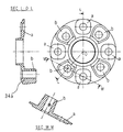
請求項3に係わる本発明は、前進6速後進1速或いは前進8速後進2速の変速段を得る多段自動変速機の複合遊星歯車の構造に関するもので、第1と第2の課題を解決するための手段であり、複合遊星歯車の各ピニオン遊星歯車は4本の長梁軸及び短梁軸上でニードルローラベアリングにより軸支され、4本の長梁軸及び短梁軸の両端をニードルローラベアリングの軸支径より小径とし、遊星キャリアPを構成するシングルピニオン遊星歯車側サイド部材の側面に貫通穴を有した4個の座aとサンギアS1の歯幅まで突き出た4個のボスbを円周方向に交互に設け、ダブルピニオン遊星歯車側サイド部材の外周を筒状に延材して径方向外周部外側にブレーキB1とクラッチC2の摩擦部材を係止するスプラインを設けるとともにシングルピニオン遊星歯車側サイド部材の座aとボスbの貫通穴に対抗する側面の同一円周位置に貫通穴を設け、両サイド部材の座a及び座aに対抗する貫通穴に4本の長梁軸の両端小径部をニードルローラベアリングの軸支径となる段付き部まで圧入し、両サイド部材のボスb及びボスbに対抗する貫通穴に4本の短梁軸の両端小径部をニードルローラベアリングの軸支径となる段付き部まで圧入し、4本の長梁軸と短梁軸の両端を絞めて両サイド部材を連結するようになした。 The present invention according to claim 3 relates to the structure of a compound planetary gear of a multi-stage automatic transmission that obtains a forward 6-speed reverse 1-speed or a forward 8-speed reverse 2-speed, and solves the first and second problems. Each pinion planetary gear of the compound planetary gear is supported by needle roller bearings on four long beam shafts and short beam shafts, and both ends of the four long beam shafts and short beam shafts are needled. Four seats a having a through-hole on the side surface of the single pinion planetary gear side member constituting the planet carrier P and four bosses b projecting to the tooth width of the sun gear S1. Are provided alternately in the circumferential direction, and the outer periphery of the double pinion planetary gear side member is formed into a cylindrical shape, and a spline for engaging the friction members of the brake B1 and the clutch C2 is provided outside the radial outer periphery, and a single pinio A through hole is provided at the same circumferential position on the side facing the through hole of the seat a of the planetary gear side member and the boss b, and four long beam shafts are provided in the through hole facing the seat a and the seat a of both side members. The small diameter parts at both ends of the shaft are press-fitted to the stepped part which becomes the shaft support diameter of the needle roller bearing. It was press-fitted to the stepped part, which is the shaft support diameter, and both side members were connected by narrowing the ends of the four long beam shafts and short beam shafts.

請求項4に係わる本発明は、前進6速後進1速或いは前進8速後進2速の変速段を得る多段自動変速機の複合遊星歯車の構造に関するもので、第1の課題を解決するための手段であり、複合遊星歯車の長梁軸に配したシングルピニオン遊星歯車とダブルピニオン遊星歯車の一方のピニオン遊星歯車を一体のロングピニオン遊星歯車として形成し、長梁軸上の両サイドにロングピニオン遊星歯車を軸支するニードルローラベアリングを配し、両ニードルローラベアリングの軸方向を規制する突起部を長梁軸の軸方向中央部に一体として設け、ロングピニオン遊星歯車をサンギアS1とリングギアR1に噛合わせるとともに、サンギアS2と噛合う短梁軸に配したピニオン遊星歯車と噛合わせるようになした。 The present invention according to claim 4 relates to the structure of a compound planetary gear of a multi-stage automatic transmission that obtains a forward 6-speed reverse 1-speed or a forward 8-speed reverse 2-speed gear stage. One pinion planetary gear arranged on the long beam shaft of the compound planetary gear and one pinion planetary gear of the double pinion planetary gear are formed as an integrated long pinion planetary gear, and the long pinion on both sides on the long beam shaft A needle roller bearing for supporting the planetary gear is provided, and a protrusion for restricting the axial direction of both needle roller bearings is provided integrally at the central portion in the axial direction of the long beam shaft. And a pinion planetary gear arranged on a short beam shaft that meshes with the sun gear S2.

請求項5に係わる本発明は、前進6速後進1速或いは前進8速後進2速の変速段を得る多段自動変速機の複合遊星歯車の構造に関するもので、第2の課題を解決するための手段であり、複合遊星歯車の長梁軸に配したシングルピニオン遊星歯車とダブルピニオン遊星歯車の一方のピニオン遊星歯車を各々ニードルローラベアリングで長梁軸上に隣接して軸支し、シングルピニオン遊星歯車をサンギアS1とリングギアR1に噛合わせるとともに、ダブルピニオン遊星歯車の一方のピニオン遊星歯車をサンギアS2と噛合う短梁軸に配したピニオン遊星歯車とリングギアR2に噛合わせ、リングギアR1とR2を連結するようになした。 The present invention according to claim 5 relates to a structure of a compound planetary gear of a multi-stage automatic transmission that obtains a forward 6-speed reverse 1-speed or a forward 8-speed reverse 2-speed gear stage, and to solve the second problem. One pinion planetary gear arranged on the long beam shaft of the compound planetary gear and one pinion planetary gear of the double pinion planetary gear are each supported by the needle roller bearing adjacent to the long beam shaft, and the single pinion planetary gear The gear meshes with the sun gear S1 and the ring gear R1, and one pinion planetary gear of the double pinion planetary gear meshes with the pinion planetary gear arranged on the short beam shaft meshing with the sun gear S2 and the ring gear R2, and the ring gear R1 R2 was linked.

請求項6に係わる本発明は、前進6速後進1速或いは前進8速後進2速の変速段を得る複合遊星歯車を用いた多段自動変速機のFWD車用に対する流体伝導装置を用いない伝達軸の配置に関するもので、第3と第4の課題を解決するための手段であり、変速機ハウジングは変速機前方に配された原動機との隔壁2dを保持するフロントケース2aとメインケース2b或いはリアケース2cからなり、回転変動吸収ダンパを介して原動機と連結した変速機の入力軸1を前端の隔壁2dに装着された円筒部材2fと後端のメインケース2b或いはリアケース2cに配された軸受け7a、7bで軸支し、フロントケース2aをメインケース2b内側の入力軸1の軸方向中央部まで延材してカウンターギア3を軸受け7cで軸支し、フロントケース2aと隔壁2dに囲まれたカウンターギア3前方に減速用遊星歯車とクラッチC1、C3或いはC4及びブレーキB2を配し、メインケース2b或いはリアケース2cに囲まれたカウンターギア3後方に複合遊星歯車とクラッチC2及びブレーキB1を配し、複合遊星歯車の出力構成要素となるリングギアR1或いはリングギアR2に連結したリングギアR1をサンギアS3とシングルピニオン遊星歯車を支持する遊星キャリアP3とリングギアR3からなる遊星減速歯車40のサンギアS3に連結し、遊星キャリアP3をメインケース2bに固定し、リングギアR3をカウンターギア3に連結し、カウンターギア3を出力軸が配されたディファレンシャル装置30のキャリアに連結したカウンターギア6と噛合わせるようになした。 The present invention according to claim 6 is a transmission shaft that does not use a fluid transmission device for an FWD vehicle of a multi-stage automatic transmission using a compound planetary gear that obtains a forward 6-speed reverse 1-speed or a forward 8-speed reverse 2-speed. The transmission housing is a means for solving the third and fourth problems, and the transmission housing has a front case 2a and a main case 2b that hold a partition wall 2d with a prime mover arranged in front of the transmission. The input shaft 1 of the transmission, which is composed of a case 2c and is connected to the prime mover via a rotation fluctuation absorbing damper, is a cylindrical member 2f mounted on the front end partition wall 2d and a rear end main case 2b or a bearing disposed on the rear case 2c. 7a and 7b, the front case 2a is extended to the axial center of the input shaft 1 inside the main case 2b, and the counter gear 3 is supported by the bearing 7c. A planetary gear for reduction, a clutch C1, C3 or C4 and a brake B2 are arranged in front of the counter gear 3 surrounded by the partition wall 2d, and a compound planetary gear is placed behind the counter gear 3 surrounded by the main case 2b or the rear case 2c. A ring gear R1 which is provided with a clutch C2 and a brake B1 and is connected to the ring gear R1 or the ring gear R2 serving as an output component of the compound planetary gear from the sun gear S3 and the planet carrier P3 and the ring gear R3 supporting the single pinion planetary gear. The planetary speed reduction gear 40 is connected to the sun gear S3, the planetary carrier P3 is fixed to the main case 2b, the ring gear R3 is connected to the counter gear 3, and the counter gear 3 is connected to the carrier of the differential device 30 provided with the output shaft. It meshes with the connected counter gear 6.

請求項7に係わる本発明は、前進6速後進1速或いは前進8速後進2速の変速段を得る複合遊星歯車を用いた多段自動変速機のFWD車用に対する構成部位の配置に関するもので、第3の課題を解決するための手段であり、変速機ハウジングは変速機前方に配された原動機との隔壁2dを保持するフロントケース2aとメインケース2bとリアケース2cからなり、回転変動吸収ダンパ又は流体伝導装置を介して原動機と連結した変速機の入力軸1を前端の隔壁2dに装着された円筒部材2fと後端のリアケース2cに配された軸受け7a、7bで軸支し、メインケース2bの軸方向中央部に設けられたL字型側壁でカウンターギア3を軸受け7cで軸支し、複合遊星歯車の出力構成要素となるリングギアR1或いはリングギアR2に連結したリングギアR1をカウンターギア3に連結し、カウンターギア3を入力軸1に平行に配した中継軸に連結されたカウンターギア4と噛合わせ、フロントケース2a側に中継軸と一体となるカウンターギア5を設け、出力軸が配されたディファレンシャル装置30のキャリアに連結したカウンターギア6と噛合わせるようになした。 The present invention according to claim 7 relates to the arrangement of components for an FWD vehicle of a multi-stage automatic transmission using a compound planetary gear that obtains a shift speed of forward 6-speed reverse 1-speed or forward 8-speed reverse 2-speed. A means for solving the third problem, wherein the transmission housing includes a front case 2a, a main case 2b, and a rear case 2c that hold a partition wall 2d with a prime mover disposed in front of the transmission, and includes a rotation fluctuation absorbing damper. Alternatively, an input shaft 1 of a transmission connected to a prime mover via a fluid conduction device is supported by bearings 7a and 7b disposed on a cylindrical member 2f mounted on a front partition wall 2d and a rear case 2c on the rear end. The counter gear 3 is pivotally supported by a bearing 7c with an L-shaped side wall provided in the axial center of the case 2b, and is connected to the ring gear R1 or the ring gear R2 that is an output component of the compound planetary gear. The ring gear R1 is connected to the counter gear 3, the counter gear 3 is meshed with the counter gear 4 connected to the relay shaft arranged in parallel with the input shaft 1, and the counter gear 5 integrated with the relay shaft on the front case 2a side. The counter gear 6 connected to the carrier of the differential device 30 provided with the output shaft is meshed with the counter gear 6.

請求項8に係わる本発明は、前進6速後進1速或いは前進8速後進2速の変速段を得る多段自動変速機の長梁軸に配したピニオン遊星歯車が偏荷重を受けない構造の複合遊星歯車を用いたFWD車用に対する配置に関するもので、第2と第3の課題を解決するための手段であり、カウンターギア3の前方に、リングギアR1、R2を有した複合遊星歯車とクラッチC2及びブレーキB1が配されたもので、リングギアR1、R2を有した複合遊星歯車のダブルピニオン遊星歯車側サイド部材の外周に、リングギアR1、R2の外径より小径となるクラッチC2のクラッチハブを前方に円筒状に延材して設けるとともにリングギアR1、R2の外径より大径となるブレーキB1のブレーキハブを後方に円筒状に延材して設け、ディファレンシャル装置30のキャリアに連結したカウンターギア6と軸方向同一位置に、内周とクラッチC2のクラッチハブ外周との間に摩擦部材を有するとともに入力軸1と連結するクラッチC2のクラッチドラムを配し、カウンターギア6と干渉しない軸方向後方位置に、ブレーキB1のブレーキハブを制動する摩擦部材或いはワンウェイクラッチOWCをメインケース2bとの間に配し、ダブルピニオン遊星歯車側のサイド部材の内径をサンギアS2の外径より小径にして軸受け7hで入力軸1に軸支するようになした。 The present invention according to claim 8 is a composite structure in which the pinion planetary gear arranged on the long beam shaft of the multi-stage automatic transmission that obtains the forward 6-speed reverse 1-speed or the forward 8-speed reverse 2-speed gear stage is not subjected to an eccentric load. The present invention relates to an arrangement for an FWD vehicle using a planetary gear, and is a means for solving the second and third problems. A compound planetary gear and a clutch having ring gears R1 and R2 in front of a counter gear 3 C2 and a brake B1 are arranged, and the clutch of the clutch C2 has a smaller diameter than the outer diameter of the ring gears R1 and R2 on the outer periphery of the double pinion planetary gear side member of the compound planetary gear having the ring gears R1 and R2. A hub is provided in a cylindrical shape at the front, and a brake hub of the brake B1 having a larger diameter than the outer diameter of the ring gears R1 and R2 is provided in a cylindrical shape at the rear as a differential. At the same axial position as the counter gear 6 connected to the carrier of the device 30, a clutch drum of the clutch C2 connected to the input shaft 1 and having a friction member between the inner periphery and the clutch hub outer periphery of the clutch C2, A friction member for braking the brake hub of the brake B1 or a one-way clutch OWC is disposed between the main case 2b and the inner diameter of the side member on the double pinion planetary gear side at the sun gear S2 at an axial rearward position that does not interfere with the counter gear 6. The outer diameter is smaller than the outer diameter of the input shaft 1 and is supported on the input shaft 1 by a bearing 7h.

請求項9に係わる本発明は、前進6速後進1速の変速段を得る多段自動変速機の複合遊星歯車に入力する減速機構の構造に関するもので、第3と第4の課題を解決するための手段であり、カウンターギア3の一方側に配される減速用遊星歯車とクラッチC1、C3及びブレーキB2は、サンギアS0とシングルピニオン遊星歯車を軸支する遊星キャリアP0とリングギアR0からなる減速用遊星歯車のサンギアS0が変速機ハウジングの内周円筒ボスに固定され、リングギアR0が変速機の入力軸1に連結され、遊星キャリアP0を構成する反カウンターギア3側のサイド部材の内周にクラッチC1、C3一体のクラッチドラムが連結され、減速用遊星歯車の外周径方向外側に円筒状に延材されて円筒部内周に反カウンターギア3側から軸方向順にクラッチC1とC3の摩擦部材を配するクラッチC1、C3一体のクラッチドラムが変速機ハウジングの内周円筒ボスに軸支されて減速用遊星歯車の反カウンターギア3側に配され、クラッチC1、C3一体のクラッチドラムの外周径方向外側に位置する変速機ハウジング内周にブレーキB2の摩擦部材が配されたもので、サンギアS2、S1に連結する連結部材12、11を減速用遊星歯車の外周径方向外側に連結部材12を連結部材11より反カウンターギア3側に位置するよう円筒状に延材して外周にクラッチC1、C3の摩擦部材を配し、連結部材11を前記クラッチC1、C3一体のクラッチドラムの外周径方向外側に円筒状に延材して外周にブレーキB2の摩擦部材を配し、変速機ハウジングの内周円筒ボスにクラッチC1、C2一体のクラッチドラムへの作動油供給回路を設けるようになした。 The present invention according to claim 9 relates to a structure of a speed reduction mechanism that inputs to a compound planetary gear of a multi-stage automatic transmission that obtains a shift speed of six forward speeds and one reverse speed, and to solve the third and fourth problems. The reduction planetary gear, the clutches C1, C3 and the brake B2 arranged on one side of the counter gear 3 are a reduction gear composed of a sun carrier S0 and a planet carrier P0 and a ring gear R0 supporting the single pinion planetary gear. The planetary gear sun gear S0 is fixed to the inner peripheral cylindrical boss of the transmission housing, the ring gear R0 is connected to the input shaft 1 of the transmission, and the inner periphery of the side member on the counter-counter gear 3 side constituting the planet carrier P0. Is connected to the clutch drum integrated with the clutches C1 and C3, and is extended in a cylindrical shape outside the outer peripheral radial direction of the planetary gear for reduction. A clutch drum integrated with clutches C1 and C3, in which the friction members of the clutches C1 and C3 are arranged in order, is pivotally supported by the inner peripheral cylindrical boss of the transmission housing and is arranged on the counter-counter gear 3 side of the reduction planetary gear. The friction member of the brake B2 is arranged on the inner periphery of the transmission housing located on the outer periphery side of the outer peripheral radial direction of the clutch drum integrated with C3, and the connecting members 12, 11 connected to the sun gears S2, S1 are connected to the outer periphery of the planetary gear for reduction. The connecting member 12 is extended in a cylindrical shape so as to be positioned on the counter-counter gear 3 side of the connecting member 11 on the radially outer side, and the friction members of the clutches C1 and C3 are arranged on the outer periphery. The integral clutch drum is cylindrically extended outside in the outer peripheral radial direction, the friction member of the brake B2 is arranged on the outer periphery, and the clutch C is connected to the inner peripheral cylindrical boss of the transmission housing. And no to provide a hydraulic oil supply circuit to the C2 integral of the clutch drum.

請求項10に係わる本発明は、前進8速後進2速の変速段を得る多段自動変速機の複合遊星歯車に入力する減速機構の構造に関するもので、第3と第4の課題を解決するための手段であり、カウンターギア3の一方側に配される減速用遊星歯車とクラッチC1、C3、C4及びブレーキB2は、サンギアS0とダブルピニオン遊星歯車を軸支する遊星キャリアP0とリングギアR0からなる減速用遊星歯車のサンギアS0が変速機ハウジングの内周円筒ボスに固定され、遊星キャリアP0を構成するカウンターギア3側のサイド部材に入力軸1が連結されるとともにもう一方のサイド部材に反カウンターギア3側に円筒状に延材するクラッチC4のクラッチハブが連結され、リングギアR0の外周にクラッチC1、C3一体のクラッチハブがクラッチC4のクラッチハブの外周径方向外側に円筒状に延材して連結され、カウンターギア3側が開口されクラッチC3を外周側として円周方向に2段となり、クラッチC1、C3一体のクラッチハブ及びクラッチC4のクラッチハブとの間に各々摩擦部材を配するクラッチC3、C4一体のクラッチドラムが変速機ハウジングの内周円筒ボスに軸支されて減速用遊星歯車の反カウンターギア3側に配され、反カウンターギア3側が開口されリングギアR0の外周径方向外側でクラッチC1、C3一体のクラッチハブとの間に摩擦部材を配するクラッチC1のクラッチドラムが減速用遊星歯車を挟んでクラッチC3、C4と対峙して配され、クラッチC3、C4一体のクラッチドラムの外周と変速機ハウジング内周の間にブレーキB2の摩擦部材が配されたもので、クラッチC3、C4一体のクラッチドラムをクラッチC1のクラッチドラムの外周径方向外側に延材してサンギアS1に連結する連結部材11と連結し、クラッチC1のクラッチドラムをサンギアS2に連結する連結部材12と連結し、変速機ハウジングの内周円筒ボスにクラッチC3、C4一体のクラッチドラムとクラッチC1のクラッチドラムへの作動油供給回路を設けるとともにクラッチC3、C4の摩擦部材専用の潤滑油供給回路を設けるようになした。 The present invention according to claim 10 relates to a structure of a speed reduction mechanism that inputs to a compound planetary gear of a multi-stage automatic transmission that obtains a forward speed of 8 speeds and a reverse speed of 2 speeds, and to solve the third and fourth problems. The planetary gear for reduction arranged on one side of the counter gear 3, the clutches C1, C3, C4 and the brake B2 from the planetary carrier P0 and the ring gear R0 that support the sun gear S0 and the double pinion planetary gear. The reduction planetary gear sun gear S0 is fixed to the inner peripheral cylindrical boss of the transmission housing, the input shaft 1 is connected to the side member on the counter gear 3 side constituting the planet carrier P0, and the other side member is opposed to the other side member. A clutch hub of a clutch C4 extending in a cylindrical shape is connected to the counter gear 3 side, and a clutch hub integrated with the clutches C1 and C3 is provided on the outer periphery of the ring gear R0. The clutch hub of the latch C4 is connected to the outer peripheral radial direction of the clutch hub in a cylindrical shape, the counter gear 3 side is opened, the clutch C3 is the outer peripheral side, and there are two stages in the circumferential direction. A clutch drum integrated with clutches C3 and C4, each of which is provided with a friction member between the clutch hub and the clutch hub of the clutch C4, is pivotally supported by the inner peripheral cylindrical boss of the transmission housing and is arranged on the counter-counter gear 3 side of the planetary gear for reduction. The clutch drum of the clutch C1 having a friction member disposed between the clutch gear C1 and the clutch hub integrated with the clutch C1 on the outer side in the outer peripheral radial direction of the ring gear R0 with the counter counter gear 3 side opened, and the clutch C3 with the planetary gear for reduction interposed therebetween. The brake B2 is disposed between the outer periphery of the clutch drum integrated with the clutches C3 and C4 and the inner periphery of the transmission housing. The clutch drum integrated with the clutches C3 and C4 is connected to the connecting member 11 that extends outward in the outer peripheral radial direction of the clutch drum of the clutch C1 and connects to the sun gear S1, and the clutch drum of the clutch C1 is connected to the clutch drum. A clutch drum integrated with the clutches C3 and C4 and a hydraulic oil supply circuit to the clutch drum of the clutch C1 are provided on the inner peripheral cylindrical boss of the transmission housing, and the friction of the clutches C3 and C4 is connected. A dedicated lubricating oil supply circuit is provided.

請求項1記載の構成では、シングルピニオン遊星歯車とダブルピニオン遊星歯車を軸方向2列に保持し、シングルピニオン遊星歯車とダブルピニオン遊星歯車の一方のピニオン遊星歯車を同一軸上で軸支するする遊星キャリアPと、シングルピニオン遊星歯車と噛合うサンギアS1及びリングギアR1と、ダブルピニオン遊星歯車のもう一方のピニオン遊星歯車と噛合うサンギアS2或いはシングルピニオン遊星歯車と同一軸上で軸支される一方のピニオン遊星歯車と噛合うリングギアR2とからなり、リングギアR1或いはリングギアR2に連結したリングギアR1を出力構成要素とする複合遊星歯車と、変速機の入力軸1の回転を減速する減速用遊星歯車と、複合遊星歯車のサンギアS2に減速用遊星歯車を経由した入力軸1の減速回転を入力するクラッチC1と、複合遊星歯車の遊星キャリアPに入力軸1の回転を入力するクラッチC2と、複合遊星歯車のサンギアS1に減速用遊星歯車を経由した入力軸1の減速回転或いは入力軸1の回転を入力するクラッチC3或いはC4と、複合遊星歯車の遊星キャリアPを制動するブレーキB1と、複合遊星歯車のサンギアS1を制動するブレーキB2とからなり、クラッチC1、C2、C3或いはC4及びブレーキB1、B2の何れか2個を選択的に締結することにより前進6速後進1速或いは前進8速後進2速の変速段を得る複合遊星歯車を用いた多段自動変速機であって、複合遊星歯車の各ピニオン遊星歯車を4個で構成するとともに遊星キャリアPを構成する両サイド部材を2分割し、シングルピニオン遊星歯車とダブルピニオン遊星歯車の一方のピニオン遊星歯車を同一軸上で軸支する4本の長梁軸と、ダブルピニオン遊星歯車のサンギアS2と噛合うもう一方のピニオン遊星歯車を軸支する4本の短梁軸で両サイド部材を連結するようになしたので、サンギアS2に入力する減速用遊星歯車を経由した大きなトルクによる歯面荷重が4個のピニオン遊星歯車に分散され歯幅を増やすことなく歯車の耐久強度を増すことができるとともに、サンギアS2と噛合うピニオン遊星歯車の効率及び耐久強度悪化に繋がる歯数減少を伴わずにサンギアS2の歯数をサンギアS1に近づけることが可能となり、低速度段に於ける変速比の段間差を小さくできる。 In the configuration according to claim 1, the single pinion planetary gear and the double pinion planetary gear are held in two rows in the axial direction, and one pinion planetary gear of the single pinion planetary gear and the double pinion planetary gear is supported on the same axis. The planetary carrier P, the sun gear S1 and the ring gear R1 meshing with the single pinion planetary gear, and the sun gear S2 meshing with the other pinion planetary gear of the double pinion planetary gear or the single pinion planetary gear are supported on the same axis. It comprises a ring gear R2 meshing with one pinion planetary gear, and the rotation of the input shaft 1 of the transmission and the compound planetary gear having the ring gear R1 connected to the ring gear R2 as an output component and the transmission input shaft 1 is decelerated. Reduced rotation of the input shaft 1 via the planetary gear for reduction and the sun gear S2 of the compound planetary gear via the planetary gear for reduction The clutch C1 for input, the clutch C2 for inputting the rotation of the input shaft 1 to the planet carrier P of the compound planetary gear, and the reduced rotation of the input shaft 1 via the reduction planetary gear or the input shaft 1 to the sun gear S1 of the compound planetary gear A clutch C3 or C4 for inputting the rotation of the engine, a brake B1 for braking the planet carrier P of the compound planetary gear, and a brake B2 for braking the sun gear S1 of the compound planetary gear, and the clutch C1, C2, C3 or C4 and the brake A multi-stage automatic transmission using a compound planetary gear using a compound planetary gear that obtains a forward 6-speed reverse 1-speed or a forward 8-speed reverse 2-speed by selectively engaging any one of B1 and B2. Each pinion planetary gear of the gear is composed of four pieces, and both side members constituting the planet carrier P are divided into two so that the single pinion planetary gear and the double pin Four long beam shafts that support one pinion planetary gear of the on planetary gear on the same axis, and four short beams that support the other pinion planetary gear that meshes with the sun gear S2 of the double pinion planetary gear Since both side members are connected by the shaft, the tooth load due to a large torque via the reduction planetary gear input to the sun gear S2 is distributed to the four pinion planetary gears, and the gear width is increased without increasing the tooth width. The durability can be increased and the efficiency of the pinion planetary gear meshing with the sun gear S2 and the number of teeth of the sun gear S2 can be made closer to the sun gear S1 without decreasing the number of teeth leading to deterioration of the durability. It is possible to reduce the difference between the gear ratios in.

請求項2記載の構成では、変速機の入力軸1と出力軸を平行に配し、入力軸1を変速機ハウジングの両端で軸受け7a、7bで軸支し、入力軸1と同軸上の変速機ハウジングの中央部で出力軸に動力を伝達するカウンターギア3を軸受け7cで軸支し、カウンターギア3を挟んで入力軸1と同軸上の一方側に、複合遊星歯車とクラッチC2とブレーキB1を配し、入力軸1と同軸上のもう一方側に、減速用遊星歯車とクラッチC1、C3或いはC4とブレーキB2を配し、クラッチC1とサンギアS2を連結する連結部材12とクラッチC3或いはC4とサンギアS1を連結する連結部材11を、カウンターギア3の内周部を通して入力軸1の周りに径方向順に軸支させて配し、複合遊星歯車の遊星キャリアPを構成するシングルピニオン遊星歯車側サイド部材の内径L1とダブルピニオン遊星歯車側サイド部材の内径L2をサンギアS1の外径L3より小径としてラジアル軸受け7h、7iを配し、サンギアS1又はサンギアS1の連結部材11と入力軸1又は入力軸1とクラッチC2を連結する連結部材に軸支するとともにシングルピニオン遊星歯車側のサイド部材の両側にスラスト軸受け37a、37cを配し、複合遊星歯車の遊星キャリアPを保持するようになしたので、複合遊星歯車全体の振動が低減し耐久性が向上する。 In the configuration according to claim 2, the input shaft 1 and the output shaft of the transmission are arranged in parallel, the input shaft 1 is supported by bearings 7a and 7b at both ends of the transmission housing, and the transmission is coaxial with the input shaft 1. A counter gear 3 that transmits power to the output shaft at the center of the machine housing is supported by a bearing 7c, and a composite planetary gear, a clutch C2, and a brake B1 are arranged on one side coaxial with the input shaft 1 with the counter gear 3 interposed therebetween. The planetary gear for reduction, the clutch C1, C3 or C4 and the brake B2 are arranged on the other side coaxial with the input shaft 1, and the connecting member 12 and the clutch C3 or C4 for connecting the clutch C1 and the sun gear S2 are arranged. And a connecting member 11 for connecting the sun gear S1 and the input gear 1 through the inner periphery of the counter gear 3 in the radial direction are arranged in order in the radial direction, and a single pinion play constituting a planet carrier P of the compound planetary gear is provided. Radial bearings 7h and 7i are arranged such that the inner diameter L1 of the gear side member and the inner diameter L2 of the double pinion planetary gear side member are smaller than the outer diameter L3 of the sun gear S1, and the connecting member 11 of the sun gear S1 or sun gear S1 and the input shaft 1 are arranged. Alternatively, it is supported by a connecting member that connects the input shaft 1 and the clutch C2, and the thrust bearings 37a and 37c are arranged on both sides of the side member on the single pinion planetary gear side to hold the planet carrier P of the compound planetary gear. As a result, the vibration of the entire compound planetary gear is reduced and the durability is improved.

請求項3記載の構成では、複合遊星歯車の各ピニオン遊星歯車は4本の長梁軸及び短梁軸上でニードルローラベアリングにより軸支され、4本の長梁軸及び短梁軸の両端をニードルローラベアリングの軸支径より小径とし、遊星キャリアPを構成するシングルピニオン遊星歯車側サイド部材の側面に貫通穴を有した4個の座aとサンギアS1の歯幅まで突き出た4個のボスbを円周方向に交互に設け、ダブルピニオン遊星歯車側サイド部材の外周を筒状に延材して径方向外周部外側にブレーキB1とクラッチC2の摩擦部材を係止するスプラインを設けるとともにシングルピニオン遊星歯車側サイド部材の座aとボスbの貫通穴に対抗する側面の同一円周位置に貫通穴を設け、両サイド部材の座a及び座aに対抗する貫通穴に4本の長梁軸の両端小径部をニードルローラベアリングの軸支径となる段付き部まで圧入し、両サイド部材のボスb及びボスbに対抗する貫通穴に4本の短梁軸の両端小径部をニードルローラベアリングの軸支径となる段付き部まで圧入し、4本の長梁軸と短梁軸の両端を絞めて両サイド部材を連結するようになしたので、遊星キャリアの剛性が確保出来るとともに成形が簡素化される。 In the configuration according to claim 3, each pinion planetary gear of the compound planetary gear is supported by needle roller bearings on the four long beam shafts and the short beam shafts, and both ends of the four long beam shafts and the short beam shafts are supported. Four seats a having a through-hole on the side surface of the single pinion planetary gear side member constituting the planet carrier P, and four bosses protruding to the tooth width of the sun gear S1. b is provided alternately in the circumferential direction, the outer periphery of the double pinion planetary gear side member is formed in a cylindrical shape, and a spline for engaging the friction members of the brake B1 and the clutch C2 is provided outside the radial outer periphery. A through hole is provided at the same circumferential position on the side facing the through hole of the pinion planetary gear side member a and the boss b, and four long beams are provided in the through hole facing the seat a and the seat a of both side members. Both ends of the shaft The diameter portion is press-fitted to the stepped portion that becomes the shaft support diameter of the needle roller bearing, and the small diameter portions at both ends of the four short beam shafts are inserted into the through holes that oppose the boss b of both side members and the shaft of the needle roller bearing. Press-fit to the stepped part that becomes the support diameter, and squeeze the ends of the four long beam shafts and the short beam shafts to connect both side members, ensuring the rigidity of the planetary carrier and simplifying the molding Is done.

請求項4記載の構成では、複合遊星歯車の長梁軸に配したシングルピニオン遊星歯車とダブルピニオン遊星歯車の一方のピニオン遊星歯車を一体のロングピニオン遊星歯車として形成し、長梁軸上の両サイドにロングピニオン遊星歯車を軸支するニードルローラベアリングを配し、両ニードルローラベアリングの軸方向を規制する突起部を長梁軸の軸方向中央部に一体として設け、ロングピニオン遊星歯車をサンギアS1とリングギアR1に噛合わせるとともに、サンギアS2と噛合う短梁軸に配したピニオン遊星歯車と噛合わせるようになしたので、長梁軸の曲げに対する剛性が上がり、偏荷重が加わった場合のロングピニオン遊星歯車の傾きを押さえることができるとともに総ころ方式の両ニードルローラベアリングの間座も必要としない。 In the configuration of claim 4, one pinion planetary gear of the single pinion planetary gear and the double pinion planetary gear arranged on the long beam shaft of the compound planetary gear is formed as an integrated long pinion planetary gear, A needle roller bearing that pivotally supports a long pinion planetary gear is arranged on the side, and a protrusion that regulates the axial direction of both needle roller bearings is provided integrally in the axial center of the long beam shaft, and the long pinion planetary gear is a sun gear S1. And the ring gear R1 and the pinion planetary gear arranged on the short beam shaft that meshes with the sun gear S2, so that the rigidity against bending of the long beam shaft is improved and the long when the eccentric load is applied. It can suppress the inclination of the pinion planetary gear and does not require a spacer between the full roller type needle roller bearings. .

請求項5記載の構成では、複合遊星歯車の長梁軸に配したシングルピニオン遊星歯車とダブルピニオン遊星歯車の一方のピニオン遊星歯車を各々ニードルローラベアリングで長梁軸上に隣接して軸支し、シングルピニオン遊星歯車をサンギアS1とリングギアR1に噛合わせるとともに、ダブルピニオン遊星歯車の一方のピニオン遊星歯車をサンギアS2と噛合う短梁軸に配したピニオン遊星歯車とリングギアR2に噛合わせ、リングギアR1とR2を連結するようになしたので、2個のピニオン遊星歯車を配した長梁軸には各々1方向の荷重しか作用せずピニオン遊星歯車の噛合いが悪くなることはない。 In the configuration according to claim 5, one pinion planetary gear of the single pinion planetary gear and the double pinion planetary gear arranged on the long beam shaft of the compound planetary gear is supported by the needle roller bearing adjacent to the long beam shaft. The single pinion planetary gear meshes with the sun gear S1 and the ring gear R1, and one pinion planetary gear of the double pinion planetary gear meshes with the pinion planetary gear and the ring gear R2 arranged on the short beam shaft meshing with the sun gear S2. Since the ring gears R1 and R2 are connected to each other, the long beam shaft provided with two pinion planetary gears is only subjected to a load in one direction, and the engagement of the pinion planetary gears is not deteriorated.

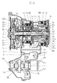
請求項6記載の構成では、変速機ハウジングは変速機前方に配された原動機との隔壁2dを保持するフロントケース2aとメインケース2b或いはリアケース2cからなり、回転変動吸収ダンパを介して原動機と連結した変速機の入力軸1を前端の隔壁2dに装着された円筒部材2fと後端のメインケース2b或いはリアケース2cに配された軸受け7a、7bで軸支し、フロントケース2aをメインケース2b内側の入力軸1の軸方向中央部まで延材してカウンターギア3を軸受け7cで軸支し、フロントケース2aと隔壁2dに囲まれたカウンターギア3前方に減速用遊星歯車とクラッチC1、C3或いはC4及びブレーキB2を配し、メインケース2b或いはリアケース2cに囲まれたカウンターギア3後方に複合遊星歯車とクラッチC2及びブレーキB1を配し、複合遊星歯車の出力構成要素となるリングギアR1或いはリングギアR2に連結したリングギアR1をサンギアS3とシングルピニオン遊星歯車を支持する遊星キャリアP3とリングギアR3からなる遊星減速歯車40のサンギアS3に連結し、遊星キャリアP3をメインケース2bに固定し、リングギアR3をカウンターギア3に連結し、カウンターギア3を出力軸が配されたディファレンシャル装置30のキャリアに連結したカウンターギア6と噛合わせるようになしたので、隣り合う変速段の変速比の段間差を小さく出来る前進6速から8速度段の変速装置部とその出力を逆回転に換える遊星減速歯車40を入力軸1の周りにコンパクトに配することができるとともに、効率的に負の要因となる中継軸が廃止でき、FWD車用のATとして最高の燃費向上が可能となる。又、出力軸に配されるカウンターギア6との干渉がなくなるため、入力軸1の前方側の径を上げクラッチC4を追加した前進8速の入力装置部をコンパクトに配することができる。尚、フロントケース2aにカウンターギア3を配したことによりメインケース2bをリアケース2cと一体にできることや、ブレーキB1の冷却供給孔を配した端部をメインケース2bに一体として設けることができる。 In the configuration according to claim 6, the transmission housing includes a front case 2a and a main case 2b or a rear case 2c that hold a partition wall 2d with a prime mover disposed in front of the transmission, and the prime mover is connected to the prime mover via a rotation fluctuation absorbing damper. The input shaft 1 of the connected transmission is pivotally supported by a cylindrical member 2f mounted on the partition wall 2d at the front end and bearings 7a and 7b disposed on the rear case main case 2b or the rear case 2c, and the front case 2a is supported by the main case. 2b extends to the axial center of the input shaft 1 and supports the counter gear 3 with a bearing 7c. In front of the counter gear 3 surrounded by the front case 2a and the partition wall 2d, a planetary gear for reduction and a clutch C1, C3 or C4 and the brake B2 are arranged, and the compound planetary gear and clutch are located behind the counter gear 3 surrounded by the main case 2b or the rear case 2c. 2 and the brake B1, and the ring gear R1 connected to the ring gear R1 or the ring gear R2 as an output component of the compound planetary gear is composed of the sun gear S3, the planet carrier P3 that supports the single pinion planetary gear, and the ring gear R3. It is connected to the sun gear S3 of the planetary reduction gear 40, the planet carrier P3 is fixed to the main case 2b, the ring gear R3 is connected to the counter gear 3, and the counter gear 3 is connected to the carrier of the differential device 30 provided with the output shaft. Since the counter gear 6 is meshed with the transmission gear section, the gear ratio of the forward 6 speed to the 8 speed stage which can reduce the difference between the gear ratios of adjacent speed stages and the planetary reduction gear 40 which changes the output to the reverse rotation. Can be arranged around the input shaft 1 in a compact manner, and a relay shaft that efficiently becomes a negative factor Can stop, the best fuel economy improvement is possible as AT for FWD cars. Further, since there is no interference with the counter gear 6 arranged on the output shaft, it is possible to compactly arrange a forward 8-speed input device portion in which the diameter of the front side of the input shaft 1 is increased and the clutch C4 is added. In addition, the main case 2b can be integrated with the rear case 2c by arranging the counter gear 3 in the front case 2a, and the end portion provided with the cooling supply hole of the brake B1 can be provided integrally with the main case 2b.

請求項7記載の構成では、変速機ハウジングは変速機前方に配された原動機との隔壁2dを保持するフロントケース2aとメインケース2bとリアケース2cからなり、回転変動吸収ダンパ又は流体伝導装置を介して原動機と連結した変速機の入力軸1を前端の隔壁2dに装着された円筒部材2fと後端のリアケース2cに配された軸受け7a、7bで軸支し、メインケース2bの軸方向中央部に設けられたL字型側壁でカウンターギア3を軸受け7cで軸支し、複合遊星歯車の出力構成要素となるリングギアR1或いはリングギアR2に連結したリングギアR1をカウンターギア3に連結し、カウンターギア3を入力軸1に平行に配した中継軸に連結されたカウンターギア4と噛合わせ、フロントケース2a側に中継軸と一体となるカウンターギア5を設け、出力軸が配されたディファレンシャル装置30のキャリアに連結したカウンターギア6と噛合わせるようになしたので、隣り合う変速段の変速比の段間差を小さくできるFWD車用の前進6速から8速度段の変速装置部を入力軸1の周りにコンパクトに配することができるとともに燃費向上が可能となる。尚、回転変動吸収ダンパを介して原動機と連結した場合、他に類を見ないコンパクトさとなる。 According to the seventh aspect of the present invention, the transmission housing includes a front case 2a, a main case 2b, and a rear case 2c that hold a partition wall 2d with a prime mover disposed in front of the transmission, and includes a rotation fluctuation absorbing damper or a fluid conduction device. The input shaft 1 of the transmission connected to the prime mover is pivotally supported by the cylindrical member 2f mounted on the partition wall 2d at the front end and the bearings 7a and 7b disposed on the rear case 2c at the rear end, and the axial direction of the main case 2b The counter gear 3 is pivotally supported by a bearing 7c with an L-shaped side wall provided in the center, and the ring gear R1 that is connected to the ring gear R1 or the ring gear R2 as an output component of the compound planetary gear is connected to the counter gear 3. The counter gear 3 is meshed with the counter gear 4 connected to the relay shaft arranged in parallel with the input shaft 1, and the counter gear 3 is integrated with the relay shaft on the front case 2a side. -Since the gear 5 is provided and meshed with the counter gear 6 connected to the carrier of the differential device 30 provided with the output shaft, it is possible to reduce the difference between the gear ratios of adjacent gear speeds. A transmission unit of 6th to 8th speed stages can be compactly arranged around the input shaft 1 and fuel efficiency can be improved. In addition, when it connects with a motor | power_engine via a rotation fluctuation | variation absorption damper, it becomes an unprecedented compact.

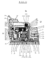
請求項8記載の構成では、第1と第2及び第4の課題を解決するための手段であり、カウンターギア3の前方に、リングギアR1、R2を有した複合遊星歯車とクラッチC2及びブレーキB1が配されたもので、リングギアR1、R2を有した複合遊星歯車のダブルピニオン遊星歯車側サイド部材の外周に、リングギアR1、R2の外径より小径となるクラッチC2のクラッチハブを前方に円筒状に延材して設けるとともにリングギアR1、R2の外径より大径となるブレーキB1のブレーキハブを後方に円筒状に延材して設け、ディファレンシャル装置30のキャリアに連結したカウンターギア6と軸方向同一位置に、内周とクラッチC2のクラッチハブ外周との間に摩擦部材を有するとともに入力軸1と連結するクラッチC2のクラッチドラムを配し、カウンターギア6と干渉しない軸方向後方位置に、ブレーキB1のブレーキハブを制動する摩擦部材或いはワンウェイクラッチOWCをメインケース2bとの間に配し、ダブルピニオン遊星歯車側のサイド部材の内径をサンギアS2の外径より小径にして軸受け7hで入力軸1に軸支するようになしたので、特にFWD車用に前進6速度段にクラッチC4を追加して径が大きくなる複合遊星歯車への入力装置部をカウンターギア3の後方に配することができ、偏荷重を受ける噛合いをしない複合遊星歯車を用いた前進8速後進2速の燃費の良いコンパクトな多段自動変速機が可能となる。 The structure according to claim 8 is a means for solving the first, second and fourth problems, and a compound planetary gear having a ring gear R1, R2 in front of the counter gear 3, a clutch C2, and a brake. B1 is arranged, and the clutch hub of the clutch C2 having a smaller diameter than the outer diameter of the ring gears R1 and R2 is provided on the outer periphery of the double pinion planetary gear side member of the compound planetary gear having the ring gears R1 and R2. The counter gear connected to the carrier of the differential device 30 is provided by extending the brake hub of the brake B1 having a larger diameter than the outer diameter of the ring gears R1 and R2 and extending the brake hub in a cylindrical shape at the rear. 6 has a friction member between the inner periphery and the outer periphery of the clutch hub of the clutch C2 at the same axial position as that of the clutch 6, and the clutch of the clutch C2 connected to the input shaft 1 A friction member for braking the brake hub of the brake B1 or a one-way clutch OWC is arranged between the main case 2b and a side member on the side of the double pinion planetary gear at an axially rearward position where the ram is arranged and does not interfere with the counter gear 6. The inner planetary gear is made smaller than the outer diameter of the sun gear S2 and is supported by the input shaft 1 by the bearing 7h. Therefore, especially for FWD vehicles, the clutch C4 is added to the forward six speed stage to increase the diameter. There is a compact multi-stage automatic transmission with a good fuel efficiency of 8 forward speeds and 2 reverse speeds using a compound planetary gear that can displace the gear input device part behind the counter gear 3 and is not meshed to receive an offset load. It becomes possible.

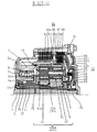
請求項9記載の構成では、カウンターギア3の一方側に配される減速用遊星歯車とクラッチC1、C3及びブレーキB2は、サンギアS0とシングルピニオン遊星歯車を軸支する遊星キャリアP0とリングギアR0からなる減速用遊星歯車のサンギアS0が変速機ハウジングの内周円筒ボスに固定され、リングギアR0が変速機の入力軸1に連結され、遊星キャリアP0を構成する反カウンターギア3側のサイド部材の内周にクラッチC1、C3一体のクラッチドラムが連結され、減速用遊星歯車の外周径方向外側に円筒状に延材されて円筒部内周に反カウンターギア3側から軸方向順にクラッチC1とC3の摩擦部材を配するクラッチC1、C3一体のクラッチドラムが変速機ハウジングの内周円筒ボスに軸支されて減速用遊星歯車の反カウンターギア3側に配され、クラッチC1、C3一体のクラッチドラムの外周径方向外側に位置する変速機ハウジング内周にブレーキB2の摩擦部材が配されたもので、サンギアS2、S1に連結する連結部材12、11を減速用遊星歯車の外周径方向外側に連結部材12を連結部材11より反カウンターギア3側に位置するよう円筒状に延材して外周にクラッチC1、C3の摩擦部材を配し、連結部材11を前記クラッチC1、C3一体のクラッチドラムの外周径方向外側に円筒状に延材して外周にブレーキB2の摩擦部材を配し、変速機ハウジングの内周円筒ボスにクラッチC1、C2一体のクラッチドラムへの作動油供給回路を設けるようになしたので、FWD車用の前進6速の複合遊星歯車への入力装置部をコンパクトにすることができるとともに、高速一定走行となる前進6速度段でクラッチC3のクラッチドラムが制動されることなく遠心力で潤滑油を排出するため摩擦部材による連れ回りロスが低減される。 In the configuration according to claim 9, the planetary gear for reduction arranged on one side of the counter gear 3, the clutches C1 and C3, and the brake B2 are the planet carrier P0 and the ring gear R0 that support the sun gear S0 and the single pinion planetary gear. The sun gear S0 of the planetary gear for reduction composed of is fixed to the inner peripheral cylindrical boss of the transmission housing, the ring gear R0 is connected to the input shaft 1 of the transmission, and the side member on the counter counter gear 3 side constituting the planet carrier P0. A clutch drum integrated with the clutches C1 and C3 is connected to the inner periphery of the clutch, and is extended in a cylindrical shape outwardly in the outer peripheral radial direction of the planetary gear for reduction. The clutch drum integrated with the clutches C1 and C3 for supporting the friction member is pivotally supported by the inner peripheral cylindrical boss of the transmission housing, so that the speed of the planetary gear for reduction is reduced. The friction member of the brake B2 is arranged on the inner gear 3 side, and the friction member of the brake B2 is arranged on the inner periphery of the transmission housing located on the outer periphery in the outer peripheral radial direction of the clutch drum integrated with the clutches C1 and C3. 12 and 11 are extended in a cylindrical shape so that the connecting member 12 is positioned on the counter counter gear 3 side of the connecting member 11 on the outer side in the outer peripheral radial direction of the reduction planetary gear, and friction members of the clutches C1 and C3 are arranged on the outer periphery. The connecting member 11 is formed in a cylindrical shape outside the outer peripheral radial direction of the clutch drum integrated with the clutches C1 and C3, the friction member of the brake B2 is disposed on the outer periphery, and the clutch C1 is disposed on the inner peripheral cylindrical boss of the transmission housing. Since the hydraulic oil supply circuit to the clutch drum integrated with C2 is provided, the input device section for the forward 6-speed compound planetary gear for FWD vehicles can be made compact. With wear, the clutch drum of the clutch C3 in the sixth forward speed stage to be a high speed constant running is brought about loss is reduced due to the friction member for discharging the lubricating oil in the centrifugal force without being braked.

請求項10記載の構成では、カウンターギア3の一方側に配される減速用遊星歯車とクラッチC1、C3、C4及びブレーキB2は、サンギアS0とダブルピニオン遊星歯車を軸支する遊星キャリアP0とリングギアR0からなる減速用遊星歯車のサンギアS0が変速機ハウジングの内周円筒ボスに固定され、遊星キャリアP0を構成するカウンターギア3側のサイド部材に入力軸1が連結されるとともにもう一方のサイド部材に反カウンターギア3側に円筒状に延材するクラッチC4のクラッチハブが連結され、リングギアR0の外周にクラッチC1、C3一体のクラッチハブがクラッチC4のクラッチハブの外周径方向外側に円筒状に延材して連結され、カウンターギア3側が開口されクラッチC3を外周側として円周方向に2段となり、クラッチC1、C3一体のクラッチハブ及びクラッチC4のクラッチハブとの間に各々摩擦部材を配するクラッチC3、C4一体のクラッチドラムが変速機ハウジングの内周円筒ボスに軸支されて減速用遊星歯車の反カウンターギア3側に配され、反カウンターギア3側が開口されリングギアR0の外周径方向外側で前記クラッチC1、C3一体のクラッチハブとの間に摩擦部材を配するクラッチC1のクラッチドラムが減速用遊星歯車を挟んでクラッチC3、C4と対峙して配され、クラッチC3、C4一体のクラッチドラムの外周と変速機ハウジング内周の間にブレーキB2の摩擦部材が配されたもので、クラッチC3、C4一体のクラッチドラムをクラッチC1のクラッチドラムの外周径方向外側に延材してサンギアS1に連結する連結部材11と連結し、クラッチC1のクラッチドラムをサンギアS2に連結する連結部材12と連結し、変速機ハウジングの内周円筒ボスにクラッチC3、C4一体のクラッチドラムとクラッチC1のクラッチドラムへの作動油供給回路を設けるとともにクラッチC3、C4の摩擦部材専用の潤滑油供給回路を設けるようになしたので、FWD車用の前進8速の複合遊星歯車への入力装置部をコンパクトにすることができるとともに、高速一定走行となる前進8速度段でクラッチC3、C4一体のクラッチドラムが制動されても専用の潤滑油供給回路で潤滑油の供給を止めれば摩擦部材による連れ回りロスが低減される。 In the configuration according to claim 10, the planetary gear for reduction arranged on one side of the counter gear 3, the clutches C1, C3, C4, and the brake B2 are connected to the planet carrier P0 and the ring that support the sun gear S0 and the double pinion planetary gear. A sun gear S0, which is a planetary gear for reduction composed of a gear R0, is fixed to the inner peripheral cylindrical boss of the transmission housing, and the input shaft 1 is connected to the side member on the counter gear 3 side constituting the planet carrier P0 and the other side. A clutch hub of the clutch C4 extending in a cylindrical shape on the counter-counter gear 3 side is connected to the member, and the clutch hub integrated with the clutches C1 and C3 is cylindrical on the outer periphery in the outer peripheral radial direction of the clutch hub of the clutch C4. The counter gear 3 side is opened and the clutch C3 is the outer peripheral side, so that there are two stages in the circumferential direction. A clutch drum integrated with the clutches C3 and C4, each of which is provided with a friction member between the clutch hub integrated with the clutches C1 and C3 and the clutch hub of the clutch C4, is pivotally supported by the inner peripheral cylindrical boss of the transmission housing, and the planetary gear for reduction. The clutch drum of the clutch C1 is disposed on the counter-counter gear 3 side, and the counter-counter gear 3 side is opened and a friction member is disposed between the clutch gear C1 and the clutch hub integrated with the clutch C3 outside the ring gear R0 in the outer peripheral radial direction. The friction member of the brake B2 is disposed between the outer periphery of the clutch drum integrated with the clutches C3 and C4 and the inner periphery of the transmission housing. The clutch drum integrated with C3 and C4 is extended to the outside in the outer peripheral radial direction of the clutch drum of the clutch C1 and connected to the sun gear S1. Connected to the connecting member 11, connected to the connecting member 12 connecting the clutch drum of the clutch C1 to the sun gear S2, the clutch drum integrated with the clutches C3 and C4 and the clutch drum of the clutch C1 to the clutch drum of the inner peripheral cylindrical boss of the transmission housing. Since the hydraulic oil supply circuit is provided and the lubricating oil supply circuit dedicated to the friction members of the clutches C3 and C4 is provided, it is possible to make the input device unit for the forward 8-speed compound planetary gear for FWD vehicles compact. In addition, even if the clutch drum integrated with the clutches C3 and C4 is braked at the eight forward speeds at a constant high speed, if the supply of the lubricating oil is stopped by a dedicated lubricating oil supply circuit, the accompanying loss due to the friction member is reduced. .

本発明は入力軸と出力軸が同一軸となるRWD(Rear Wheel Drive)車にも適用出来るが、実施例は本発明の特徴を活かしたコンパクトさが要求される前進6速以上の入力軸と出力軸がオフセットするFWD(Front Wheel Drive)車用の多段自動変速機とした。但し、RWD車用として本発明を前進8速後進2速の多段自動変速機に適用すれば複合遊星歯車の強度が向上するのに加えより適切な変速比を得ることができる。本発明は流体伝導装置を用いないことを主願としているが、流体伝導装置を用いた場合背景技術で述べた<入力継ぎ手内に独立した油圧係合室を備え、複面の摩擦面を持つロックアップクラッチを有する入力継手>との組み合わせも有効な燃費向上の手段としている。本発明ではこの入力継手との組み合わせの特許請求はしていないが、実施例では本件出願人が特開2008−196660で提案したものを用いた。 The present invention can also be applied to an RWD (Rear Wheel Drive) vehicle in which the input shaft and the output shaft are the same axis. However, the embodiment is directed to an input shaft having a forward speed of 6 or more that requires compactness utilizing the features of the present invention. A multi-stage automatic transmission for an FWD (Front Wheel Drive) vehicle whose output shaft is offset is used. However, when the present invention is applied to a multi-speed automatic transmission with 8 forward speeds and 2 reverse speeds for an RWD vehicle, the strength of the compound planetary gear can be improved and a more appropriate gear ratio can be obtained. The present invention is mainly intended not to use a fluid conduction device, but in the case of using a fluid conduction device, as described in the background art, <the input joint has an independent hydraulic engagement chamber, and has a double friction surface. A combination with an input joint having a lock-up clutch is also an effective means for improving fuel consumption. The present invention does not claim the combination with the input joint, but in the embodiment, the one proposed by the applicant in Japanese Patent Application Laid-Open No. 2008-196660 was used.

本発明の請求項1はFWD車とRWD車に於ける複合遊星歯車と複合遊星歯車を用いた多段自動変速機であり、そのFWD車用の多段自動変速機を請求項2として図8、図9、図18、図28及び図29を除く全ての図面に示す。請求項3は複合遊星歯車の構造に関するもので図1から図7に示し、請求項4はその1種であるラビニョー遊星歯車方式の複合遊星歯車100Aの構造を図1、図3、図4、図5及び図6に示し、請求項5はもう1種のラビニョー遊星歯車方式とは異なる複合遊星歯車100Bの構造を図2、図3、図4、図5及び図6に示したものである。尚、本発明に於ける複合遊星歯車の各歯車の配置を示す図6と比較するため、非特許文献4と7に用いられたラビニョー遊星歯車の各歯車の配置を図29に示した。又、複合遊星歯車100Aと100Bの内部歯車に対する動力の流れ方、及び力の加わり方の違いを図8と図9に示した。請求項6は本発明の複合遊星歯車を用いた前進6速<A−1>と前進8速<A−2>の2軸式多段自動変速機であり、全体構造を図10と図11にスケルトンと変速比を図16と図17に示し、詳細構造を図19から図22に示す。請求項7は本発明の複合遊星歯車を用いた流体伝導装置を無くした前進6速<B−1>と前進8速<B−2>及び流体伝導装置を用いた前進6速<C−1>と前進8速<C−2>の3軸式多段自動変速機であり、全体構造を図12から図17にスケルトンと変速比を図16と図17に示し、詳細構造を図23から図26に示す。尚、2軸と3軸式多段自動変速機の動力を伝達するカウンターギアの配置を図18に示した。請求項8は請求項5の複合遊星歯車100Bを請求項7に於ける3軸式多段自動変速機の前方に配置したものでその全体構造を図13と図15に示し、詳細構造を図25に示す。請求項9は本発明の前進6速後進1速の多段自動変速機に於ける複合遊星歯車の入力装置に関するもので、構造を図23に示す。同じく請求項10は本発明の前進8速後進2速の多段自動変速機に於ける複合遊星歯車の入力装置に関するもので、構造を図21と図26に示す。特に本発明の主願として流体伝導装置を用いない前進6速<A−1>と前進8速<A−2>の2軸式多段自動変速機及び前進6速<B−1>と前進8速<B−2>の3軸式多段自動変速機に於ける流体伝導装置の代わりとなるブレーキB1に関し、多段自動変速機の全体構造を図10から図13に示し、ブレーキB1の詳細構造を図27に示す。尚、流体伝導装置を用いないこの方式の前進1速度段に於ける各クラッチブレーキの連れ回りトルクが出力に及ぼすモーメント力を速度線図として図28に示した。 Claim 1 of the present invention is a multistage automatic transmission using a compound planetary gear and a compound planetary gear in an FWD vehicle and an RWD vehicle. The multistage automatic transmission for the FWD vehicle is shown in FIG. 9, all drawings except FIG. 18, FIG. 28 and FIG. Claim 3 relates to the structure of a compound planetary gear, which is shown in FIGS. 1 to 7, and claim 4 shows the structure of a compound planetary gear 100A of the Ravigne planetary gear system, which is one of them, as shown in FIGS. FIG. 5 and FIG. 6 show a structure of a compound planetary gear 100B different from another Ravigne planetary gear system in FIG. 5, FIG. 3, FIG. 4, FIG. 5, and FIG. . In addition, in order to compare with FIG. 6 which shows arrangement | positioning of each gear of the compound planetary gear in this invention, arrangement | positioning of each gear of the Ravigne planetary gear used by the nonpatent literatures 4 and 7 was shown in FIG. 8 and 9 show the difference in the way the power flows and how the force is applied to the internal gears of the compound planetary gears 100A and 100B. A sixth aspect of the present invention is a two-shaft multi-speed automatic transmission of 6 forward speed <A-1> and 8 forward speed <A-2> using the compound planetary gear of the present invention. The skeleton and the gear ratio are shown in FIGS. 16 and 17, and the detailed structure is shown in FIGS. The seventh aspect of the present invention is the sixth forward speed <B-1> and the eighth forward speed <B-2> without the fluid conduction device using the compound planetary gear of the present invention, and the sixth forward speed <C-1 using the fluid conduction device. > And forward 8-speed <C-2> three-shaft multi-speed automatic transmission, the overall structure is shown in FIGS. 12 to 17, the skeleton and the gear ratio are shown in FIGS. 16 and 17, and the detailed structure is shown in FIG. 26. FIG. 18 shows the arrangement of counter gears for transmitting the power of the 2-axis and 3-axis multi-stage automatic transmission. In the eighth aspect, the compound planetary gear 100B according to the fifth aspect is arranged in front of the three-shaft multi-stage automatic transmission according to the seventh aspect. The overall structure is shown in FIGS. 13 and 15, and the detailed structure is shown in FIG. Shown in Claim 9 relates to an input device for a compound planetary gear in a multi-speed automatic transmission of 6 forward speeds and 1 reverse speed according to the present invention. The structure is shown in FIG. Similarly, claim 10 relates to an input device for a compound planetary gear in a multi-speed automatic transmission with 8 forward speeds and 2 reverse speeds according to the present invention. The structure is shown in FIGS. In particular, as a main application of the present invention, a forward 6-speed <A-1> and a forward 8-speed <A-2> two-shaft multi-speed automatic transmission and a forward 6-speed <B-1> and a forward 8 that do not use a fluid conduction device. The overall structure of the multi-stage automatic transmission is shown in FIGS. 10 to 13 and the detailed structure of the brake B1 is shown in FIG. It shows in FIG. Incidentally, the moment force exerted on the output by the follow-up torque of each clutch brake in the first forward speed stage of this method without using the fluid conduction device is shown as a speed diagram in FIG.

図10から図15に用いた6種の多段自動変速機の実施例に於いて、前進6速後進1速の多段自動変速機には図1の100Aに示したラビニョー遊星歯車方式の複合遊星歯車を用い、前進8速後進2速の多段自動変速機には図2の100Bに示したラビニョー遊星歯車方式とは異なる複合遊星歯車を用いたが、変速段の数に関係なくどのタイプの複合遊星歯車をどの多段自動変速機に用いても良い。同様に図10から図13に用いた原動機と入力軸1の間の湿式と油圧式の回転変動吸収ダンパ及び図14と図15に用いたトルクコンバータとフルードカップリングの流体伝導装置に関しても適用が限定されるものではない。尚、ラビニョー遊星歯車の定義としては特許文献US2194954他多数の特許がラビニョー氏から提案されており、何れも同一遊星キャリア上にシンプルピニオン遊星歯車とダブルピニオン遊星歯車を複数列軸方向に配置し、ピニオン遊星歯車をロングピニオン遊星歯車として複数列の遊星歯車と共有させており、この構造をラビニョー遊星歯車と定義する。 In the embodiment of the six types of multi-speed automatic transmissions used in FIGS. 10 to 15, the compound planetary gear of the Ravigne planetary gear type shown in 100A of FIG. The multi-speed automatic transmission with 8 forward speeds and 2 reverse speeds uses a compound planetary gear different from the Ravigne planetary gear system shown in 100B of FIG. 2, but any type of compound planetary gear is used regardless of the number of gears. The gear may be used in any multistage automatic transmission. Similarly, the present invention can be applied to the wet and hydraulic rotational fluctuation absorbing dampers between the prime mover and the input shaft 1 used in FIGS. 10 to 13 and the torque converter and fluid coupling fluid conduction device used in FIGS. It is not limited. In addition, as a definition of Ravigneaux planetary gears, patent document US2194654 and many other patents have been proposed by Mr. Ravigneo, both of which arrange simple pinion planetary gears and double pinion planetary gears in the direction of multiple rows of axes on the same planet carrier, A pinion planetary gear is shared as a long pinion planetary gear with a plurality of planetary gears, and this structure is defined as a Ravigne planetary gear.

本発明に於けるラビニョー遊星歯車方式の複合遊星歯車100Aの構造を図1、図3、図4、図5及び図6に示す。複合遊星歯車100Aの遊星キャリアPとなるサイド部材34aと34bは分割されておりサイド部材34aを図4に、サイド部材34bを図5に示す。サイド部材34aを示す図4に於いて、側面には円周方向に4等分された位置に座aとボスbが交互に成形されており、座aとボスbの端面は機械加工でそれぞれ同じ高さに揃えられている。座aとボスbにはそれぞれ相対位置関係を有した円周方向同径となる4等分位置に機械加工でそれぞれ同じ大きさの貫通穴が開けられており、貫通穴の端部はテーパの面取りがなされている。もう一方のサイド部材34bを示す図5に於いて、側面にはサイド部材34aの座aとボスbに設けられた貫通穴に対抗する同一円周位置にそれぞれ同じ大きさの貫通穴が開けられており、貫通穴の端部はテーパの面取りがなされている。又、サイド部材34bの外周は円筒状に2段に延材されて径方向外周部外側に側面から順に後述するクラッチC2とブレーキB1の摩擦部材を係止するスプラインが設けられている。 The structure of a Ravigneaux planetary gear type compound planetary gear 100A according to the present invention is shown in FIGS. 1, 3, 4, 5, and 6. FIG. The side members 34a and 34b that become the planet carrier P of the compound planetary gear 100A are divided, and the side member 34a is shown in FIG. 4 and the side member 34b is shown in FIG. In FIG. 4 showing the side member 34a, seats a and bosses b are alternately formed on the side surfaces at positions equally divided in the circumferential direction, and the end surfaces of the seats a and bosses b are machined. They are aligned at the same height. The seat a and the boss b each have through holes of the same size formed by machining at four equal positions in the circumferential direction having the same relative diameter, and the ends of the through holes are tapered. Chamfered. In FIG. 5 showing the other side member 34b, through-holes of the same size are formed on the side surface at the same circumferential position opposed to the through-holes provided in the seat a and the boss b of the side member 34a. The end of the through hole is tapered and chamfered. Further, the outer periphery of the side member 34b is cylindrically extended in two steps, and a spline is provided on the outer periphery in the radial direction so as to lock a friction member of a clutch C2 and a brake B1 described later in order from the side surface.

複合遊星歯車100Aの組み立て構造を示す図1、図3及び図6に於いて、サイド部材34aの座aに設けられた4個の貫通穴及び対抗するサイド部材34bの4個の貫通穴に、両端をニードルローラベアリング36aの軸支径より小径となる4本の長梁軸35aがニードルローラベアリング36aの軸支径となる段付き部まで圧入され両端が絞められている。長梁軸35aは両サイドでロングピニオン遊星歯車Pa(32a)をそれぞれニードルローラベアリング36aにより軸支し、長梁軸35aの軸方向中央部に一体となる突起部を設けて両ニードルローラベアリング36aの軸方向移動を規制している。ロングピニオン遊星歯車Pa(32a)の両サイドにはサイド部材34a、34bとの間にスラスト方向の軸受けとなるサイドワッシャ38aが設けられている。サイド部材34aのボスbはサンギアS1(31a)の歯幅まで突き出され4個の貫通穴及び対抗するサイド部材34bの4個の貫通穴に、両端をニードルローラベアリング36bの軸支径より小径となる4本の短梁軸35bがニードルローラベアリング36bの軸支径となる段付き部まで圧入され両端が絞められている。短梁軸35bはピニオン遊星歯車Pb(32b)をニードルローラベアリング36bで軸支し、サイド部材34a、34bの両サイドに配されたサイドワッシャ38bはピニオン遊星歯車Pb(32b)のスラスト方向の軸受けとなる。サイド部材34bには案内板39が接合され長梁軸35aと短梁軸35b上のニードルローラベアリング36a、36bに潤滑油を供給する。又、サイド部材34a、34bの内径L1とL2はサンギアS1の外径L3より小さくなっており、後述する複合遊星歯車100AへのサンギアS1の外径L3より小径となる連結部材に軸支されるブシュ7hと7iが圧入されている。ここでサンギアS1(31a)はサイド部材34a側にスラストニードルベアリング37aを介して配され4等分に配されたロングピニオン遊星歯車Pa(32a)と噛合っており、同じ軸位置でロングピニオン遊星歯車Pa(32a)はリングギアR1と噛合ってシングルピニオン遊星歯車の形態をなしている。サンギアS2(31b)はサイド部材34b側にサンギアS1(31a)との間にスラストニードルベアリング37aを介して配され4等分に配されたピニオン遊星歯車Pb(32b)と噛合っており、ピニオン遊星歯車Pb(32b)はロングピニオン遊星歯車Pa(32a)と噛合ってダブルピニオン遊星歯車の形態をなしている。サンギアS2(31b)の歯幅は歯面荷重のためサンギアS1(31a)の歯幅より少なくとも噛合いピッチ円径分の比率分大きくなっており、長梁軸35aのサイド部材34a側に配されるニードルローラベアリング36aの軸方向スペースL3はサンギアS1(31a)の歯幅となっている。 In FIG. 1, FIG. 3 and FIG. 6 showing the assembly structure of the compound planetary gear 100A, the four through holes provided in the seat a of the side member 34a and the four through holes of the opposing side member 34b, Four long beam shafts 35a, whose both ends are smaller than the shaft support diameter of the needle roller bearing 36a, are press-fitted to the stepped portion which is the shaft support diameter of the needle roller bearing 36a, and both ends are narrowed. The long beam shaft 35a is supported on both sides by a long pinion planetary gear Pa (32a) by a needle roller bearing 36a, and an integral protrusion is provided at the axial center of the long beam shaft 35a. Is restricted from moving in the axial direction. Side washers 38a serving as thrust bearings are provided between the side members 34a and 34b on both sides of the long pinion planetary gear Pa (32a). The boss b of the side member 34a protrudes to the tooth width of the sun gear S1 (31a) and has four through holes and the four through holes of the opposing side member 34b, both ends of which are smaller than the shaft support diameter of the needle roller bearing 36b. These four short beam shafts 35b are press-fitted to the stepped portion that becomes the shaft support diameter of the needle roller bearing 36b, and both ends are narrowed. The short beam shaft 35b supports the pinion planetary gear Pb (32b) with a needle roller bearing 36b, and side washers 38b arranged on both sides of the side members 34a and 34b are bearings in the thrust direction of the pinion planetary gear Pb (32b). It becomes. A guide plate 39 is joined to the side member 34b, and lubricating oil is supplied to the needle roller bearings 36a and 36b on the long beam shaft 35a and the short beam shaft 35b. Further, the inner diameters L1 and L2 of the side members 34a and 34b are smaller than the outer diameter L3 of the sun gear S1, and are supported by a connecting member having a smaller diameter than the outer diameter L3 of the sun gear S1 to the compound planetary gear 100A described later. Bushings 7h and 7i are press-fitted. Here, the sun gear S1 (31a) is arranged on the side member 34a side through a thrust needle bearing 37a and meshes with a long pinion planetary gear Pa (32a) arranged in four equal parts, and the long pinion planet is at the same axial position. The gear Pa (32a) meshes with the ring gear R1 to form a single pinion planetary gear. The sun gear S2 (31b) is arranged on the side member 34b side through the thrust needle bearing 37a between the sun gear S1 (31a) and meshes with the pinion planetary gear Pb (32b) that is arranged in four equal parts. The planetary gear Pb (32b) meshes with the long pinion planetary gear Pa (32a) to form a double pinion planetary gear. The tooth width of the sun gear S2 (31b) is larger than the tooth width of the sun gear S1 (31a) by at least the ratio of the meshing pitch circle diameter because of the tooth load, and is arranged on the side member 34a side of the long beam shaft 35a. The axial space L3 of the needle roller bearing 36a is the tooth width of the sun gear S1 (31a).

本発明に於けるラビニョー遊星歯車方式とは異なるロングピニオン遊星歯車を用いない複合遊星歯車100Bの構造を図2に示す。複合遊星歯車100Aとの違いは長梁軸35c上にピニオン遊星歯車Pd(32d)とピニオン遊星歯車Pc(32c)が隣接してそれぞれニードルローラベアリング36d、36cにより軸支されており、それぞれサンギアS1(31a)とリングギアR1及びピニオン遊星歯車Pb(32b)とリングギアR1に一体のリングギアR2に噛合っていることである。従って、図4、図5及び図6では()内の数値が複合遊星歯車100Bとなる。両端をニードルローラベアリング36d、36cの軸支径より小径となる4本の長梁軸35cがニードルローラベアリング36d、36cの軸支径となる段付き部まで圧入され両端が絞められている。又、リングギアR2がピニオン遊星歯車Pc(32c)と噛合うためサイド部材34cに於ける外周円筒状の延材部が同径となり、外周部には後述するクラッチC2とブレーキB1の摩擦部材を係止するスプラインが設けられている。ここではピニオン遊星歯車Pd(32d)とPc(32c)の歯数及びリングギアR1とR2の歯数を同じとしている。その他は複合遊星歯車100Aと同じ形状となっており、説明を省略する。 FIG. 2 shows the structure of a compound planetary gear 100B that does not use a long pinion planetary gear that is different from the Ravigneaux planetary gear system in the present invention. The difference from the compound planetary gear 100A is that a pinion planetary gear Pd (32d) and a pinion planetary gear Pc (32c) are adjacently supported by needle roller bearings 36d and 36c on a long beam shaft 35c, respectively, and sun gear S1. (31a), the ring gear R1, and the pinion planetary gear Pb (32b) and the ring gear R1 mesh with the ring gear R2. Therefore, in FIGS. 4, 5, and 6, the numerical value in parentheses is the compound planetary gear 100B. Four long beam shafts 35c whose both ends are smaller than the shaft support diameters of the needle roller bearings 36d and 36c are press-fitted to the stepped portions which are the shaft support diameters of the needle roller bearings 36d and 36c, and both ends are narrowed. Further, since the ring gear R2 meshes with the pinion planetary gear Pc (32c), the outer cylindrical portion of the side member 34c has the same diameter, and a friction member of the clutch C2 and the brake B1 described later is provided on the outer peripheral portion. A spline for locking is provided. Here, the number of teeth of the pinion planetary gears Pd (32d) and Pc (32c) and the number of teeth of the ring gears R1 and R2 are the same. The rest of the configuration is the same as that of the compound planetary gear 100A, and a description thereof will be omitted.

本発明の複合遊星歯車100Aと100Bの各歯車の噛合い配置を示す図6と従来例として記載した非特許文献4と7の噛合い配置を示す図29に於いて、サンギアS1とリングギアR1及び4個のピニオン遊星歯車Paの歯数は所望の変速比により決定される絶対的なものである。図29では歯車のトルク容量を増す目的でピニオン遊星歯車Pa、Pbの個数を各4個とし歯面荷重を分散減少させたもので、遊星キャリアの両サイド部材を連結する連結部材Pの配置のためピニオン遊星歯車Paと噛合う4個のピニオン遊星歯車Pbのスペースが小さくなり、ピニオン遊星歯車Paと比べ歯数を減らして配さなければならなくなる。このことはピニオン遊星歯車Pbの回転数がアップし効率的にも耐久的も不利となる。加えてピニオン遊星歯車Pbを軸支する短梁軸を保持するサイド部材の肉厚δはサンギアS1の大径と短梁軸の軸支径で決まり軸支径が制限を受ける。又、ピニオン遊星歯車Pbと噛合うサンギアS2の歯数をサンギアS1の歯数に近づける場合、ピニオン遊星歯車Pbの歯数をより小さくしなければならずこの構造では種々不利な制限を受けることになる。一方、本発明を示す図6ではピニオン遊星歯車Pa、Pbを軸支する各4本の長梁軸と短梁軸で遊星キャリアの両サイド部材を連結するため、ピニオン遊星歯車Pbの歯数をピニオン遊星歯車Paと同等に出来る。後述の図16、図17で説明するが、低速度段に於ける変速比の段間差を小さくするにはサンギアS2の歯数をサンギアS1の歯数に近づけなければならず、歯型の転移も含めて本発明の構造では容易となる。当然短梁軸の軸支径も大きくなり、長梁軸と合わせて8本の太い軸支軸で両サイド部材を連結したので遊星キャリアの剛性が確保出来る。このように本発明では余計で複雑となる連結部材Pを用いず機能部品となる各4本の長梁軸と短梁軸を連結部材に利用したので、軽量でシンプルな構造となる。又、各部品の成形も簡単となる。 In FIG. 6 showing the meshing arrangement of the gears of the compound planetary gears 100A and 100B of the present invention and FIG. 29 showing the meshing arrangement of Non-Patent Documents 4 and 7 described as conventional examples, the sun gear S1 and the ring gear R1 are shown. And the number of teeth of the four pinion planetary gears Pa is an absolute one determined by a desired gear ratio. In FIG. 29, the number of pinion planetary gears Pa and Pb is set to four for the purpose of increasing the torque capacity of the gears, and the tooth surface load is dispersed and reduced. The arrangement of the connecting members P for connecting both side members of the planetary carrier is shown in FIG. Therefore, the space of the four pinion planetary gears Pb meshing with the pinion planetary gears Pa becomes small, and the number of teeth must be reduced and arranged as compared with the pinion planetary gears Pa. This increases the rotational speed of the pinion planetary gear Pb, which is disadvantageous in terms of efficiency and durability. In addition, the thickness δ of the side member that holds the short beam shaft that supports the pinion planetary gear Pb is determined by the large diameter of the sun gear S1 and the shaft support diameter of the short beam shaft, and the shaft support diameter is limited. Further, when the number of teeth of the sun gear S2 meshing with the pinion planetary gear Pb is made closer to the number of teeth of the sun gear S1, the number of teeth of the pinion planetary gear Pb must be made smaller, and this structure is subject to various disadvantageous limitations. Become. On the other hand, in FIG. 6 showing the present invention, since both side members of the planet carrier are connected by the four long beam shafts and the short beam shafts supporting the pinion planetary gears Pa and Pb, the number of teeth of the pinion planetary gear Pb is set. Can be equivalent to the pinion planetary gear Pa. As will be described later with reference to FIGS. 16 and 17, the number of teeth of the sun gear S <b> 2 must be close to the number of teeth of the sun gear S <b> 1 in order to reduce the difference in gear ratio at the low speed stage. Including the transition, the structure of the present invention is easy. Naturally, the shaft support diameter of the short beam shaft is also increased, and since both side members are connected by eight thick shaft support shafts together with the long beam shaft, the rigidity of the planet carrier can be secured. As described above, in the present invention, since the four long beam shafts and the short beam shafts, which are functional parts, are used as the connection members without using the excessively complicated connection member P, the structure is light and simple. Also, the molding of each part is simplified.

複合遊星歯車に於ける遊星キャリアの長梁軸及び長梁軸に軸支されるピニオン歯車の種々の形態を示した図7に於いて、TYPE0は一般的なラビニョー遊星歯車のロングピニオン遊星歯車の軸支形態を示し、TYPE1と2は本発明の複合遊星歯車100Aと100Bに用いた軸支形態である。尚、TYPE3はTYPE2と同じ形態の別の実施例である。従来のロングピニオン遊星歯車の軸支形態を示すTYPE0に於いて、長梁軸35は径がストレートで遊星キャリアのサイド部材34aと34bに挿入され両端で回り止めがなされており、ロングピニオン遊星歯車Pa(32a)を2列のニードルローラベアリング36とサイドワッシャ38aで軸支している。TYPE1は図1の複合遊星歯車100Aに用いたもので、長梁軸35aは両端が小径となり所謂スタッドピンの機能でサイド部材34aと34bを連結する。長梁軸35aには図8と図9で後述する歯車の噛合い力が作用して曲げが発生し歯当たりを悪くする。従って長梁軸35aの軸方向中央部に設けた太い径の突起部はニードルローラベアリング36aの軸方向移動を規制するとともにこの曲げを減少さす役目を担う。従来方式のTYPE0では組み立て不能となるため軸方向中央部に突起部を設けることは出来ない。又、図8と図9で後述する歯車の噛合い力はロングピニオン遊星歯車Pa(32a)を傾けるよう作用し、ニードルローラベアリング36aとのラジアル隙間分ロングピニオン遊星歯車Pa(32a)が傾き歯当たりを悪くする。この根本対策はロングピニオン遊星歯車Pa(32a)を2分割することで、TYPE2及び3の構造とすることである。TYPE2がピニオン遊星歯車Pd(32d)とPc(32c)の歯数及び長梁軸35cの軸支径を同じとしているのに対し、TYPE3はピニオン遊星歯車Pd(32e)とPc(32c)の歯数及び長梁軸35dの軸支径を異ならせピニオン遊星歯車Pd(32e)とPc(32c)の間にサイドワッシャ38aを配したものである。 In FIG. 7 showing various forms of the planetary carrier long beam shaft and the pinion gear supported by the long beam shaft in the compound planetary gear, TYPE0 is a long pinion planetary gear of a general Ravigne planetary gear. A shaft support form is shown, and TYPE 1 and 2 are the shaft support forms used for the compound planetary gears 100A and 100B of the present invention. Note that TYPE3 is another embodiment of the same form as TYPE2. In TYPE0, which shows a shaft support configuration of a conventional long pinion planetary gear, the long beam shaft 35 has a straight diameter, is inserted into the side members 34a and 34b of the planet carrier, and is detented at both ends. Pa (32a) is pivotally supported by two rows of needle roller bearings 36 and side washers 38a. TYPE 1 is used in the compound planetary gear 100A of FIG. 1, and the long beam shaft 35a has a small diameter at both ends, and connects the side members 34a and 34b by the function of a so-called stud pin. The meshing force of a gear, which will be described later with reference to FIGS. 8 and 9, acts on the long beam shaft 35a to cause bending, resulting in poor tooth contact. Accordingly, the large-diameter protrusion provided at the axial center of the long beam shaft 35a serves to restrict the axial movement of the needle roller bearing 36a and reduce this bending. Since the conventional type 0 cannot be assembled, it is impossible to provide a protrusion at the center in the axial direction. Further, the meshing force of the gear, which will be described later with reference to FIGS. 8 and 9, acts to incline the long pinion planetary gear Pa (32a), and the long pinion planetary gear Pa (32a) is inclined by a radial gap with the needle roller bearing 36a. Make a hit. This fundamental countermeasure is to make the structure of TYPE 2 and 3 by dividing the long pinion planetary gear Pa (32a) into two parts. TYPE2 has the same number of teeth of the pinion planetary gears Pd (32d) and Pc (32c) and the shaft support diameter of the long beam shaft 35c, whereas TYPE3 has the teeth of the pinion planetary gears Pd (32e) and Pc (32c). The side washers 38a are arranged between the pinion planetary gears Pd (32e) and Pc (32c) with different numbers and shaft support diameters of the long beam shafts 35d.

この長梁軸と短梁軸に作用する歯車の噛合い力と複合遊星歯車内部の動力の流れを説明する図8と図9に於いて、ロングピニオン遊星歯車を用いたTYPE0、1と2分割されたピニオン遊星歯車を用いたTYPE2、3とは図7に示した構造のものである。尚、図8の上部に揚げた図は変速機後部から原動機を見た歯車の噛合いベクトル線図である。
<前進1速度段(1st)>
図8のTYPE0、1に於いて、入力動力(Input)は減速用遊星歯車(S0、P0、R0)を通過し締結されたクラッチC1を通って複合遊星歯車のサンギアS2に入力し、遊星キャリアがブレーキB1で固定されている。動力はサンギアS2からピニオン遊星歯車Pbとロングピニオン遊星歯車Paを通りリングギアR1から出力される。ベクトル線図に於いて、ロングピニオン遊星歯車Paはピニオン遊星歯車Pbとの噛合いで図面右部にV1のベクトルを受けると同時にリングギアR1との噛合いで図面左部に反力Wのベクトルを受ける。従ってロングピニオン遊星歯車Paの異なる位置に90°以上方向の異なるV1とWの力が作用することになる。この結果ロングピニオン遊星歯車Paは長梁軸上でニードルローラベアリングとのラジアル隙間分傾く。尚、ピニオン遊星歯車PbはサンギアS2との噛合いとロングピニオン遊星歯車Paとの噛合いで異なる方向の力を受けるが、短梁軸の同位置に力が作用するため短梁軸には合力Uが作用することになる。次に図8のTYPE2、3於いて、複合遊星歯車までの動力はTYPE0,1と同じであり、サンギアS2に入力された動力はピニオン遊星歯車Pbとピニオン遊星歯車Pcを通りリングギアR2と連結したR1から出力される。ピニオン遊星歯車Pcはピニオン遊星歯車Pbとの噛合いで図面右部にV1のベクトルを受けると同時にリングギアR2との噛合いで図面右部に反力Wのベクトルを受けるが、長梁軸の同位置に力が作用するため長梁軸には合力V2が作用することになる。尚、ピニオン遊星歯車Pbの短梁軸にはTYPE0,1と同じ合力Uが作用する。従ってピニオン遊星歯車Pb、Pcとも傾く力が作用せず良好な噛合いとなる。尚、図8に示したベクトルは歯車の噛合い圧力角を20°としたものである。
8 and 9 for explaining the meshing force of the gears acting on the long beam shaft and the short beam shaft and the flow of power in the compound planetary gear. In FIG. 8 and FIG. TYPEs 2 and 3 using the pinion planetary gears having the same structure are those shown in FIG. 8 is a meshing vector diagram of the gears when the prime mover is viewed from the rear part of the transmission.
<Forward 1st speed stage (1st)>
In TYPE0 and TYPE1 in FIG. 8, the input power (Input) passes through the reduction planetary gears (S0, P0, R0) and enters the sun gear S2 of the compound planetary gear through the clutch C1 that is engaged. Is fixed by the brake B1. Power is output from the ring gear R1 from the sun gear S2 through the pinion planetary gear Pb and the long pinion planetary gear Pa. In the vector diagram, the long pinion planetary gear Pa receives a vector of V1 on the right side of the drawing when engaged with the pinion planetary gear Pb and simultaneously receives a vector of a reaction force W on the left side of the drawing when engaged with the ring gear R1. . Therefore, different forces of V1 and W in directions of 90 ° or more act on different positions of the long pinion planetary gear Pa. As a result, the long pinion planetary gear Pa is inclined on the long beam axis by the radial clearance with the needle roller bearing. The pinion planetary gear Pb receives forces in different directions depending on the engagement with the sun gear S2 and the engagement with the long pinion planetary gear Pa. However, since the force acts on the same position of the short beam shaft, the resultant force U is applied to the short beam shaft. Will work. Next, in TYPE2 and 3 in FIG. 8, the power to the compound planetary gear is the same as that of TYPE0 and 1, and the power input to the sun gear S2 is connected to the ring gear R2 through the pinion planetary gear Pb and the pinion planetary gear Pc. Output from R1. The pinion planetary gear Pc receives the vector V1 on the right side of the drawing when meshed with the pinion planetary gear Pb, and at the same time receives the vector of the reaction force W on the right side of the drawing when meshing with the ring gear R2. Therefore, the resultant force V2 acts on the long beam shaft. In addition, the same resultant force U as TYPE0, 1 acts on the short beam axis of the pinion planetary gear Pb. Therefore, the pinion planetary gears Pb and Pc are not engaged with a tilting force and are in good meshing. The vectors shown in FIG. 8 are those in which the gear meshing pressure angle is 20 °.

同様に前進2速度段(2nd)から前進6速度段(6th)及び後進段(Rev)に於ける複合遊星歯車内部の動力の流れを図9に示す。
<前進2速度段(2nd)>
入力動力(Input)は減速用遊星歯車(S0、P0、R0)を通過し締結されたクラッチC1を通って複合遊星歯車のサンギアS2に入力し、サンギアS1がブレーキB2で固定されている。TYPE0、1に於いて、動力はサンギアS2からピニオン遊星歯車Pbとロングピニオン遊星歯車Paを通りサンギアS1を反力としてリングギアR1から出力される。ここでピニオン遊星歯車Pbとロングピニオン遊星歯車Paの噛合いは前進1速度段(1st)と同じでロングピニオン遊星歯車Paの図面右部にはV1のベクトルが作用する。又、ロングピニオン遊星歯車Paは前進1速度段(1st)と異なりサンギアS1を反力としてリングギアR1と噛合っているので、ロングピニオン遊星歯車Paの図面左部にはサンギアS1とロングピニオン遊星歯車Paの噛合いベクトルとリングギアR1とロングピニオン遊星歯車Paの噛合いベクトルの合力Wが作用する。V1とWは方向が異なるためロングピニオン遊星歯車Paは長梁軸上でニードルローラベアリングとのラジアル隙間分傾く。一方、TYPE2、3ではピニオン遊星歯車Pcに作用するベクトルV2は前進1速度段(1st)と同じでピニオン遊星歯車PdはサンギアS1とリングギアR1との噛合いベクトルの合力Wを受ける。長梁軸には異なる位置でV2とWの力が作用するがピニオン遊星歯車がPcとPdに分割されているためピニオン遊星歯車が傾くことはない。
<前進3速度段(3rd)>
入力動力(Input)は減速用遊星歯車(S0、P0、R0)を通過し締結されたクラッチC1、C3を通って複合遊星歯車のサンギアS2とS1に分配されて入力する。TYPE0、1では2分配された動力がロングピニオン遊星歯車Paで合成され、ロングピニオン遊星歯車Paは前進2速度段(2nd)と同じ方向に力を受けるが、動力が分配されているので大きさは異なる。この変速段では各歯車が相対回転することなく遊星キャリアPと一体となり回転するため、ロングピニオン遊星歯車Paは長梁軸に対し傾くが噛合いが悪くなる心配はない。TYPE2、3では2分配された動力がリングギアR1とR2で合成され、ピニオン遊星歯車PcとPdが前進2速度段(2nd)と同じ方向に分配された力を受けピニオン遊星歯車が傾くことはない。
<前進4速度段(4th)>
入力動力(Input)はクラッチC2を通って直接遊星キャリアPに入力するとともに減速用遊星歯車(S0、P0、R0)に分配されクラッチC1を通ってサンギアS2に入力する。TYPE0、1に於いて、ロングピニオン遊星歯車Paにはピニオン遊星歯車Pbとの分配された動力の噛合いで前進1速度段(1st)と同じ方向のベクトルV1とリングギアR1との噛合いで前進1速度段(1st)と同じ方向のベクトルWが作用する。ベクトルV1とWは動力が分配されるため前進1速度段(1st)よりは小さい値となるが、長梁軸の異なる位置に作用するので長梁軸上でニードルローラベアリングとのラジアル隙間分傾く。一方、TYPE2、3ではピニオン遊星歯車Pcで分配された動力を合成してリングギアR2から出力するためピニオン遊星歯車Pc作用するベクトルV2はピニオン遊星歯車PbとリングギアR2との噛合いベクトルと直接遊星キャリアPから受けるベクトルの3個の合成となりピニオン遊星歯車が傾くことはない。
<前進5速度段(5th)、前進6速度段(6th)、後進段(Rev)>
この3種の変速段ではTYPE0、1及びTYPE2、3に於いても、動力がサンギアS1、ロングピニオン遊星歯車Pa又はロングピニオン遊星歯車Pdを軸支する遊星キャリアP及びリングギアR1からなるシンプル遊星歯車のみを通るため、良好な噛合いとなる。
Similarly, FIG. 9 shows the power flow in the compound planetary gear from the second forward speed (2nd) to the sixth forward speed (6th) and the reverse speed (Rev).
<Forward 2 speed stage (2nd)>
The input power (Input) passes through the reduction planetary gears (S0, P0, R0), passes through the clutch C1, and is input to the sun gear S2 of the compound planetary gear, and the sun gear S1 is fixed by the brake B2. In TYPE 0 and 1, power is output from the ring gear R1 from the sun gear S2 through the pinion planetary gear Pb and the long pinion planetary gear Pa, with the sun gear S1 as a reaction force. Here, the mesh of the pinion planetary gear Pb and the long pinion planetary gear Pa is the same as that of the first forward speed (1st), and the vector V1 acts on the right side of the long pinion planetary gear Pa in the drawing. Further, unlike the first forward speed (1st), the long pinion planetary gear Pa meshes with the ring gear R1 using the sun gear S1 as a reaction force, so the left side of the long pinion planetary gear Pa in the drawing is the sun gear S1 and the long pinion planet. The resultant force W of the meshing vector of the gear Pa and the meshing vector of the ring gear R1 and the long pinion planetary gear Pa acts. Since V1 and W have different directions, the long pinion planetary gear Pa is inclined on the long beam axis by a radial gap with the needle roller bearing. On the other hand, in TYPE 2 and 3, the vector V2 acting on the pinion planetary gear Pc is the same as the first forward speed (1st), and the pinion planetary gear Pd receives the resultant force W of the meshing vector of the sun gear S1 and the ring gear R1. Although the forces of V2 and W are applied to the long beam shaft at different positions, the pinion planetary gear does not tilt because the pinion planetary gear is divided into Pc and Pd.
<Forward 3 speed stage (3rd)>
The input power (Input) is distributed and input to the sun gears S2 and S1 of the compound planetary gear through the clutches C1 and C3 that are fastened through the planetary gears (S0, P0, R0) for reduction. In TYPE0 and 1, the power distributed in two is synthesized by the long pinion planetary gear Pa, and the long pinion planetary gear Pa receives the force in the same direction as the forward two speed stage (2nd), but the power is distributed so that the magnitude is large. Is different. At this speed, the gears rotate together with the planet carrier P without rotating relative to each other, so that the long pinion planetary gear Pa is tilted with respect to the long beam axis, but there is no fear of poor meshing. In TYPE 2 and 3, the power distributed in two is combined by the ring gears R1 and R2, and the pinion planetary gear tilts due to the pinion planetary gears Pc and Pd receiving the force distributed in the same direction as the second forward speed (2nd). Absent.
<Forward 4 speed stage (4th)>
The input power (Input) is directly input to the planet carrier P through the clutch C2 and is distributed to the planetary gears for reduction (S0, P0, R0) and input to the sun gear S2 through the clutch C1. In TYPE 0 and 1, the long pinion planetary gear Pa is engaged with the vector gear V1 and the ring gear R1 in the same direction as the first forward speed stage (1st) by meshing of the distributed power with the pinion planetary gear Pb. A vector W in the same direction as the speed stage (1st) acts. The vectors V1 and W are smaller in value than the first forward speed stage (1st) because the power is distributed, but act on different positions of the long beam axis, so that they are inclined on the long beam axis by a radial gap with the needle roller bearing. . On the other hand, in TYPE2 and 3, the power distributed by the pinion planetary gear Pc is synthesized and output from the ring gear R2, and the vector V2 acting on the pinion planetary gear Pc is directly related to the meshing vector of the pinion planetary gear Pb and the ring gear R2. It becomes a composition of three vectors received from the planet carrier P, and the pinion planetary gear does not tilt.
<5th forward speed (5th), 6th forward speed (6th), reverse (Rev)>
In these three speed stages, even in TYPE 0, 1 and TYPE 2, 3, simple planetary power consisting of planetary carrier P and ring gear R1 whose power is supported by sun gear S1, long pinion planetary gear Pa or long pinion planetary gear Pd. Since only the gear is passed, good meshing is achieved.

以上のことよりラビニョー遊星歯車では前進1速度段(1st)から前進4速度段(4th)までロングピニオン遊星歯車Paが動力の橋渡しをするため、長梁軸の異なる位置の異なる方向に力が作用し、ロングピニオン遊星歯車Paは長梁軸上でニードルローラベアリングとのラジアル隙間分傾く。一般的なTYPE0ではこの力により長梁軸が曲がり傾きが更に助長されるため、その曲がりを押さるように工夫したのがTYPE1であり、噛合いによる傾く力をなくしたのがTYPE2、3である。尚、多段自動変速機では高速連続走行となる高速度段に於いて、図9の前進6速度段(6th)に示したように、最低限の歯車噛合いとして噛合いロスを減らす構造が必須となる。ラビニョー遊星歯車ではロングピニオン遊星歯車を用いることによりリングギアを1個で済ます利点があるが、これが歯当たりを悪くする欠点となる。このロングピニオン遊星歯車の利点に背理する欠点を、ロングピニオン遊星歯車を2分割しリングギアを2個にすれば変速パターン及び変速比を変えずに改良できる。 From the above, in the Ravigneaux planetary gear, since the long pinion planetary gear Pa bridges the power from the first forward speed (1st) to the fourth forward speed (4th), force acts in different directions at different positions of the long beam axis. The long pinion planetary gear Pa is inclined on the long beam axis by the radial clearance with the needle roller bearing. In general TYPE0, the long beam axis is further facilitated by this force, so TYPE1 has been devised to press the bend, and TYPE2 and 3 have eliminated the tilting force caused by the meshing. is there. In the multi-speed automatic transmission, a structure that reduces the meshing loss as a minimum gear mesh is indispensable as shown in the forward 6 speed (6th) in FIG. It becomes. Ravigneaux planetary gears have the advantage of using only one ring gear by using a long pinion planetary gear, but this is a disadvantage that makes the tooth contact worse. The shortcomings contradicting the advantages of this long pinion planetary gear can be improved without changing the gear shift pattern and gear ratio by splitting the long pinion planetary gear into two parts and using two ring gears.

<A−1>
図10は本発明の流体伝導装置を無くした前進6速後進1速の2軸式多段自動変速機を示す全体構造である。図10に於いて、図の左側前方の図示しない原動機の出力軸9にボルトで固定されたの回転変動吸収の湿式ダンパ10aから、スプライン連結により変速装置の入力軸1に動力が導かれる。変速装置全体を収める変速機ハウジングは前部のフロントケース2aと中央及び後部に跨るメインケース2bからなり、入力軸1と並行に配された出力軸8a、8bを含んだディファレンシャル装置30とを軸支する母体となる。入力軸1は前端の隔壁2dに装着された円筒部材2fと後端のメインケース2bに配された軸受け7a、7bで軸支される。隔壁2dは乾式の原動機側と湿式の変速機側を隔てる隔壁であり、隔壁2dがフロントケース2a及び変速機ケース2bにボルト締めされ、軸受け7aを圧入した円筒部材2fが隔壁2dに圧入され、隔壁2dには入力軸1で駆動されるチャージングポンプ20を保持する保持部材2eがボルト締めされる。フロントケース2aはメインケース2bの内側を入力軸1の軸方向中央部まで円筒ボス部を形成して延材されており、入力軸1と同軸上の出力となるカウンターギア3を円筒ボス部外周で軸受け7cによりで軸支する。出力軸8a、8bを含んだディファレンシャル装置30のキャリアは一端がフロントケース2aに配された軸受け7fで、もう一端がメインケース2bに配された軸受け7gで軸支され、キャリアにはカウンターギア3と噛合うカウンターギア6がボルトで締結されている。そして、出力軸8a、8bはディファレンシャル装置30のキャリアで軸支される。周知の如く、ディファレンシャル装置30はピニオンギアとサイドギアからなり、サイドギアには自動変速装置の出力軸8a、8bが連結される。
<A-1>
FIG. 10 shows the overall structure of a two-shaft multi-speed automatic transmission with six forward speeds and one reverse speed without the fluid conduction device of the present invention. In FIG. 10, power is guided to the input shaft 1 of the transmission by a spline connection from a rotational fluctuation absorbing wet damper 10a fixed to the output shaft 9 of the prime mover (not shown) on the left front side of the drawing. A transmission housing that houses the entire transmission is composed of a front case 2a at the front and a main case 2b that straddles the center and the rear, and a differential device 30 that includes output shafts 8a and 8b arranged in parallel with the input shaft 1 serves as a shaft. Become a supporting mother. The input shaft 1 is supported by bearings 7a and 7b disposed on a cylindrical member 2f mounted on a partition 2d at the front end and a main case 2b at the rear end. The partition wall 2d is a partition wall that separates the dry motor side from the wet transmission side. The partition wall 2d is bolted to the front case 2a and the transmission case 2b, and the cylindrical member 2f that press-fits the bearing 7a is press-fitted to the partition wall 2d. A holding member 2e that holds the charging pump 20 driven by the input shaft 1 is bolted to the partition wall 2d. The front case 2a extends from the inside of the main case 2b by forming a cylindrical boss portion to the axial center of the input shaft 1, and the counter gear 3 that is coaxial with the input shaft 1 is connected to the outer periphery of the cylindrical boss portion. The bearing is supported by the bearing 7c. The carrier of the differential device 30 including the output shafts 8a and 8b is supported by a bearing 7f disposed at one end of the front case 2a and supported at the other end by a bearing 7g disposed at the main case 2b. The counter gear 6 that meshes with is fastened with bolts. The output shafts 8 a and 8 b are pivotally supported by the carrier of the differential device 30. As is well known, the differential device 30 includes a pinion gear and a side gear, and output shafts 8a and 8b of the automatic transmission are connected to the side gear.

図10とカウンターギア3前方の詳細を示す図19に於いて、フロントケース2aと隔壁2dに囲まれた部屋に減速用遊星歯車とクラッチC1、C3及びブレーキB2が配される。減速用遊星歯車はピニオン遊星歯車22をサイド部材24aと24bに固定された軸22上のニードルローラベアリング26で軸支する遊星キャリアP0(25)と、ピニオン遊星歯車22と噛合うサンギアS0(21)と、同じくピニオン遊星歯車22と噛合うリングギアR0(23)とからなるシンプル遊星歯車であり、サンギアS0が隔壁2dに圧入された円筒部材2fに固定され、リングギアR0の内歯に入力軸1に溶着されるハブがリティニングリング27で連結される。入力軸1は円筒部材2fの内径に配されたニードルローラベアリングである軸受け7aで軸支される。ここで、遊星キャリアP0が入力軸1に対して減速される。 In FIG. 10 and FIG. 19 showing the details of the front of the counter gear 3, a planetary gear for reduction, clutches C1, C3 and a brake B2 are arranged in a room surrounded by the front case 2a and the partition wall 2d. The planetary gear for reduction includes a planet carrier P0 (25) that supports the pinion planetary gear 22 by a needle roller bearing 26 on the shaft 22 fixed to the side members 24a and 24b, and a sun gear S0 (21) that meshes with the pinion planetary gear 22. ) And a ring gear R0 (23) which is also meshed with the pinion planetary gear 22, and the sun gear S0 is fixed to the cylindrical member 2f press-fitted into the partition wall 2d, and is input to the inner teeth of the ring gear R0. A hub welded to the shaft 1 is connected by a retaining ring 27. The input shaft 1 is pivotally supported by a bearing 7a which is a needle roller bearing disposed on the inner diameter of the cylindrical member 2f. Here, the planet carrier P0 is decelerated with respect to the input shaft 1.

クラッチC1、C3はクラッチドラムを共有した2連クラッチであり、遊星キャリアP0の図左側サイド部材24aにスプライン連結されるとともに円筒部材2fの外周にブシュ7mで軸支される円筒部材55と溶着し、隔壁2dに沿って減速用遊星歯車列の外周部に延材されたクラッチドラム54と、クラッチドラム54の側壁の両側に配され隔壁2dからクラッチ作動油が供給されるピストン56、76aと、ピストン56、76aに作用する遠心油圧キャンセラープレート57及びリターンスプリング58と、摩擦部材51、52a、71、72及びクラッチハブとなる連結部材12、11からなり、クラッチドラム54の外周円筒部内側スプラインの中央部にリティニングリング88で固定されるエンドプレート52cとエンドプレート52cを挟んでクラッチC1とC3の各一方の摩擦部材52a、72が係止されもう一方の各摩擦部材51、71がクラッチC1とC3のクラッチハブとなる連結部材12、11に係止される。ここで、隔壁2dの内周円筒部から供給される油圧でクラッチドラム54の外周のピストン76aがリティニングリング73で固定された逆L字部材76bを介してクラッチC3の摩擦部材71、72を図面左方向に押圧して遊星キャリアP0とクラッチハブとなる連結部材11を接合し、内周のピストン56がクラッチC1の摩擦部材51、52aを図面右方向に押圧して遊星キャリアP0とクラッチハブとなる連結部材12を接合し、内周のピストン56の右側には外周のピストン76aとスタッドピン53で連結された遠心油圧キャンセラープレート57が配され、遠心油圧キャンセラープレート57と内周のピストン56の間にはスプリングフォルダー59を介してリターンスプリング58が配され隔壁2dの内周円筒部から供給される油の遠心力も加わり2つのピストン56、76aをクラッチドラム54の側壁に戻して遊星キャリアP0とクラッチハブとなる連結部材11,12を開放する。したがって、クラッチC1、C3は1個のクラッチドラムと遠心油圧キャンセラープレート及びリターンスプリングが2個のピストンに作用するシンプルな2連クラッチとなる。この構造は本件出願人が特開2007−51651で提案したものである。 The clutches C1 and C3 are dual clutches that share the clutch drum, and are spline-connected to the left side member 24a of the planetary carrier P0 and welded to the cylindrical member 55 that is pivotally supported by the bush 7m on the outer periphery of the cylindrical member 2f. A clutch drum 54 extending along the partition wall 2d to the outer periphery of the planetary gear train for reduction, and pistons 56, 76a disposed on both sides of the side wall of the clutch drum 54 and supplied with clutch hydraulic oil from the partition wall 2d, A centrifugal hydraulic canceller plate 57 and a return spring 58 acting on the pistons 56 and 76a, friction members 51, 52a, 71 and 72, and connecting members 12 and 11 serving as clutch hubs. An end plate 52c fixed to the center portion by a retaining ring 88 and an end plate One of the friction members 52a and 72 of the clutches C1 and C3 is locked with the clutch 52c interposed therebetween, and the other friction member 51 and 71 of the clutches C1 and C3 is locked to the connecting members 12 and 11 that serve as the clutch hubs of the clutches C1 and C3. The Here, the friction members 71 and 72 of the clutch C3 are moved through the inverted L-shaped member 76b in which the piston 76a on the outer periphery of the clutch drum 54 is fixed by the retaining ring 73 by the hydraulic pressure supplied from the inner peripheral cylindrical portion of the partition wall 2d. The planetary carrier P0 and the connecting member 11 that becomes the clutch hub are joined by pressing in the left direction in the drawing, and the inner peripheral piston 56 presses the friction members 51 and 52a of the clutch C1 in the right direction in the drawing to make the planetary carrier P0 and the clutch hub. The connecting member 12 is joined, and a centrifugal hydraulic canceller plate 57 connected to the outer peripheral piston 76a and the stud pin 53 is disposed on the right side of the inner peripheral piston 56, and the centrifugal hydraulic canceller plate 57 and the inner peripheral piston 56 are connected. In between, a return spring 58 is arranged via a spring folder 59 and is supplied from the inner peripheral cylindrical portion of the partition wall 2d. That the centrifugal force of the oil also two pistons 56,76a applied to release the coupling members 11 and 12 as the planet carrier P0 and the clutch hub back into the side wall of the clutch drum 54. Therefore, the clutches C1 and C3 are simple two-unit clutches in which one clutch drum, a centrifugal hydraulic canceller plate, and a return spring act on two pistons. This structure was proposed by the present applicant in Japanese Patent Application Laid-Open No. 2007-51651.

ブレーキB2はピストン103と、リターンスプリング104と、摩擦部材101、102aとエンドプレート102b及びブレーキハブ15からなり、一方の摩擦部材102aとエンドプレート102bがフロントケース2aの円筒部内側スプラインに係止され、摩擦部材102aとエンドプレート102bの間に交互に配されたもう一方の摩擦部材101がクラッチC3のクラッチハブとなる連結部材11にリティニングリング16で連結され2連クラッチC1,C3の外周径方向外側に延材されたブレーキハブ15に係止される。ここで、ピストン103は隔壁2dに配され、隔壁2dから供給される油圧で摩擦部材101、102a及びエンドプレート102bを押圧して連結部材11の制動を行い、リターンスプリング104はフロントケース2aの円筒部内側スプラインにリティニングリング106で固定されたスプリングフォルダー105で保持されピストン103を隔壁2dに戻し、連結部材11の開放を行う。 The brake B2 includes a piston 103, a return spring 104, friction members 101 and 102a, an end plate 102b, and a brake hub 15. One of the friction members 102a and the end plate 102b is engaged with a spline inside the cylindrical portion of the front case 2a. The other friction member 101 arranged alternately between the friction member 102a and the end plate 102b is connected to the connection member 11 serving as the clutch hub of the clutch C3 by the retaining ring 16, and the outer diameters of the double clutches C1 and C3. The brake hub 15 is extended outward in the direction. Here, the piston 103 is arranged in the partition wall 2d, and the friction member 101, 102a and the end plate 102b are pressed by the hydraulic pressure supplied from the partition wall 2d to brake the connecting member 11, and the return spring 104 is a cylinder of the front case 2a. The piston 103 held by the spring folder 105 fixed to the inner spline by the retaining ring 106 is returned to the partition wall 2d, and the connecting member 11 is opened.

図10とカウンターギア3後方の詳細を示す図20に於いて、メインケース2bの後部にカウンターギア3側から順に、遊星減速歯車40と複合遊星歯車100Aが配され、複合遊星歯車100Aの外周径方向外側にはカウンターギア3側から順にブレーキB1とクラッチC2の摩擦部材が配される。複合遊星歯車100Aは前述の図1及び図3〜図6と同一である。軸中心に配される入力軸1はメインケース2bの後端内径に配されたニードルローラベアリングである軸受け7bで軸支される。 In FIG. 10 and FIG. 20 showing details behind the counter gear 3, a planetary reduction gear 40 and a compound planetary gear 100A are arranged in order from the counter gear 3 side at the rear of the main case 2b, and the outer diameter of the compound planetary gear 100A. On the outer side in the direction, the friction members of the brake B1 and the clutch C2 are arranged in order from the counter gear 3 side. The compound planetary gear 100A is the same as that shown in FIGS. The input shaft 1 disposed at the center of the shaft is supported by a bearing 7b which is a needle roller bearing disposed at the inner diameter of the rear end of the main case 2b.

クラッチC2は入力軸1にスプライン連結されメインケース2bの内周ボスの外周部に沿って複合遊星歯車100Aの外周径方向外側まで延材されるクラッチドラム63と、クラッチドラム63に保持されメインケース2bの内周ボスからクラッチ作動油が供給されるピストン65と、ピストン65に作用する遠心油圧キャンセラープレート66及びリターンスプリング67と、摩擦部材61、62a、フロントプレート62cとエンドプレート62b及び複合遊星歯車100Aの遊星キャリアPを構成するサイド部材34bの外周に設けられたクラッチハブから構成される。クラッチドラム63の外周円筒部内側スプラインの開口部左端にはリティニングリング64でエンドプレート62bが保持されるとともに、複数の摩擦部材62aとフロントプレート62cが係止され、エンドプレート62bと複数の摩擦部材62a及びフロントプレート62cの間には交互に摩擦部材61が配されサイド部材34bの外周に設けられたクラッチハブの外周スプラインに係止される。ここで、メインケース2bの内周ボスから供給される油圧でピストン65はフロントプレート62cと摩擦部材61、62a及びエンドプレート62bを押圧して入力軸1と遊星キャリアPの接合を行い、リティニングリング68で保持される遠心油圧キャンセラープレート66とピストン65の間にはスプリングフォルダー69を介してリターンスプリング67が配されメインケース2bの内周ボスから供給される油の遠心力も加わりピストン65をクラッチドラム63の側壁に戻して入力軸1と遊星キャリアPの開放を行う。 The clutch C2 is spline connected to the input shaft 1 and extends to the outer periphery in the outer peripheral radial direction of the compound planetary gear 100A along the outer peripheral portion of the inner peripheral boss of the main case 2b. Piston 65 to which clutch hydraulic oil is supplied from the inner peripheral boss of 2b, centrifugal hydraulic canceller plate 66 and return spring 67 acting on piston 65, friction members 61 and 62a, front plate 62c and end plate 62b, and compound planetary gear The clutch hub is provided on the outer periphery of the side member 34b constituting the 100A planet carrier P. An end plate 62b is held by a retaining ring 64 at the left end of the opening of the inner peripheral spline of the outer peripheral cylindrical portion of the clutch drum 63, and a plurality of friction members 62a and a front plate 62c are locked, and the end plate 62b and a plurality of frictions are retained. Friction members 61 are alternately arranged between the member 62a and the front plate 62c, and are engaged with outer peripheral splines of a clutch hub provided on the outer periphery of the side member 34b. Here, the piston 65 presses the front plate 62c, the friction members 61 and 62a, and the end plate 62b by the hydraulic pressure supplied from the inner peripheral boss of the main case 2b to join the input shaft 1 and the planetary carrier P, and the refining A return spring 67 is arranged between the centrifugal hydraulic canceller plate 66 held by the ring 68 and the piston 65 via a spring folder 69, and the centrifugal force of oil supplied from the inner peripheral boss of the main case 2b is also applied to clutch the piston 65. Returning to the side wall of the drum 63, the input shaft 1 and the planet carrier P are opened.

ブレーキB1はピストン93と、リターンスプリング94と、摩擦部材91、92a、フロントプレート92b、ディッシュプレート95とエンドプレート92c及び複合遊星歯車100Aの遊星キャリアPを構成するサイド部材34bの外周に設けられたクラッチハブから構成される。メインケース2bの円筒部内側にはスプラインが設けられ、リティニングリング99で固定されるエンドプレート92cにはメインケース2bから摩擦部材91、92aの円周方向中央部に供給される油路が形成される。後述する図27で詳細を説明するが、摩擦部材91、92aの摩擦面の同一円周部にはピストン93側に配されるディッシュプレート95を保持するL字型のフロントプレート92bまで貫通穴が明けられており、エンドプレート92c側壁の摩擦部材91の接触面にはこの貫通穴と連通し押圧時に接触面から油が飛散しない円周溝が設けられている。エンドプレート92cを含め摩擦部材92aとフロントプレート92bがメインケース2bの円筒部内側スプラインに係止され、エンドプレート92cと複数の摩擦部材92a及びフロントプレート92bの間には交互に摩擦部材91が配され、リングギアR1の外周径方向外側に延材されたサイド部材34bの外周に設けられたブレーキハブの外周スプラインに係止される。ここで、ピストン93はメインケース2bの後端の外周側板に配されクラッチC2の外周径方向外側に延材して、メインケース2bから供給される油圧でディッシュプレート95、フロントプレート92b及び摩擦部材91、92aを押圧して遊星キャリアPの制動を行い、リターンスプリング94はメインケース2bの外周円筒部内側のリティニングリング97で固定されたスプリングフォルダー98で保持され、ピストン93を後端に戻し遊星キャリアPの開放を行う。又、ディッシュプレート95は締結時のショックを和らげるもので、摩擦部材のスティックスリップ(シャダー現象)の防止や車両のクリープ状態での滑りの安定性のため用いられ、摩擦部材が滑っている状態では大量の冷却油がメインケース2bからエンドプレート92cの円周方向中央部の油路を介して摩擦部材91、92aに供給される。尚、通常のATでは遊星キャリアP2の筒状延材部には内周から外周までブレーキB1の摩擦部材を冷却潤滑する複数の貫通油穴が明けられているが、ブレーキB1の開放時この冷却潤滑油のため摩擦部材に大きな連れ回りロスが発生する。本構造はこの大きな連れ回りロスを減少する目的で貫通油穴を設けていない。 The brake B1 is provided on the outer periphery of the piston 93, the return spring 94, the friction members 91 and 92a, the front plate 92b, the dish plate 95 and the end plate 92c, and the side member 34b constituting the planetary carrier P of the compound planetary gear 100A. Consists of a clutch hub. A spline is provided inside the cylindrical portion of the main case 2b, and an oil passage that is supplied from the main case 2b to the center in the circumferential direction of the friction members 91 and 92a is formed on the end plate 92c fixed by the retaining ring 99. Is done. As will be described in detail with reference to FIG. 27, which will be described later, a through hole extends to the L-shaped front plate 92b that holds the dish plate 95 disposed on the piston 93 side in the same circumferential portion of the friction surface of the friction members 91 and 92a. The contact surface of the friction member 91 on the side wall of the end plate 92c is provided with a circumferential groove that communicates with the through hole and prevents oil from splashing from the contact surface when pressed. The friction member 92a and the front plate 92b including the end plate 92c are locked to the inner spline of the cylindrical portion of the main case 2b, and the friction members 91 are alternately arranged between the end plate 92c, the plurality of friction members 92a, and the front plate 92b. Then, the ring gear R1 is engaged with the outer peripheral spline of the brake hub provided on the outer periphery of the side member 34b extended outward in the outer peripheral radial direction of the ring gear R1. Here, the piston 93 is disposed on the outer peripheral side plate at the rear end of the main case 2b and extends outward in the outer peripheral radial direction of the clutch C2. The dish plate 95, the front plate 92b, and the friction member are hydraulically supplied from the main case 2b. The planet carrier P is braked by pressing 91 and 92a, the return spring 94 is held by a spring folder 98 fixed by a retaining ring 97 inside the outer peripheral cylindrical portion of the main case 2b, and the piston 93 is returned to the rear end. The planet carrier P is released. In addition, the dish plate 95 is used to reduce shock at the time of fastening, and is used for preventing stick slip (shudder phenomenon) of the friction member and stability of slipping in the creep state of the vehicle. A large amount of cooling oil is supplied from the main case 2b to the friction members 91 and 92a through the oil passage at the center in the circumferential direction of the end plate 92c. In a normal AT, a plurality of penetrating oil holes for cooling and lubricating the friction member of the brake B1 are formed in the cylindrical extending member of the planetary carrier P2 from the inner periphery to the outer periphery, but this cooling is performed when the brake B1 is released. Due to the lubricating oil, a large accompanying loss occurs in the friction member. This structure does not have a through oil hole for the purpose of reducing this large accompanying loss.

複合遊星歯車100AのサンギアS2は入力軸1にスプライン連結されたクラッチドラム63にスラストニードルベアリングを挟んで隣接して配されるとともに入力軸1の外周にブシュ7jで軸支される連結部材12にスプライン連結され、サンギアS2にスラストニードルベアリングを挟んで隣接して配されるサンギアS1は連結部材12の外周にブシュ7kで軸支される連結部材11にスプライン連結される。複合遊星歯車100Aの遊星キャリアPを構成するサンギアS2側のサイド部材は内径に圧入されたブシュ7iで入力軸1にスプライン連結されたクラッチドラム63に軸支され、サンギアS1側のサイド部材は内径に圧入されたブシュ7hで連結部材11に軸支されるるとともに両側面がスラストニードルベアリング37a、37cで保持される。複合遊星歯車100Aの動力が出力するリングギアR1(33a)はサンギアS1側に配される。ここで遊星キャリアPは両端でブシュ7iと7hでラジアル方向が、スラストニードルベアリング37aと37cでスラスト方向が軸支される。 The sun gear S2 of the compound planetary gear 100A is disposed adjacent to a clutch drum 63 splined to the input shaft 1 with a thrust needle bearing interposed therebetween, and is connected to a connecting member 12 supported by a bush 7j on the outer periphery of the input shaft 1. The sun gear S1, which is spline-connected and disposed adjacent to the sun gear S2 with the thrust needle bearing interposed therebetween, is spline-connected to the connecting member 11 that is pivotally supported by the bush 7k on the outer periphery of the connecting member 12. The side member on the sun gear S2 side constituting the planet carrier P of the compound planetary gear 100A is pivotally supported by a clutch drum 63 spline-connected to the input shaft 1 by a bush 7i press-fitted into the inner diameter, and the side member on the sun gear S1 side has an inner diameter. The bush 7h press-fitted into the shaft is pivotally supported by the connecting member 11, and both side surfaces are held by thrust needle bearings 37a and 37c. The ring gear R1 (33a) that outputs the power of the compound planetary gear 100A is disposed on the sun gear S1 side. Here, the planet carrier P is axially supported at both ends by the bushes 7i and 7h in the radial direction and by the thrust needle bearings 37a and 37c.

遊星減速歯車40はピニオン遊星歯車42をサイド部材44aと44bにピン49で固定された軸45上のニードルローラベアリング46で軸支する遊星キャリアP3と、ピニオン遊星歯車42と噛合うサンギアS3(41)と、同じくピニオン遊星歯車42と噛合うリングギアR3(43)とからなるシンプル遊星歯車であり、サンギアS3が両サイドをスラストニードルベアリングで保持されるとともに連結部材11にブシュ7Lで軸支され、遊星キャリアP3のサイド部材44bがメインケース2bの円筒部内側スプラインにリティニングリング47で固定される。サンギアS3と複合遊星歯車100AのリングギアR1はそれぞれの歯部をスプラインとしてリングギアR1にリティニングリング14で固定された連結部材13で連結される。遊星減速歯車40のリングギアR3は外周にパーキングブレーキ用ギア4aが形成され内歯をスプラインとしてリティニングリング3dで固定され、カウンターギア3に溶着されたプレートに連結される。カウンターギア3はフロントケース2aの中央円筒ボス部外周に回り止め3bで回り止めされたロックナット3aで固定される背面合わせのアンギュラ玉軸受け7cにリティニングリング3cで固定軸支される。ここで、遊星減速歯車40の遊星キャリアP3がメインケース2bに固定されるため、リングギアR3はサンギアS3に対して逆回転に減速され出力される。逆転されたカウンターギア3は出力軸8a、8bを含んだディファレンシャル装置30のキャリアにボルト締めされたカウンターギア6と噛合い出力軸8a、8bは前進段で入力軸1と同じ方向に回転する。今リングギアR3の歯数ZR3を82、サンギアS3の歯数ZS3を30とし、カウンターギア3及びカウンターギア3と噛合うカウンターギア6の歯数をZ3=56、Z6=76とすると減速比は以下の如くなる。
<遊星減速歯車40の減速比=−ZR3/ZS3=−2.733>
<カウンターギア部の減速比=−Z3/Z6=−1.357>
<終減速比=2.733×1.357=3.709>
The planetary reduction gear 40 includes a planet carrier P3 that supports a pinion planetary gear 42 by a needle roller bearing 46 on a shaft 45 that is fixed to side members 44a and 44b by pins 49, and a sun gear S3 (41 that meshes with the pinion planetary gear 42. ) And a ring gear R3 (43) which is also meshed with the pinion planetary gear 42, and the sun gear S3 is supported on both sides by thrust needle bearings and supported by the connecting member 11 with a bush 7L. The side member 44b of the planet carrier P3 is fixed to the cylindrical part inside spline of the main case 2b by the retaining ring 47. The sun gear S3 and the ring gear R1 of the compound planetary gear 100A are connected to each other by a connecting member 13 fixed to the ring gear R1 by the retaining ring 14 with the respective tooth portions as splines. The ring gear R3 of the planetary reduction gear 40 is formed with a parking brake gear 4a on the outer periphery, fixed with a retaining ring 3d with internal teeth as splines, and connected to a plate welded to the counter gear 3. The counter gear 3 is fixedly supported by a retaining ring 3c on a back-to-back angular contact ball bearing 7c fixed by a lock nut 3a which is prevented from rotating around the central cylindrical boss portion of the front case 2a. Here, since the planet carrier P3 of the planetary reduction gear 40 is fixed to the main case 2b, the ring gear R3 is decelerated in the reverse rotation with respect to the sun gear S3 and is output. The counter gear 3 that has been reversed is engaged with the counter gear 6 that is bolted to the carrier of the differential device 30 that includes the output shafts 8a and 8b, and the output shafts 8a and 8b rotate in the same direction as the input shaft 1 at the forward stage. If the number of teeth ZR3 of the ring gear R3 is 82, the number of teeth ZS3 of the sun gear S3 is 30, and the number of teeth of the counter gear 3 and the counter gear 6 meshing with the counter gear 3 is Z3 = 56, Z6 = 76, the reduction ratio is It becomes as follows.
<Reduction ratio of planetary reduction gear 40 = −ZR3 / ZS3 = −2.733>
<Reduction ratio of counter gear portion = −Z3 / Z6 = −1.357>
<Final reduction ratio = 2.733 × 1.357 = 3.709>

A−1の特色は隣り合う変速段の変速比の段間差を小さくした前進6速後進1速の複合遊星歯車を用いた多段自動変速機を、流体伝導装置を用いずに2軸にコンパクトに配したことであり、軸方向の長さ及び重量は4ATよりも小さく出来、構造のシンプルさによるコスト低減と省燃費が可能となる。又体積も減るため、エンジンルームのスペースを広げることができる。省燃費となる第1要因は伝達ロスの大きな流体伝導装置を無くしたことであり、第2要因は締結要素となるクラッチ及びブレーキの摩擦部材の連れ回りロスを低減したことであり、第3要因は中継軸を無くし効率の悪い小歯車と大歯車のカウンターギアの噛合いを無くしたことである。締結要素の連れ回りロスに関しては5個の締結要素のうち、最も大きな容量で大きな連れ回りロスが発生するブレーキB1に於いて、冷却潤滑油を開放時摩擦部材に供給しないで済む構造とし、高速連続走行となる前進6速度段でブレーキB2により制動されるクラッチC3に於いて、クラッチドラムを常時回転させサンギアS1の連結部材11に繋がるクラッチハブを制動して摩擦部材に供給される冷却潤滑油を遠心力で吐き出す構造とした。又、フロントケース2aを延材して中央ボス部でカウンターギア3を軸支したのでメインケース2bの後端を一体として閉ざすことが出来る。尚、メインケース2bの後端を開放してリアケースを塞ぎ、ブレーキB1の摩擦部材の端面となり冷却油の供給孔を設けた側壁をメインケース2bに設けてもよい。パーキングブレーキ用ギアに関しては遊星減速歯車40のリングギアR3に設けたが、ディファレンシャル装置30のキャリアに設けてもよい。特に流体伝導装置の代わりに回転変動吸収の機械式ダンパ(湿式ダンパ10a)を用いる伝達系には衝撃負荷が発生するので、複合遊星歯車100Aを用いA−1のような配置構造にすると複合遊星歯車の耐久性が向上する。 The feature of A-1 is a multi-speed automatic transmission that uses a compound planetary gear with 6 forward speeds and 1 reverse speed that reduces the difference between the gear ratios of adjacent speed stages, and is compact with two shafts without using a fluid transmission device. The length and weight in the axial direction can be made smaller than 4AT, and the cost can be reduced and the fuel consumption can be reduced due to the simplicity of the structure. Moreover, since the volume is reduced, the space in the engine room can be expanded. The first factor that saves fuel consumption is the elimination of the fluid transmission device having a large transmission loss, and the second factor is the reduction of the accompanying loss of the friction members of the clutch and brake that are the fastening elements. Is the elimination of the intermeshing of the inefficient small gear and large gear counter gear by eliminating the relay shaft. With regard to the follower loss of the fastening element, among the five fastening elements, in the brake B1 where the largest follower loss occurs with the largest capacity, the cooling lubricant is not required to be supplied to the friction member at the time of opening, and the high speed In the clutch C3 that is braked by the brake B2 at six forward speeds for continuous running, the cooling lubricant is supplied to the friction member by constantly rotating the clutch drum and braking the clutch hub connected to the connecting member 11 of the sun gear S1. Was made to discharge by centrifugal force. Further, since the front case 2a is extended and the counter gear 3 is pivotally supported by the central boss portion, the rear end of the main case 2b can be closed together. The rear end of the main case 2b may be opened to close the rear case, and the main case 2b may be provided with a side wall that serves as an end surface of the friction member of the brake B1 and is provided with a cooling oil supply hole. The parking brake gear is provided on the ring gear R3 of the planetary reduction gear 40, but may be provided on the carrier of the differential device 30. In particular, an impact load is generated in a transmission system that uses a mechanical damper (wet damper 10a) that absorbs rotation fluctuations instead of a fluid conduction device. The durability of the gear is improved.

<A−2>
図11は本発明の流体伝導装置を無くした前進8速後進2速の2軸式多段自動変速機を示す全体構造である。前進6速後進1速の2軸式多段自動変速機を図10に示すA−1との基本的な違いはカウンターギア3前方に配される減速用遊星歯車をシンプル遊星歯車からダブル遊星歯車とし、クラッチC4を追加したことであり、複合遊星歯車にはA−1で用いた100Aではなく100Bを用いた。当然複合遊星歯車はどちらを用いてもよい。したがって、遊星減速歯車40から出力軸8a、8bまでの構造はA−1と同一であり説明を省略する。図11に於いて、図の左側前方の図示しない原動機の出力軸9にボルトで固定されたの回転変動吸収の湿式ダンパ10aから、スプライン連結により変速装置の入力軸1に動力が導かれる。変速装置全体を収める変速機ハウジングは前部のフロントケース2aと中央部のメインケース2bとリアケース2cからなり、入力軸1と並行に配された出力軸8a、8bを含んだディファレンシャル装置30とを軸支する母体となる。入力軸1は前端の隔壁2dに装着された円筒部材2fと後端のリアケース2cに配された軸受け7a、7bで軸支される。隔壁2dは乾式の原動機側と湿式の変速機側を隔てる隔壁であり、隔壁2dがフロントケース2a及び変速機ケース2bにボルト締めされ、軸受け7aを圧入した円筒部材2fが隔壁2dに圧入され、隔壁2dには入力軸1で駆動されるチャージングポンプ20を保持する保持部材2eがボルト締めされる。フロントケース2aはメインケース2bの内側を入力軸1の軸方向中央部まで円筒ボス部を形成して延材されており、入力軸1と同軸上の出力となるカウンターギア3を円筒ボス部外周で軸受け7cによりで軸支する。
<A-2>
FIG. 11 shows the overall structure of a forward 8-speed reverse 2-speed multi-shaft multi-speed automatic transmission that eliminates the fluid conduction device of the present invention. The basic difference between the forward 6-speed reverse 1-speed double-shaft multi-speed automatic transmission and the A-1 shown in FIG. 10 is that the planetary gear for reduction arranged in front of the counter gear 3 is changed from a simple planetary gear to a double planetary gear. The clutch C4 is added, and the compound planetary gear is 100B instead of 100A used in A-1. Of course, either of the compound planetary gears may be used. Therefore, the structure from the planetary reduction gear 40 to the output shafts 8a and 8b is the same as that of A-1, and the description thereof is omitted. In FIG. 11, power is guided to the input shaft 1 of the transmission by spline connection from a rotational fluctuation absorbing wet damper 10a fixed to the output shaft 9 of the prime mover (not shown) in front of the left side of the figure. A transmission housing that accommodates the entire transmission includes a front case 2a at the front, a main case 2b at the center, and a rear case 2c, and a differential device 30 including output shafts 8a and 8b arranged in parallel with the input shaft 1. It becomes the mother body that supports The input shaft 1 is supported by bearings 7a and 7b disposed on a cylindrical member 2f mounted on the front partition 2d and a rear case 2c. The partition wall 2d is a partition wall that separates the dry motor side from the wet transmission side. The partition wall 2d is bolted to the front case 2a and the transmission case 2b, and the cylindrical member 2f that press-fits the bearing 7a is press-fitted to the partition wall 2d. A holding member 2e that holds the charging pump 20 driven by the input shaft 1 is bolted to the partition wall 2d. The front case 2a extends from the inside of the main case 2b by forming a cylindrical boss portion to the axial center of the input shaft 1, and the counter gear 3 that is coaxial with the input shaft 1 is connected to the outer periphery of the cylindrical boss portion. The bearing is supported by the bearing 7c.

図11とカウンターギア3前方の詳細を示す図21に於いて、フロントケース2aと隔壁2dに囲まれた部屋に減速用遊星歯車とクラッチC1、C3、C4及びブレーキB2が配される。減速用遊星歯車は互いに噛合うピニオン遊星歯車22a、22bをサイド部材に固定された軸上のニードルローラベアリング26で軸支する遊星キャリアP0(25)と、ピニオン遊星歯車22bと噛合うサンギアS0(21)と、ピニオン遊星歯車22aと噛合うリングギアR0(23)とからなるダブル遊星歯車であり、サンギアS0が隔壁2dの内周側円筒部外周のスプラインで固定され、遊星キャリアP0の図右側サイド部材が入力軸1に溶着され、ダブルピニオン遊星歯車22a、22bを挟んだ図左側サイド部材24aに隔壁2dの側壁側に円筒状に延材されたクラッチC4のクラッチハブが連結され、リングギアR0を遊星キャリアP0の図右側サイド部材でスラストニードルベアリングにより保持しリティニングリング29で連結固定したクラッチC1、C3一体のクラッチハブ27がクラッチC4のクラッチハブの径方向外周に円筒状に延材され配される。入力軸1は円筒部材2fの内径に配されたニードルローラベアリングである軸受け7aで軸支される。ここで、リングギアR0が入力軸1の回転に対して減速されクラッチC1、C3のクラッチハブ27から出力され、入力軸1の回転が遊星キャリアP0のサイド部材24aを介してクラッチC4のクラッチハブから出力される。 In FIG. 11 and FIG. 21 showing details in front of the counter gear 3, a planetary gear for reduction, clutches C1, C3, C4 and a brake B2 are arranged in a room surrounded by the front case 2a and the partition wall 2d. The planetary gear for reduction includes a planet carrier P0 (25) that supports pinion planetary gears 22a and 22b that mesh with each other by a needle roller bearing 26 on a shaft fixed to a side member, and a sun gear S0 that meshes with the pinion planetary gear 22b ( 21) and a ring planetary gear R0 (23) meshing with the pinion planetary gear 22a. The sun gear S0 is fixed by a spline on the outer periphery of the inner cylindrical portion of the partition wall 2d, and the right side of the planet carrier P0 in the figure. A side member is welded to the input shaft 1, a clutch hub of a clutch C4 extending in a cylindrical shape on the side wall side of the partition wall 2d is connected to the left side member 24a in the figure sandwiching the double pinion planetary gears 22a and 22b, and a ring gear. R0 is retained by a thrust needle bearing on the right side member of the planet carrier P0 in the figure and the retaining ring 29 Linking fixed clutch C1, C3 integral of the clutch hub 27 is arranged is Nobezai cylindrically radially outer periphery of the clutch hub of the clutch C4. The input shaft 1 is pivotally supported by a bearing 7a which is a needle roller bearing disposed on the inner diameter of the cylindrical member 2f. Here, the ring gear R0 is decelerated with respect to the rotation of the input shaft 1 and output from the clutch hub 27 of the clutches C1 and C3, and the rotation of the input shaft 1 is transmitted through the side member 24a of the planet carrier P0. Is output from.

クラッチC3、C4はクラッチドラムを共有した摩擦部材を二階建てに配する2連クラッチであり減速用遊星歯車と隔壁2dの間に配され、隔壁2dの内周側円筒部外周にブシュ7mで軸支されるとともに隔壁2dの側壁とフロントケース2aの内周に沿って延材しカウンターギア3側を開口部とするクラッチドラム74と、クラッチドラム74の側壁に円周方向に複数に配されたスタッドピン84で連結されるクラッチC4のクラッチドラム83と、クラッチドラム74に保持され隔壁2dの内周側円筒部からクラッチ作動油が供給されるピストン75、85と、ピストン75、85に作用する遠心油圧キャンセラープレート86及びリターンスプリング88と、クラッチC3の摩擦部材71、72a、フロントプレート72cとエンドプレート72b及びクラッチC1、C3一体のクラッチハブ27と、クラッチC4の摩擦部材81、82とエンドプレート82b及びクラッチハブから構成される。クラッチドラム74の外周円筒部は後述する減速用遊星歯車の外周径方向外側に配されるクラッチC1のクラッチドラム54の外周径方向外側を通ってカウンターギア3を軸支するフロントケース2aの側壁近くまで延材され連結部材11に連結される。又、クラッチドラム74の減速用遊星歯車より隔壁2d側の外周円筒部内側スプラインにはリティニングリング73でエンドプレート72bが保持されるとともに、複数の摩擦部材72aとフロントプレート72cが係止され、摩擦部材72a、フロントプレート72cとエンドプレート72bの間には交互に摩擦部材71が配されクラッチC1、C3一体のクラッチハブ27の隔壁2d側に延材された外周スプラインに係止される。クラッチドラム83のストッパを有した円筒部内側スプラインにはクラッチC4の摩擦部材82とエンドプレート82bが係止され、摩擦部材82aとエンドプレート82bの間に交互に摩擦部材81が配され遊星キャリアP0のサイド部材24aに連結され隔壁2d側に延材された連結部材の外周スプラインに係止される。ここでクラッチドラム74との間に油圧室を有するピストン75はスタッドピン84部に貫通孔を設けてクラッチドラム83の外周まで延材され隔壁2dの内周円筒部から供給される油圧でクラッチC3のフロントプレート72c、摩擦部材71、72aとエンドプレート72bを図面右方向に押圧してリングギアR0と連結部材11を接合し、クラッチドラム74にピストン75と重なって配されピストン75との間に油圧室を有するピストン85は隔壁2dの内周円筒部から供給される油圧でクラッチC4の摩擦部材81、82とエンドプレート82bを図面右方向に押圧して入力軸1と連結部材11を接合する。ピストン85リティニングリング88で保持される遠心油圧キャンセラープレート86とピストン85の間にはスプリングフォルダー89を介してリターンスプリング87が配され隔壁2dの内周円筒部から供給される油の遠心力も加わり2重に重ねられたピストン75,85をクラッチドラム74の側壁に戻してリングギアR0及び入力軸1と連結部材11の開放を行う。尚、入力軸1の回転と入力軸1の減速回転のどちらか一方を連結部材11に伝達するクラッチC3、C4の2連クラッチに於いて、2重に重ねられたピストン75,85には同時に油圧が供給されることはなく、正常な油圧制御が出来る。むしろ、本件出願人が特開2008−8432の図29で提案した2重ピストンの油圧制御を行えばよりシンプルで優れた制御が可能となる。又、遠心油圧キャンセラープレート86に隔壁2dの内周円筒部から供給される油はクラッチC3、C4の摩擦部材の潤滑にも用いられ、最高速度段となる前進8速度段でクラッチドラム74が制動され遠心力による潤滑油の排出が出来なくなった時この潤滑油の供給を止めて摩擦部材の連れ回りロスを低減する。 The clutches C3 and C4 are double clutches in which friction members sharing the clutch drum are arranged in a two-story structure. The clutches C3 and C4 are arranged between the planetary gear for reduction and the partition wall 2d. A clutch drum 74 that is supported along the side wall of the partition wall 2d and the inner periphery of the front case 2a and has an opening on the counter gear 3 side, and a plurality of circumferentially arranged on the side wall of the clutch drum 74. It acts on the clutch drum 83 of the clutch C4 connected by the stud pin 84, the pistons 75 and 85 that are held by the clutch drum 74 and supplied with clutch hydraulic oil from the inner peripheral side cylindrical portion of the partition wall 2d, and the pistons 75 and 85. Centrifugal hydraulic canceller plate 86 and return spring 88, friction members 71 and 72a of clutch C3, front plate 72c and end plate And over preparative 72b and the clutch C1, C3 integral of the clutch hub 27, and a friction member 81 and the end plate 82b and the clutch hub of the clutch C4. The outer peripheral cylindrical portion of the clutch drum 74 passes near the outer periphery in the outer peripheral radial direction of the clutch drum 54 of the clutch C1 disposed on the outer periphery in the outer peripheral radial direction of the planetary gear for reduction, which will be described later. And is connected to the connecting member 11. In addition, an end plate 72b is held by a retaining ring 73 on the inner cylindrical spline on the partition wall 2d side of the reduction planetary gear of the clutch drum 74, and a plurality of friction members 72a and a front plate 72c are locked. Friction members 71 are alternately arranged between the friction member 72a, the front plate 72c, and the end plate 72b, and are engaged with an outer peripheral spline extending toward the partition wall 2d of the clutch hub 27 integrated with the clutches C1 and C3. The friction member 82 and the end plate 82b of the clutch C4 are locked to the inner spline of the cylindrical portion having the stopper of the clutch drum 83, and the friction member 81 is alternately arranged between the friction member 82a and the end plate 82b, and the planetary carrier P0. Is connected to the outer peripheral spline of the connecting member connected to the side member 24a and extending toward the partition wall 2d. Here, the piston 75 having a hydraulic chamber between it and the clutch drum 74 is provided with a through hole in the stud pin 84 portion, extends to the outer periphery of the clutch drum 83, and is supplied from the inner peripheral cylindrical portion of the partition wall 2d. The front plate 72c, the friction members 71 and 72a, and the end plate 72b are pressed to the right in the drawing to join the ring gear R0 and the connecting member 11, and are arranged on the clutch drum 74 so as to overlap the piston 75. The piston 85 having a hydraulic chamber presses the friction members 81 and 82 and the end plate 82b of the clutch C4 in the right direction in the drawing with the hydraulic pressure supplied from the inner peripheral cylindrical portion of the partition wall 2d to join the input shaft 1 and the connecting member 11 together. . A return spring 87 is arranged between the centrifugal hydraulic canceller plate 86 held by the piston 85 retaining ring 88 and the piston 85 via a spring folder 89, and centrifugal force of oil supplied from the inner peripheral cylindrical portion of the partition wall 2d is also applied. The doubled pistons 75 and 85 are returned to the side wall of the clutch drum 74 to open the ring gear R0, the input shaft 1 and the connecting member 11. In addition, in the double clutches of the clutches C3 and C4 that transmit either the rotation of the input shaft 1 or the decelerated rotation of the input shaft 1 to the connecting member 11, the doubled pistons 75 and 85 are simultaneously applied to the double-layered pistons 75 and 85. Hydraulic pressure is not supplied and normal hydraulic pressure control is possible. Rather, simpler and better control is possible if the applicant performs the hydraulic control of the double piston proposed in FIG. 29 of Japanese Patent Application Laid-Open No. 2008-8432. The oil supplied to the centrifugal hydraulic canceller plate 86 from the inner peripheral cylindrical portion of the partition wall 2d is also used to lubricate the friction members of the clutches C3 and C4, and the clutch drum 74 is braked at the forward eight speed stage which is the maximum speed stage. When the lubricating oil cannot be discharged due to centrifugal force, the lubricating oil supply is stopped to reduce the friction loss of the friction member.

クラッチC1は減速用遊星歯車を挟んで2連クラッチC3、C4のクラッチドラム74と開口部を対抗してリングギアR0の外周径方向外側まで延材されるとともに連結部材12と連結するクラッチドラム54と、クラッチドラム54に保持され隔壁2dの内周側円筒部から入力軸1の遊星キャリアP0の連結部を介してクラッチ作動油が供給されるピストン55と、ピストン55に作用する遠心油圧キャンセラープレート56及びリターンスプリング57と、摩擦部材51、52aとエンドプレート52b及びクラッチC1、C3一体のクラッチハブ27から構成される。クラッチドラム54の外周円筒部内側スプラインの開口部左端にはリティニングリング53でエンドプレート52bが保持されるとともに、複数の摩擦部材52aが係止され、エンドプレート52bと複数の摩擦部材52aの間には交互に摩擦部材51が配されリングギアR0の外周径方向外側でリングギアR0に連結されたクラッチC1、C3一体のクラッチハブ27の外周スプラインに係止される。ここで、隔壁2dの内周側円筒部から入力軸1の遊星キャリアP0の連結部を介してクラッチ作動油が供給される油圧でピストン55は摩擦部材51、52aとエンドプレート52b押圧してリングギアR0と連結部材12の接合を行い、リティニングリング59で保持される遠心油圧キャンセラープレート56とピストン55の間にはスプリングフォルダー58を介してリターンスプリング57が配され隔壁2dの内周側円筒部から供給される油の遠心力も加わりピストン55をクラッチドラム54の側壁に戻してリングギアR0と連結部材12の開放を行う。 The clutch C1 extends to the outer side in the outer peripheral radial direction of the ring gear R0 while facing the clutch drum 74 of the dual clutches C3 and C4 with the planetary gear for reduction interposed therebetween, and is connected to the connecting member 12. A piston 55 that is held by the clutch drum 54 and is supplied with clutch hydraulic oil from the inner peripheral cylindrical portion of the partition wall 2d through the connecting portion of the planetary carrier P0 of the input shaft 1, and a centrifugal hydraulic canceller plate that acts on the piston 55 56, a return spring 57, friction members 51 and 52a, an end plate 52b, and a clutch hub 27 integrated with the clutches C1 and C3. The end plate 52b is held by a retaining ring 53 at the left end of the opening on the inner peripheral spline of the outer peripheral cylindrical portion of the clutch drum 54, and a plurality of friction members 52a are latched between the end plate 52b and the plurality of friction members 52a. The friction member 51 is alternately arranged and is engaged with the outer peripheral spline of the clutch hub 27 integrated with the clutches C1 and C3 connected to the ring gear R0 on the outer side in the outer peripheral radial direction of the ring gear R0. Here, the piston 55 presses the friction members 51 and 52a and the end plate 52b by the hydraulic pressure supplied from the inner peripheral side cylindrical portion of the partition wall 2d through the connecting portion of the planetary carrier P0 of the input shaft 1, and the ring is pressed. A return spring 57 is arranged between a centrifugal hydraulic canceller plate 56 held by a retaining ring 59 and a piston 55 through a spring folder 58 to join the gear R0 and the connecting member 12, and an inner peripheral cylinder of the partition wall 2d. The centrifugal force of the oil supplied from the part is also applied, and the piston 55 is returned to the side wall of the clutch drum 54 to release the ring gear R0 and the connecting member 12.

ブレーキB2はピストン103と、リターンスプリング104と、摩擦部材101、102a及びブレーキハブとなるクラッチドラム74からなり、一方の摩擦部材102aがフロントケース2aの円筒部内側スプラインに係止され、摩擦部材102aと交互に配されるもう一方の摩擦部材101が2連クラッチC3、C4のクラッチドラム74の外周スプラインに係止される。ここで、ピストン103は隔壁2dに配され、隔壁2dから供給される油圧で摩擦部材101、102aを押圧してクラッチドラム74の制動を行い、リターンスプリング104はフロントケース2aの円筒部内側スプラインにリティニングリング106で固定されたスプリングフォルダー105で保持されピストン103を隔壁2dに戻し、クラッチドラム74の開放を行う。 The brake B2 includes a piston 103, a return spring 104, friction members 101 and 102a, and a clutch drum 74 serving as a brake hub. One friction member 102a is locked to a cylindrical portion inner spline of the front case 2a, and the friction member 102a. And the other friction member 101 arranged alternately are engaged with the outer peripheral splines of the clutch drum 74 of the double clutches C3 and C4. Here, the piston 103 is arranged in the partition wall 2d, presses the friction members 101 and 102a with the hydraulic pressure supplied from the partition wall 2d to brake the clutch drum 74, and the return spring 104 is applied to the inner spline of the cylindrical portion of the front case 2a. The piston 103 held by the spring folder 105 fixed by the retaining ring 106 is returned to the partition wall 2d, and the clutch drum 74 is released.

図11とカウンターギア3後方の詳細を示す図22に於いて、メインケース2bの後部にカウンターギア3側から順に、遊星減速歯車40と複合遊星歯車100Bが配され、複合遊星歯車100Bの外周径方向外側にはカウンターギア3側から順にブレーキB1とクラッチC2の摩擦部材が配される。複合遊星歯車100Bは前述の図2及び図3〜図6と同一である。軸中心に配される入力軸1はリアケース2cの内径に配されたニードルローラベアリングである軸受け7bで軸支される。 In FIG. 11 and FIG. 22 showing details behind the counter gear 3, a planetary reduction gear 40 and a compound planetary gear 100B are arranged in order from the counter gear 3 side at the rear of the main case 2b, and the outer peripheral diameter of the compound planetary gear 100B. On the outer side in the direction, the friction members of the brake B1 and the clutch C2 are arranged in order from the counter gear 3 side. The compound planetary gear 100B is the same as that shown in FIGS. The input shaft 1 disposed at the center of the shaft is supported by a bearing 7b which is a needle roller bearing disposed on the inner diameter of the rear case 2c.

A−1に用いた複合遊星歯車100AとA−2に用いた複合遊星歯車100Bの違いは遊星キャリアPの長梁軸に配したピニオン遊星歯車が一体か分割されているかの違いであり、ピニオン遊星歯車が一体となる複合遊星歯車100AではリングギアR1がサンギアS1側で一体となるピニオン遊星歯車Paと噛合い、ピニオン遊星歯車が分割された複合遊星歯車100BではリングギアR1がサンギアS1側のピニオン遊星歯車Pdと噛合うとともにリングギアR1に連結されたリングギアR2がサンギアS2側のピニオン遊星歯車Pcと噛合う。ここでピニオン遊星歯車PaとPc及びPdの歯数は同じでありリングギアR1とR2の歯数は同じとする。したがって、A−1ではクラッチC2の摩擦部材61とブレーキB1の摩擦部材91を係止する遊星キャリアPに於けるサンギア2側のサイド部材の円周径がクラッチC2の摩擦部材61の方が小径となる2段としたのに対し、A−2ではリングギアR2がピニオン遊星歯車Pdと噛合うため遊星キャリアPに於けるサンギア2側のクラッチC2の摩擦部材61とブレーキB1の摩擦部材91を係止するサイド部材の円周径が同じとなる。 The difference between the compound planetary gear 100A used for A-1 and the compound planetary gear 100B used for A-2 is whether the pinion planetary gear arranged on the long beam axis of the planet carrier P is integrated or divided. In the compound planetary gear 100A in which the planetary gears are integrated, the ring gear R1 meshes with the pinion planetary gear Pa integrated in the sun gear S1, and in the compound planetary gear 100B in which the pinion planetary gears are divided, the ring gear R1 is on the sun gear S1 side. The ring gear R2 meshed with the pinion planetary gear Pd and coupled to the ring gear R1 meshed with the pinion planetary gear Pc on the sun gear S2 side. Here, the number of teeth of the pinion planetary gears Pa, Pc, and Pd is the same, and the number of teeth of the ring gears R1 and R2 is the same. Therefore, in A-1, the circumferential diameter of the side member on the sun gear 2 side of the planet carrier P that engages the friction member 61 of the clutch C2 and the friction member 91 of the brake B1 is smaller than that of the friction member 61 of the clutch C2. However, in A-2, the ring gear R2 meshes with the pinion planetary gear Pd, so that the friction member 61 of the clutch C2 on the sun gear 2 side and the friction member 91 of the brake B1 on the planetary carrier P are provided. The circumferential diameters of the side members to be locked are the same.

クラッチC2はクラッチドラム63の外径がA−1より大きくなるだけであり、構造及び作動はA−1と同じであるため説明を省略する。尚、メインケース2bは後方が開口され開口部にリアケース2cを配したので、クラッチC2のピストン65はリアケース2cから油圧の供給を受ける。 The clutch C2 only has an outer diameter of the clutch drum 63 larger than that of A-1, and the structure and operation thereof are the same as those of A-1. Since the main case 2b is opened at the rear and the rear case 2c is disposed at the opening, the piston 65 of the clutch C2 receives the supply of hydraulic pressure from the rear case 2c.

ブレーキB1は摩擦部材への冷却油の供給部がA−1と異なるだけであり、その他の構造及び作動はA−1と同じであるため説明は冷却油の供給部のみとする。尚、ブレーキB1のピストン93はリアケース2cから油圧の供給を受ける。メインケース2bは複合遊星歯車100Bの外周径方向外側の図左端に側壁が設けられ摩擦部材摩擦部材91、92aの円周方向中央部に供給される油路が形成される。又、この側壁を挟んで遊星減速歯車40に於ける遊星キャリアP3のサイド部材44bがメインケース2bの固定される。 The brake B1 is different from A-1 only in the supply portion of the cooling oil to the friction member, and the other structure and operation are the same as those of the A-1, so the description is limited to the supply portion of the cooling oil. The piston 93 of the brake B1 is supplied with hydraulic pressure from the rear case 2c. The main case 2b is provided with a side wall at the left end in the outer peripheral radial direction of the compound planetary gear 100B, and an oil passage is formed to be supplied to the center in the circumferential direction of the friction members 91 and 92a. Further, the side member 44b of the planet carrier P3 in the planetary reduction gear 40 is fixed to the main case 2b across the side wall.

複合遊星歯車100Bの配置もA−1に於ける複合遊星歯車100Aと同一であり説明を省略するが、入力軸1の外周にブシュ7jで軸支される連結部材12はサンギアS2とクラッチC1のクラッチドラム54を連結し、連結部材12の外周にブシュ7kで軸支される連結部材11はサンギアS1と2連クラッチC3、C4のクラッチドラム74を連結する。又、遊星キャリアPは両端でブシュ7iと7hでラジアル方向が、スラストニードルベアリング37aと37cでスラスト方向が軸支される。 The arrangement of the compound planetary gear 100B is the same as that of the compound planetary gear 100A in A-1, and a description thereof will be omitted. The coupling member 11 that couples the clutch drum 54 and is pivotally supported by the bush 7k on the outer periphery of the coupling member 12 connects the sun gear S1 and the clutch drum 74 of the double clutches C3 and C4. The planet carrier P is supported at both ends by the bushes 7i and 7h in the radial direction and at the thrust needle bearings 37a and 37c in the thrust direction.

A−2の特色は隣り合う変速段の変速比の段間差を小さくした前進8速後進2速の複合遊星歯車を用いた多段自動変速機を、流体伝導装置を用いずに2軸にコンパクトに配したことであり、軸方向の長さは通常の4ATと同等で重量は4ATよりも軽くなり、構造のシンプルさによるコスト低減と省燃費が可能となる。A−1と比べ変速段の変速比の段間差が更に小さくなることにより、原動機の回転を低く保つことが出来るため燃費はA−1より良くなる。但し、A−1より減速遊星歯車の減速比が大きくなるので複合遊星歯車の負荷は増える。省燃費となる要因はA−1で説明した内容と同じであり説明は省略するが、A−1にクラッチC4を追加したため摩擦部材の連れ回りロスは増える。しかし、高速連続走行となる前進8速度段でブレーキB2により制動される2連クラッチC3、C4のクラッチドラム74の摩擦部材の配置を独立させ、摩擦部材に冷却潤滑油を送らないことで極力連れ回りロスを低減した。一般的な中継軸を用いた3軸式では隔壁2dの後部は大歯車のカウンターギアによる干渉のため、入力軸1上の径が制限され2連クラッチC3、C4をこの位置に2階建構造として配することが困難となるが、2軸方式としたのでこの配置が可能となる。又、フロントケース2aを延材して中央ボス部でカウンターギア3を軸支したのでブレーキB1の摩擦部材の端面に側壁を設けることが出来、そこから冷却油の供給を可能とした。特に流体伝導装置の代わりに回転変動吸収の機械式ダンパ(湿式ダンパ10a)を用いる伝達系には衝撃負荷が発生し、更に大きく減速して複合遊星歯車に動力を入力させることも加わり複合遊星歯車の負荷が増大するので、複合遊星歯車100Bを用いA−2のような配置構造にすると複合遊星歯車の耐久性が向上する。 A-2 features a multi-speed automatic transmission that uses a compound planetary gear with 8 forward speeds and 2 reverse speeds that reduces the difference in gear ratio between adjacent gear speeds, and is compact with two shafts without using a fluid transmission device. The axial length is the same as the normal 4AT and the weight is lighter than the 4AT, and the cost is reduced and the fuel consumption is reduced due to the simplicity of the structure. Compared with A-1, the difference between the gear ratios of the gears is further reduced, so that the rotation of the prime mover can be kept low, and the fuel efficiency is better than A-1. However, since the reduction ratio of the reduction planetary gear becomes larger than that of A-1, the load on the compound planetary gear increases. Factors that contribute to fuel saving are the same as those described in A-1, and will not be described. However, since the clutch C4 is added to A-1, the accompanying loss of the friction member increases. However, the arrangement of the friction members of the clutch drum 74 of the dual clutches C3 and C4 braked by the brake B2 at the eight forward speeds for continuous high speed operation is made independent, and cooling lubricant is not sent to the friction members as much as possible. Reduced turn loss. In the three-shaft type using a general relay shaft, the rear portion of the partition wall 2d is interfered by the counter gear of the large gear, so that the diameter on the input shaft 1 is limited, and the double clutches C3 and C4 are placed at this position in the two-story structure. However, since the two-axis system is used, this arrangement is possible. Further, since the front case 2a is extended and the counter gear 3 is pivotally supported by the central boss portion, a side wall can be provided on the end surface of the friction member of the brake B1, and cooling oil can be supplied therefrom. Particularly, a transmission system using a mechanical damper (wet damper 10a) that absorbs rotation fluctuations instead of the fluid conduction device generates an impact load, and further adds a power to the compound planetary gear by further decelerating the compound planetary gear. Therefore, when the compound planetary gear 100B is used and an arrangement structure such as A-2 is used, the durability of the compound planetary gear is improved.

<B−1>
図12は本発明の流体伝導装置を無くした前進6速後進1速の3軸式多段自動変速機を示す全体構造である。2軸式としたA−1との基本的な違いは遊星減速歯車40の代わりに中継軸5を用いたことであり、この他の動力伝達構造及び作動はA−1と同一である。A−1ではその利点を特長付けるためフロントケース2aを軸方向に延材させ円筒ボス部でカウンターギア3を軸支する2軸方式としたが、メインケース2bの中央部に円筒ボス部を設けカウンターギア3を軸支する3軸方式の方が一般的である。図12に於いて、図の左側前方の図示しない原動機の出力軸9にボルトで固定されたの回転変動吸収の湿式ダンパ10aから、スプライン連結により変速装置の入力軸1に動力が導かれる。変速装置全体を収める変速機ハウジングは前部のフロントケース2aと中央及び後部に跨るメインケース2b及びリアケース2cからなり、入力軸1と並行に配された中継軸5と出力軸8a、8bを含んだディファレンシャル装置30とを軸支する母体となる。入力軸1は前端の隔壁2dにボルト締めされた保持部材2eに装着された円筒部材2fと後端のリアケース2cに配された軸受け7a、7bで軸支される。隔壁2dは乾式の原動機側と湿式の変速機側を隔てる隔壁であり、隔壁2dがフロントケース2a及び変速機ケース2bにボルト締めされ、軸受け7aを圧入した円筒部材2fが保持部材2eに圧入され、隔壁2dと保持部材2eの間で入力軸1により駆動される変速装置のチャージングポンプ20を保持する。中継軸5は一端がフロントケース2aに配された軸受け7dで、もう一端が変速装機ケース2bに配された軸受け7eで軸支され、入力軸1と同軸上の出力となるカウンターギア3と噛合うカウンターギア4がスプラインで連結されるとともに、出力軸8a、8bを含んだディファレンシャル装置30に動力を伝達するカウンターギアが一体成形されている。又、ディファレンシャル装置30のキャリアは一端がフロントケース2aに配された軸受け7fで、もう一端が変速装機ケース2bに配された軸受け7gで軸支され、カウンターギアと一体の中継軸5と噛合うカウンターギア6がボルトで締結されている。そして、出力軸8a、8bはディファレンシャル装置30のキャリアで軸支される。周知の如く、ディファレンシャル装置30はピニオンギアとサイドギアからなり、サイドギアには自動変速装置の出力軸8a、8bが連結される。
<B-1>
FIG. 12 shows the overall structure of a three-shaft multi-stage automatic transmission with six forward speeds and one reverse speed without the fluid conduction device of the present invention. The basic difference from the two-shaft type A-1 is that the relay shaft 5 is used instead of the planetary reduction gear 40, and other power transmission structures and operations are the same as those of the A-1. In A-1, the front case 2a is extended in the axial direction and the counter gear 3 is pivotally supported by the cylindrical boss portion in order to characterize the advantages, but the cylindrical boss portion is provided at the center of the main case 2b. A three-axis system that pivotally supports the counter gear 3 is more common. In FIG. 12, power is guided to the input shaft 1 of the transmission by a spline connection from a rotational fluctuation absorbing wet damper 10a fixed to the output shaft 9 of the prime mover (not shown) on the left front side of the drawing. A transmission housing for housing the entire transmission is composed of a front case 2a at the front, a main case 2b and a rear case 2c straddling the center and the rear, and includes a relay shaft 5 and output shafts 8a and 8b arranged in parallel with the input shaft 1. It becomes a base which pivotally supports the differential device 30 included. The input shaft 1 is pivotally supported by a cylindrical member 2f mounted on a holding member 2e bolted to a partition wall 2d at the front end and bearings 7a and 7b disposed on a rear case 2c at the rear end. The partition wall 2d is a partition wall that separates the dry motor side from the wet transmission side. The partition wall 2d is bolted to the front case 2a and the transmission case 2b, and the cylindrical member 2f that press-fits the bearing 7a is press-fitted to the holding member 2e. The charging pump 20 of the transmission driven by the input shaft 1 is held between the partition wall 2d and the holding member 2e. One end of the relay shaft 5 is a bearing 7d disposed on the front case 2a, and the other end is supported by a bearing 7e disposed on the transmission case 2b. The meshing counter gear 4 is connected by a spline, and a counter gear for transmitting power to the differential device 30 including the output shafts 8a and 8b is integrally formed. The carrier of the differential device 30 is supported at one end by a bearing 7f disposed on the front case 2a and at the other end by a bearing 7g disposed on the transmission case 2b, and meshes with the relay shaft 5 integral with the counter gear. The matching counter gear 6 is fastened with bolts. The output shafts 8 a and 8 b are pivotally supported by the carrier of the differential device 30. As is well known, the differential device 30 includes a pinion gear and a side gear, and output shafts 8a and 8b of the automatic transmission are connected to the side gear.

図12とカウンターギア3前方の詳細を示す図23に於いて、メインケース2bの軸方向中央部にはカウンターギア3の軸受け7cを円筒部外周で軸支するL字型の側壁が設けられ、隔壁2dとの間に減速用遊星歯車とクラッチC1、C3及びブレーキB2が配される。ここで減速用遊星歯車とクラッチC1、C3の配置及び構造は図10及び図19のA−1と同一となり説明を省略する。尚、ブレーキB2を含め作動形態はA−1と同一となるが、ブレーキB2の摩擦部材がフロントケース2aではなくメインケース2bに配される。 In FIG. 12 and FIG. 23 showing the details of the front of the counter gear 3, an L-shaped side wall for supporting the bearing 7 c of the counter gear 3 on the outer periphery of the cylindrical portion is provided in the central portion of the main case 2 b in the axial direction. A reduction planetary gear, clutches C1 and C3, and a brake B2 are arranged between the partition wall 2d. Here, the arrangement and structure of the planetary gear for reduction and the clutches C1 and C3 are the same as those of A-1 in FIGS. The operation mode including the brake B2 is the same as that of the A-1, but the friction member of the brake B2 is arranged not in the front case 2a but in the main case 2b.

ブレーキB2はピストン103と、リターンスプリング104と、摩擦部材101、102aとエンドプレート102b及びブレーキハブ15からなり、一方の摩擦部材102aとエンドプレート102bがカウンターギア3を軸支するL字型の側壁側の円筒部内側スプラインに係止され、摩擦部材102aとエンドプレート102bの間に交互に配されたもう一方の摩擦部材101がクラッチC3のクラッチハブとなる連結部材11にリティニングリング16で連結され2連クラッチC1,C3の外周径方向外側に延材されたブレーキハブ15に係止される。ここで、ピストン103は隔壁2dに配され、隔壁2dから供給される油圧で摩擦部材101、102a及びエンドプレート102bを押圧して連結部材11の制動を行い、リターンスプリング104はピストン103が装着される隔壁2dの鍔にリティニングリング106で固定されたスプリングフォルダー105で保持されピストン103を隔壁2dに戻し、連結部材11の開放を行う。このピストン103とリターンスプリング104が装着される隔壁2dと摩擦部材101、摩擦部材102aの間にカウンターギア6が位置し、ピストン103はカウンターギア6との干渉を避けるため一部切り欠きが設けられている。 The brake B2 includes a piston 103, a return spring 104, friction members 101 and 102a, an end plate 102b, and a brake hub 15. One of the friction members 102a and the end plate 102b supports an L-shaped side wall that pivotally supports the counter gear 3. The other friction member 101, which is engaged with the inner cylindrical spline on the side and is alternately arranged between the friction member 102a and the end plate 102b, is connected to the connecting member 11 serving as the clutch hub of the clutch C3 by the retaining ring 16. The two clutches C1 and C3 are engaged with the brake hub 15 that extends outward in the outer circumferential radial direction. Here, the piston 103 is arranged in the partition wall 2d, and the friction member 101, 102a and the end plate 102b are pressed by the hydraulic pressure supplied from the partition wall 2d to brake the connecting member 11, and the return spring 104 is mounted with the piston 103. The piston 103 is held back by the spring folder 105 fixed by the retaining ring 106 at the end of the partition wall 2d, and the connecting member 11 is opened. The counter gear 6 is positioned between the partition wall 2d on which the piston 103 and the return spring 104 are mounted, the friction member 101, and the friction member 102a. The piston 103 is partially cut away to avoid interference with the counter gear 6. ing.

図12とカウンターギア3後方の詳細を示す図24に於いて、メインケース2bのL字型側壁で軸支されるカウンターギア3の後部には複合遊星歯車100Aが配され、複合遊星歯車100Aの外周径方向外側にはカウンターギア3側から順にブレーキB1とクラッチC2の摩擦部材が配される。複合遊星歯車100Aは前述の図1及び図3〜図6と同一であり、且つ又図10と図20に示したA−1に用いたものと同一である。軸中心に配される入力軸1はリアケース2cの内径に配されたニードルローラベアリングである軸受け7bで軸支される。 In FIG. 12 and FIG. 24 showing details behind the counter gear 3, a compound planetary gear 100A is arranged at the rear of the counter gear 3 pivotally supported by the L-shaped side wall of the main case 2b. Friction members of the brake B1 and the clutch C2 are arranged in order from the counter gear 3 side on the outer side in the outer diameter direction. The compound planetary gear 100A is the same as that shown in FIGS. 1 and 3 to 6 described above, and is the same as that used in A-1 shown in FIGS. The input shaft 1 disposed at the center of the shaft is supported by a bearing 7b which is a needle roller bearing disposed on the inner diameter of the rear case 2c.

クラッチC2の構造及び作動はA−1と同じであり、ブレーキB1は摩擦部材への冷却油の供給部がA−2と同じメインケース2bに設けた側壁となり、その他の構造及び作動はA−1と同じであるため説明を省略する。尚、メインケース2bは後方が開口され開口部にリアケース2cを配したので、クラッチC2のピストン65とブレーキB1のピストン93はリアケース2cから油圧の供給を受ける。 The structure and operation of the clutch C2 is the same as A-1, the brake B1 is a side wall provided in the same main case 2b as the cooling oil supply part to the friction member A-2, and the other structure and operation are A-. The description is omitted because it is the same as 1. Since the main case 2b is opened at the rear and the rear case 2c is disposed in the opening, the piston 65 of the clutch C2 and the piston 93 of the brake B1 are supplied with hydraulic pressure from the rear case 2c.

カウンターギア3はメインケース2bの軸方向中央部に設けられたL字型の側壁の円筒ボス部外周に回り止め3bで回り止めされたロックナット3aで固定される背面合わせのアンギュラ玉軸受け7cに、リティニングリング3cで固定軸支される。複合遊星歯車100Aの配置はA−1と同一のため説明は省略する。一部A−1と異なる遊星キャリアPの軸方向の保持とリングギアR1の連結について説明する。複合遊星歯車100Aの遊星キャリアPを構成するサンギアS1側のサイド部材は、内径に圧入されたブシュ7hで連結部材11に軸支されるるとともにメインケース2bのL字型の側壁内周で前方に延材され端面がスラストニードルベアリング37cで保持され、サンギアS1側がスラストニードルベアリング37aで保持される。複合遊星歯車100Aの動力が出力するリングギアR1(33a)はサンギアS1側に配されカウンターギア3側に延材され内歯をスプラインとしてリティニングリング14でカウンターギア3に連結固定される。尚、複合遊星歯車100Aの遊星キャリアPを構成するサンギアS2側のサイド部材は内径に圧入されたブシュ7iで入力軸1にスプライン連結されたクラッチドラム63に軸支され、遊星キャリアPは両端でブシュ7iと7hでラジアル方向が、スラストニードルベアリング37aと37cでスラスト方向が軸支される。 The counter gear 3 is attached to a back-to-back angular contact ball bearing 7c that is fixed to the outer periphery of the cylindrical boss portion of the L-shaped side wall provided at the center in the axial direction of the main case 2b by a lock nut 3a. The fixed ring is supported by the retaining ring 3c. Since the arrangement of the compound planetary gear 100A is the same as that of A-1, description thereof is omitted. A description will be given of the holding of the planet carrier P in the axial direction and the connection of the ring gear R1 different from the part A-1. The side member on the sun gear S1 side constituting the planet carrier P of the compound planetary gear 100A is pivotally supported by the connecting member 11 with a bush 7h press-fitted into the inner diameter, and forward on the inner periphery of the L-shaped side wall of the main case 2b. The stretched end surface is held by a thrust needle bearing 37c, and the sun gear S1 side is held by a thrust needle bearing 37a. The ring gear R1 (33a) from which the power of the compound planetary gear 100A is output is arranged on the sun gear S1 side, extends to the counter gear 3 side, and is connected and fixed to the counter gear 3 by the retaining ring 14 with the internal teeth as splines. The side member on the sun gear S2 side constituting the planet carrier P of the compound planetary gear 100A is pivotally supported by a clutch drum 63 splined to the input shaft 1 by a bush 7i press-fitted into the inner diameter, and the planet carrier P is at both ends. The bushes 7i and 7h support the radial direction, and the thrust needle bearings 37a and 37c support the thrust direction.

B−1の特色は隣り合う変速段の変速比の段間差を小さくした前進6速後進1速の複合遊星歯車を用いた多段自動変速機を、流体伝導装置を用いずに3軸にコンパクトに配したことであり、軸方向の長さは4ATよりもと言うより5速MT、CVTを含んだ全ての変速機で最小となり、構造のシンプルさによるコスト低減と省燃費が可能となる。A−1と比べ中継軸の小歯車と大歯車のカウンターギアの噛合いが不利になるだけで、A−1と同じく省燃費の特性を持つ。特に流体伝導装置の代わりに回転変動吸収の機械式ダンパ(湿式ダンパ10a)を用いる伝達系には衝撃負荷が発生するので、複合遊星歯車100Aを用いB−1のような配置構造にすると複合遊星歯車の耐久性が向上する。 A feature of B-1 is a multi-speed automatic transmission that uses a compound planetary gear with 6 forward speeds and 1 reverse speed that reduces the difference between the gear ratios of adjacent gear speeds and is compact in three axes without using a fluid transmission device. The length in the axial direction is minimum for all transmissions including the 5-speed MT and CVT, rather than the 4AT, and cost reduction and fuel saving can be achieved due to the simplicity of the structure. Compared with A-1, only the meshing of the small gear of the relay shaft and the counter gear of the large gear is disadvantageous, and as with A-1, it has fuel saving characteristics. In particular, an impact load is generated in a transmission system that uses a mechanical damper (wet damper 10a) that absorbs rotation fluctuations instead of a fluid conduction device. Therefore, when a compound planetary gear 100A is used as an arrangement structure such as B-1, a compound planetary planetary gear is used. The durability of the gear is improved.

<B−2>
図13は本発明の流体伝導装置を無くした前進8速後進2速の3軸式多段自動変速機を示す全体構造である。2軸式としたA−2との基本的な違いは遊星減速歯車40の代わりに中継軸5を用いたこと及び複合遊星歯車100Bの配置であり、動力伝達構造及び作動はA−2と同一である。複合遊星歯車100Bに入力軸の回転及び入力軸の減速回転を入力する減速用遊星歯車と減速用遊星歯車を挟んだクラッチC1と2連クラッチC3、C4及びブレーキB2は径が大きく出力軸に配されるカウンターギア6と干渉するためカウンターギア3の後方に配し、複合遊星歯車100BとクラッチC2及びブレーキB1をカウンターギア3の前方に配して、A−2とは逆にしたものである。尚、クラッチC2はカウンターギア6との干渉を避けるため摩擦部材を複合遊星歯車100Bの前方に配した。図13の左側前方の図示しない原動機の出力軸9にボルトで固定された回転変動吸収の油圧(ハイドロ)ダンパ10bからスプライン連結により変速装置の入力軸1に動力が導かれる。変速装置全体を収めるハウジングは前部のフロントケース2aと中央部のメインケース2bと後部のリアケース2cとからなり、入力軸1と並行に配された中継軸5及び出力軸を含んだディファレンシャル装置30とを軸支する母体となる。入力軸1は保持部材2eに一体となり圧入された円筒部材2fに配された軸受け7aとリアケース2cに配された軸受け7bで軸支される。隔壁2dは乾式の原動機側と湿式のメインケース2bを隔てる隔壁であり、隔壁2dがフロントケース2a及びメインケース2bにボルト締めされ、軸受け7aが圧入された円筒部材2fと一体の保持部材2eが隔壁2dにボルト締めされ、隔壁2dと保持部材2eの間で変速装置のチャージングポンプ20を保持する。中継軸5は一端がフロントケース2aに配された軸受け7dで、もう一端がメインケース2bに配された軸受け7eで軸支され、入力軸1と同軸上の出力となるカウンターギア3と噛合うカウンターギア4がスプラインで連結されるとともに、出力軸8a、8bを含んだディファレンシャル装置30に動力を伝達するカウンターギアが一体成形されている。又、ディファレンシャル装置30のキャリアは一端がフロントケース2aに配された軸受け7fで、もう一端がメインケース2bに配された軸受け7gで軸支され、カウンターギアと一体の中継軸5と噛合うカウンターギア6がボルトで締結されている。そして、出力軸8a、8bはディファレンシャル装置30のキャリアで軸支される。周知の如く、ディファレンシャル装置30はピニオンギアとサイドギアからなり、サイドギアには自動変速装置の出力軸8a、8bが連結される。
<B-2>
FIG. 13 shows the overall structure of a three-shaft multi-speed automatic transmission with eight forward speeds and two reverse speeds without the fluid conduction device of the present invention. Basic differences from the two-shaft type A-2 are the use of the relay shaft 5 instead of the planetary reduction gear 40 and the arrangement of the compound planetary gear 100B, and the power transmission structure and operation are the same as those of the A-2. It is. The clutch C1, the double clutches C3 and C4, and the brake B2 sandwiching the reduction planetary gear and the reduction planetary gear for inputting the rotation of the input shaft and the reduction rotation of the input shaft to the compound planetary gear 100B have a large diameter and are arranged on the output shaft. The counter planetary gear 100B, the clutch C2, and the brake B1 are arranged in front of the counter gear 3 so as to interfere with the counter gear 6, and are opposite to A-2. . In the clutch C2, a friction member is disposed in front of the compound planetary gear 100B in order to avoid interference with the counter gear 6. Power is guided to the input shaft 1 of the transmission by spline connection from a rotational fluctuation absorbing hydraulic (hydro) damper 10b fixed to the output shaft 9 of the prime mover (not shown) in front of the left side in FIG. A housing for housing the entire transmission is composed of a front case 2a at the front, a main case 2b at the center, and a rear case 2c at the rear, and includes a relay shaft 5 and an output shaft arranged in parallel with the input shaft 1. 30 is a base that pivotally supports 30. The input shaft 1 is pivotally supported by a bearing 7a disposed on a cylindrical member 2f that is press-fitted into the holding member 2e and a bearing 7b disposed on the rear case 2c. The partition 2d is a partition that separates the dry motor side from the wet main case 2b. The partition 2d is bolted to the front case 2a and the main case 2b, and the holding member 2e integrated with the cylindrical member 2f into which the bearing 7a is press-fitted. It is bolted to the partition wall 2d and holds the charging pump 20 of the transmission between the partition wall 2d and the holding member 2e. One end of the relay shaft 5 is supported by a bearing 7d disposed on the front case 2a, and the other end is supported by a bearing 7e disposed on the main case 2b. The relay shaft 5 meshes with the counter gear 3 that is coaxial with the input shaft 1. The counter gear 4 is connected by a spline, and a counter gear for transmitting power to the differential device 30 including the output shafts 8a and 8b is integrally formed. Further, the carrier of the differential device 30 is supported by a bearing 7f disposed at one end on the front case 2a and supported at the other end by a bearing 7g disposed on the main case 2b, and is engaged with the relay shaft 5 integral with the counter gear. The gear 6 is fastened with a bolt. The output shafts 8 a and 8 b are pivotally supported by the carrier of the differential device 30. As is well known, the differential device 30 includes a pinion gear and a side gear, and output shafts 8a and 8b of the automatic transmission are connected to the side gear.

メインケース2bの軸方向中央部にはカウンターギア3の軸受け7cを円筒外周部で軸支する逆L字型の側壁が設けられ、この側壁と内周ボス部が側壁付近まで延材されたリアケース2cの間には減速用遊星歯車列と減速用遊星歯車列を挟んだ外周径方向外側には側壁側から順にクラッチC1と摩擦材を2階建てに有した2連クラッチC3、C4が、更に外周径方向外側にはブレーキB2が配される。側壁と隔壁2d及び保持部材2eの間には側壁側から順にカウンターギア3と複合遊星歯車100Bが配され、複合遊星歯車100Bの外周径方向外側にはブレーキB1が配され、複合遊星歯車100Bの前方にクラッチC2が配される。 A reverse L-shaped side wall that pivotally supports the bearing 7c of the counter gear 3 at the outer peripheral part of the cylinder is provided in the central part of the main case 2b in the axial direction, and the side wall and the inner peripheral boss part are extended to the vicinity of the side wall. Between the case 2c, there are a clutch C1 and a double clutch C3, C4 having two layers of friction materials in order from the side wall on the outer side in the outer radial direction across the planetary gear train for reduction and the planetary gear train for reduction. Further, a brake B2 is arranged on the outer side in the outer peripheral radial direction. Between the side wall, the partition wall 2d, and the holding member 2e, the counter gear 3 and the compound planetary gear 100B are arranged in order from the side wall side, and a brake B1 is arranged on the outer side in the outer peripheral radial direction of the compound planetary gear 100B. A clutch C2 is disposed in front.

図13とカウンターギア3前方の詳細を示す図25に於いて、カウンターギア3はメインケース2bの軸方向中央部に配された逆L字型をした側壁の円筒ボス部外周に回り止め3bで回り止めされたロックナット3aで固定される背面合わせのアンギュラ玉軸受け7cにリティニングリング3cで固定軸支される。複合遊星歯車100Bはカウンターギア3側をサンギアS1とピニオン遊星歯車Pd及びリングギアR1によるシンプル遊星歯車の噛合いとしてカウンターギア3の前方に配され、複合遊星歯車100Bの動力が出力するリングギアR1、R2(33b)はカウンターギア3側に延材され内歯をスプラインとしてリティニングリング14でカウンターギア3に連結固定される。複合遊星歯車100BはA−2で用いたものと同じ仕様であり詳細説明は省略するが、リングギアR1がサンギアS1側のピニオン遊星歯車Pdと噛合うとともにリングギアR1に連結されたリングギアR1と同歯数のリングギアR2がピニオン遊星歯車Pa及びPdと同歯数のピニオン遊星歯車Pcと噛合う。入力軸1は保持部材2eに一体となり圧入された円筒部材2fに配された軸受け7aで変速機前方が軸支され、サンギアS2に連結する連結部材12が入力軸1に軸受け7jで軸支され、サンギアS1に連結する連結部材11が連結部材12に軸受け7kで軸支される。複合遊星歯車100Bの遊星キャリアPを構成するサンギアS2側のサイド部材は内径に圧入されたブシュ7iで入力軸1に軸支され、サンギアS1側のサイド部材は内径に圧入されたブシュ7hで連結部材11に軸支されるるとともにメインケース2bの逆L字型の側壁内周で後方に延材され端面がスラストニードルベアリング37cで保持され、サンギアS1側がスラストニードルベアリング37aで保持される。 In FIG. 13 and FIG. 25 showing the details of the front of the counter gear 3, the counter gear 3 is provided with a detent 3b on the outer periphery of the cylindrical boss portion of the inverted L-shaped side wall disposed in the axial center of the main case 2b. A fixed ring is supported by a retaining ring 3c on a back-to-back angular contact ball bearing 7c fixed by a lock nut 3a that is prevented from rotating. The compound planetary gear 100B is arranged in front of the counter gear 3 on the counter gear 3 side as a simple planetary gear meshed by the sun gear S1, the pinion planetary gear Pd and the ring gear R1, and the ring gear R1 from which the power of the compound planetary gear 100B is output. , R2 (33b) is extended to the counter gear 3 side and is connected and fixed to the counter gear 3 by the retaining ring 14 with the internal teeth as splines. The compound planetary gear 100B has the same specifications as those used in A-2 and will not be described in detail. However, the ring gear R1 meshes with the pinion planetary gear Pd on the sun gear S1 side and is connected to the ring gear R1. The ring gear R2 having the same number of teeth meshes with the pinion planetary gears Pc having the same number of teeth as the pinion planetary gears Pa and Pd. The input shaft 1 is pivotally supported by a bearing 7a disposed in a cylindrical member 2f that is press-fitted integrally with a holding member 2e, and a connecting member 12 coupled to the sun gear S2 is pivotally supported by the input shaft 1 by a bearing 7j. The connecting member 11 connected to the sun gear S1 is supported by the connecting member 12 with a bearing 7k. The side member on the sun gear S2 side constituting the planet carrier P of the compound planetary gear 100B is pivotally supported on the input shaft 1 by a bush 7i press-fitted into the inner diameter, and the side member on the sun gear S1 side is connected by a bush 7h press-fitted into the inner diameter. The end of the main case 2b is supported by the member 11 and extends backward on the inner periphery of the inverted L-shaped side wall. The end surface is held by the thrust needle bearing 37c, and the sun gear S1 side is held by the thrust needle bearing 37a.

クラッチC2は入力軸1に溶着され、隔壁2dにボルト締めされた保持部材2eの内周ボスの外周部に沿って複合遊星歯車100Bの外周まで円筒状に延材されるクラッチドラム63と、クラッチドラム63に保持され保持部材2eの内周ボスからクラッチ作動油が供給されるピストン65と、ピストン65に作用する遠心油圧キャンセラープレート66及びリターンスプリング67と、摩擦部材61、62a、フロントプレート62cとエンドプレート62b及び複合遊星歯車100Bの遊星キャリアPを構成するサンギアS2側のサイド部材の外周を隔壁2d側に円筒状に延材したクラッチハブから構成される。作動はA−1と同一のため説明を省略する。ここでクラッチドラム63の外径は出力軸に配されるカウンターギア6との干渉を避けるため複合遊星歯車100Bの前方にリングギアR1、R2より少し大きくなる径で配した。 The clutch C2 is welded to the input shaft 1 and extends in a cylindrical shape to the outer periphery of the compound planetary gear 100B along the outer peripheral portion of the inner peripheral boss of the holding member 2e bolted to the partition wall 2d. A piston 65 held by the drum 63 and supplied with clutch hydraulic fluid from an inner peripheral boss of the holding member 2e, a centrifugal hydraulic canceller plate 66 and a return spring 67 acting on the piston 65, friction members 61 and 62a, and a front plate 62c The outer periphery of the side member on the sun gear S2 side constituting the planet carrier P of the end plate 62b and the compound planetary gear 100B is constituted by a clutch hub that extends in a cylindrical shape toward the partition wall 2d. Since the operation is the same as A-1, description thereof is omitted. Here, the outer diameter of the clutch drum 63 is arranged to be slightly larger than the ring gears R1 and R2 in front of the compound planetary gear 100B in order to avoid interference with the counter gear 6 arranged on the output shaft.

ブレーキB1はピストン93と、リターンスプリング94と、摩擦部材91、92a、フロントプレート92b、ディッシュプレート95とエンドプレート92c及び複合遊星歯車100Bの遊星キャリアPを構成するサンギアS2側のサイド部材のリングギアR1、R2の外周径方向外側に沿って設けられたクラッチハブから構成される。メインケース2bのリングギアR1、R2とカウンターギア3の連結部外周外側のメインケース2bには側壁が設けられ摩擦部材摩擦部材91、92aの円周方向中央部に供給される油路が形成される。ディッシュプレート95、フロントプレート92b及び摩擦部材91、92aの仕様及びブレーキB1の作動はA−1と同一のため説明を省略する。ここで、ピストン93は隔壁2dに配され、隔壁2dから供給される油圧でディッシュプレート95、フロントプレート92b及び摩擦部材91、92aを押圧して遊星キャリアPの制動を行い、リターンスプリング94はピストン93が装着される隔壁2dの鍔にリティニングリング98で固定されたスプリングフォルダー97で保持されピストン93を隔壁2dに戻し、遊星キャリアPの開放を行う。このピストン93とリターンスプリング94が装着される隔壁2dとディッシュプレート95間にカウンターギア6が位置し、ピストン93はカウンターギア6との干渉を避けるため一部切り欠きが設けられている。 The brake B1 includes a piston 93, a return spring 94, friction members 91 and 92a, a front plate 92b, a dish plate 95, an end plate 92c, and a ring gear as a side member on the sun gear S2 side constituting the planetary carrier P of the compound planetary gear 100B. It is comprised from the clutch hub provided along the outer peripheral radial direction outer side of R1 and R2. The main case 2b outside the outer periphery of the connecting portion between the ring gears R1 and R2 of the main case 2b and the counter gear 3 is provided with a side wall to form an oil passage that is supplied to the center in the circumferential direction of the friction members 91 and 92a. The Since the specifications of the dish plate 95, the front plate 92b, the friction members 91 and 92a, and the operation of the brake B1 are the same as those of A-1, description thereof will be omitted. Here, the piston 93 is disposed in the partition wall 2d, and the planetary carrier P is braked by pressing the dish plate 95, the front plate 92b, and the friction members 91 and 92a with the hydraulic pressure supplied from the partition wall 2d. The piston 93 is returned to the partition wall 2d held by a spring folder 97 fixed by a retaining ring 98 on the edge of the partition wall 2d to which the 93 is mounted, and the planetary carrier P is released. The counter gear 6 is positioned between the partition wall 2d on which the piston 93 and the return spring 94 are mounted and the dish plate 95, and the piston 93 is partially cut away to avoid interference with the counter gear 6.

図13とカウンターギア3後方の詳細を示す図26に於いて、減速用遊星歯車と減速用遊星歯車を挟んだクラッチC1と2連クラッチC3、C4及びブレーキB2の配置は、A−2のカウンターギア3の前方に配された減速用遊星歯車と減速用遊星歯車を挟んだクラッチC1と2連クラッチC3、C4及びブレーキB2の配置をカウンターギア3に対して対称に配したもので、A−2の隔壁2dがリアケース2cであり、ブレーキB2が配されるA−2のフロントケース2aがメインケース2bとなる。A−2が入力軸1と減速用遊星歯車の遊星キャリアP0との連結を溶着したのに対しスプライン連結とした等の異なりはあるものの、基本的な配置構造はA−2と同一であるため説明は省略する。リアケース2cの内周ボスはメインケース2bの軸方向中央部に配された逆L字型をした側壁近くまで延材され、その先端内周で軸受け7bにより入力軸1を軸支するため入力軸1は短くなる。 In FIG. 13 and FIG. 26 showing details behind the counter gear 3, the arrangement of the clutch C1, the double clutches C3 and C4 and the brake B2 sandwiching the planetary gear for reduction and the planetary gear for reduction is the counter of A-2 The arrangement of the reduction planetary gear arranged in front of the gear 3, the clutch C1 sandwiching the reduction planetary gear, the double clutches C3, C4 and the brake B2 is arranged symmetrically with respect to the counter gear 3, The partition wall 2d of 2 is the rear case 2c, and the front case 2a of A-2 where the brake B2 is arranged is the main case 2b. Although the connection between the input shaft 1 and the planetary carrier P0 of the planetary gear for reduction is welded to the A-2, the spline connection is different, but the basic arrangement structure is the same as the A-2. Description is omitted. The inner peripheral boss of the rear case 2c extends to the vicinity of an inverted L-shaped side wall disposed in the axial center of the main case 2b, and the input shaft 1 is supported to support the input shaft 1 by the bearing 7b on the inner periphery of the tip. The axis 1 is shortened.

B−2の特色は隣り合う変速段の変速比の段間差を小さくした前進8速後進2速の複合遊星歯車を用いた多段自動変速機を、流体伝導装置を用いずに3軸にコンパクトに配したことであり、軸方向の長さは4ATの一番短いものと同等で重量は4ATよりも軽くなり、構造のシンプルさによるコスト低減と省燃費が可能となる。A−2と比べ中継軸の小歯車と大歯車のカウンターギアの噛合いが不利になるだけでA−2より軸方向の長さが短くなり、A−2と同じく省燃費の特性を持つ。流体伝導装置の代わりに回転変動吸収の機械式ダンパは高性能な油圧(ハイドロ)ダンパ10bを用いた。 B-2 features a multi-speed automatic transmission that uses a compound planetary gear with 8 forward speeds and 2 reverse speeds that reduces the difference in gear ratio between adjacent speeds, and is compact in three axes without using a fluid transmission device. The length in the axial direction is the same as the shortest of 4AT and the weight is lighter than 4AT, and the cost is reduced and the fuel consumption is reduced by the simplicity of the structure. Compared with A-2, only the meshing of the small gear of the relay shaft and the counter gear of the large gear is disadvantageous, so the axial length is shorter than A-2, and it has fuel-saving characteristics like A-2. Instead of the fluid conduction device, a high-performance hydraulic (hydro) damper 10b is used as a mechanical damper for absorbing rotational fluctuation.

<C−1>
図14は本発明の流体伝導装置としてトルクコンバータを用いた前進6速後進1速の3軸式多段自動変速機を示す全体構造である。トルクコンバータ10cは本願出願人が特開2008−196660で提案した独立ピストン型の高性能なロックアップクラッチを持った流体伝導装置であり、車両の発進時や変速時以外は全て原動機直結のロックアップが可能となる。変速機部の配置構造はブレーキB1を除いてB−1と同等である。図14の左側前方の図示しない原動機の出力軸9にボルトで固定されたフレキシブルプレートからトルクコンバータ10cのタービンランナを介して変速装置の入力軸1に動力が導かれる。トルクコンバータ10cはフレキシブルプレートでフロントカバーを介して駆動されるとともに変速機のチャージングポンプ20を駆動するポンプインペラとタービンランナ及び変速機ハウジングに固定された円筒部材2fにワンウェイクラッチを介して固定されるホィールステータからなる流体伝導装置部と、ポンプインペラに係止された摩擦部材をフロントカバーに独立した油圧室で押圧し回転変動吸収ダンパを介してタービンランナとの断接を行うピストンを有したロックアップクラッチとからなる。変速装置全体を収める変速機ハウジングは前部のフロントケース2aと中央及び後部に跨るメインケース2b及びリアケース2cからなり、入力軸1と並行に配された中継軸5と出力軸8a、8bを含んだディファレンシャル装置30とを軸支する母体となる。入力軸1は前端の隔壁2dにボルト締めされた保持部材2eに装着された円筒部材2fと後端のリアケース2cに配された軸受け7a、7bで軸支される。隔壁2dは乾式の原動機側と湿式の変速機側を隔てる隔壁であり、隔壁2dがフロントケース2a及び変速機ケース2bにボルト締めされ、トルクコンバータ10cのホィールステータを保持するとともに軸受け7aを圧入した円筒部材2fが保持部材2eに圧入され、隔壁2dと保持部材2eの間でトルクコンバータ10cのポンプインペラにより駆動される変速装置のチャージングポンプ20を保持する。中継軸5は一端がフロントケース2aに配された軸受け7dで、もう一端が変速装機ケース2bに配された軸受け7eで軸支され、入力軸1と同軸上の出力となるカウンターギア3と噛合うカウンターギア4がスプラインで連結されるとともに、出力軸8a、8bを含んだディファレンシャル装置30に動力を伝達するカウンターギアが一体成形されている。又、ディファレンシャル装置30のキャリアは一端がフロントケース2aに配された軸受け7fで、もう一端が変速装機ケース2bに配された軸受け7gで軸支され、カウンターギアと一体の中継軸5と噛合うカウンターギア6がボルトで締結されている。そして、出力軸8a、8bはディファレンシャル装置30のキャリアで軸支される。周知の如く、ディファレンシャル装置30はピニオンギアとサイドギアからなり、サイドギアには自動変速装置の出力軸8a、8bが連結される。
<C-1>
FIG. 14 shows the overall structure of a three-shaft multi-speed automatic transmission with six forward speeds and one reverse speed using a torque converter as the fluid conduction device of the present invention. The torque converter 10c is a fluid conduction device having an independent piston type high-performance lock-up clutch proposed by the applicant of the present invention in Japanese Patent Laid-Open No. 2008-196660. Is possible. The arrangement structure of the transmission unit is the same as B-1 except for the brake B1. Power is guided to the input shaft 1 of the transmission from the flexible plate fixed to the output shaft 9 of the prime mover (not shown) in front of the left side of FIG. 14 via the turbine runner of the torque converter 10c. The torque converter 10c is driven by a flexible plate through a front cover and is fixed to a pump impeller for driving a charging pump 20 of the transmission, a turbine runner, and a cylindrical member 2f fixed to the transmission housing via a one-way clutch. And a piston for connecting and disconnecting the turbine runner through a rotation fluctuation absorbing damper by pressing a friction member locked to the pump impeller in a hydraulic chamber independent of the front cover. It consists of a lock-up clutch. A transmission housing for housing the entire transmission is composed of a front case 2a at the front, a main case 2b and a rear case 2c straddling the center and the rear, and includes a relay shaft 5 and output shafts 8a and 8b arranged in parallel with the input shaft 1. It becomes a base which pivotally supports the differential device 30 included. The input shaft 1 is pivotally supported by a cylindrical member 2f mounted on a holding member 2e bolted to a partition wall 2d at the front end and bearings 7a and 7b disposed on a rear case 2c at the rear end. The partition 2d is a partition that separates the dry motor side from the wet transmission side. The partition 2d is bolted to the front case 2a and the transmission case 2b to hold the wheel stator of the torque converter 10c and press-fit the bearing 7a. The cylindrical member 2f is press-fitted into the holding member 2e, and the charging pump 20 of the transmission that is driven by the pump impeller of the torque converter 10c is held between the partition wall 2d and the holding member 2e. One end of the relay shaft 5 is a bearing 7d disposed on the front case 2a, and the other end is supported by a bearing 7e disposed on the transmission case 2b. The meshing counter gear 4 is connected by a spline, and a counter gear for transmitting power to the differential device 30 including the output shafts 8a and 8b is integrally formed. The carrier of the differential device 30 is supported at one end by a bearing 7f disposed on the front case 2a and at the other end by a bearing 7g disposed on the transmission case 2b, and meshes with the relay shaft 5 integral with the counter gear. The matching counter gear 6 is fastened with bolts. The output shafts 8 a and 8 b are pivotally supported by the carrier of the differential device 30. As is well known, the differential device 30 includes a pinion gear and a side gear, and output shafts 8a and 8b of the automatic transmission are connected to the side gear.

C−1は入力継手となるトルクコンバータ10cとブレーキB1を除いて図12に示したB−1と同等であり、説明はブレーキB1部のみとする。図14に於いて複合遊星歯車100AのリングギアR1の外周径方向外側にカウンターギア3側から順にワンウェイクラッチOWCとブレーキB1の摩擦部材が配される。ワンウェイクラッチOWCはメインケース2bの内周スプラインにリティニングリングで固定保持されたアウターレースと、遊星キャリアPを構成するサンギアS2側のサイド部材の外周に溶着された円筒部材のインナーレースの間に配され、遊星キャリアPが入力軸1とは逆方向に回るのを阻止し同方向に回るのを自由とする役目を担う。ブレーキB1の摩擦部材はワンウェイクラッチOWC側からエンドプレートと複数の摩擦部材がワンウェイクラッチOWCを保持するメインケース2bの内周スプラインに係止され、エンドプレートと複数の摩擦部材の間に交互に配される摩擦部材は遊星キャリアPを構成するサンギアS2側のサイド部材の外周に溶着された円筒部材の外周スプラインに係止される。但し、B−1と異なり運転操作におけるシフトタワー位置がD(ドライブ)レンジの前進1速度段ではワンウェイクラッチOWCを用い、ブレーキB1は後進段と1レンジでしか締結しないので仕事量は少なくて済み、ディッシュプレートも用いてなく摩擦部材はB−1のように特別な冷却はしていない。又、トルクコンバータ10cを発進時に滑らせるのでブレーキB1の摩擦部材の負荷は小さく、摩擦部材の内外径差と板厚も小さくできるのでB−1の摩擦部材の配置スペースにワンウェイクラッチOWCと摩擦部材の両方を配することができる。 C-1 is equivalent to B-1 shown in FIG. 12 except for the torque converter 10c serving as an input joint and the brake B1, and only the brake B1 portion will be described. In FIG. 14, the friction members of the one-way clutch OWC and the brake B1 are arranged in order from the counter gear 3 side on the outer periphery side of the ring gear R1 of the compound planetary gear 100A. The one-way clutch OWC is located between an outer race fixed and held on the inner peripheral spline of the main case 2b by a retaining ring and an inner race of a cylindrical member welded to the outer periphery of the side member on the sun gear S2 side constituting the planet carrier P. The planetary carrier P serves to prevent the planet carrier P from rotating in the opposite direction to the input shaft 1 and to make it free to rotate in the same direction. The friction member of the brake B1 is engaged with the end plate and the plurality of friction members from the one-way clutch OWC side to the inner peripheral spline of the main case 2b holding the one-way clutch OWC, and is alternately arranged between the end plate and the plurality of friction members. The friction member is engaged with an outer peripheral spline of a cylindrical member welded to the outer periphery of the side member on the sun gear S2 side constituting the planet carrier P. However, unlike B-1, the one-way clutch OWC is used at the forward speed 1 in the D (drive) range where the shift tower position in the operation operation is D, and the brake B1 is engaged only in the reverse speed and the first range, so the work amount is small. The dish plate is not used and the friction member is not specially cooled as in B-1. In addition, since the torque converter 10c is slid when starting, the load on the friction member of the brake B1 is small, and the difference in inner and outer diameters and plate thickness of the friction member can be reduced, so that the one-way clutch OWC and the friction member are disposed in the space for arranging the friction member B-1. Both can be arranged.

C−1の特色は隣り合う変速段の変速比の段間差を小さくした前進6速後進1速の複合遊星歯車を用いた多段自動変速機を、トルクコンバータを用いて3軸にコンパクトに配したことであり、軸方向の長さは6ATでは最小となる。C−1は流体伝導装置を用いないA、B型と違って一般的な多段自動変速機である。トルクコンバータは独立ピストン型の高性能なロックアップクラッチを有しており、従来のトーラス内圧で押圧する簡易型ロックアップクラッチと異なり応答性等制御性が良く、発進及び変速時以外は全てロックアップが可能となり燃費を低減することができる。但し、トルクコンバータやブレーキB−1の摩擦部材の空転ロスがあり、B−1よりは燃費が劣る。当然ロックアップを多用すると伝達系特に変速用歯車には衝撃負荷が発生するので、C−1では複合遊星歯車100Aを用い遊星キャリアPの軸支を安定させ複合遊星歯車の耐久性を向上させた。 A feature of C-1 is that a multi-speed automatic transmission using a compound planetary gear with six forward speeds and one reverse speed with a small difference in gear ratio between adjacent gear speeds is compactly arranged on three axes using a torque converter. Therefore, the axial length is minimum at 6AT. C-1 is a general multi-stage automatic transmission, unlike A and B types that do not use a fluid conduction device. The torque converter has an independent piston type high-performance lock-up clutch. Unlike the conventional lock-up clutch that presses with the internal pressure of the torus, the torque converter has good controllability such as responsiveness. This makes it possible to reduce fuel consumption. However, there is an idling loss of the friction member of the torque converter and the brake B-1, and the fuel efficiency is inferior to B-1. Naturally, if a lot of lockups are used, an impact load is generated in the transmission system, especially the gear for shifting, and in C-1, the planetary carrier P is supported using the compound planetary gear 100A to improve the durability of the compound planetary gear. .

<C−2>
図15は本発明の流体伝導装置として流体継手を用いた前進8速後進2速の3軸式多段自動変速機を示す全体構造である。流体継手10dは本願出願人が特開2008−196660で提案した独立ピストン型の高性能なロックアップクラッチを持った流体伝導装置であり、車両の発進時や変速時以外は全て原動機直結のロックアップが可能となる。変速機部の配置構造はブレーキB1を除いてB−2と同等である。図15の左側前方の図示しない原動機の出力軸9にボルトで固定されたフレキシブルプレートから流体継手10dのタービンランナを介して変速装置の入力軸1に動力が導かれる。流体継手10dはフレキシブルプレートでフロントカバーを介して駆動されるとともに変速機のチャージングポンプ20を駆動するポンプインペラとタービンランナからなる流体伝導装置部と、ポンプインペラに係止された摩擦部材をフロントカバーに独立した油圧室で押圧し回転変動吸収ダンパを介してタービンランナとの断接を行うピストンを有したロックアップクラッチとからなる。変速装置全体を収めるハウジングは前部のフロントケース2aと中央部のメインケース2bと後部のリアケース2cとからなり、入力軸1と並行に配された中継軸5及び出力軸を含んだディファレンシャル装置30とを軸支する母体となる。入力軸1は保持部材2eに一体となり圧入された円筒部材2fに配された軸受け7aとリアケース2cに配された軸受け7bで軸支される。隔壁2dは乾式の原動機側と湿式の変速機ケース2bを隔てる隔壁であり、隔壁2dがフロントケース2a及び変速機ケース2bにボルト締めされ、軸受け7aが圧入された円筒部材2fと一体の保持部材2eが隔壁2dにボルト締めされ、隔壁2dと保持部材2eの間で流体継手10dのポンプインペラにより駆動される変速装置のチャージングポンプ20を保持する。中継軸5は一端がフロントケース2aに配された軸受け7dで、もう一端が変速装機ケース2bに配された軸受け7eで軸支され、入力軸1と同軸上の出力となるカウンターギア3と噛合うカウンターギア4がスプラインで連結されるとともに、出力軸8a、8bを含んだディファレンシャル装置30に動力を伝達するカウンターギアが一体成形されている。又、ディファレンシャル装置30のキャリアは一端がフロントケース2aに配された軸受け7fで、もう一端が変速装機ケース2bに配された軸受け7gで軸支され、カウンターギアと一体の中継軸5と噛合うカウンターギア6がボルトで締結されている。そして、出力軸8a、8bはディファレンシャル装置30のキャリアで軸支される。周知の如く、ディファレンシャル装置30はピニオンギアとサイドギアからなり、サイドギアには自動変速装置の出力軸8a、8bが連結される。
<C-2>
FIG. 15 shows the overall structure of a three-shaft multi-stage automatic transmission with eight forward speeds and two reverse speeds using a fluid coupling as the fluid conduction device of the present invention. The fluid coupling 10d is a fluid conduction device having an independent piston type high-performance lock-up clutch proposed by the applicant of the present invention in Japanese Patent Application Laid-Open No. 2008-196660, and is a lock-up directly connected to the prime mover except when the vehicle starts or shifts. Is possible. The arrangement structure of the transmission unit is the same as B-2 except for the brake B1. Power is guided from the flexible plate fixed to the output shaft 9 of the prime mover (not shown) on the left front side of FIG. 15 to the input shaft 1 of the transmission through the turbine runner of the fluid coupling 10d. The fluid coupling 10d is driven by a flexible plate through a front cover, and includes a fluid conduction device portion including a pump impeller and a turbine runner for driving the charging pump 20 of the transmission, and a friction member locked to the pump impeller. The lockup clutch includes a piston that is pressed in a hydraulic chamber independent of the cover and is connected to and disconnected from the turbine runner via a rotation fluctuation absorbing damper. A housing for housing the entire transmission is composed of a front case 2a at the front, a main case 2b at the center, and a rear case 2c at the rear, and includes a relay shaft 5 and an output shaft arranged in parallel with the input shaft 1. 30 is a base that pivotally supports 30. The input shaft 1 is pivotally supported by a bearing 7a disposed on a cylindrical member 2f that is press-fitted into the holding member 2e and a bearing 7b disposed on the rear case 2c. The partition wall 2d is a partition wall that separates the dry motor side from the wet transmission case 2b. The partition wall 2d is bolted to the front case 2a and the transmission case 2b, and the holding member integral with the cylindrical member 2f into which the bearing 7a is press-fitted. 2e is bolted to the partition wall 2d, and the charging pump 20 of the transmission driven by the pump impeller of the fluid coupling 10d is held between the partition wall 2d and the holding member 2e. One end of the relay shaft 5 is a bearing 7d disposed on the front case 2a, and the other end is supported by a bearing 7e disposed on the transmission case 2b. The meshing counter gear 4 is connected by a spline, and a counter gear for transmitting power to the differential device 30 including the output shafts 8a and 8b is integrally formed. The carrier of the differential device 30 is supported at one end by a bearing 7f disposed on the front case 2a and at the other end by a bearing 7g disposed on the transmission case 2b, and meshes with the relay shaft 5 integral with the counter gear. The matching counter gear 6 is fastened with bolts. The output shafts 8 a and 8 b are pivotally supported by the carrier of the differential device 30. As is well known, the differential device 30 includes a pinion gear and a side gear, and output shafts 8a and 8b of the automatic transmission are connected to the side gear.

C−2は入力継手となる流体継手10dとブレーキB1を除いて図13に示したB−2と、又ブレーキB1部は図14に示したC−1と同一であり、詳細な説明は省略する。図15に於いて複合遊星歯車100BのリングギアR1、R2の外周径方向外側にカウンターギア3側から順にワンウェイクラッチOWCとブレーキB1の摩擦部材が配される。B−2ではブレーキB1がワンウェイクラッチOWCとブレーキ及び流体伝導装置の役目を担ったため仕事量も多くエネルギー吸収量も多いため、摩擦部材の内外径差と板厚を大きくし径方向中央部に貫通孔を設けメインケース2bから冷却油を供給する構造としたが、C−2では流体継手10dを発進時に滑らせるのでブレーキB1の摩擦部材の負荷は小さく、摩擦部材の内外径差と板厚も小さくできるのでB−2の摩擦部材の配置スペースにワンウェイクラッチOWCと摩擦部材の両方を配することができる。 C-2 is the same as B-2 shown in FIG. 13 except for the fluid coupling 10d and the brake B1 serving as an input joint, and the brake B1 portion is the same as C-1 shown in FIG. To do. In FIG. 15, the friction members of the one-way clutch OWC and the brake B1 are arranged in order from the counter gear 3 side on the outer circumferential direction outer side of the ring gears R1 and R2 of the compound planetary gear 100B. In B-2, the brake B1 functions as the one-way clutch OWC, the brake, and the fluid conduction device, so the work is large and the amount of energy absorption is large. In the C-2, the fluid coupling 10d is slid when starting, so the load on the friction member of the brake B1 is small, the inner and outer diameter differences and the plate thickness of the friction member are also small. Since it can be made small, both the one-way clutch OWC and the friction member can be arranged in the arrangement space of the friction member B-2.

C−2の特色は隣り合う変速段の変速比の段間差を小さくした前進8速後進2速の複合遊星歯車を用いた多段自動変速機を、流体継手を用いて3軸にコンパクトに配したことであり、軸方向の長さは一般的な4ATと同等となる。前進8速段であるためトルク増幅作用のあるトルクコンバータは必要なく、シンプルではあるが独立ピストン型の高性能なロックアップクラッチを有した流体継手を用い、発進及び変速時以外は全てロックアップを可能とした。隣り合う変速段の段間差が極めて小さく出来るので原動機の回転を下げることで燃費を低減することができる。但し、流体継手やブレーキB−1の摩擦部材の空転ロスがあり、B−2よりは燃費が劣る。当然ロックアップを多用すると伝達系特に変速用歯車には衝撃負荷が発生するので、C−2では複合遊星歯車100Bを用い遊星キャリアPの軸支を及び歯車の噛合いを安定させ複合遊星歯車の耐久性を向上させた。 The feature of C-2 is that a multi-speed automatic transmission using a compound planetary gear with 8 forward speeds and 2 reverse speeds with a small difference in gear ratio between adjacent gear speeds is compactly arranged on three axes using fluid couplings. Therefore, the length in the axial direction is equivalent to a general 4AT. Since it is 8 forward speeds, there is no need for a torque converter with torque amplification, and a simple but independent piston type high performance lockup clutch is used to lock up everything except when starting and shifting. It was possible. Since the difference between adjacent gears can be made extremely small, the fuel consumption can be reduced by reducing the rotation of the prime mover. However, there is an idling loss of the friction member of the fluid coupling and the brake B-1, and the fuel efficiency is inferior to B-2. Naturally, if a lot of lockups are used, an impact load is generated in the transmission system, particularly the gear for shifting, and in C-2, the planetary carrier P is supported using the compound planetary gear 100B and the meshing of the planetary gear is stabilized, and the compound planetary gear Improved durability.

<A−1、B−1、C−1の変速比>
本発明に於ける前進6速後進1速の複合遊星歯車を用いた多段自動変速機として、流体伝導装置を用いない2軸式をA−1、3軸式をB−1とし、流体伝導装置を用いた3軸式をC−1とした。この3種の多段自動変速機に用いる複合遊星歯車を100Aタイプとしスケルトンと速度線図及び変速比を図16に示す。尚、3種とも変速用歯車の歯数は同じとした。減速用遊星歯車及び複合遊星歯車100Aを構成する各歯車の歯数はピニオン遊星歯車が4等分位置に配されることを噛合い条件として以下の如く決定した。
(減速用遊星歯車:ZS0=40、ZR0=68)
(複合遊星歯車100A:ZS1=42、ZS2=34、ZR1=86)
したがって、速度線図を形成する歯数比は以下の如くなり、速度線図が描ける。
(減速用遊星歯車:ZR0/ZS0=68/40=1.700)
(複合遊星歯車100A:ZR1/ZS1=86/42=2.047、ZR1/ZS2=86/34=2.529)
<Speed change ratio of A-1, B-1, C-1>
In the present invention, as a multi-stage automatic transmission using a compound planetary gear of 6 forward speeds and 1 reverse speed, a two-shaft type that does not use a fluid conduction device is A-1, a three-axis type is B-1, and a fluid conduction device A three-axis type using C was defined as C-1. FIG. 16 shows a skeleton, a speed diagram, and a gear ratio with a compound planetary gear used for these three types of multi-stage automatic transmissions as a 100A type. The three gears have the same number of gear teeth. The number of teeth of each of the gears constituting the reduction planetary gear and the compound planetary gear 100A was determined as follows, with the meshing condition that the pinion planetary gear is arranged in four equal positions.
(Reduction planetary gear: ZS0 = 40, ZR0 = 68)
(Compound planetary gear 100A: ZS1 = 42, ZS2 = 34, ZR1 = 86)
Therefore, the ratio of the number of teeth forming the speed diagram is as follows, and the speed diagram can be drawn.
(Reduction planetary gear: ZR0 / ZS0 = 68/40 = 1.700)
(Compound planetary gear 100A: ZR1 / ZS1 = 86/42 = 2.047, ZR1 / ZS2 = 86/34 = 2.529)

変速段は5個のクラッチ又はブレーキの2個を締結することにより決まり、その内の1個のみの繋ぎ換えで次段及び次々段への変速が出来る。各変速段の締結要素はA−1、B−1、C−1とも同じであるが発進段となる前進1速段及び後進段では流体伝導装置を用いないA−1、B−1と、用いるC−1とでは制御が異なる。A−1、B−1では発進段となる前進1速段から前進2速段及び3速段への変速又はその逆の変速では、クラッチC1が締結状態のままブレーキB1とブレーキB2及びブレーキB1とクラッチC3を滑らせながら繋ぎ換え変速を行う。又、クラッチC1とブレーキB1が締結する前進1速段と、クラッチC3とブレーキB1が締結する後進段の発進段では車両をクリープさせる機能が必要となり、それぞれクラッチC1及びC3を締結してブレーキB1を滑らせればその滑りトルクの反力がクリープ力となる。尚、前進1速段と後進段の変速はブレーキB1を滑らせた状態でクラッチC1とクラッチC3を滑らせて繋ぎ換えれば良い。一方C−1は前進1速段と後進段ではトルクコンバータを滑らせ車両をクリープさせるため、前進1速段から前進2速段及び3速段への変速又はその逆の変速では、ブレーキB1は締結せずワンウェイクラッチOWCを作用させスムースな変速となる。ブレーキB1は前進1速段固定時と後進段で締結する。前進2速段から前進6速段の変速ではA−1、B−1、C−1とも締結側を滑らせて締結すると同時に開放側を滑らせて開放させる制御となる。 The gear stage is determined by engaging two of the five clutches or brakes, and shifting to the next stage and the next stage can be performed by changing only one of them. The fastening elements of the respective speed stages are the same for A-1, B-1, and C-1, but A-1 and B-1 that do not use a fluid conduction device in the first forward speed and the reverse speed that are the start stages, Control differs from C-1 used. In A-1 and B-1, in the shift from the first forward speed as the start speed to the second forward speed and the third speed or vice versa, the brake B1, the brake B2, and the brake B1 remain in the engaged state with the clutch C1 engaged. And the clutch C3 is slid to change gears. Further, the first forward speed where the clutch C1 and the brake B1 are engaged and the reverse speed where the clutch C3 and the brake B1 are engaged require the function of creeping the vehicle, and the clutch C1 and C3 are engaged and the brake B1 is engaged. If you slide, the reaction force of the sliding torque becomes the creep force. The first forward speed and the reverse speed may be changed by sliding the clutch C1 and the clutch C3 while the brake B1 is slid. On the other hand, C-1 slips the torque converter at the first forward speed and the reverse speed to creep the vehicle. Therefore, in the shift from the first forward speed to the second forward speed and the third speed or vice versa, the brake B1 is The one-way clutch OWC is actuated without being fastened, resulting in a smooth shift. The brake B1 is fastened at the first forward speed and at the reverse speed. In the shift from the second forward speed to the sixth forward speed, A-1, B-1, and C-1 are slid and fastened at the same time, and at the same time, the open side is slid and released.

図16の速度線図に於いて、S1−PとP−R1間の長さはサンギアS1とリングギアR1の歯数比で決定され、S1−P間を大きくすると高速段の前進5速と6速段の段間差が小さくなり、S1−P間を小さくすると低速段の前進1速と2速段の段間差が小さくなる。又、P−R1とR1−S2間の長さはサンギアS2とリングギアR1の歯数比で決定され、R1−S2間を小さくすると低速段の前進1速と2速段の段間差が小さくなる。遊星歯車のリングギアとサンギアの歯数比は1.5〜3の値が実用的で、車両の特性により歯数を選定し変速比を決定しなければならない。図16の実用例ではR1−S2間を1.529と小さくして低速段の前進1速と2速段の段間差を1.68と小さくし、前進1速段と前進6速段のギアレンジが6になるよう全体のバランスを考慮し選定した。これは流体伝導装置を用いないA−1、B−1用の変速比に向いている。尚、R1−S2間を小さくするにはリングギアR1とサンギアS2の歯数比を小さくしなければならない。つまりサンギアS2の歯数を大きくすることとなり、サンギアS1の歯数にサンギアS2の歯数を近づけなければならないことになる。因みに、現在実用化されたラビニョー遊星歯車を用いた6ATではR1−S2間は全て1.6以上であり前進1速と2速段の段間差は1.7以上となっている。本提案で用いたピニオン遊星歯車を4個とした複合遊星歯車ではR1−S2間を更に小さくすることも可能であり、変速比選定の自由度が増す。尚、前進6速後進1速の複合遊星歯車を用いた多段自動変速機では減速用遊星歯車の減速比を1.5〜1,6としなければならない。したがって、複合遊星歯車には入力軸トルクの1.5倍のトルクが入力され各歯車の負担が大きくなるため複合遊星歯車は100Aのような構造で耐久性を考慮した。 In the speed diagram of FIG. 16, the length between S1-P and P-R1 is determined by the gear ratio between the sun gear S1 and the ring gear R1. The inter-step difference between the 6th speed and the difference between S1 and P is reduced, and the inter-stage difference between the low speed forward 1st speed and the 2nd speed is reduced. The length between P-R1 and R1-S2 is determined by the gear ratio between the sun gear S2 and the ring gear R1, and if the distance between R1-S2 is reduced, the difference between the first forward speed and the second speed of the low speed stage is increased. Get smaller. The ratio of the number of teeth of the ring gear and the sun gear of the planetary gear is practically 1.5 to 3, and the gear ratio must be determined by selecting the number of teeth according to the characteristics of the vehicle. In the practical example of FIG. 16, the distance between R1 and S2 is reduced to 1.529, the difference between the first forward speed and the second speed of the low speed stage is reduced to 1.68, and the first forward speed and the sixth forward speed are set. It was selected considering the overall balance so that the gear range would be 6. This is suitable for the gear ratios for A-1 and B-1 that do not use a fluid conduction device. In order to reduce the distance between R1 and S2, the gear ratio between the ring gear R1 and the sun gear S2 must be reduced. That is, the number of teeth of the sun gear S2 is increased, and the number of teeth of the sun gear S2 must be close to the number of teeth of the sun gear S1. By the way, in 6AT using Ravigneaux planetary gears that are currently in practical use, the distance between R1 and S2 is all 1.6 or more, and the difference between the first and second forward speeds is 1.7 or more. In the compound planetary gear having four pinion planetary gears used in the present proposal, the distance between R1 and S2 can be further reduced, and the degree of freedom in selecting the transmission ratio is increased. In a multi-stage automatic transmission using a compound planetary gear of 6 forward speeds and 1 reverse speed, the reduction ratio of the planetary gears for reduction must be 1.5 to 1,6. Accordingly, since the compound planetary gear receives a torque that is 1.5 times the input shaft torque and increases the burden on each gear, the compound planetary gear has a structure of 100A and durability is considered.

<A−2、B−2、C−2の変速比>
本発明に於ける前進8速後進2速の複合遊星歯車を用いた多段自動変速機として、流体伝導装置を用いない2軸式をA−2、3軸式をB−2とし、流体伝導装置を用いた3軸式をC−2とした。この3種の多段自動変速機に用いる複合遊星歯車を100Bタイプとしスケルトンと速度線図及び変速比を図17に示す。尚、3種とも変速用歯車の歯数は同じとした。減速用遊星歯車及び複合遊星歯車100Bを構成する各歯車の歯数はピニオン遊星歯車が4等分位置に配されることを噛合い条件として以下の如く決定した。
(減速用遊星歯車:ZS0=38、ZR0=74)
(複合遊星歯車100B:ZS1=39、ZS2=35、ZR1=ZR2=81)
したがって、速度線図を形成する歯数比は以下の如くなり、速度線図が描ける。
(減速用遊星歯車:ZR0/ZS0=74/38=1.947)
(複合遊星歯車100B:ZR1/ZS1=81/39=2.077、ZR2/ZS2=81/35=2.314)
<Speed change ratio of A-2, B-2, C-2>
As a multi-stage automatic transmission using a compound planetary gear of 8 forward speeds and 2 reverse speeds in the present invention, a 2-axis type that does not use a fluid transmission device is A-2, a 3-axis type is B-2, and a fluid transmission device The triaxial type using was set as C-2. The compound planetary gear used for these three types of multi-stage automatic transmissions is a 100B type, and the skeleton, speed diagram, and gear ratio are shown in FIG. The three gears have the same number of gear teeth. The number of teeth of each gear constituting the reduction planetary gear and the compound planetary gear 100B was determined as follows on the condition that the pinion planetary gear is arranged at four equal positions.
(Reduction planetary gear: ZS0 = 38, ZR0 = 74)
(Compound planetary gear 100B: ZS1 = 39, ZS2 = 35, ZR1 = ZR2 = 81)
Therefore, the ratio of the number of teeth forming the speed diagram is as follows, and the speed diagram can be drawn.
(Reduction planetary gear: ZR0 / ZS0 = 74/38 = 1.947)
(Compound planetary gear 100B: ZR1 / ZS1 = 81/39 = 2.077, ZR2 / ZS2 = 81/35 = 2.314)

変速段は6個のクラッチ又はブレーキの2個を締結することにより決まり、その内の1個のみの繋ぎ換えで次段及び次々段への変速が出来る。各変速段の締結要素はA−2、B−2、C−2とも同じであるが発進段となる前進1速段及び後進段では流体伝導装置を用いないA−2、B−2と、用いるC−2とでは制御が異なる。A−2、B−2では発進段となる前進1速段から前進2速段及び3速段への変速又はその逆の変速では、クラッチC1が締結状態のままブレーキB1とブレーキB2及びブレーキB1とクラッチC3を滑らせながら繋ぎ換え変速を行う。又、クラッチC1とブレーキB1が締結する前進1速段と、クラッチC3とブレーキB1が締結する後進段の発進段では車両をクリープさせる機能が必要となり、それぞれクラッチC1及びC3を締結してブレーキB1を滑らせればその滑りトルクの反力がクリープ力となる。尚、前進1速段と後進段の変速はブレーキB1を滑らせた状態でクラッチC1とクラッチC3を滑らせて繋ぎ換えれば良い。一方C−2は前進1速段と後進段では流体継手を滑らせ車両をクリープさせるため、前進1速段から前進2速段及び3速段への変速又はその逆の変速では、ブレーキB1は締結せずワンウェイクラッチOWCを作用させスムースな変速となる。ブレーキB1は前進1速段固定時と後進段で締結する。前進2速段から前進8速段の変速ではA−2、B−2、C−2とも締結側を滑らせて締結すると同時に開放側を滑らせて開放させる制御となる。 The gear stage is determined by engaging two of the six clutches or brakes, and shifting to the next stage and the next stage can be performed by changing only one of them. A-2, B-2, and C-2 are the same as the fastening elements of the respective gears, but A-2, B-2 that does not use a fluid conduction device in the first forward speed and the reverse speed that are the starting speeds, Control is different from C-2 used. In A-2 and B-2, in the shift from the first forward speed as the start speed to the second forward speed and the third speed, or vice versa, the brake B1, the brake B2, and the brake B1 are maintained with the clutch C1 engaged. And the clutch C3 is slid to change gears. Further, the first forward speed where the clutch C1 and the brake B1 are engaged and the reverse speed where the clutch C3 and the brake B1 are engaged require the function of creeping the vehicle, and the clutch C1 and C3 are engaged and the brake B1 is engaged. If you slide, the reaction force of the sliding torque becomes the creep force. The first forward speed and the reverse speed may be changed by sliding the clutch C1 and the clutch C3 while the brake B1 is slid. On the other hand, C-2 slips the fluid coupling at the first forward speed and the reverse speed to creep the vehicle. Therefore, in the shift from the first forward speed to the second forward speed and the third speed or vice versa, the brake B1 is The one-way clutch OWC is actuated without being fastened, resulting in a smooth speed change. The brake B1 is fastened at the first forward speed and at the reverse speed. In the shift from the second forward speed to the eighth forward speed, A-2, B-2, and C-2 are slid and fastened at the same time, and at the same time, the open side is slid and released.

図17の速度線図に於いて、S1−PとP−R1間の長さはサンギアS1とリングギアR1の歯数比で決定され、S1−P間を大きくすると高速段の前進5速−6速段−7速段−8速段の段間差が小さくなり、S1−P間を小さくすると低速段の前進1速と2速段の段間差が小さくなる。又、P−R2とR2−S2間の長さはサンギアS2とリングギアR2の歯数比で決定され、R2−S2間を小さくすると低速段の前進1速−2速段−3速段の段間差が小さくなる。遊星歯車のリングギアとサンギアの歯数比は1.5〜3の値が実用的で、車両の特性により歯数を選定し変速比を決定する。図17の実用例ではサンギアS2の歯数をサンギアS1の歯数に近づけてR2−S2間を1.314と小さくして低速段の前進1速−2速段−3速段の段間差を1.62及び1・43と小さくし、前進1速段と前進6速段のギアレンジが7になるよう全体のバランスを考慮し選定した。この変速比ではトルクコンバータのようなトルク増幅作用のある入力継手は必要なく、流体伝導装置を用いたC−2に於いてもトルク増幅作用のないシンプルな流体継手を用いた。因みに、現在実用化されたラビニョー遊星歯車を用いた8ATはRWD車用として1例しかなく、FWD車用としては実用化されていない。尚、流体継手を用いたC−2では前進1速−2速段−3速段の段間差をもう少し大きくし、前進5速−6速段−7速段−8速段の段間差をもう少し小さくする選定も可能である。前進8速後進2速の複合遊星歯車を用いた多段自動変速機では減速用遊星歯車の減速比を2前後としなければならない。したがって、複合遊星歯車には入力軸トルクの2倍のトルクが入力され各歯車の負担が大きくなるため複合遊星歯車は100Bのような構造で耐久性を増した。このように本提案ではピニオン遊星歯車Pbの配置スペースが大きく取れるのでサンギアS2の歯数をサンギアS1の歯数に近づけることができ、段間差を小さくすることが可能となる。因みにサンギアS1とサンギアS2の歯数比ZS1/ZS2は図16ではZS1/ZS2=1.235とし、図17ではZS1/ZS2=1.114とした。 In the speed diagram of FIG. 17, the length between S1-P and P-R1 is determined by the gear ratio between the sun gear S1 and the ring gear R1, and if the distance between S1-P is increased, the forward speed of the high-speed stage 5- The difference between the sixth speed, the seventh speed, and the eighth speed is reduced. If the distance between S1 and P is reduced, the difference between the first speed and the second speed in the low speed is reduced. The length between P-R2 and R2-S2 is determined by the gear ratio of sun gear S2 and ring gear R2. If the distance between R2-S2 is reduced, the forward speed 1st speed-2nd speed-3rd speed The difference between steps is reduced. The ratio of the number of teeth of the ring gear and the sun gear of the planetary gear is practically 1.5 to 3, and the gear ratio is determined by selecting the number of teeth according to the characteristics of the vehicle. In the practical example of FIG. 17, the number of teeth of the sun gear S2 is brought close to the number of teeth of the sun gear S1, and the distance between R2 and S2 is reduced to 1.314 so that the speed difference between the first forward speed, the second speed, and the third speed. Was selected to be 1.62 and 1.43, considering the overall balance so that the gear range of the first forward speed and the sixth forward speed was 7. In this gear ratio, an input joint having a torque amplifying action such as a torque converter is not required, and a simple fluid joint having no torque amplifying action is used even in C-2 using a fluid conduction device. Incidentally, the 8AT using the Ravigne planetary gear, which has been put into practical use at present, is only one example for RWD vehicles, and has not been put to practical use for FWD vehicles. In C-2 using a fluid coupling, the difference between the first forward speed, the second speed stage and the third speed stage is made slightly larger, and the interstage difference between the forward fifth speed, the sixth speed stage, the seventh speed stage and the eighth speed stage. It is possible to select a smaller value. In a multi-stage automatic transmission using a compound planetary gear with 8 forward speeds and 2 reverse speeds, the reduction ratio of the planetary gear for reduction must be around 2. Therefore, twice the input shaft torque is input to the compound planetary gear, and the burden on each gear increases. Therefore, the compound planetary gear has a structure such as 100B and has increased durability. As described above, in the present proposal, the arrangement space of the pinion planetary gear Pb can be increased, so that the number of teeth of the sun gear S2 can be made closer to the number of teeth of the sun gear S1, and the interstage difference can be reduced. Incidentally, the gear ratio ZS1 / ZS2 between the sun gear S1 and the sun gear S2 is ZS1 / ZS2 = 1.235 in FIG. 16, and ZS1 / ZS2 = 1.114 in FIG.

図18は本発明に於ける前進6速後進1速及び前進8速後進2速の複合遊星歯車を用いた多段自動変速機に於ける2軸と3軸式の違いを、変速機後部から透視したカウンターギアの噛合いで各軸の配置を示したもので、図の上部が2軸式のA−1、A−2であり、下部が3軸式のB−1、B−2、C−1、C−2である。図の左側が車両の前方となり、原動機の出力軸と同軸の入力軸1に対し出力軸8a、8bは原動機を避けた右下の位置となる。2軸式では入力軸1と同軸上のカウンターギア3が出力軸8a、8bと同軸上のカウンターギア6と小さな減速比になるよう噛合う。一方3軸式では入力軸1と同軸上のカウンターギア3が入力軸1と出力軸8a、8bの間の入力軸1上部に位置する中継軸上で同一か又は小さな減速比でカウンターギア4と噛合い、中継軸と一体となるカウンターギア5が出力軸8a、8bと同軸上のカウンターギア6と大きな減速比になるよう噛合う。したがって、2軸式は変速機上部が小さくなり、狭いエンジンルームのなかに多くの部品を収納しなければならないFWD車では有利となる。 FIG. 18 is a perspective view of the difference between the two-shaft and the three-shaft type in a multi-stage automatic transmission using a compound planetary gear of forward 6-speed reverse 1-speed and forward 8-speed reverse 2-speed according to the present invention. The arrangement of the respective axes is shown by the meshing of the counter gear, the upper part of the figure is a biaxial A-1, A-2, the lower part is a triaxial B-1, B-2, C- 1, C-2. The left side of the figure is the front of the vehicle, and the output shafts 8a and 8b are located at the lower right side of the input shaft 1 that is coaxial with the output shaft of the prime mover and avoids the prime mover. In the two-shaft type, the counter gear 3 coaxial with the input shaft 1 meshes with the counter gear 6 coaxial with the output shafts 8a and 8b so as to have a small reduction ratio. On the other hand, in the three-shaft type, the counter gear 3 coaxial with the input shaft 1 is the same as or smaller than the counter gear 4 on the relay shaft located above the input shaft 1 between the input shaft 1 and the output shafts 8a and 8b. The counter gear 5 integrated with the relay shaft meshes with the output shafts 8a and 8b so as to have a large reduction gear ratio with the counter gear 6 coaxial. Therefore, the two-shaft type is advantageous in an FWD vehicle in which the upper part of the transmission is small and many parts must be housed in a narrow engine room.

図27は本発明に於ける流体伝導装置を用いない前進6速後進1速及び前進8速後進2速の複合遊星歯車を用いたA−1、A−2、B−1、B−2に示す多段自動変速機のブレーキB1に関し、その摩擦部材の詳細を示すものである。尚、この仕様は本願出願人が特願2008−083909の図3で示したものと同一である。図27及びブレーキB1の構造を示す図20、図22、図24、図25に於いて、摩擦部材は複数のドライブプレート91とドリブンプレート92aからなり、ドライブプレート91とドリブンプレート92aは交互に配されるとともにピストン93側にはディッシュプレート95を保持するL字型のフロントプレート92bが配される。ドライブプレート91は金属板の両面に摩擦部材が貼られ径方向中央に位置する同一径円周部の摩擦面に摩擦部材と金属板を貫通する複数の貫通穴Z2が設けらており、摩擦部材の摩擦面には貫通穴Z2を含有する円周溝J1と円周溝J1から外周に連通する溝J2が形成され、遊星歯車列の発進段の制動構成要素となる遊星キャリアPのサイド部材の円筒外周スプライン部に回り止めされるとともに軸方向に移動可能に係止され、ドリブンプレート92aは金属板で貫通穴Z2と同一径円周部の摩擦面に貫通穴Z1が設けらており、メインケース2bのスプライン部に回り止めされるとともに軸方向に移動可能に係止される。貫通穴Z1、Z2は円周方向の長穴でありメインケース2bの側壁に設けられた円周溝(A−1の場合はエンドプレートの円周溝)に通じ、図示しないコントロールバルブから供給される冷却油がドライブプレート91とドリブンプレート92aの貫通穴Z1、Z2を通過し、ドライブプレート91の摩擦面に設けられた円周溝J1と円周溝J1から外周に連通する溝J2から排出される。この時、メインケース2bの側壁に設けられた円周溝とドリブンプレート92aの間は密着されるため、この間で油が排出される量は極めて少なく冷却油には排出圧が発生し、複数のドライブプレート91の摩擦面は全域に亘り隈なく冷却油により冷却される。尚、特願2008−083909には図1や図4に示す油圧制御で図2、図5に示す摩擦部材の冷却方式も提案しており、これらの方式でA−1、A−2、B−1、B−2のブレーキB1が制御される。そのため、流体伝導装置は不要となる。 FIG. 27 shows A-1, A-2, B-1, and B-2 using compound planetary gears of forward 6-speed reverse 1-speed and forward 8-speed reverse 2-speed without using the fluid conduction device in the present invention. The detail of the friction member is shown regarding brake B1 of the multistage automatic transmission shown. This specification is the same as that shown in FIG. 3 of Japanese Patent Application No. 2008-083909. In FIG. 27 and FIGS. 20, 22, 24, and 25 showing the structure of the brake B1, the friction member is composed of a plurality of drive plates 91 and driven plates 92a, and the drive plates 91 and driven plates 92a are arranged alternately. In addition, an L-shaped front plate 92b for holding the dish plate 95 is disposed on the piston 93 side. The drive plate 91 has a plurality of through-holes Z2 penetrating the friction member and the metal plate on the friction surface of the same diameter circumferential portion located in the radial center, with the friction member pasted on both surfaces of the metal plate. A circumferential groove J1 containing a through hole Z2 and a groove J2 communicating with the outer circumference from the circumferential groove J1 are formed on the friction surface of the planetary carrier P as a braking component of the starting stage of the planetary gear train. The driven plate 92a is a metal plate and is provided with a through-hole Z1 on the friction surface having the same diameter as the through-hole Z2. The spline portion of the case 2b is prevented from rotating and is locked so as to be movable in the axial direction. The through holes Z1 and Z2 are elongated holes in the circumferential direction, and are supplied from a control valve (not shown) through a circumferential groove provided in the side wall of the main case 2b (in the case of A-1, the circumferential groove of the end plate). The cooling oil passes through the through holes Z1 and Z2 of the drive plate 91 and the driven plate 92a, and is discharged from the circumferential groove J1 provided on the friction surface of the drive plate 91 and the groove J2 communicating with the outer periphery from the circumferential groove J1. The At this time, the circumferential groove provided on the side wall of the main case 2b and the driven plate 92a are in close contact with each other, so that the amount of oil discharged between them is extremely small, and a discharge pressure is generated in the cooling oil. The friction surface of the drive plate 91 is cooled by the cooling oil over the entire area. Incidentally, Japanese Patent Application No. 2008-083909 also proposes a cooling method of the friction member shown in FIGS. 2 and 5 by the hydraulic control shown in FIGS. 1 and 4, and in these methods, A-1, A-2, B -1, B-2 brake B1 is controlled. Therefore, a fluid conduction device is not necessary.

図28は本発明に於ける流体伝導装置を用いない前進6速後進1速の複合遊星歯車を用いたA−1、B−1に示す多段自動変速機の前進1速段に於ける特性を図上部の速度線図で示し、前進8速後進2速の複合遊星歯車を用いたA−2、B−2に示す多段自動変速機の前進1速段に於ける特性を図下部の速度線図で示したものである。流体伝導装置を用いない多段自動変速機の前進1速段に於ける発進及びクリープ制御はクラッチC1を締結しブレーキB1を滑らす制御となる。図28の縦方向が回転速度を示す速度線図に於いて、入力軸1の回転を1とすると、A−1、B−1では減速用遊星歯車のリングギアR0が入力軸1と連結しておりサンギアS0が変速機ハウジングに固定されるため遊星キャリアP0の回転は1.588の減速比で複合遊星歯車のサンギアS2に入力され、A−2、B−2では減速用遊星歯車の遊星キャリアP0が入力軸1と連結しておりサンギアS0が変速機ハウジングに固定されるためリングギアR0の回転は2.056の減速比で複合遊星歯車のサンギアS2に入力される。車両が停止しているストール状態に於いて、タイアと連結するR1の回転は0であり、遊星キャリアPは入力軸1に対し逆回転をし、サンギアS1は更に大きな逆回転をする。ここでA−1、B−1では遊星キャリアPにはクラッチC2とブレーキB1の摩擦部材が配されており、入力軸1と同回転をするクラッチC2のクラッチドラムに配される摩擦部材及びブレーキB1の変速機ハウジングに配される摩擦部材と、遊星キャリアPに配される摩擦部材との間にはそれぞれHC2とHB1の相対回転が生じ、両摩擦部材の間には矢印で示す連れ回り力が発生する。同様にサンギアS1にはクラッチC3のクラッチドラムに配される摩擦部材及びブレーキB1の変速機ハウジングに配される摩擦部材と、遊星キャリアPに配される摩擦部材との間にはそれぞれHC3とHB2の相対回転が生じ、両摩擦部材の間には矢印で示す連れ回り力が発生する。この連れ回り力は冷却油の量と摩擦部材の枚数及び相対回転差が大きい程大きくなり、サンギアS2のクラッチC1締結ポイントの回りにモーメントとして作用し、タイアと連結するR1の回転を前進方向に上げようとする。A−2、B−2に於いても遊星キャリアPとサンギアS1にはA−1、B−1と同じ連れ回り力が発生するが、サンギアS1には更にクラッチC4のクラッチドラムとのHC4の相対回転による連れ回り力が加算される。したがってブレーキB1を強制的に滑らす力は小さくて済み、摩擦部材の吸収エネルギーを減少さす。例えばブレーキB1を締結しクラッチC1を滑らす制御をする場合、遊星キャリアPに於けるブレーキB1締結ポイントの回りのモーメントとなり、サンギアS1に作用するクラッチC3、C4及びブレーキB2の連れ回り力と、サンギアS2に作用するクラッチC1の締結力が喧嘩する方向に作用するため、クラッチC1を滑らす力が逆に増える結果となり好ましくない。このようにブレーキB1を滑らす形態は冷却構造の確実性以外にも利点があり、流体伝導装置を用いない方式では最良となる。 FIG. 28 shows the characteristics at the first forward speed of the multi-speed automatic transmission shown in A-1 and B-1 using a compound planetary gear of six forward speeds and one reverse speed without using the fluid conduction device in the present invention. The characteristics at the first forward speed of the multi-speed automatic transmission shown in A-2 and B-2 using a compound planetary gear with 8 forward speeds and 2 reverse speeds are shown in the upper part of the figure. It is shown in the figure. The start and creep control at the first forward speed of the multi-stage automatic transmission that does not use the fluid transmission device is a control for engaging the clutch C1 and sliding the brake B1. In the velocity diagram in which the vertical direction in FIG. 28 indicates the rotational speed, if the rotation of the input shaft 1 is 1, the ring gear R0 of the planetary gear for reduction is connected to the input shaft 1 in A-1 and B-1. Because the sun gear S0 is fixed to the transmission housing, the rotation of the planet carrier P0 is input to the sun gear S2 of the compound planetary gear with a reduction ratio of 1.588, and the planets of the planetary gear for reduction are A-2 and B-2. Since the carrier P0 is connected to the input shaft 1 and the sun gear S0 is fixed to the transmission housing, the rotation of the ring gear R0 is input to the sun gear S2 of the compound planetary gear with a reduction ratio of 2.056. In the stalled state where the vehicle is stopped, the rotation of R1 connected to the tire is 0, the planet carrier P rotates in the reverse direction with respect to the input shaft 1, and the sun gear S1 further rotates in the reverse direction. Here, in A-1 and B-1, the planetary carrier P is provided with the friction members of the clutch C2 and the brake B1, and the friction member and the brake are arranged on the clutch drum of the clutch C2 that rotates in the same manner as the input shaft 1. Relative rotation of HC2 and HB1 occurs between the friction member disposed on the transmission housing of B1 and the friction member disposed on the planet carrier P, and the follower force indicated by an arrow between both friction members. Occurs. Similarly, the sun gear S1 includes a friction member disposed on the clutch drum of the clutch C3, a friction member disposed on the transmission housing of the brake B1, and a friction member disposed on the planet carrier P, respectively HC3 and HB2. Relative rotation occurs, and a follower force indicated by an arrow is generated between the two friction members. The accompanying force increases as the amount of cooling oil, the number of friction members, and the relative rotation difference increase, and acts as a moment around the clutch C1 engagement point of the sun gear S2, thereby rotating the rotation of R1 connected to the tire in the forward direction. Try to raise. In A-2 and B-2, the planetary carrier P and the sun gear S1 generate the same rotational force as that of the A-1 and B-1, but the sun gear S1 further includes the clutch drum of the clutch C4 and the HC4. The accompanying force due to the relative rotation is added. Therefore, the force for forcibly sliding the brake B1 is small, and the absorbed energy of the friction member is reduced. For example, when the brake B1 is engaged and the clutch C1 is controlled to slide, the moment around the brake B1 engagement point on the planetary carrier P becomes a moment, the accompanying force of the clutches C3 and C4 and the brake B2 acting on the sun gear S1, and the sun gear. Since the fastening force of the clutch C1 acting on S2 acts in a fighting direction, the force for sliding the clutch C1 increases on the contrary, which is not preferable. In this way, the configuration in which the brake B1 is slid has advantages other than the reliability of the cooling structure, and is the best in a system that does not use a fluid conduction device.

図29はラビニョー遊星歯車を用いた極めてコンパクトとなる6ATとしてSAE TECHNICAL PAPER(2004−01−0651)のFig4 Structure of Ravigneaux gear setに記載された4Pinion set の図を分かり易く拡大したものである。この図には従来例として3Pinion set も記載されている。尚、この説明は本発明の図6と対比させて[0043]項で説明しているので説明を省略する。結論としては本発明より図29の方が効率及び耐久上不利で、変速比設定の自由度も低く、複雑で成形し難い構造となっている。 FIG. 29 is an enlarged view of the 4Pinion set described in FIG. 4 Structure of Ravigneaux gear set of SAE TECHNICNIC PAPER (2004-01-0651) as an extremely compact 6AT using Ravigne planetary gears. In this figure, 3Pinion set is also described as a conventional example. Since this explanation is explained in the section [0043] in contrast with FIG. 6 of the present invention, the explanation is omitted. In conclusion, FIG. 29 is more disadvantageous in terms of efficiency and durability than the present invention, has a low degree of freedom in setting the gear ratio, and has a complicated structure that is difficult to mold.

本発明の多段自動変速機に用いる複合遊星歯車の構造を示す第1実施例1st Example which shows the structure of the compound planetary gear used for the multistage automatic transmission of this invention 本発明の多段自動変速機に用いる複合遊星歯車の構造を示す第2実施例Second embodiment showing structure of compound planetary gear used in multi-stage automatic transmission of the present invention 図1と図2の円周方向断面図1 and 2 circumferential cross-sectional view 図1と図2のサンギアS1側サイド部材の単体図Single view of the sun gear S1 side member in FIGS. 1 and 2 図1と図2のサンギアS2側サイド部材の単体図Single view of the sun gear S2 side member in FIGS. 1 and 2 図1と図2の円周方向歯車噛合い図1 and 2 circumferential gear meshing diagram 図1と図2の長梁軸に配されるピニオン歯車の形態図Fig. 1 and Fig. 2 are pinion gears arranged on the long beam shaft. 図1と図2の1stに於ける歯車噛合いベクトルと動力フロー図Gear mesh vector and power flow diagram in 1st of FIG. 1 and FIG. 図1と図2の2ndから6th及びRevに於ける動力フロー図Power flow diagram from 2nd to 6th and Rev in FIGS. 1 and 2 本発明の多段自動変速機A−1の全体構造図を示す第1実施例1st Example which shows the whole structure figure of multistage automatic transmission A-1 of this invention 本発明の多段自動変速機A−2の全体構造図を示す第2実施例Second embodiment showing an overall structural view of a multi-stage automatic transmission A-2 of the present invention 本発明の多段自動変速機B−1の全体構造図を示す第3実施例3rd Example which shows the whole structure figure of multistage automatic transmission B-1 of this invention 本発明の多段自動変速機B−2の全体構造図を示す第4実施例4th Example which shows the whole structure figure of multistage automatic transmission B-2 of this invention 本発明の多段自動変速機C−1の全体構造図を示す第5実施例5th Example which shows the whole structure figure of the multistage automatic transmission C-1 of this invention. 本発明の多段自動変速機C−2の全体構造図を示す第6実施例Sixth embodiment showing an overall structural view of a multi-stage automatic transmission C-2 of the present invention. 本発明のA−1、B−1、C−1の模式図と速度線図及び変速比Schematic diagram, speed diagram, and gear ratio of A-1, B-1, and C-1 of the present invention 本発明のA−2、B−2、C−2の模式図と速度線図及び変速比Schematic diagram, speed diagram and gear ratio of A-2, B-2, C-2 of the present invention 2軸式と3軸式の各カウンターギアの円周方向噛合い配置図Circumferential meshing arrangement of 2-axis and 3-axis counter gears 本発明のA−1の前方部詳細図Detailed view of the front part of A-1 of the present invention 本発明のA−1の後方部詳細図Detailed view of the rear part of A-1 of the present invention 本発明のA−2の前方部詳細図Detailed view of the front part of A-2 of the present invention 本発明のA−2の後方部詳細図Detailed view of the rear part of A-2 of the present invention 本発明のB−1、C−1の前方部詳細図B-1 and C-1 front detail view of the present invention 本発明のB−1、C−1の後方部詳細図Detailed back view of B-1 and C-1 of the present invention 本発明のB−2、C−2の前方部詳細図Detailed view of the front part of B-2 and C-2 of the present invention 本発明のB−2、C−2の後方部詳細図Detailed back view of B-2 and C-2 of the present invention 本発明に使用されるブレーキB1の摩擦部材の詳細図Detailed view of friction member of brake B1 used in the present invention 前進1速段におけるクリープ及び発進状態を示す速度線図Speed diagram showing creep and starting conditions at the first forward speed 4ピニオン式ラビニョー遊星歯車の従来配置例Example of conventional arrangement of 4-pinion type Ravigneaux planetary gears

符号の説明Explanation of symbols

1 入力軸
2a、2b、2c ケース
3、4、5,6 カウンターギア
7a〜7m 軸受け
8a、8b 出力軸
10a、10b 回転変動吸収ダンパ
10c、10d 流体伝導装置
11,12 連結部材
20 チャージングポンプ
30 ディファレンシャル装置
37a、37b、37c スラストニードルベアリング
S0、S1、S2、S3 サンギア
P0、P、P3 遊星キャリア
R0、R1、R2、R3 リングギア
Pa、Pb、Pc、Pd ピニオン遊星歯車
C1、C2、C3、C4 クラッチ
B1、B2 ブレーキ


DESCRIPTION OF SYMBOLS 1 Input shaft 2a, 2b, 2c Case 3, 4, 5, 6 Counter gear 7a-7m Bearing 8a, 8b Output shaft 10a, 10b Rotation fluctuation absorption damper 10c, 10d Fluid transmission device 11,12 Connecting member 20 Charging pump 30 Differential devices 37a, 37b, 37c Thrust needle bearings S0, S1, S2, S3 Sun gears P0, P, P3 Planetary carriers R0, R1, R2, R3 Ring gears Pa, Pb, Pc, Pd Pinion planetary gears C1, C2, C3, C4 Clutch B1, B2 Brake


Claims (10)

シングルピニオン遊星歯車とダブルピニオン遊星歯車を軸方向2列に保持し、前記シングルピニオン遊星歯車とダブルピニオン遊星歯車の一方のピニオン遊星歯車を同一軸上で軸支するする遊星キャリアPと、前記シングルピニオン遊星歯車と噛合うサンギアS1及びリングギアR1と、前記ダブルピニオン遊星歯車のもう一方のピニオン遊星歯車と噛合うサンギアS2或いは前記シングルピニオン遊星歯車と同一軸上で軸支される一方のピニオン遊星歯車と噛合うリングギアR2とからなり、リングギアR1或いはリングギアR2に連結したリングギアR1を出力構成要素とする複合遊星歯車と、
変速機の入力軸1の回転を減速する減速用遊星歯車と、
前記複合遊星歯車のサンギアS2に前記減速用遊星歯車を経由した入力軸1の減速回転を入力するクラッチC1と、
前記複合遊星歯車の遊星キャリアPに入力軸1の回転を入力するクラッチC2と、
前記複合遊星歯車のサンギアS1に前記減速用遊星歯車を経由した入力軸1の減速回転或いは入力軸1の回転を入力するクラッチC3或いはC4と、
前記複合遊星歯車の遊星キャリアPを制動するブレーキB1と、
前記複合遊星歯車のサンギアS1を制動するブレーキB2とからなり、
前記クラッチC1、C2、C3或いはC4及びブレーキB1、B2の何れか2個を選択的に締結することにより前進6速後進1速或いは前進8速後進2速の変速段を得る複合遊星歯車を用いた多段自動変速機であって、
前記複合遊星歯車の各ピニオン遊星歯車を4個で構成するとともに前記遊星キャリアPを構成する両サイド部材を2分割し、前記シングルピニオン遊星歯車とダブルピニオン遊星歯車の一方のピニオン遊星歯車を同一軸上で軸支する4本の長梁軸と、前記ダブルピニオン遊星歯車のサンギアS2と噛合うもう一方のピニオン遊星歯車を軸支する4本の短梁軸で前記両サイド部材を連結するようになした複合遊星歯車を用いた多段自動変速機。
A planet carrier P which holds a single pinion planetary gear and a double pinion planetary gear in two rows in the axial direction, and supports one pinion planetary gear of the single pinion planetary gear and the double pinion planetary gear on the same axis, and the single carrier The sun gear S1 and the ring gear R1 meshing with the pinion planetary gear, and the sun gear S2 meshing with the other pinion planetary gear of the double pinion planetary gear or one pinion planet supported on the same axis as the single pinion planetary gear A compound planetary gear comprising a ring gear R2 meshing with the gear and having the ring gear R1 or the ring gear R1 connected to the ring gear R2 as an output component;
A reduction planetary gear that decelerates the rotation of the input shaft 1 of the transmission;
A clutch C1 for inputting the reduced rotation of the input shaft 1 via the reduction planetary gear to the sun gear S2 of the compound planetary gear;
A clutch C2 for inputting rotation of the input shaft 1 to the planet carrier P of the compound planetary gear;
A clutch C3 or C4 for inputting the decelerated rotation of the input shaft 1 or the rotation of the input shaft 1 via the decelerating planetary gear to the sun gear S1 of the compound planetary gear;
A brake B1 for braking the planet carrier P of the compound planetary gear;
A brake B2 for braking the sun gear S1 of the compound planetary gear,
A compound planetary gear that obtains a forward 6-speed reverse 1-speed or forward 8-speed reverse 2-speed gear stage by selectively engaging any one of the clutches C1, C2, C3 or C4 and the brakes B1, B2 is used. A multi-stage automatic transmission,
The composite planetary gear is composed of four pinion planetary gears, and both side members constituting the planet carrier P are divided into two, and the single pinion planetary gear and one pinion planetary gear of the double pinion planetary gear have the same axis. The side members are connected to each other by four long beam shafts pivotally supported on the upper side and four short beam shafts pivotally supported on the other pinion planetary gear engaged with the sun gear S2 of the double pinion planetary gear. A multi-stage automatic transmission that uses a combined planetary gear.
前記変速機の入力軸1と出力軸を平行に配し、入力軸1を変速機ハウジングの両端で軸受け7a、7bで軸支し、入力軸1と同軸上の前記変速機ハウジングの中央部で出力軸に動力を伝達するカウンターギア3を軸受け7cで軸支し、
カウンターギア3を挟んで入力軸1と同軸上の一方側に、前記複合遊星歯車とクラッチC2とブレーキB1を配し、入力軸1と同軸上のもう一方側に、前記減速用遊星歯車とクラッチC1、C3或いはC4とブレーキB2を配し、
クラッチC1とサンギアS2を連結する連結部材12とクラッチC3或いはC4とサンギアS1を連結する連結部材11を、カウンターギア3の内周部を通して入力軸1の周りに径方向順に軸支させて配し、
前記複合遊星歯車の遊星キャリアPを構成する前記シングルピニオン遊星歯車側サイド部材の内径L1と前記ダブルピニオン遊星歯車側サイド部材の内径L2をサンギアS1の外径L3より小径としてラジアル軸受け7h、7iを配し、サンギアS1又はサンギアS1の連結部材11と入力軸1又は入力軸1とクラッチC2を連結する連結部材に軸支するとともに前記シングルピニオン遊星歯車側のサイド部材の両側にスラスト軸受け37a、37cを配し、前記複合遊星歯車の遊星キャリアPを保持するようになした請求項1記載の複合遊星歯車を用いた多段自動変速機。
An input shaft 1 and an output shaft of the transmission are arranged in parallel, the input shaft 1 is supported by bearings 7a and 7b at both ends of the transmission housing, and at the central portion of the transmission housing coaxial with the input shaft 1. The counter gear 3 that transmits power to the output shaft is supported by a bearing 7c,
The composite planetary gear, the clutch C2, and the brake B1 are arranged on one side coaxial with the input shaft 1 across the counter gear 3, and the reduction planetary gear and clutch are arranged on the other side coaxial with the input shaft 1. C1, C3 or C4 and brake B2 are arranged.
A coupling member 12 that couples the clutch C1 and the sun gear S2 and a coupling member 11 that couples the clutch C3 or C4 and the sun gear S1 are axially supported around the input shaft 1 in the radial direction through the inner periphery of the counter gear 3. ,
Radial bearings 7h and 7i are formed such that the inner diameter L1 of the single pinion planetary gear side member constituting the planet carrier P of the compound planetary gear and the inner diameter L2 of the double pinion planetary gear side member are smaller than the outer diameter L3 of the sun gear S1. And is supported by the sun gear S1 or the connecting member 11 of the sun gear S1 and the connecting member that connects the input shaft 1 or the input shaft 1 and the clutch C2, and thrust bearings 37a, 37c on both sides of the side member on the single pinion planetary gear side. 2. A multi-stage automatic transmission using a compound planetary gear according to claim 1, wherein a multi-stage automatic gear is arranged to hold a planet carrier P of the compound planetary gear.
前記複合遊星歯車の各ピニオン遊星歯車は前記4本の長梁軸及び短梁軸上でニードルローラベアリングにより軸支され、前記4本の長梁軸及び短梁軸の両端をニードルローラベアリングの軸支径より小径とし、
遊星キャリアPを構成する前記シングルピニオン遊星歯車側サイド部材の側面に貫通穴を有した4個の座aとサンギアS1の歯幅まで突き出た4個のボスbを円周方向に交互に設け、前記ダブルピニオン遊星歯車側サイド部材の外周を筒状に延材して径方向外周部外側にブレーキB1とクラッチC2の摩擦部材を係止するスプラインを設けるとともに前記シングルピニオン遊星歯車側サイド部材の座aとボスbの貫通穴に対抗する側面の同一円周位置に貫通穴を設け、
前記両サイド部材の座a及び座aに対抗する貫通穴に前記4本の長梁軸の両端小径部をニードルローラベアリングの軸支径となる段付き部まで圧入し、前記両サイド部材のボスb及びボスbに対抗する貫通穴に前記4本の短梁軸の両端小径部をニードルローラベアリングの軸支径となる段付き部まで圧入し、前記4本の長梁軸と短梁軸の両端を絞めて前記両サイド部材を連結するようになした請求項1及び2記載の複合遊星歯車を用いた多段自動変速機。
Each of the pinion planetary gears of the compound planetary gear is supported by needle roller bearings on the four long beam shafts and the short beam shafts, and both ends of the four long beam shafts and the short beam shafts are shafts of needle roller bearings. Smaller than the support,
Four seats a having through holes on the side surface of the single pinion planetary gear side member constituting the planet carrier P and four bosses b protruding to the tooth width of the sun gear S1 are alternately provided in the circumferential direction. The outer periphery of the double pinion planetary gear side member is formed into a cylindrical shape, and a spline for engaging the friction members of the brake B1 and the clutch C2 is provided outside the radial outer periphery, and the seat of the single pinion planetary gear side member is provided. a through hole is provided at the same circumferential position on the side surface facing the through hole of a and boss b;
The small diameter portions at both ends of the four long beam shafts are press-fitted into the stepped portions serving as the shaft support diameters of the needle roller bearings in the through holes that oppose the seats a and the seats a of the both side members. The small diameter parts at both ends of the four short beam shafts are press-fitted into the through-holes facing the b and the boss b to the stepped part which becomes the shaft support diameter of the needle roller bearing, and the four long beam shafts and the short beam shafts 3. A multistage automatic transmission using a compound planetary gear according to claim 1 and 2, wherein both side members are connected by narrowing both ends.
前記複合遊星歯車の長梁軸に配した前記シングルピニオン遊星歯車とダブルピニオン遊星歯車の一方のピニオン遊星歯車を一体のロングピニオン遊星歯車として形成し、前記長梁軸上の両サイドに前記ロングピニオン遊星歯車を軸支するニードルローラベアリングを配し、両ニードルローラベアリングの軸方向を規制する突起部を前記長梁軸の軸方向中央部に一体として設け、前記ロングピニオン遊星歯車をサンギアS1とリングギアR1に噛合わせるとともに、サンギアS2と噛合う前記短梁軸に配したピニオン遊星歯車と噛合わせるようになした請求項1と2及び3記載の複合遊星歯車を用いた多段自動変速機。 One pinion planetary gear of the single pinion planetary gear and the double pinion planetary gear arranged on the long beam shaft of the compound planetary gear is formed as an integrated long pinion planetary gear, and the long pinion is formed on both sides of the long beam shaft. A needle roller bearing that pivotally supports the planetary gear is provided, and a protrusion for restricting the axial direction of both needle roller bearings is provided integrally at the axial center of the long beam shaft, and the long pinion planetary gear is connected to the sun gear S1 and the ring. 4. A multi-stage automatic transmission using a compound planetary gear according to claim 1, wherein said multi-stage automatic gear is adapted to mesh with a gear R1 and a pinion planetary gear arranged on said short beam shaft meshing with a sun gear S2. 前記複合遊星歯車の長梁軸に配した前記シングルピニオン遊星歯車とダブルピニオン遊星歯車の一方のピニオン遊星歯車を各々ニードルローラベアリングで前記長梁軸上に隣接して軸支し、前記シングルピニオン遊星歯車をサンギアS1とリングギアR1に噛合わせるとともに、前記ダブルピニオン遊星歯車の一方のピニオン遊星歯車をサンギアS2と噛合う前記短梁軸に配したピニオン遊星歯車とリングギアR2に噛合わせ、リングギアR1とR2を連結するようになした請求項1と2及び3記載の複合遊星歯車を用いた多段自動変速機。 One pinion planetary gear of the single pinion planetary gear and the double pinion planetary gear arranged on the long beam shaft of the compound planetary gear is supported by the needle roller bearing adjacent to the long beam shaft, and the single pinion planetary gear is supported. A gear is meshed with the sun gear S1 and the ring gear R1, and one pinion planetary gear of the double pinion planetary gear is meshed with the pinion planetary gear and the ring gear R2 arranged on the short beam shaft meshing with the sun gear S2. 4. A multi-stage automatic transmission using a compound planetary gear according to claim 1, wherein R1 and R2 are connected. 前記変速機ハウジングは前記変速機前方に配された原動機との隔壁2dを保持するフロントケース2aとメインケース2b或いはリアケース2cからなり、回転変動吸収ダンパを介して原動機と連結した前記変速機の入力軸1を前端の隔壁2dに装着された円筒部材2fと後端のメインケース2b或いはリアケース2cに配された軸受け7a、7bで軸支し、フロントケース2aをメインケース2b内側の入力軸1の軸方向中央部まで延材してカウンターギア3を軸受け7cで軸支し、
フロントケース2aと隔壁2dに囲まれたカウンターギア3前方に前記減速用遊星歯車とクラッチC1、C3或いはC4及びブレーキB2を配し、メインケース2b或いはリアケース2cに囲まれたカウンターギア3後方に前記複合遊星歯車とクラッチC2及びブレーキB1を配し、
前記複合遊星歯車の出力構成要素となるリングギアR1或いはリングギアR2に連結したリングギアR1をサンギアS3とシングルピニオン遊星歯車を支持する遊星キャリアP3とリングギアR3からなる遊星減速歯車40のサンギアS3に連結し、遊星キャリアP3をメインケース2bに固定し、リングギアR3をカウンターギア3に連結し、カウンターギア3を出力軸が配されたディファレンシャル装置30のキャリアに連結したカウンターギア6と噛合わせるようになした請求項1から5記載の複合遊星歯車を用いた多段自動変速機。
The transmission housing includes a front case 2a and a main case 2b or a rear case 2c that hold a partition wall 2d with a prime mover disposed in front of the transmission, and is connected to the prime mover via a rotation fluctuation absorbing damper. The input shaft 1 is pivotally supported by a cylindrical member 2f mounted on the partition wall 2d at the front end and bearings 7a and 7b disposed on the main case 2b or rear case 2c at the rear end, and the front case 2a is input to the inner side of the main case 2b. 1 is extended to the center in the axial direction and the counter gear 3 is pivotally supported by the bearing 7c.
The planetary gear for reduction, the clutch C1, C3 or C4 and the brake B2 are arranged in front of the counter gear 3 surrounded by the front case 2a and the partition wall 2d, and behind the counter gear 3 surrounded by the main case 2b or the rear case 2c. The compound planetary gear, the clutch C2 and the brake B1,
The ring gear R1 connected to the ring gear R1 or the ring gear R2 serving as an output component of the compound planetary gear is connected to the sun gear S3, the planetary carrier P3 supporting the single pinion planetary gear, and the ring gear R3. , The planet carrier P3 is fixed to the main case 2b, the ring gear R3 is connected to the counter gear 3, and the counter gear 3 is meshed with the counter gear 6 connected to the carrier of the differential device 30 provided with the output shaft. A multi-stage automatic transmission using the compound planetary gear according to any one of claims 1 to 5.
前記変速機ハウジングは前記変速機前方に配された原動機との隔壁2dを保持するフロントケース2aとメインケース2bとリアケース2cからなり、回転変動吸収ダンパ又は流体伝導装置を介して原動機と連結した前記変速機の入力軸1を前端の隔壁2dに装着された円筒部材2fと後端のリアケース2cに配された軸受け7a、7bで軸支し、メインケース2bの軸方向中央部に設けられたL字型側壁でカウンターギア3を軸受け7cで軸支し、
前記複合遊星歯車の出力構成要素となるリングギアR1或いはリングギアR2に連結したリングギアR1をカウンターギア3に連結し、カウンターギア3を入力軸1に平行に配した中継軸に連結されたカウンターギア4と噛合わせ、フロントケース2a側に前記中継軸と一体となるカウンターギア5を設け、出力軸が配されたディファレンシャル装置30のキャリアに連結したカウンターギア6と噛合わせるようになした請求項1から5記載の複合遊星歯車を用いた多段自動変速機。
The transmission housing includes a front case 2a, a main case 2b, and a rear case 2c that hold a partition wall 2d with a prime mover disposed in front of the transmission, and is connected to the prime mover via a rotation fluctuation absorbing damper or a fluid conduction device. The input shaft 1 of the transmission is pivotally supported by a cylindrical member 2f mounted on a partition wall 2d at the front end and bearings 7a and 7b disposed on a rear case 2c at the rear end, and is provided at the center in the axial direction of the main case 2b. The counter gear 3 is pivotally supported by a bearing 7c with an L-shaped side wall,
The ring gear R1 connected to the ring gear R1 or the ring gear R2 serving as an output component of the compound planetary gear is connected to the counter gear 3, and the counter gear 3 is connected to a relay shaft arranged in parallel to the input shaft 1. The counter gear 5 that meshes with the gear 4 and is integrated with the relay shaft on the front case 2a side, and meshes with the counter gear 6 that is connected to the carrier of the differential device 30 on which the output shaft is arranged. A multi-stage automatic transmission using the compound planetary gear according to 1 to 5.
前記カウンターギア3の前方に、リングギアR1、R2を有した前記複合遊星歯車とクラッチC2及びブレーキB1が配されたもので、
リングギアR1、R2を有した前記複合遊星歯車の前記ダブルピニオン遊星歯車側サイド部材の外周に、リングギアR1、R2の外径より小径となるクラッチC2のクラッチハブを前方に円筒状に延材して設けるとともにリングギアR1、R2の外径より大径となるブレーキB1のブレーキハブを後方に円筒状に延材して設け、
前記ディファレンシャル装置30のキャリアに連結したカウンターギア6と軸方向同一位置に、内周と前記クラッチC2のクラッチハブ外周との間に摩擦部材を有するとともに入力軸1と連結するクラッチC2のクラッチドラムを配し、
カウンターギア6と干渉しない軸方向後方位置に、前記ブレーキB1のブレーキハブを制動する摩擦部材或いはワンウェイクラッチOWCを前記メインケース2bとの間に配し、
前記ダブルピニオン遊星歯車側のサイド部材の内径をサンギアS2の外径より小径にして軸受け7hで入力軸1に軸支するようになした請求項1から3及び5と7記載の複合遊星歯車を用いた多段自動変速機。
In front of the counter gear 3, the compound planetary gear having the ring gears R1 and R2, the clutch C2, and the brake B1 are arranged.
On the outer periphery of the double pinion planetary gear side member of the compound planetary gear having the ring gears R1 and R2, a clutch hub of the clutch C2 having a smaller diameter than the outer diameter of the ring gears R1 and R2 is cylindrically extended forward. The brake hub of the brake B1 having a diameter larger than the outer diameter of the ring gears R1 and R2 is provided by extending the cylinder in the rear,
A clutch drum of the clutch C2 connected to the input shaft 1 and having a friction member between the inner periphery and the outer periphery of the clutch hub of the clutch C2 at the same axial position as the counter gear 6 connected to the carrier of the differential device 30. Arrange
A friction member for braking the brake hub of the brake B1 or a one-way clutch OWC is disposed between the main case 2b at an axial rearward position that does not interfere with the counter gear 6.
8. The compound planetary gear according to claim 1, wherein the double pinion planetary gear side member has an inner diameter smaller than an outer diameter of the sun gear S2 and is supported on the input shaft 1 by a bearing 7h. Multistage automatic transmission used.
前記カウンターギア3の一方側に配される減速用遊星歯車とクラッチC1、C3及びブレーキB2は、
サンギアS0とシングルピニオン遊星歯車を軸支する遊星キャリアP0とリングギアR0からなる減速用遊星歯車のサンギアS0が前記変速機ハウジングの内周円筒ボスに固定され、リングギアR0が前記変速機の入力軸1に連結され、遊星キャリアP0を構成する反カウンターギア3側のサイド部材の内周にクラッチC1、C3一体のクラッチドラムが連結され、
前記減速用遊星歯車の外周径方向外側に円筒状に延材されて円筒部内周に反カウンターギア3側から軸方向順にクラッチC1とC3の摩擦部材を配する前記クラッチC1、C3一体のクラッチドラムが前記変速機ハウジングの内周円筒ボスに軸支されて前記減速用遊星歯車の反カウンターギア3側に配され、
前記クラッチC1、C3一体のクラッチドラムの外周径方向外側に位置する前記変速機ハウジング内周にブレーキB2の摩擦部材が配されたもので、
前記サンギアS2、S1に連結する連結部材12、11を前記減速用遊星歯車の外周径方向外側に連結部材12を連結部材11より反カウンターギア3側に位置するよう円筒状に延材して外周に前記クラッチC1、C3の摩擦部材を配し、連結部材11を前記クラッチC1、C3一体のクラッチドラムの外周径方向外側に円筒状に延材して外周に前記ブレーキB2の摩擦部材を配し、前記変速機ハウジングの内周円筒ボスに前記クラッチC1、C2一体のクラッチドラムへの作動油供給回路を設けるようになした請求項1から8記載の複合遊星歯車を用いた多段自動変速機。
The planetary gear for reduction arranged on one side of the counter gear 3, the clutches C1, C3 and the brake B2 are
A sun gear S0 of a planetary gear for reduction composed of a planet carrier P0 and a ring gear R0 supporting the sun gear S0 and a single pinion planetary gear is fixed to an inner peripheral cylindrical boss of the transmission housing, and the ring gear R0 is input to the transmission. A clutch drum integrated with the clutches C1 and C3 is connected to the inner periphery of the side member on the counter-counter gear 3 side connected to the shaft 1 and constituting the planet carrier P0.
A clutch drum integrated with the clutches C1 and C3, which is formed in a cylindrical shape on the outer periphery in the outer peripheral radial direction of the planetary gear for reduction, and the friction members of the clutches C1 and C3 are arranged in the axial direction from the counter-counter gear 3 side on the inner periphery of the cylindrical portion Is pivotally supported by the inner peripheral cylindrical boss of the transmission housing and is arranged on the counter-counter gear 3 side of the planetary gear for reduction.
The friction member of the brake B2 is disposed on the inner periphery of the transmission housing located on the outer periphery in the outer peripheral radial direction of the clutch drum integrated with the clutches C1 and C3.
The connecting members 12 and 11 connected to the sun gears S2 and S1 are extended in a cylindrical shape so that the connecting member 12 is positioned on the outer side in the outer peripheral radial direction of the planetary gear for reduction and the counter gear 3 is positioned on the counter-counter gear 3 side. Friction members of the clutches C1 and C3 are arranged on the outer periphery of the clutch drum, and the connecting member 11 is formed in a cylindrical shape outside the outer peripheral radial direction of the clutch drum integrated with the clutches C1 and C3. 9. A multi-stage automatic transmission using a compound planetary gear according to claim 1, wherein a hydraulic oil supply circuit to the clutch drum integrated with the clutches C1 and C2 is provided on an inner peripheral cylindrical boss of the transmission housing.
前記カウンターギア3の一方側に配される減速用遊星歯車とクラッチC1、C3、C4及びブレーキB2は、
サンギアS0とダブルピニオン遊星歯車を軸支する遊星キャリアP0とリングギアR0からなる減速用遊星歯車のサンギアS0が前記変速機ハウジングの内周円筒ボスに固定され、遊星キャリアP0を構成するカウンターギア3側のサイド部材に入力軸1が連結されるとともにもう一方のサイド部材に反カウンターギア3側に円筒状に延材するクラッチC4のクラッチハブが連結され、リングギアR0の外周にクラッチC1、C3一体のクラッチハブが前記クラッチC4のクラッチハブの外周径方向外側に円筒状に延材して連結され、
カウンターギア3側が開口されクラッチC3を外周側として円周方向に2段となり、前記クラッチC1、C3一体のクラッチハブ及び前記クラッチC4のクラッチハブとの間に各々摩擦部材を配するクラッチC3、C4一体のクラッチドラムが前記変速機ハウジングの内周円筒ボスに軸支されて前記減速用遊星歯車の反カウンターギア3側に配され、
反カウンターギア3側が開口されリングギアR0の外周径方向外側で前記クラッチC1、C3一体のクラッチハブとの間に摩擦部材を配するクラッチC1のクラッチドラムが前記減速用遊星歯車を挟んで前記クラッチC3、C4と対峙して配され、
前記クラッチC3、C4一体のクラッチドラムの外周と前記変速機ハウジング内周の間にブレーキB2の摩擦部材が配されたもので、
前記クラッチC3、C4一体のクラッチドラムを前記クラッチC1のクラッチドラムの外周径方向外側に延材してサンギアS1に連結する連結部材11と連結し、前記クラッチC1のクラッチドラムをサンギアS2に連結する連結部材12と連結し、前記変速機ハウジングの内周円筒ボスに前記クラッチC3、C4一体のクラッチドラムと前記クラッチC1のクラッチドラムへの作動油供給回路を設けるとともに前記クラッチC3、C4の摩擦部材専用の潤滑油供給回路を設けるようになした請求項1から8記載の複合遊星歯車を用いた多段自動変速機。


The planetary gear for reduction arranged on one side of the counter gear 3, the clutches C1, C3, C4 and the brake B2 are:
The counter gear 3 constituting the planet carrier P0 is fixed to the inner peripheral cylindrical boss of the transmission housing, and the sun gear S0 of the planetary gear for reduction comprising the planet carrier P0 and the ring gear R0 supporting the sun gear S0 and the double pinion planetary gear. The input shaft 1 is connected to the side member on the side, the clutch hub of the clutch C4 extending in a cylindrical shape on the counter-counter gear 3 side is connected to the other side member, and the clutches C1, C3 are connected to the outer periphery of the ring gear R0. An integral clutch hub is connected to the outer peripheral radial direction outer side of the clutch hub of the clutch C4 in a cylindrical shape,
The counter gear 3 side is opened, and the clutch C3 has two stages in the circumferential direction with the clutch C3 as the outer peripheral side. Clutchs C3 and C4 are provided with friction members between the clutch hub integrated with the clutches C1 and C3 and the clutch hub of the clutch C4. An integral clutch drum is pivotally supported by the inner peripheral cylindrical boss of the transmission housing and is arranged on the counter-counter gear 3 side of the reduction planetary gear,
The clutch drum of the clutch C1 having a friction member disposed between the clutch gear C1 and the clutch hub integrated with the clutches C1 and C3 on the outer side in the outer peripheral radial direction of the ring gear R0 with the counter-counter gear 3 side opened, Arranged against C3 and C4,
The friction member of the brake B2 is disposed between the outer periphery of the clutch drum integrated with the clutches C3 and C4 and the inner periphery of the transmission housing.
The clutch drum integrated with the clutches C3 and C4 is connected to a connecting member 11 that extends outward in the outer peripheral radial direction of the clutch drum of the clutch C1 and is connected to the sun gear S1, and the clutch drum of the clutch C1 is connected to the sun gear S2. A clutch drum integrated with the clutches C3 and C4 and a hydraulic oil supply circuit to the clutch drum of the clutch C1 are provided on the inner peripheral cylindrical boss of the transmission housing, and the friction member of the clutches C3 and C4 is connected. 9. A multi-stage automatic transmission using a compound planetary gear according to claim 1, wherein a dedicated lubricating oil supply circuit is provided.


JP2008243863A 2008-09-24 2008-09-24 Multistage automatic transmission using compound planetary gears Expired - Fee Related JP4854720B2 (en)

Priority Applications (1)

Application Number Priority Date Filing Date Title
JP2008243863A JP4854720B2 (en) 2008-09-24 2008-09-24 Multistage automatic transmission using compound planetary gears

Applications Claiming Priority (1)

Application Number Priority Date Filing Date Title
JP2008243863A JP4854720B2 (en) 2008-09-24 2008-09-24 Multistage automatic transmission using compound planetary gears

Publications (2)

Publication Number Publication Date
JP2010077985A true JP2010077985A (en) 2010-04-08
JP4854720B2 JP4854720B2 (en) 2012-01-18

Family

ID=42208673

Family Applications (1)

Application Number Title Priority Date Filing Date
JP2008243863A Expired - Fee Related JP4854720B2 (en) 2008-09-24 2008-09-24 Multistage automatic transmission using compound planetary gears

Country Status (1)

Country Link
JP (1) JP4854720B2 (en)

Cited By (7)

* Cited by examiner, † Cited by third party
Publication number Priority date Publication date Assignee Title
DE102011081882A1 (en) * 2011-08-31 2013-02-28 Schaeffler Technologies AG & Co. KG Transmission device with support bolts for a vehicle
WO2014156974A1 (en) * 2013-03-29 2014-10-02 アイシン・エィ・ダブリュ株式会社 Motive power transmission device
WO2014156975A1 (en) * 2013-03-29 2014-10-02 アイシン・エィ・ダブリュ株式会社 Power transmission device
WO2015046493A1 (en) * 2013-09-30 2015-04-02 アイシン・エィ・ダブリュ株式会社 Power transmission device
CN113648929A (en) * 2021-09-26 2021-11-16 江苏金梧实业股份有限公司 A planetary roller drive of a vertical pellet mill
CN118030784A (en) * 2024-03-25 2024-05-14 苏州联易得传动科技有限公司 Composite satellite speed reducer
CN119870196A (en) * 2025-03-28 2025-04-25 山西山古科技有限公司 Manufacturing process and manufacturing device of three-layer metal composite coiled plate

Citations (11)

* Cited by examiner, † Cited by third party
Publication number Priority date Publication date Assignee Title
JP2000136853A (en) * 1998-10-30 2000-05-16 Aisin Aw Co Ltd Automatic transmission for vehicle
JP2000220704A (en) * 1998-06-05 2000-08-08 Aisin Aw Co Ltd Automatic transmission
JP2003106407A (en) * 2001-09-28 2003-04-09 Jatco Ltd Automatic transmission
JP2003202057A (en) * 2001-10-30 2003-07-18 Toyota Motor Corp Automatic transmission
JP2003343666A (en) * 2002-05-29 2003-12-03 Aisin Aw Co Ltd Multiple clutch device of transmission
JP2004183702A (en) * 2002-11-29 2004-07-02 Jatco Ltd Gear transmission for automatic transmission
JP2006125425A (en) * 2004-10-26 2006-05-18 Aisin Aw Co Ltd Planetary gear device
JP2006242233A (en) * 2005-03-01 2006-09-14 Jtekt Corp Differential gear unit
JP2008121782A (en) * 2006-11-13 2008-05-29 Masahiro Okubo Multi-stage automatic transmission
JP2008164099A (en) * 2006-12-28 2008-07-17 Toyota Motor Corp Planetary gear device and automatic transmission
WO2008102909A1 (en) * 2007-02-23 2008-08-28 Aisin Aw Co., Ltd. Automatic transmission

Patent Citations (11)

* Cited by examiner, † Cited by third party
Publication number Priority date Publication date Assignee Title
JP2000220704A (en) * 1998-06-05 2000-08-08 Aisin Aw Co Ltd Automatic transmission
JP2000136853A (en) * 1998-10-30 2000-05-16 Aisin Aw Co Ltd Automatic transmission for vehicle
JP2003106407A (en) * 2001-09-28 2003-04-09 Jatco Ltd Automatic transmission
JP2003202057A (en) * 2001-10-30 2003-07-18 Toyota Motor Corp Automatic transmission
JP2003343666A (en) * 2002-05-29 2003-12-03 Aisin Aw Co Ltd Multiple clutch device of transmission
JP2004183702A (en) * 2002-11-29 2004-07-02 Jatco Ltd Gear transmission for automatic transmission
JP2006125425A (en) * 2004-10-26 2006-05-18 Aisin Aw Co Ltd Planetary gear device
JP2006242233A (en) * 2005-03-01 2006-09-14 Jtekt Corp Differential gear unit
JP2008121782A (en) * 2006-11-13 2008-05-29 Masahiro Okubo Multi-stage automatic transmission
JP2008164099A (en) * 2006-12-28 2008-07-17 Toyota Motor Corp Planetary gear device and automatic transmission
WO2008102909A1 (en) * 2007-02-23 2008-08-28 Aisin Aw Co., Ltd. Automatic transmission

Cited By (16)

* Cited by examiner, † Cited by third party
Publication number Priority date Publication date Assignee Title
DE102011081882A1 (en) * 2011-08-31 2013-02-28 Schaeffler Technologies AG & Co. KG Transmission device with support bolts for a vehicle
US8663059B2 (en) 2011-08-31 2014-03-04 Schaeffler Technologies AG & Co. KG Automotive vehicle transmission device comprising a supporting pin
CN105026796A (en) * 2013-03-29 2015-11-04 爱信艾达株式会社 power transmission device
US9810313B2 (en) 2013-03-29 2017-11-07 Aisin Aw Co., Ltd. Power transmission apparatus
JP2014199065A (en) * 2013-03-29 2014-10-23 アイシン・エィ・ダブリュ株式会社 Power transmission device
JP2014199066A (en) * 2013-03-29 2014-10-23 アイシン・エィ・ダブリュ株式会社 Power transmission device
WO2014156975A1 (en) * 2013-03-29 2014-10-02 アイシン・エィ・ダブリュ株式会社 Power transmission device
CN105026796B (en) * 2013-03-29 2019-03-01 爱信艾达株式会社 power transmission
WO2014156974A1 (en) * 2013-03-29 2014-10-02 アイシン・エィ・ダブリュ株式会社 Motive power transmission device
US9958056B2 (en) 2013-03-29 2018-05-01 Aisin Aw Co., Ltd. Power transmission apparatus
WO2015046493A1 (en) * 2013-09-30 2015-04-02 アイシン・エィ・ダブリュ株式会社 Power transmission device
CN105556176A (en) * 2013-09-30 2016-05-04 爱信艾达株式会社 Power transmission device
JP2015068458A (en) * 2013-09-30 2015-04-13 アイシン・エィ・ダブリュ株式会社 Power transmission device
CN113648929A (en) * 2021-09-26 2021-11-16 江苏金梧实业股份有限公司 A planetary roller drive of a vertical pellet mill
CN118030784A (en) * 2024-03-25 2024-05-14 苏州联易得传动科技有限公司 Composite satellite speed reducer
CN119870196A (en) * 2025-03-28 2025-04-25 山西山古科技有限公司 Manufacturing process and manufacturing device of three-layer metal composite coiled plate

Also Published As

Publication number Publication date
JP4854720B2 (en) 2012-01-18

Similar Documents

Publication Publication Date Title
JP5802564B2 (en) Multi-speed automatic transmission
JP4922224B2 (en) Multi-speed automatic transmission
JP4854720B2 (en) Multistage automatic transmission using compound planetary gears
EP1666766B1 (en) Automatic transmission for vehicle
CN101233005A (en) hybrid drive
JP4636026B2 (en) Automatic transmission
US7967716B2 (en) Automatic transmission for a vehicle
JP6230264B2 (en) Multi-speed transmission
JP4434203B2 (en) Automatic transmission for vehicles
US7955213B2 (en) Automatic transmission
JP4842338B2 (en) Multi-speed automatic transmission
JP4842032B2 (en) Automatic transmission
CN115246312B (en) Multi-speed hybrid powertrain
JP4206551B2 (en) Automatic transmission for vehicles
JP4842097B2 (en) Multistage automatic transmission
JP2014005917A (en) Multistage transmission of nine gears for forward drive and one gear for backward drive
JP4885786B2 (en) Multistage automatic transmission
KR0183267B1 (en) Gear trains for 6-speed automatic transmissions for vehicles
JP6689504B2 (en) Multi-speed transmission
JP2006161867A (en) Automatic transmission
JP2000193050A (en) Automatic transmission
JP2016065613A (en) Multistage transmission

Legal Events

Date Code Title Description
A977 Report on retrieval

Free format text: JAPANESE INTERMEDIATE CODE: A971007

Effective date: 20101227

A131 Notification of reasons for refusal

Free format text: JAPANESE INTERMEDIATE CODE: A131

Effective date: 20110607

A521 Written amendment

Free format text: JAPANESE INTERMEDIATE CODE: A523

Effective date: 20110712

TRDD Decision of grant or rejection written
A01 Written decision to grant a patent or to grant a registration (utility model)

Free format text: JAPANESE INTERMEDIATE CODE: A01

Effective date: 20111011

A01 Written decision to grant a patent or to grant a registration (utility model)

Free format text: JAPANESE INTERMEDIATE CODE: A01

A61 First payment of annual fees (during grant procedure)

Free format text: JAPANESE INTERMEDIATE CODE: A61

Effective date: 20111025

FPAY Renewal fee payment (event date is renewal date of database)

Free format text: PAYMENT UNTIL: 20141104

Year of fee payment: 3

R150 Certificate of patent or registration of utility model

Free format text: JAPANESE INTERMEDIATE CODE: R150

LAPS Cancellation because of no payment of annual fees